Table of Contents
Advertisement
Quick Links
Test Equipment Depot - 800.517.8431 - 99 Washington Street Melrose, MA 02176 - TestEquipmentDepot.com
N8241A/N8242A
Arbitrary Waveform Generators
User's Guide
NOTICE: In August 2014, Agilent Technologies' former Test and Measurement
business became Keysight Technologies. This document is provided as a courtesy
but is no longer kept current and thus will contain historical references to Agilent.
Manufacturing Part Number: N8241-90001
Printed in USA
October 2015
© Copyright 2006-2015 Keysight Technologies, Inc.
Advertisement
Table of Contents

Related Manuals for Keysight Technologies N8241


Summary of Contents for Keysight Technologies N8241
- Page 1 User’s Guide NOTICE: In August 2014, Agilent Technologies’ former Test and Measurement business became Keysight Technologies. This document is provided as a courtesy but is no longer kept current and thus will contain historical references to Agilent. Manufacturing Part Number: N8241-90001...
- Page 2 Notices Warranty The material contained in this document is provided “as is,” and is subject to being changed, without notice, in future editions. Further, to the maximum extent permitted by applicable law, Agilent disclaims all warranties, either express or implied, with regard to this manual and any information contained herein, including but not limited to the implied warranties of merchantability and fitness for a particular purpose.
- Page 3 (b)(2) (November 1995), as applicable in any technical data. Safety Notices The information contained in this document is subject to change without notice. Agilent Technologies makes no warranty of any kind with regard to this material, including but not limited to, the implied warranties of merchantability and fitness for a particular purpose.
- Page 4 WARNING This is a Safety Class 1 Product (provided with a protective earthing ground incorporated in the power cord). The mains plug shall only be inserted in a socket outlet provided with a protected earth contact. Any interruption of the protective conductor inside or outside of the product is likely to make the product dangerous.
- Page 5 This symbol indicates the position of the operating switch for ‘Stand-by’ mode. Note, the instrument is NOT isolated from the mains when the switch is in this position. To isolate the instrument, the mains coupler (mains input cord) should be removed from the power supply. This symbol indicates separate collection for electrical and electronic equipment, mandated under EU law as of August 13, 2005.
- Page 6 Trademark Acknowledgement Microsoft is a US registered trademark of Microsoft Corp. MATLAB is a U.S. registered trademark of The Math Works, Inc. Updated Information Where to Find the Latest Information Documentation is updated periodically. For the latest information about the N8241A Arbitrary Waveform Generator, including firmware upgrades and application information, please visit the following Internet URL: Compliance...
-
Page 9: Table Of Contents
N8241/2A Installation ........ - Page 10 Creating and Playing a Sequence........43 Synchronizing Two N8241/2A Modules ....... 47 Internal Clock Synchronization Using Continuous Mode .
- Page 11 Contents Basic Sequencing ..........71 Playback .
- Page 12 Contents Trigger ............96 5.
-
Page 13: Introducing The N8241/2A Awgs
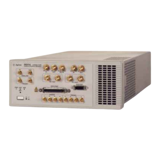
Introducing the N8241/2A AWGs The N8241A and N8242A are wideband arbitrary waveform generators (AWGs) capable of creating high-resolution waveforms for radar, satellite and frequency agile communication systems. Each channel of the AWGs operates at 1.25 GSa/s. The N8241A features 15 bits of vertical resolution and the N8242A 10 bits. Both AWGs offer dual differential output channels to drive both single-ended and balanced designs. -
Page 14: Front Panel Interface
Introducing the N8241/2A AWGs Front Panel Interface Front Panel Interface Figure 1-1 N8241/2A Front Panel Status Indicators Item Description Name EXT CLK IN Use this 50 ohm SMA connector to input an external sample clock. It will accept clock rates in the range of 100 MS/s through 1.25 GS/s. - Page 15 Introducing the N8241/2A AWGs Front Panel Interface Item Description Name CH 1/CH2 Out The CH 1 OUT and CH 2 OUT positive (+) connectors are used for single-ended operation. Use both the positive (+) and negative (-) connectors for differential operation. Refer “Signal Conditioning”...
- Page 16 Introducing the N8241/2A AWGs Front Panel Interface Item Description Name Reset The “RST” button enables you to put the LAN configuration of the instrument into a known state. When you press this button the following settings are made and the system reboots: •...
-
Page 17: Status Indicators
Introducing the N8241/2A AWGs Front Panel Interface Status Indicators The power indicator has the following states: State Power Status Illumination No Power None STANDBY Standby Power Solid Amber Power is on Solid Green The LAN indicator has the following states:... - Page 18 Introducing the N8241/2A AWGs Front Panel Interface 1588 The IEEE 1588 Clock Status has the following states: State Clock Status Illumination Not synchronized None Synchronized, clock is IEEE 1588 Solid Green Slave Synchronized, clock is IEEE 1588 Blinking Green Master...
-
Page 19: Rear Panel Interface
Introducing the N8241/2A AWGs Rear Panel Interface Rear Panel Interface Figure 1-2 N8241A Rear Panel Item Description Name LXI TRIG BUS This interface enables the instrument to detect any LXI trigger bus events or LXI LAN-based events and can output such events. - Page 20 Introducing the N8241/2A AWGs Rear Panel Interface Item Description Name This local area network (LAN) interface allows communication through a 100BaseT LAN cable. The USB port is reserved for future applications. Electrostatic discharge (ESD) can damage the highly sensitive components in your instrument.
-
Page 21: Graphical User Interface (Gui)
Introducing the N8241/2A AWGs Graphical User Interface (GUI) Graphical User Interface (GUI) The tab-based graphical interaction of the GUI gives instant access to the AWG parameters, making it easy to configure signal output. Each tab is labeled with its contents, enabling quick access to all functions. -
Page 22: Getting Started
Introducing the N8241/2A AWGs Getting Started Getting Started System Requirements Hardware • Personal computer (PC) with LAN capability • Agilent E4440A Spectrum Analyzer or equivalent (system verification) Supported Operating Systems ® • Windows 2000, Service Pack 4.0 or later ®... - Page 23 Introducing the N8241/2A AWGs Getting Started CAUTION Before switching on this instrument, make sure the supply voltage is in the specified range. 6. Toggle the front panel switch to turn on the AWG module. Chapter 1...
-
Page 24: Connecting To The Awg Over The Lan
VISA driver. If it is operating as the secondary driver, and another VISA such as NI VISA is the primary, you will need to add the N8241/2A using the tools of the primary VISA. The Agilent IO Libraries will alert you to this condition. - Page 25 Introducing the N8241/2A AWGs Getting Started 4. Enter the host name of the AWG in the LAN Instrument secondary window. 5. Click OK. Chapter 1...
- Page 26 Introducing the N8241/2A AWGs Getting Started 6. The AWG is now configured to the PC. Chapter 1...
-
Page 27: Verifying System Operation
Introducing the N8241/2A AWGs Verifying System Operation Verifying System Operation Prior to verifying system operation, the N8241A software must be installed on the PC and the LAN line connected to the PC and AWG module. For more information refer to “Installing the Software”... - Page 28 Introducing the N8241/2A AWGs Verifying System Operation Output drops to 0.250 volts. Select the Clock tab and confirm that the (AutoSense) 10MHz REF IN is of the user interface, configured correctly. In the Quick Play section browse and select the 400MHzTone.bin waveform file found on the CD for channel 1 and 2 6.
- Page 29 Introducing the N8241/2A AWGs Verifying System Operation Figure 1-4 N8241A Playback of a 400 MHz Tone Figure 1-5 N8242A Playback of a 400 MHz Tone You should get the same performance when you connect channel 2 positive (+) to the spectrum analyzer RF input connector.
-
Page 30: Shutting Down The System
Introducing the N8241/2A AWGs Shutting Down the System Shutting Down the System Close the N8241A Control Utility. Toggle the front panel switch to place the AWG module in standby mode. Chapter 1... -
Page 31: Maintenance
Introducing the N8241/2A AWGs Maintenance Maintenance Cleaning the Instrument To prevent electrical shock, disconnect the instrument and/or system from mains before cleaning. Use a dry cloth or one slightly dampened with water to clean the external case parts. Do not attempt to clean internally. - Page 32 Introducing the N8241/2A AWGs Maintenance Chapter 1...
-
Page 33: Basic Operation
Generating a Single Tone Signal Generating a Multi-tone Signal Creating and Playing a Sequence Synchronizing Two N8241/2A Modules Using Programmatic Interfaces IVI-C Driver Functionality MATLAB Interface MATLAB Example 1, Creating and Playing a Waveform MATLAB Example 2, Synchronizing Two N8241/2A AWGs C/C++ Example Program... -
Page 34: Using The Graphical User Interface
Basic Operation Using the Graphical User Interface Using the Graphical User Interface Generating a Single Tone Signal Use the following procedure as a guide to basic single-ended waveform playback with the N8241A or N8242A AWG. All waveform parameters need to be set prior to waveform playback NOTE A spectrum analyzer is required to display the waveforms... - Page 35 Basic Operation Using the Graphical User Interface 4. To select the DDS option 330 (lower-left corner of the display), refer to “Selecting the DDS Option” on page 99 5. Select the Output tab and connect a single-ended signal conditioning path to CH1 OUT (+) (click on the node that you want to connect) The connection will automatically enable differential mode.
- Page 36 Basic Operation Using the Graphical User Interface configured correctly. 7. In the Quick Play section of the user interface, browse and select the desired single-tone waveform file for Channel 1 Waveform. The AWG accepts data formatted as 16-bit signed integers ignoring the LSB. NOTE Different waveforms can be loaded into channel 1 and 2, but the length of the waveforms must be the same.
- Page 37 Basic Operation Using the Graphical User Interface N8241A and greater than –50.0 dBc for the N8242A. Figure 2-1 N8241A Playback of a 100 MHz Tone Figure 2-2 N8242A Playback of a 100 MHz Tone Chapter 2...
-
Page 38: Generating A Multi-Tone Signal
Basic Operation Using the Graphical User Interface Generating a Multi-tone Signal Connect the channel 1 positive (+) output to the spectrum analyzer RF input connector. Open the user interface by double-clicking the N8241A icon placed on the desktop during installation. Select the Output tab and connect a single-ended signal conditioning path to CH1 OUT (+) (click on the node that you want to connect). - Page 39 Basic Operation Using the Graphical User Interface In the Quick Play section of the user interface, browse and select the desired multi-tone waveform file for Channel 1 Waveform. The AWG accepts data formatted as 16-bit signed integers ignoring the LSB. NOTE Different waveforms can be loaded into channel 1 and 2, but the length of the waveforms must be the same.
- Page 40 Basic Operation Using the Graphical User Interface Figure 2-3 N8241A Playback of Five Tones Figure 2-4 N8241A Playback of Five Tones Chapter 2...
-
Page 41: Creating And Playing A Sequence
Basic Operation Using the Graphical User Interface Creating and Playing a Sequence Connect the channel 1 positive (+) output to the spectrum analyzer RF input connector. Open the user interface by double-clicking the N8241A icon placed on the desktop during installation. Select the Output tab and connect a single-ended signal conditioning path to CH1 OUT (+) (click on the node that you want to connect). - Page 42 Basic Operation Using the Graphical User Interface 5. Select the Sequencer tab. 6. From the Segment List select Add. This will bring up a Segment Information secondary window. Browse and select the 500 MHz waveform, then click OK. NOTE For dual channel sequencing, add the same waveform to both channel 1 and channel 2.
- Page 43 Basic Operation Using the Graphical User Interface Enter Repetition Count secondary window. Enter 5000 repetitions and click OK. 12. Repeat steps 9, 10, and 11 for the 100 MHz and two-tone waveforms. 13. In the Sequence Definition area, select segment ID 2 and move it below ID 3 using the down arrow.
- Page 44 Basic Operation Using the Graphical User Interface Figure 2-6 N8241A Playback of a Sequence Chapter 2...
-
Page 45: Synchronizing Two N8241/2A Modules
Basic Operation Using the Graphical User Interface Synchronizing Two N8241/2A Modules Internal Clock Synchronization Using Continuous Mode When synchronizing two modules using the internal clock, one unit is designated as the Master and the other unit is designated as the Slave. The Master unit sources the sample clock and the sync clock signals. - Page 46 Basic Operation Using the Graphical User Interface Figure 2-7 Cabling for Two AWG Synchronization Turn the system on. Chapter 2...
-
Page 47: Selecting The Master Unit
Basic Operation Using the Graphical User Interface Selecting the Master Uni 1. Open an N8241A Control Utility session (double-click the Agilent N8241A icon on the desktop). 2. In the N8241A Open dialog, enter the VISA address for the master unit, then click OK. -
Page 48: Initiating Synchronous Playback
Basic Operation Using the Graphical User Interface Markers Tab • Marker 4 is assigned to a Software marker and is grayed out Triggers Tab • Start trigger is assigned to Trigger 4 and is grayed out Selecting the Slave Unit 1. -
Page 49: Using Programmatic Interfaces
Basic Operation Using Programmatic Interfaces Using Programmatic Interfaces IVI-C Driver Functionality The IVI Foundation’s class driver specification for function generators has been the model for the features in the N8241A and N8242A AWGs. This includes the recommended method to incorporate attributes for instrument-specific functions. Please refer to IVI-3.15 IviLxiSync Specification, IVI-4.3 IviFgen Class Specification, and IVI-3.1 Driver Architecture Specification for more information. -
Page 50: Matlab Example 1, Creating And Playing A Waveform
= [ch1; ch2]; % Open a session disp('Opening a session to the instrument'); [instrumentHandle, errorN, errorMsg] = agt_awg_open('TCPIP','TCPIP0::A-N8241-90XXX::inst0::INST R'); if(errorN ~= 0) % An error occurred while trying to open the session. disp('Could not open a session to the instrument');... - Page 51 Basic Operation Using Programmatic Interfaces disp('Enabling the instrument output'); [errorN, errorMsg] = agt_awg_setstate(instrumentHandle, 'outputenabled', 'true'); if(errorN ~= 0) % An error occurred while trying to enable the output. disp('Could not enable the instrument output'); return; disp('Setting the instrument to ARB mode'); [errorN, errorMsg] = agt_awg_setstate(instrumentHandle, 'outputmode', 'arb');...
-
Page 52: Matlab Example 2, Synchronizing Two N8241/2A Awgs
MATLAB Example 2, Synchronizing Two N8241/2A AWGs MATLAB Example 2, Synchronizing Two AWG Modules % N6030 Matlab Interface, Version 1.12 % Copyright (C) 2005, 2006 Agilent Technologies, Inc. % This example initiates dual module synchronized waveform % playback. - Page 53 Basic Operation Using Programmatic Interfaces % Try to open a session disp('Opening a session to the instrument'); [instrumentHandle2, errorN, errorMsg] = agt_awg_open('TCPIP','TCPIP0::A-N8241-90XXX::inst0::INST R'); if errorN ~= 0 disp(errorN); disp(errorMsg); disp('program stopped'); return; else disp('ok'); [instrumentHandle1, errorN, errorMsg] = agt_awg_open ('TCPIP','TCPIP0::A-N8241-90XXX::inst0::INSTR');...
- Page 54 Basic Operation Using Programmatic Interfaces disp(errorMsg); disp('program stopped'); return; else disp('ok'); [errorN, errorMsg] = agt_awg_setstate(instrumentHandle2, 'outputenabled', 'true'); if errorN ~= 0 disp(errorN); disp(errorMsg); disp('program stopped'); return; else disp('ok'); disp('Setting the instrument to ARB mode'); [errorN, errorMsg] = agt_awg_setstate(instrumentHandle1, 'outputmode', 'arb'); if errorN ~= 0 disp(errorN);...
- Page 55 Basic Operation Using Programmatic Interfaces [errorN, errorMsg] = agt_awg_setstate(instrumentHandle2, 'outputmode', 'arb'); if errorN ~= 0 disp(errorN); disp(errorMsg); disp('program stopped'); return else disp('ok'); disp('Setup the Master'); [errorN, errorMsg] = agt_awg_setstate(instrumentHandle1, 'syncmode', 'master'); if errorN ~= 0 disp(errorN); disp(errorMsg); disp('program stopped'); return else disp('ok');...
- Page 56 Basic Operation Using Programmatic Interfaces disp(errorMsg); disp('proram stopped'); return else disp('ok'); disp('Transfering the waveform to the instrument'); [waveformHandle, errorN, errorMsg] = agt_awg_storewaveform(instrumentHandle1, waveform); if errorN ~= 0 disp(errorN); disp(errorMsg); disp('program stopped'); return else disp('ok'); [waveformHandle, errorN, errorMsg] = agt_awg_storewaveform(instrumentHandle2, waveform); if errorN ~= 0 disp(errorN);...
- Page 57 Basic Operation Using Programmatic Interfaces instrument'); [errorN, errorMsg] = agt_awg_playwaveform(instrumentHandle2, waveformHandle); if errorN ~= 0 disp(errorN); disp(errorMsg); disp('program stopped'); return else disp('ok'); [errorN, errorMsg] = agt_awg_playwaveform(instrumentHandle1, waveformHandle); if errorN ~= 0 disp(errorN); disp(errorMsg); disp('program stopped'); return else disp('ok'); disp('Init Generation'); [errorN, errorMsg] = agt_awg_initiategeneration(instrumentHandle2);...
- Page 58 Basic Operation Using Programmatic Interfaces else disp('ok'); [errorN, errorMsg] = agt_awg_initiategeneration(instrumentHandle1); if errorN ~= 0 disp(errorN); disp(errorMsg); disp('program stopped'); return else disp('ok'); disp('Press ENTER to close the instrument session and conclude this example.'); Chapter 2...
-
Page 59: C/C++ Example Program
// Visual Studio you might use this #define WFM_LENGTH 800 //should be integer divisible by int main(int argc, char* argv[]) ViStatus rc; ViRsrc resourceName = "TCPIP0::A-N8241-90XXX::inst0::INSTR"; // Set // this to match your hardware ViBoolean IDQuery = VI_FALSE; Chapter 2... - Page 60 Basic Operation Using Programmatic Interfaces ViBoolean resetDevice = VI_TRUE; ViSession session = 0; ViInt32 wfmHandle1; ViInt32 wfmHandle2; int i; double twopi; double ifWfm[WFM_LENGTH]; double Fsig = 500e6; // Set this to a CW frequency // <= 500 MHz double Fs = 1.25e9; // Sample Clock Frequency // Initialize N8241A and setup session handle rc = AGN6030A_init(resourceName, IDQuery, resetDevice, &session);...
- Page 61 Basic Operation Using Programmatic Interfaces if (rc != VI_SUCCESS) return -1; rc = AGN6030A_ConfigureOutputEnabled(session, "2", VI_TRUE); if (rc != VI_SUCCESS) return -1; // Select the Internal Sample Clock and an //External Reference Clock rc = AGN6030A_ConfigureSampleClock(session, AGN6030A_VAL_CLOCK_INTERNAL, Fs); if (rc != VI_SUCCESS) return -1;...
- Page 62 Basic Operation Using Programmatic Interfaces ifWfm[i] = sin(twopi * (Fsig/Fs) * (double)i); // Set N8241A output mode to ARB in preparation of // downloading and playing our waveform. rc = AGN6030A_ConfigureOutputMode(session, AGN6030A_VAL_OUTPUT_ARB); if (rc != VI_SUCCESS) return -1; // Download the waveform to both channels 1 and 2 // even if 2is not used.
- Page 63 Basic Operation Using Programmatic Interfaces Chapter 2...
- Page 64 Basic Operation Using Programmatic Interfaces Chapter 2...
-
Page 65: Theory Of Operation
Theory of Operation This chapter includes the following topics that explain the theory behind the functionality of the N8241A and N8242A Arbitrary Waveform Generators. N8241/2A Block Diagram Clock I/O Waveform Playback Basic Sequencing Advanced Sequencing Markers Triggers Synchronous Triggers Signal Conditioning... -
Page 66: N8241/2A Block Diagram
Theory of Operation N8241/2A Block Diagram N8241/2A Block Diagram N is the Sync clock prescaler divide ratio. Refer to “Synchronous Triggers”. The N8241A and N8242A Arbitrary Waveform Generators (AWGs) are dual channel AWGs that offer wide bandwidth as well as excellent signal fidelity. The AWG was developed incorporating a high performance Agilent digital-to-analog converter (DAC) designed to clock up to 1.25 GHz. -
Page 67: Clock I/O
Theory of Operation Clock I/O Clock I/O 10 MHz In A 10 MHz reference is required when using the internal clock. You can use either the (AutoSense) 10 MHz REF IN (the default) or the AUX 10 MHz REF IN connector to supply the 10 MHz reference. -
Page 68: Waveform Playback
Theory of Operation Waveform Playback Waveform Playback Waveforms Single waveforms are played back in one of two modes: • Continuous The waveform repeats indefinitely. • Burst Once a trigger is received, the waveform repeats a specified number of times. Waveform Sequencer Function Sequencing provides a method of waveform memory compression using a play table, sequencer memory, and waveform memory. -
Page 69: Basic Sequencing
Theory of Operation Waveform Playback Basic Sequencing A sequence is a sequential list of segments and may occur anywhere in the sequence memory. A sequence may have a preamble of one or more segments that is played once at the start of the sequence, but not repeated until the sequence is started again. Waveforms are stored in dedicated banks of memory for channel 1 and channel 2. -
Page 70: Advanced Sequencing
Theory of Operation Waveform Playback segments. Each waveform segment is played out according to its segment and sequence definition. A total of 1 million (220) loops can be defined for each segment. After the last segment loop is executed, the entire sequence can repeat continuously or for the predefined number of times. -
Page 71: Scenario Advance Mode
Theory of Operation Waveform Playback Scenario Advance Mode The play table can be configured to play a scenario once or continuously after starting. Single • The scenario plays once and then waits for a trigger. While waiting for a trigger, the value of the last waveform continues to play. - Page 72 Theory of Operation Waveform Playback Figure 3-2 Advanced Sequencer Flow Chart Figure 3-3 Chapter 3...
-
Page 73: Waveform Advancement
Theory of Operation Waveform Playback Waveform Advancement In basic sequencing, waveforms always advance to the next waveform automatically after the specified number of repetitions. With advanced sequencing, waveforms can be configured to advance in one of four ways: • Automatic The waveform automatically advances to the next waveform after completing the specified number of loop repetitions. -
Page 74: Scenario Start/Jump Trigger Source
Theory of Operation Waveform Playback • End of Scenario The current scenario is completed before jumping to the new scenario. The jump latency is the longer of either the jump immediate latency or the length of the remaining part of the current waveform. If the remaining part of the scenario is less than the jump immediate latency, the scenario is repeated one more time before jumping. - Page 75 Theory of Operation Waveform Playback Figure 3-3 Waveform Play Flow Chart Chapter 3...
- Page 76 Theory of Operation Waveform Playback Figure 3-4 Scenario and Sequence Play Flow Charts Chapter 3...
-
Page 77: Markers
Theory of Operation Waveform Playback Markers The N8241/2A AWG provides four front panel marker output connectors that can be used for system synchronization and triggering. The following markers can be enabled: • Ch 1 Memory Marker 1 and Memory Marker 2 •... -
Page 78: Triggers
Theory of Operation Waveform Playback front panel trigger out connector. There are 16 marker output selections for the LXI trigger bus; LAN 0–7 and LXI 0–7. Markers can be set in the sequencer to be at any point in the data with a positive or negative polarity. -
Page 79: Triggers 1,2,3,4
Theory of Operation Waveform Playback Triggers 1,2,3,4 These four trigger inputs can be used to control waveforms in the sequencer. Hardware trigger inputs may be configured to generate events on the rising or falling SYNC clock edges, but not both at the same time. The trigger threshold can be set between –4.5 and +4.5V. -
Page 80: Synchronous Triggers
Theory of Operation Waveform Playback Synchronous Triggers Triggers are registered into the AWG using the SYNC clock. The SYNC clock is nominally at the sample clock frequency divided by 8. However, at lower sample rates an internal variable modulus prescaler selects other binary divide ratios: 4, 2, and 1. - Page 81 Theory of Operation Signal Conditioning Signal Conditioning Single-Ended Mode Single-ended mode has two modes of operation with signal output through the positive (+) port. The negative port (-) is reserved for differential mode. Passive mode has an adjustable output level of up to 0.5Vp-p This mode gives the greatest single-ended signal fidelity because there is a balun in the path that suppresses the second order harmonic.
-
Page 82: Signal Conditioning
Theory of Operation Signal Conditioning Differential Mode The differential mode has an output level of up to 0.5Vp-p. This mode provides exceptional signal fidelity into true differential inputs (which provide common mode rejection). A larger differential output voltage is also obtained without the use of the amplifier. -
Page 83: Digital Predistortion
Theory of Operation Digital Predistortion Digital Predistortion The predistortion function compensates for the variation in the magnitude of the output response as a function of frequency. This variation is the result of the sin x/x (sinc) roll-off of the internal DAC and the frequency response of the reconstruction filter. - Page 84 Theory of Operation Multiple Module Synchronization Multiple Module Synchronization Within each AWG, the two channels are synchronized by design. Some systems, such as phased array radar, require more than two synchronized channels. The AWG is designed to support the synchronization of up to 16 channels through the use of eight AWGs.
-
Page 85: Multiple Module Synchronization
Theory of Operation Multiple Module Synchronization Figure 3-8 Cabling for Internal Clock Synchronization The trigger cables should all be the same length. The trigger inputs are high impedance and several inputs can be driven in parallel without matched passive splitters. The synchronous trigger timing can be determined in the same way as any synchronous trigger into the AWG. -
Page 86: Synchronization Using An External Clock
Theory of Operation Multiple Module Synchronization external Sample clock can be in the range of 625 MHz to 1.25 GHz. The Sample clock provides the final retiming of the analog output from each AWG. Any skew in the Sample clock cable delays between the multiple modules will result in the same skew in the analog outputs. - Page 87 Theory of Operation Multiple Module Synchronization Figure 3-9 Cabling Using and External Clock Chapter 3...
- Page 88 Theory of Operation Multiple Module Synchronization Multiple Module Synchronous Trigger Timing Triggers are registered into the AWG using the SYNC clock. The SYNC clock is nominally at the sample clock frequency divided by 8. However at lower sample rates an internal variable modulus prescaler selects other binary divide ratios: 8, 4, 2, and 1.
-
Page 89: Multiple Module Synchronous Trigger Timing
Theory of Operation Multiple Module Synchronization Figure 3-10 Multiple Module Synchronous Trigger Timing Diagram Cable Length and Skew The cabling requirements are as follows: Sample Clock Skew less than 10 mm between modules. The absolute SYNC cable length is Equation given by the as a function of the Sample clock frequency: Sample Clock Skew Formula... - Page 90 Theory of Operation Multiple Module Synchronization Chapter 3...
-
Page 91: Dynamic Sequencing Option
Dynamic Sequencing Option 300 The dynamic sequencing option enables you to access up to eight thousand previously stored scenarios through a 16-bit interface. This functionality gives you the ability to build custom signal scenarios to simulate dynamically changing environments. Dynamic Sequencing AUX PORT Connector Signal Levels Signal Descriptions... -
Page 92: Dynamic Sequencing
Dynamic Sequencing Option 300 Dynamic Sequencing Dynamic Sequencing Dynamic sequencing is a mode where the AWG scenario handle memory is bypassed and scenarios are selectedfrom an external source. You must first load the data into the N8241A LXI-AWG memory, then, in real-time, provide the scenario handles through the AUX PORT input connector. - Page 93 Dynamic Sequencing Option 300 Dynamic Sequencing Figure 4-2 AUX PORT Pin Outs Table 4-1 Pin Assignment Pin No. Signal Assignment Trigger Ground Data Valid CH 1/CH 2 (Reserved, set low) Ground Ground Ground Chapter 4...
-
Page 94: Signal Levels
Dynamic Sequencing Option 300 Dynamic Sequencing Signal Levels All pins are configured as 2.5 V, LVCMOS inputs. The logic levels must be within the following ranges: −0.2 to +0.5 V High +2.0 to +2.8 V Signal Descriptions Data Input The input data represents a handle to the next scenario to be played by the AWG module. -
Page 95: Direct Digital Synthesis Option
Direct Digital Synthesis Option 330 The direct digital synthesis (DDS) architecture in the N8241A Series AWGs enables you to create basic waveforms in the AWG memory and then modify the behavior of the waveforms with profiles for amplitude, phase and frequency modulations. -
Page 96: Direct Digital Synthesis
Direct Digital Synthesis Option 330 Direct Digital Synthesis Direct Digital Synthesis The N8241A direct digital synthesis application can be managed through the Control Utility graphical user interface (GUI) or one of the supported programmatic interfaces. Accessing DDS through the GUI is the easiest way to view the functionality as many details are handled by the software in the background. -
Page 97: Direct Digital Synthesis Using The Control Utility
Direct Digital Synthesis Option 330 Direct Digital Synthesis Direct Digital Synthesis Using the Control Utility NOTE A spectrum analyzer is required to display the waveform. Configuring the Equipment 1. Connect a 10 MHz reference from the spectrum analyzer to the AWG front panel connector. -
Page 98: Configuring The Clock
Direct Digital Synthesis Option 330 Direct Digital Synthesis path to CH1 OUT (+) (click on the node that you want to connect). The connection will automatically enable differential mode. Click on the negative (-) node to open this path and enable single-ended mode. Configuring the Clock 1. -
Page 99: Configuring The Sequencer
Direct Digital Synthesis Option 330 Direct Digital Synthesis 2. Use the default setting for the Interpolation Ratio. Configuring the Sequencer 1. Select the DDS Sequencer tab. 2. From the Segment List select Add. This brings up a Segment Information window. 3. - Page 100 Direct Digital Synthesis Option 330 Direct Digital Synthesis 4. In the Segment List, select the DDS_All_Ones waveform. Chapter 5...
- Page 101 Direct Digital Synthesis Option 330 Direct Digital Synthesis 5. In the Sequence Definition area, select Add. This brings up the DDS Sequence Input window. 6. Enter 5000 repetitions and accept all default settings. Click OK. NOTE The values entered in the DDS Sequence Input window are recorded in the sequence definition area of the Sequencer tab.
- Page 102 Direct Digital Synthesis Option 330 Direct Digital Synthesis Figure 5-2 Sequencer Tab 9. Click Download & Play. The spectrum of the sequence should be similar to the one shown in Figure 5-3. Chapter 5...
-
Page 103: Out Of Range Input Values
Direct Digital Synthesis Option 330 Direct Digital Synthesis Figure 5-3 Playback of a Sequence The 250 MHz carrier (marker 1) and the 400 MHz carrier (marker 2) are combined with a waveform composed of all ones.This illustrates how the DDS engine produces sine waves when a constant frequency is specified. Out of Range Input Values Some values may cause an 'out of range' condition. - Page 104 Direct Digital Synthesis Option 330 Direct Digital Synthesis Figure 5-4 DDS Sequence Input Window Notice the question marks in the Frequency Slope box. This is occurs when the combination of the loop count, the initial frequency, and the end frequency cannot be calculated correctly. If you select OK, a message window comes up.
- Page 105 Direct Digital Synthesis Option 330 Direct Digital Synthesis Figure 5-6 Calculated Valid Settings The end frequency value was adjusted to enable the slope count. NOTE This type of ‘out of range’ condition may also occur with amplitude settings. Chapter 5...
-
Page 106: Theory Of Operation
Direct Digital Synthesis Option 330 Theory of Operation Theory of Operation The Direct Digital Synthesis, Option 330, is a powerful tool for those customers who are using the N8241A Arbitrary Waveform Generator (AWG) to synthesize waveforms best expressed in the frequency domain. Traditionally, waveforms are expressed in the time domain, sampled, and then stored in waveform memory for eventual playback. - Page 107 Direct Digital Synthesis Option 330 Theory of Operation requiring phase continuous frequency hopping. The DDS generates both sine and cosine outputs for use in the complex modulator. Refer to Figure 5-7. To allow waveform memory to be played back at a rate slower than the AWG sample rate, interpolation filters have been added to the main FPGA, for both channels.
- Page 108 Direct Digital Synthesis Option 330 Theory of Operation Figure 5-7 Chapter 5...
-
Page 109: Troubleshooting
Troubleshooting The following topics are included in this chapter. Software Removing the Software Moving the Software Updating the Software Initializing the LAN Configuration Contacting Agilent... -
Page 110: Software
Troubleshooting Software Software Removing the Software If it is necessary to remove the N8241A software, go to: Start > Settings > Control Panel > Add/Remove Programs 1. Select Agilent N8241A AWG (Version), then select Remove. You may need to restart the PC, but this will completely remove all of the files. Moving the Software If it becomes necessary to move the N8241A software, complete the instructions Removing the Software... -
Page 111: Initializing The Lan Configuration
Troubleshooting Initializing the LAN Configuration Initializing the LAN Configuration On the front of the instrument, near the power switch, is a recessed button labeled “RST”. This button enables you to put the LAN configuration of the instrument into a known state. This is useful if the LAN address gets set to an unknown value. When you press this button (a straightened paper clip will do the job) the following settings are made and the system reboots: •... -
Page 112: Contacting Agilent
Troubleshooting Contacting Agilent If it becomes necessary to return the N8241/2A AWG to the factory, use the original or comparable packaging. Chapter 6... -
Page 113: Technical Characteristics
Technical Characteristics The following topics are included in this chapter. Technical Characteristics General Characteristics... - Page 114 Technical Characteristics Technical Characteristics Channels Two independent channels available as baseband or IF outputs CH1: Single-ended and differential CH2: Single-ended and differential Modulation bandwidth 500 MHz per channel (1 GHz IQ bandwidth) Resolution N8241A: 15 bits N8242A: 10 bits Output spectral purity (CH1 and CH2) Harmonic Distortion: 1 kHz to 500 MHz •...
- Page 115 Technical Characteristics Noise floor • N8241A < -150 dBc/Hz across the channel bandwidth • N8242A < -150 dBc/Hz across the channel bandwidth Sample clock • Internal: Fixed 1.25 GS/s • Internal clock output: +3 dBm nominal into 50 ohm load •...
- Page 116 Technical Characteristics Waveform length • 8 MS per channel (16 MS with option 016) • Minimum waveform length: 128 samples • Waveform granularity: 8 samples Segments From 1 to 32,768 unique segments can be defined consisting of waveform start and stop address, repetitions and marker enable flags. Sequences Up to 16,384 total unique waveform segments can be combined with separate loop counts to form a sequence.
- Page 117 Technical Characteristics Trigger In* • Trigger impedance: 4k ohms • Trigger level:LVTTL *Trigger In has additional latency. LXI Trigger Bus • All physical and electrical characteristics conform to LXI Standard Revision 1.1. External markers Markers can be defined for each waveform segment. Front Panel Markers 1/2/3/4 •...
- Page 118 Technical Characteristics • 2.4V nominal when terminated into a 50 ohm load *Trigger Out has additional latency. LXI Trigger Bus • All physical and electrical characteristics conform to LXI Standard Revision 1.1 Module synchronization • Hardware supports synchronization of multiple AWGs with future software enhancements.
- Page 119 Technical Characteristics • Single-Ended Active Mode1.0Vp-p with ±0.2Vp-p • Differential Active Mode: N/A Reconstruction filters • 500 MHz and 250 MHz realized as 7-pole elliptical filters plus thru-line output Chapter 7...
- Page 120 Technical Characteristics General Characteristics Power Line power: 100/120/220/240 V AC, 50/60 Hz, 100 Watts maximum Environmental Samples of this product have been type tested in accordance with the Agilent Environmental Test Manual and verified to be robust against the environmental stresses of Storage, Transportation, and End-use; those stresses include but are not limited to temperature, humidity, shock vibration, altitude, and power line conditions.
- Page 121 • Electrostatic Discharge Immunity - IEC 61000-4-2: passes criterion C Testing according to IEC 61000-4-2: showed that the exposure of the data port to electrostatic discharge may interrupt operation of the N8241/2A. Operation can be restored by reloading the desired waveforms and restarting.
- Page 122 Technical Characteristics Options • N8241A-016: Waveform memory expansion to 16 MS per channel • N8241A-300 Dynamic Sequencing • N8241A-330 Direct Digital Synthesis (DDS) Chapter 7...
- Page 123 IVI-C n8241/2a MATLAB scenario pointer source programming examples trigger general safety information C/C++ generating a signal MATLAB, creating and playing a multi-tone waveform...
- Page 124 unit...
Need help?
Do you have a question about the N8241 and is the answer not in the manual?
Questions and answers