Table of Contents
Advertisement
Advertisement
Table of Contents

Related Manuals for Keysight Technologies M9703A


Summary of Contents for Keysight Technologies M9703A
- Page 1 Startup Guide Keysight Multi-Channel Antenna Calibration Reference Solution Notice: This document contains references to Agilent. Please note that Agilent's Test and Measurement business has become Keysight Technologies. For more information, go to www.keysight.com.
- Page 3 Copyright Notice HEREIN. SHOULD KEYSIGHT AND THE release, perform, display, or disclose © Keysight Technologies 2013 - 2015 USER HAVE A SEPARATE WRITTEN commercial computer software or No part of this manual may be AGREEMENT WITH WARRANTY TERMS...
- Page 4 possible injury. Read and follow all temperature range is not maintained, intended to be used with impedance- installation, operation, and module surface temperatures may limited sources. NEVER connect maintenance information carefully exceed safe handling conditions which switching cards directly to AC mains. before using the product.
- Page 5 Annex 1, this product is classified as “Monitoring and Control To prevent electrical shock, disconnect instrumentation” product. Do not the Keysight Technologies instrument dispose in domestic household waste. The CE mark is a registered trademark from mains before cleaning. Use a dry To return unwanted products, contact of the European Community.
-
Page 7: Table Of Contents
Typical System Performance The MAC Reference Solution System Software System Hardware Product specifications & characteristics M9703A AXIe 12-bit digitizer/wide-band receiver M9362A-D01 PXIe microwave quad downconverter M9352A PXI hybrid amplifier/attenuator N5183B MXG microwave analog signal generator N5193A UXG microwave agile signal generator... - Page 8 viii...
-
Page 9: Multi-Channel Antenna Calibration (Mac) Introduction
Multi-Channel Antenna Calibration (MAC) Introduction Multi-Channel Antenna Calibration (MAC) Introduction Smart antenna architectures incorporating multiple antenna elements in an array are used in many applications. Wireless communications standards like 802.11ac, radio astronomy and array RADARs are all examples of applications where multiple antennas are employed for various requirements derived from spatial signal processing. -
Page 10: The Mac Reference Solution
Multi-Channel Antenna Calibration (MAC) Introduction The MAC Reference Solution The MAC Reference Solution The following shows a typical MAC Reference Solution block diagram. . System Software The MAC Demo Software has been been designed to assist in the development of the overall test system software. -
Page 11: System Hardware
The following documents will assist you in designing and configuring your MAC Reference Solution system: Solutions brochure http://literature.cdn.keysight.com/litweb/pdf/5991-4537EN.pdf Configuration guide. http://literature.cdn.keysight.com/litweb/pdf/5991-4583EN.pdf M9703A AXIe High-Speed Digitizerr M9536A AXIe Embedded Controller M9502A and M9505A AXIe Chassis M9018A PXIe Chassis Keysight Y1299A-003 MAC Reference Solution Startup Guide... - Page 12 Multi-Channel Antenna Calibration (MAC) Introduction The MAC Reference Solution N5183B MXG Analog Signal Generator E8257D PSG Analog Signal Generator M9037A PXIe Embedded Controller M9352A PXI Amplifier/Attenuator M9362A-D01 PXIe Microwave Quad Downconverter N5193A UXG Agile Signal Generator Keysight Y1299A-003 MAC Reference Solution Startup Guide...
-
Page 13: Product Specifications & Characteristics
When scaling up, a system of 40 synchronous channels acquiring at 1.6 GS/s in only 4U of rack-mount space can be easily built by combining the M9703A with the M9505A 5-slot AXIe Chassis and U1092A AcqirisMAQS software. -
Page 14: M9352A Pxi Hybrid Amplifier/Attenuator
Multi-Channel Antenna Calibration (MAC) Introduction Product specifications & characteristics M9352A PXI hybrid amplifier/attenuator 4 channels 1 GHz analog bandwidth http://literature.cdn.keysight.com/litweb/pdf/5990-9964EN.pdf The Keysight M9352A PXI-H IF Amplifier/Attenuator, 10 MHz to 1 GHz is a one-slot, 4-channel, PXI Hybrid IF Amplifier/Attenuator with 1 GHz analog bandwidth providing IF signal conditioning for use in multi-channel modular solutions. -
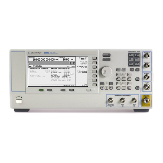
Page 15: E8257D Psg Analog Signal Generator
25 °C, which may be useful in the application of the product. Unless otherwise noted, this data sheet applies to units with serial numbers ending with 50420000 or greater. www.keysight.com/find/e8257d M9703A 12-Bit High-Speed Digitizer http://literature.cdn.keysight.com/litweb/pdf/M9703-90001.pdf Keysight Y1299A-003 MAC Reference Solution Startup Guide... -
Page 16: Unpack And Inspect
Unpack and Inspect Unpack and Inspect The modules are shipped in materials which prevent damage from static. Modules should only be removed from the packaging in an anti-static area ensuring that correct anti-static precautions are taken. Store all modules in anti-static envelopes when not in use. Electrostatic discharge (ESD) can damage or destroy electronic components. -
Page 17: Inspect For Damage
Unpack and Inspect Inspect for Damage Inspect for Damage After unpacking an instrument, inspect it for any shipping damage. Report any damage to the shipping agent immediately, as such damage is not covered by the warranty (see warranty information at beginning of this document). To avoid damage when handling a module, do not touch exposed connector pins. - Page 18 Unpack and Inspect Return an Instrument for Service nuts and place the instrument in a sealed container and mark the container - FRAGILE-. 5. On the shipping label, write ATTENTION REPAIR DEPARTMENT and the RMA number. In your correspondence, refer to the modules by serial number and the instrument by model number.
-
Page 19: Pxie Chassis And Modules
PXIe Chassis and Modules PXIe Chassis PXIe Chassis and Modules PXIe Chassis The following two documents provide information on setting up the M9018A Startup Guide http://literature.cdn.keysight.com/litweb/pdf/M9018-90001.pdf M9018A User's Guide http://literature.cdn.keysight.com/litweb/pdf/M9018-90005.pdf The M9018A Startup Guide is divided into the following sections: STEP 1: Verify the Shipment Contents—This section describes how a chassis system is shipped and what is included with the chassis itself. -
Page 20: Pxie Modules
PXIe Chassis and Modules PXIe Modules How to configure the M9018A chassis to meet your needs. Parameters such as the following can be configured: The PCIe link configuration: 1x8, 2x8, or 4x4 Voltage limits around the power supply rails at which an alarm will be gen- erated if a rail falls outside of its limit The temperature at which an alarm will be generated if the chassis exceeds this temperature... -
Page 21: Axie Chassis And Modules
AXIe Chassis and Modules Introduction AXIe Chassis and Modules Introduction The Keysight M9502A (2-slot) and M9505A (5-slot) AXIe chassis are modular instrument chassis fully compatible with the AXIe 1.0 specification. They allow multiple application-specific instrument modules to share a common chassis frame, power supply, cooling system, PCI Express (PCIe) Gen 2 data bus, Gigabit LAN hub, local bus for module-to-module signaling, and host PC connections. -
Page 22: M9505A 5-Slot Axie Chassis At A Glance
AXIe Chassis and Modules M9505A 5-Slot AXIe Chassis at a Glance M9505A 5-Slot AXIe Chassis at a Glance The M9505A is shipped with bumpers and two carry handles installed for benchtop use (these remove for rack mounting), Slot 1 open and filler panel modules installed in Slots 2 through 5. - Page 23 AXIe Chassis and Modules Chassis and Module Details Step 2: Verify Shipment Contents Step 3: Power-Up and Power-Down Circuit Breaker ON/STANDBY Switch Power Modes To Power Up the Chassis To Power Down the Chassis - Step 4: Set Up the Host PC - Hardware Connections to the Host PC - Step 5: Install IO Libraries and Connect to the Web - Installing the Keysight IO Libraries Suite...
-
Page 24: Mac Demo Software
MAC Demo Software Chassis and Module Details MAC Demo Software The MAC Demo Software has been designed to assist in the development of the overall test system software. The MAC Demo Software is installed on the CD that accompanies the system (Y1299- 10003). -
Page 25: Setup Tab
D – Input Full Scale range selection allows the user to choose a full scale range in Volts for the M9703A(s). This is the range of voltages (centered at Offset) over which the 12-bit ADC quantization steps occur. For M9703A this is either 1V or 2V. - Page 26 O – Slope (trigger) is used to distinguish between rising and falling edges when trigger type is set to edge. P – Option string is the option string literal that is passed to the M9703A IVI-COM driver on initialization. Do NOT change this unless you have consulted the MD1 IVI- COM driver help and clearly understand the syntax because changes can cause seemingly unusual or unpredictable behavior. ...
- Page 27 R – sim is a radio control that allows the user to use simulated M9703A modules. By entering a number of simulated modules in the box to the right of sim and then checking the box at the left, the modules and channels control is cleared and repopulated with virtual (simulated) instances of M9703A modules. ...
- Page 28 MAC Demo Software Setup tab U – Acquire is the third button pressed in the GUI when using actual M9703A hardware. In simulate mode, there is no real hardware to send an initiate command to, so the acquire step is skipped in simulate mode. Acquire will initiate an acquisition across the entire configured M9703A module set and cause the M9703A modules to fill their acquisition RAM. ...
-
Page 29: Preferences Pane
(Initialize button on main form setup tab) C – Clocking Mode specifies which clock mode is used: Ext Clk [=] 3.2GHz sample clock is provided to each M9703A via front-panel SMA clock input (this is currently the only supported option for multi-module sync to achieve best... - Page 30 MAC Demo Software Setup tab E – Trigger Delay allows the user to adjust the position of the trigger inside the acquisition period (per segment). The range of the trigger delay is programmatically set to a symmetric range around t=0 based on the limits imposed by the IVI-COM driver. ...
-
Page 31: Choosing The Default Export Folder
VISA PXI address of the specific M9703A that the cal constants are provided for. If there is more than one M9703A, then the next PXI address is given on the very next line followed again by the list of channels with associated magnitude, phase correction. - Page 32 MAC Demo Software Setup tab Channel3,1,1.99 Channel4,1,2.28 Channel5,1,3.30 Channel6,1,4.48 Channel7,1,3.36 Channel8,1,2.24 B – Module is the specific module that contains the acquisition channel from which we wish to extract magnitude and phase measurements from. It will be identified by the PXI address or a simulated name as shown in the example above.
-
Page 33: Analysis Tab
MAC Demo Software Analysis tab Analysis tab A – Segment is the selected segment for analysis in this tab. All analysis in the plots will concentrate on the segment chosen (in range of 0…n-1 where n = Nbr of Segments from setup tab in main form of GUI). A different value than 0 can be entered here and then subsequently the Recalculate button (G) needs to be pressed to update all plots. - Page 34 0. The example waveform here has ringing on the edges of the phase transitions due to IF filter bandwidth of the DDC in the M9703A, and this windowing technique can improve the precision of the resulting phase measurement assuming some imperfections in centering the rectangular measurement interval using the parameters just discussed.
-
Page 35: Status Tab
Time tags are tracked using a Stopwatch object embedded inside the M9703A object in the application code. The copy to clipboard button is provided to quickly grab the complete history into the PC’s clipboard to paste into a test report. ... - Page 36 This information is subject to change without notice. © Keysight Technologies 2013 - 2015 Edition 1, July, 2015 Printed In USA Y1299-90003 www.keysight.com...
Need help?
Do you have a question about the M9703A and is the answer not in the manual?
Questions and answers