Table of Contents
Advertisement
Quick Links
Advertisement
Table of Contents

Related Manuals for Electro Industries Shark 200


Summary of Contents for Electro Industries Shark 200
- Page 1 V.1.24 March 15, 2018...
- Page 2 This page intentionally left blank.
- Page 3 Electro Industries/GaugeTech. © 2018 Electro Industries/GaugeTech Shark® is a registered trademark of Electro Industries/GaugeTech. The distinctive shapes, styles, and overall appearances of all Shark® meters are trademarks of Electro Industries/GaugeTech. Communicator EXT...
-
Page 4: Electro Industries/Gaugetech Electro Industries/Gaugetech Doc # E149701
This page intentionally left blank. Electro Industries/GaugeTech Electro Industries/GaugeTech E149701 The Leader In Power Monitoring and Smart Grid Solutions The Leader In Power Monitoring and Smart Grid Solutions... - Page 5 516-334-0870 or fax 516-338-4741. Product Warranty Electro Industries/GaugeTech (EIG) warrants all products to be free from defects in material and workmanship for a period of four years from the date of shipment. During the warranty period, we will, at our option, either repair or replace any product that proves to be defective.
- Page 6 Statement of Calibration Our instruments are inspected and tested in accordance with specifications published by Electro Industries/GaugeTech. The accuracy and a calibration of our instruments are traceable to the National Institute of Standards and Technology through equipment that is calibrated at planned intervals by comparison to certified standards.
- Page 7 MISE EN GARDE l'information pour éviter toute blessure ou tout endommagement du produit. About Electro Industries/GaugeTech (EIG) Founded in 1975 by engineer and inventor Dr. Samuel Kagan, Electro Industries/ GaugeTech changed the face of power monitoring forever with its first breakthrough innovation: an affordable, easy-to-use AC power meter.
- Page 8 This page intentionally left blank. Electro Industries/GaugeTech Electro Industries/GaugeTech E149701 The Leader In Power Monitoring and Smart Grid Solutions The Leader In Power Monitoring and Smart Grid Solutions...
-
Page 9: Table Of Contents
Table of Contents Table of Contents Customer Service and Support Product Warranty Statement of Calibration Disclaimer About Electro Industries/GaugeTech 1:Three-Phase Power Measurement 1.1: Three-Phase System Configurations 1.1.1: Wye Connection 1.1.2: Delta Connection 1.1.3: Blondel’s Theorem and Three Phase Measurement 1.2: Power, Energy and Demand 1.3: Reactive Energy and Power Factor... -
Page 10: Table Of Contents
7.9.2: Default Configuration 7-18 7.9.3: Wiring Diagram 7-18 7.10: IEC 61850 Protocol Ethernet Network Card (INP300S) 7-20 Electro Industries/GaugeTech Electro Industries/GaugeTech E149701 TOC-2 The Leader In Power Monitoring and Smart Grid Solutions The Leader In Power Monitoring and Smart Grid Solutions... -
Page 11: Table Of Contents
B-40 C: DNP Mapping C.1: Overview C.2: Physical Layer C.3: Data Link Layer C.4: Application Layer Electro Industries/GaugeTech Electro Industries/GaugeTech E149701 TOC-3 The Leader In Power Monitoring and Smart Grid Solutions The Leader In Power Monitoring and Smart Grid Solutions... -
Page 12: Table Of Contents
E.5: Resetting the IEC 61850 Protocol Ethernet Network Card E-28 E.6: Testing E-29 E-7: Error Codes E-30 Electro Industries/GaugeTech Electro Industries/GaugeTech E149701 TOC-4 The Leader In Power Monitoring and Smart Grid Solutions The Leader In Power Monitoring and Smart Grid Solutions... -
Page 13: Three-Phase Power Measurement
This leads to common voltages of 208/ 120 and 480/277 (where the first number represents the phase-to-phase voltage and the second number represents the phase-to-ground voltage). Electro Industries/GaugeTech E149701 The Leader In Power Monitoring and Smart Grid Solutions... - Page 14 A phasor diagram for the typical connected voltages and currents is shown in Figure 1.2. Figure 1.2: Phasor Diagram Showing Three-phase Voltages and Currents Electro Industries/GaugeTech E149701 The Leader In Power Monitoring and Smart Grid Solutions...
- Page 15 The transformer is the best place to determine the circuit connection type because this is a location where the voltage reference to ground can be conclusively identified. Electro Industries/GaugeTech E149701 The Leader In Power Monitoring and Smart Grid Solutions...
-
Page 16: Delta Connection
In many delta services, one corner of the delta is grounded. This means the phase to ground voltage will be zero for one phase and will be full phase-to-phase voltage for the other two phases. This is done for protective purposes. Electro Industries/GaugeTech E149701 The Leader In Power Monitoring and Smart Grid Solutions... - Page 17 208 volts on the third phase. Figure 1.5 shows the phasor diagram for the voltages in a three-phase, four-wire delta system. Figure 1.5: Phasor Diagram Showing Three-phase Four-Wire Delta-Connected System Electro Industries/GaugeTech E149701 The Leader In Power Monitoring and Smart Grid Solutions...
-
Page 18: Blondel's Theorem And Three Phase Measurement
The difference in modern meters is that the digital meter measures each phase volt- age and current and calculates the single-phase power for each phase. The meter then sums the three phase powers to a single three-phase reading. Electro Industries/GaugeTech E149701 The Leader In Power Monitoring and Smart Grid Solutions... - Page 19 Kirchhoff's Law and it is not necessary to measure it. This fact leads us to the conclusion of Blondel's Theorem- that we only need to measure the power in three of Electro Industries/GaugeTech E149701 The Leader In Power Monitoring and Smart Grid Solutions...
-
Page 20: Power, Energy And Demand
The data from Figure 1.7 is reproduced in Table 2 to illustrate the calculation of energy. Since the time increment of the measurement is one minute and since we Electro Industries/GaugeTech E149701 The Leader In Power Monitoring and Smart Grid Solutions... - Page 21 1/ 60 (converting the time base from minutes to hours). Time (minutes) Figure 1.7: Power Use over Time Electro Industries/GaugeTech E149701 The Leader In Power Monitoring and Smart Grid Solutions...
- Page 22 15-minute interval. To convert the reading to a demand value, it must be normalized to a 60-minute interval. If the pattern were repeated for an additional three 15-minute intervals the total energy would be four times the measured value or Electro Industries/GaugeTech E149701 1-10...
- Page 23 As can be seen from this example, it is important to recognize the relationships between power, energy and demand in order to control loads effectively or to monitor use correctly. Electro Industries/GaugeTech E149701 1-11 The Leader In Power Monitoring and Smart Grid Solutions...
-
Page 24: Reactive Energy And Power Factor
The quadrature current may be lagging the voltage (as shown in Figure 1.9) or it may lead the voltage. When the quadrature current lags the voltage the load is requiring both real power (watts) and reactive power (VARs). When the quadrature current Electro Industries/GaugeTech E149701 1-12... - Page 25 As a result, it does not include the impact of harmonic distortion. Displacement power factor is calculated using the following equation: Displacement PF Electro Industries/GaugeTech E149701 1-13 The Leader In Power Monitoring and Smart Grid Solutions...
-
Page 26: Harmonic Distortion
Figure 1.11 shows a current waveform with a slight amount of harmonic distortion. The waveform is still periodic and is fluctuating at the normal 60 Hz frequency. However, the waveform is not a smooth sinusoidal form as seen in Figure 1.10. Electro Industries/GaugeTech E149701 1-14... - Page 27 Figure 1.11. 1000 Time 3rd harmonic 5th harmonic – 500 7th harmonic Total fundamental Figure 1.12: Waveforms of the Harmonics Electro Industries/GaugeTech E149701 1-15 The Leader In Power Monitoring and Smart Grid Solutions...
- Page 28 It is common in advanced meters to perform a function commonly referred to as waveform capture. Waveform capture is the ability of a meter to capture a present picture of the voltage or current waveform for viewing and harmonic analysis. Electro Industries/GaugeTech E149701 1-16...
-
Page 29: Power Quality
In his book Power Quality Primer, Barry Kennedy provided information on different types of power quality problems. Some of that information is summarized in Table 1.3. Electro Industries/GaugeTech E149701 1-17 The Leader In Power Monitoring and Smart Grid Solutions... - Page 30 If a power quality problem is suspected, it is generally wise to consult a power quality professional for assistance in defining the cause and possible solutions to the problem. Electro Industries/GaugeTech E149701 1-18 The Leader In Power Monitoring and Smart Grid Solutions...
-
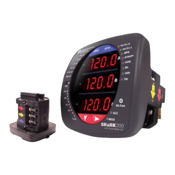
Page 31: Meter Overview And Specifications
IEC 61850 network. For detailed information on this option, see Appendix E: Using the IEC 61850 Protocol Ethernet Network Card (INP300S) on page E-1. Electro Industries/GaugeTech Electro Industries/GaugeTech E149701 The Leader In Power Monitoring and Smart Grid Solutions... - Page 32 Features of the Shark® 200 meter include: • 0.2% Class revenue certifiable energy and demand metering • Meets ANSI C12.20 (0.2%) and IEC 62053-22 (0.2%) classes Electro Industries/GaugeTech Electro Industries/GaugeTech E149701 The Leader In Power Monitoring and Smart Grid Solutions...
- Page 33 • Transformer/Line Loss compensation (see Chapter 8 and Appendix A in the Com- municator EXT 4.0 and MeterManager EXT Software User Manual for instructions on using this feature*) Electro Industries/GaugeTech Electro Industries/GaugeTech E149701 The Leader In Power Monitoring and Smart Grid Solutions...
- Page 34 DIN Rail mounting (see 3.4: Transducer Installation on page 3-6, for Shark® 200T transducer mounting information). Figure 2.2: Shark® 200 Transducer Electro Industries/GaugeTech Electro Industries/GaugeTech E149701 The Leader In Power Monitoring and Smart Grid Solutions The Leader In Power Monitoring and Smart Grid Solutions...
-
Page 35: Voltage And Current Inputs
Shark200 - 60 - 10- V2- D -INP100S - X 1. Model: Shark® 200 Meter/Transducer Shark® 200T Transducer (no display) 2. Frequency: 50: 50 Hz System Electro Industries/GaugeTech Electro Industries/GaugeTech E149701 The Leader In Power Monitoring and Smart Grid Solutions The Leader In Power Monitoring and Smart Grid Solutions... - Page 36 X: None INP100S: 10/100BaseT Ethernet RO1S: 2 Relay outputs/2 Status inputs PO1S: 4 Pulse outputs/4 Status inputs Electro Industries/GaugeTech Electro Industries/GaugeTech E149701 The Leader In Power Monitoring and Smart Grid Solutions The Leader In Power Monitoring and Smart Grid Solutions...
- Page 37 (Shark® 200 meter with 60 Hz System, 5 A Secondary, V-2 V-Switch key, 18-60 V DC power supply, 10/100BaseT Ethernet in Card Slot 1 and no card in Card Slot 2) Electro Industries/GaugeTech Electro Industries/GaugeTech E149701 The Leader In Power Monitoring and Smart Grid Solutions...
- Page 38 Communicator EXT Device Status screen (from the Communicator EXT Main screen, click Tools>Device Status). Electro Industries/GaugeTech Electro Industries/GaugeTech E149701 The Leader In Power Monitoring and Smart Grid Solutions The Leader In Power Monitoring and Smart Grid Solutions...
- Page 39 NOTE: For more details on software configuration, refer to the Communicator EXT 4.0 and MeterManager EXT Software User Manual. Electro Industries/GaugeTech Electro Industries/GaugeTech E149701 The Leader In Power Monitoring and Smart Grid Solutions...
-
Page 40: Measured Values
Frequency Harmonics to the 40th Order Voltage Angles Current Angles % of Load Bar Waveform Scope Electro Industries/GaugeTech Electro Industries/GaugeTech E149701 2-10 The Leader In Power Monitoring and Smart Grid Solutions The Leader In Power Monitoring and Smart Grid Solutions... -
Page 41: Utility Peak Demand
Utility Demand features can be used to calculate Watt, VAR, VA and PF readings. Voltage provides an instantaneous Max and Min reading which displays the highest surge and lowest sag seen by the meter. All other parameters offer Max and Min capability over the user-selectable averaging period. Electro Industries/GaugeTech Electro Industries/GaugeTech E149701 2-11... -
Page 42: Specifications
Pickup Voltage: 20 V AC Connection: 7 Pin 0.400” Pluggable Terminal Block AWG#12 -26/ (0.129 -3.31) mm Electro Industries/GaugeTech Electro Industries/GaugeTech E149701 2-12 The Leader In Power Monitoring and Smart Grid Solutions The Leader In Power Monitoring and Smart Grid Solutions... - Page 43 Programmable Full Scale to any CT ratio Continuous Current Withstand: 20 A for screw terminated or pass through connections Electro Industries/GaugeTech Electro Industries/GaugeTech E149701 2-13 The Leader In Power Monitoring and Smart Grid Solutions The Leader In Power Monitoring and Smart Grid Solutions...
- Page 44 1µA@350 V Isolation: AC 3750 V Reset state: (NC - C) Closed; (NO - C) Open Electro Industries/GaugeTech Electro Industries/GaugeTech E149701 2-14 The Leader In Power Monitoring and Smart Grid Solutions The Leader In Power Monitoring and Smart Grid Solutions...
- Page 45 Watt IR LED Light Pulses Through face plate 90ms 90ms KYZ output Contact States Through Backplate Electro Industries/GaugeTech Electro Industries/GaugeTech E149701 2-15 The Leader In Power Monitoring and Smart Grid Solutions The Leader In Power Monitoring and Smart Grid Solutions...
- Page 46 Communication Standard: 1. RS485 port through backplate 2. IrDA port through faceplate 3. Energy pulse output through backplate and Infrared LED through faceplate Electro Industries/GaugeTech Electro Industries/GaugeTech E149701 2-16 The Leader In Power Monitoring and Smart Grid Solutions The Leader In Power Monitoring and Smart Grid Solutions...
-
Page 47: Compliance
• CE (EN61326-1, FCC Part 15, Subpart B, Class A) • IEC 62053-22 (0.2% Class) • ANSI C12.20 (0.2% Accuracy) • ANSI (IEEE) C37.90.1 Surge Withstand Electro Industries/GaugeTech Electro Industries/GaugeTech E149701 2-17 The Leader In Power Monitoring and Smart Grid Solutions... - Page 48 • EN61000-6-2 Immunity for Industrial Environments: 2005 • EN61000-6-4 Emission Standards for Industrial Environments: 2007 • EN61326 EMC Requirements: 2006 • KEMA Certified IEC 61850 Electro Industries/GaugeTech Electro Industries/GaugeTech E149701 2-18 The Leader In Power Monitoring and Smart Grid Solutions...
-
Page 49: Accuracy
2: Meter Overview and Specifications 2.4: Accuracy (For full Range specifications see 2.2: Specifications on page 2-12.) Shark 200 Clock Accuracy: Max. +/-2 seconds per day at 25 For 23 C, 3 Phase balanced Wye or Delta load, at 50 or 60 Hz (as per order), 5 A... - Page 50 0.2%. See hookup diagrams 8, 9, and 10 in 4.8: Electrical Connection Diagrams on page 4-8. At least one Voltage input (minimum 20 V AC) must be connected for THD measurement on current channels. Electro Industries/GaugeTech Electro Industries/GaugeTech E149701 2-20...
-
Page 51: Mechanical Installation
4.85 [12.32] 5.02 [12.75] 0.95 [2.41] 3.25 [8.26] 0.77 [1.95] Figure 3.1: Meter Front and Side Dimensions Electro Industries/GaugeTech Electro Industries/GaugeTech E149701 The Leader In Power Monitoring and Smart Grid Solutions The Leader In Power Monitoring and Smart Grid Solutions... - Page 52 0.77 [1.95] ® Figure 3.2: Shark 200T Dimensions 3.56 [9.04] 3.56 [9.04] Figure 3.3: Meter Back Dimensions Electro Industries/GaugeTech Electro Industries/GaugeTech E149701 The Leader In Power Monitoring and Smart Grid Solutions The Leader In Power Monitoring and Smart Grid Solutions...
-
Page 53: Ansi Installation Steps
(see Environmental specifications in 2.2: Specifications on page 2-12). 3.2: ANSI Installation Steps 1. Slide meter with Mounting Gasket into panel. Electro Industries/GaugeTech Electro Industries/GaugeTech E149701 The Leader In Power Monitoring and Smart Grid Solutions... -
Page 54: Din Installation Steps
1. Slide meter with NEMA 12 Mounting Gasket into panel (remove ANSI Studs, if in place). 2. From back of panel, slide 2 DIN Mounting Brackets into grooves in top and bottom of meter housing. Snap into place. Electro Industries/GaugeTech Electro Industries/GaugeTech E149701 The Leader In Power Monitoring and Smart Grid Solutions... - Page 55 Remove (unscrew) ANSI studs for DIN installation DIN mounting Bottom bracket mounting bracket groove Figure 3.6: DIN Installation Electro Industries/GaugeTech Electro Industries/GaugeTech E149701 The Leader In Power Monitoring and Smart Grid Solutions The Leader In Power Monitoring and Smart Grid Solutions...
-
Page 56: Transducer Installation
PVC, stainless steel and copper. Release Clip Figure 3.7: Transducer on DIN Rail Electro Industries/GaugeTech Electro Industries/GaugeTech E149701 The Leader In Power Monitoring and Smart Grid Solutions... - Page 57 3: Mechanical Installation Black Rubber Stoppers Release Clip Figure 3.8: DIN Rail Detail Electro Industries/GaugeTech Electro Industries/GaugeTech E149701 The Leader In Power Monitoring and Smart Grid Solutions The Leader In Power Monitoring and Smart Grid Solutions...
- Page 58 3: Mechanical Installation This page intentionally left blank. Electro Industries/GaugeTech Electro Industries/GaugeTech E149701 The Leader In Power Monitoring and Smart Grid Solutions The Leader In Power Monitoring and Smart Grid Solutions...
-
Page 59: Electrical Installation
NOTE: The current inputs are only to be connected to external current transformers provided by the installer. The CTs shall be Approved or Certified and rated for the current of the meter used. Electro Industries/GaugeTech Electro Industries/GaugeTech E149701 The Leader In Power Monitoring and Smart Grid Solutions... - Page 60 Shark® 200 doit être enlevée du service. Un côté du transformateur de courant doit être mis à terre. Electro Industries/GaugeTech Electro Industries/GaugeTech E149701...
- Page 61 DANS L'UTILISATION FINALE DE L'ÉQUIPEMENT OU L'INSTALLATION. L'INTERRUPTEUR DOIT ÊTRE DANS UNE PROXIMITÉ PROCHE DE L'ÉQUIPEMENT ET A LA PORTÉE DE L'OPÉRATEUR. L'INTERRUPTEUR DOIT AVOIR LA MENTION DÉBRANCHEMENT DE L'APPAREIL POUR L'ÉQUIPEMENT. Electro Industries/GaugeTech Electro Industries/GaugeTech E149701 The Leader In Power Monitoring and Smart Grid Solutions...
-
Page 62: Ct Leads Terminated To Meter
Figure 4.1: CT Leads Terminated to Meter, #8 Screw for Lug Connection Wiring Diagrams are shown in Section 4.8 of this chapter. Communications connections are detailed in Chapter 5. Electro Industries/GaugeTech Electro Industries/GaugeTech E149701 The Leader In Power Monitoring and Smart Grid Solutions... -
Page 63: Ct Leads Pass Through (No Meter Termination)
In this case, remove the current gills and place the CT wire directly through the CT opening. The opening accommodates up to 0.177” / 4.5mm maximum diameter CT wire. Figure 4.2: Pass Through Wire Electrical Connection Electro Industries/GaugeTech Electro Industries/GaugeTech E149701 The Leader In Power Monitoring and Smart Grid Solutions... -
Page 64: Quick Connect Crimp-On Terminations
For quick termination or for portable applications, 0.25” quick connect crimp-on connectors can also be used Quick connect crimp-on terminations Figure 4.3: Quick Connect Electrical Connection Electro Industries/GaugeTech Electro Industries/GaugeTech E149701 The Leader In Power Monitoring and Smart Grid Solutions The Leader In Power Monitoring and Smart Grid Solutions... -
Page 65: Voltage And Power Supply Connections
EIG offers the EI-CP Panel meter protective fuse kit, which can be ordered from EIG’s webstore: www.electroind.com/store. Select Fuse Kits from the list on the left side of the webpage. Electro Industries/GaugeTech Electro Industries/GaugeTech E149701 The Leader In Power Monitoring and Smart Grid Solutions... -
Page 66: Electrical Connection Diagrams
7. Three-Phase, Three-Wire Delta with 2 PTs, 3 CTs 8. Current Only Measurement (Three Phase) 9. Current Only Measurement (Dual Phase) 10.Current Only Measurement (Single Phase) Electro Industries/GaugeTech Electro Industries/GaugeTech E149701 The Leader In Power Monitoring and Smart Grid Solutions... - Page 67 3 x 0.1A LOAD Select: “ 3 EL WYE ” (3 Element Wye) from the Shark® meter’s front panel display (see Chapter 6). Electro Industries/GaugeTech Electro Industries/GaugeTech E149701 The Leader In Power Monitoring and Smart Grid Solutions The Leader In Power Monitoring and Smart Grid Solutions...
- Page 68 FUSES 2 x 0.1A LOAD Select: “ 3 EL WYE ” (3 Element Wye) from the Shark® meter’s Front Panel Display (see Chapter 6). Electro Industries/GaugeTech Electro Industries/GaugeTech E149701 4-10 The Leader In Power Monitoring and Smart Grid Solutions The Leader In Power Monitoring and Smart Grid Solutions...
- Page 69 FUSE 0.1A LOAD Select: “ 3 EL WYE ” (3 Element Wye) from the Shark® meter’s Front Panel Display (see Chapter 6). Electro Industries/GaugeTech Electro Industries/GaugeTech E149701 4-11 The Leader In Power Monitoring and Smart Grid Solutions The Leader In Power Monitoring and Smart Grid Solutions...
- Page 70 FUSES 2 x 0.1A LOAD Select: “2.5 EL WYE” (2.5 Element Wye) from the Shark® meter’s front panel display (see Chapter 6). Electro Industries/GaugeTech Electro Industries/GaugeTech E149701 4-12 The Leader In Power Monitoring and Smart Grid Solutions The Leader In Power Monitoring and Smart Grid Solutions...
- Page 71 3 x 0.1A Earth Ground LOAD Select: “3 EL WYE” (3 Element Wye) from the Shark® meter’s front panel display (see Chapter 6). Electro Industries/GaugeTech Electro Industries/GaugeTech E149701 4-13 The Leader In Power Monitoring and Smart Grid Solutions The Leader In Power Monitoring and Smart Grid Solutions...
- Page 72 2 x 0.1A Earth Ground LOAD Select: “2.5 EL WYE” (2.5 Element Wye) from the Shark® meter’s front panel display (see Chapter 6). Electro Industries/GaugeTech Electro Industries/GaugeTech E149701 4-14 The Leader In Power Monitoring and Smart Grid Solutions The Leader In Power Monitoring and Smart Grid Solutions...
- Page 73 3 x 0.1A LOAD Select: “2 CT DEL” (2 CT Delta) from the Shark® meter’s front panel display (see Chapter 6). Not connected to meter Electro Industries/GaugeTech Electro Industries/GaugeTech E149701 4-15 The Leader In Power Monitoring and Smart Grid Solutions...
- Page 74 Earth Ground LOAD Select: “2 CT DEL” (2 CT Delta) from the Shark® meter’s front panel display (see Chapter 6). Not connected to meter Electro Industries/GaugeTech Electro Industries/GaugeTech E149701 4-16 The Leader In Power Monitoring and Smart Grid Solutions The Leader In Power Monitoring and Smart Grid Solutions...
- Page 75 Select: “2 CT DEL” (2 CT Delta) from the Shark® meter’s front panel display (see Chapter 6). NOTE: The third CT for hookup is optional, and is used only for Current measurement. Not connected to meter Electro Industries/GaugeTech Electro Industries/GaugeTech E149701 4-17 The Leader In Power Monitoring and Smart Grid Solutions...
- Page 76 Select: “3 EL WYE” (3 Element Wye) from the Shark® meter’s front panel display (see Chapter 6.) NOTE: Even if the meter is used only for current measurement, an AN reference is recommended for improved accuracy. Electro Industries/GaugeTech Electro Industries/GaugeTech E149701 4-18...
- Page 77 Select: “3 EL WYE” (3 Element Wye) from the Shark® meter’s front panel display (see Chapter 6). NOTE: Even if the meter is used only for current measurement, an AN reference is recommended for improved accuracy. Electro Industries/GaugeTech Electro Industries/GaugeTech E149701 4-19...
- Page 78 • Even if the meter is used only for current measurement, an AN reference is recom- mended for improved accuracy. • The diagram shows a connection to Phase A, but you can also connect to Phase B or Phase C. Electro Industries/GaugeTech Electro Industries/GaugeTech E149701 4-20...
-
Page 79: Extended Surge Protection For Substation Instrumentation
EI-MSB10-400 EI-MSB10-400 EI-MSB10-400 EI-MSB10-400 Figure 4.5: Wiring Schematic for Extended Surge Suppression Suitable for Substation Instrumentation Electro Industries/GaugeTech Electro Industries/GaugeTech E149701 4-21 The Leader In Power Monitoring and Smart Grid Solutions The Leader In Power Monitoring and Smart Grid Solutions... - Page 80 4: Electrical Installation This page intentionally left blank. Electro Industries/GaugeTech Electro Industries/GaugeTech E149701 4-22 The Leader In Power Monitoring and Smart Grid Solutions The Leader In Power Monitoring and Smart Grid Solutions...
-
Page 81: Communication Installation
Com 2 provides a combination RS485 and an Energy Pulse Output (KYZ pulse). See 2.2: Specifications on page 2-12, for the KYZ Output specifications; see 6.4: Per- forming Watt Hour Accuracy Testing (Verification) on page 6-17, for pulse constants. Electro Industries/GaugeTech Electro Industries/GaugeTech E149701... - Page 82 As shown in Figure 5.2, to connect a Shark® 200 meter to a PC, you need to use an RS485 to RS232 converter, such as EIG’s Unicom 2500. See 5.1.2.1: Using the Unicom 2500 on page 5-5, for additional information. Electro Industries/GaugeTech Electro Industries/GaugeTech E149701...
- Page 83 4000 feet (1219.20 meters). • Connect shield to RS485 Master and individual devices as shown in Figure 5.4. You may also connect the shield to earth-ground at one point. Electro Industries/GaugeTech Electro Industries/GaugeTech E149701 The Leader In Power Monitoring and Smart Grid Solutions...
- Page 84 Slave device 4 Twisted pair, shielded (SH) cable Twisted pair, shielded (SH) cable Figure 5.5: Incorrect “T” and “Star” Topologies Electro Industries/GaugeTech Electro Industries/GaugeTech E149701 The Leader In Power Monitoring and Smart Grid Solutions The Leader In Power Monitoring and Smart Grid Solutions...
-
Page 85: Using The Unicom 2500
Short TX(-) to RX(-) becomes (-) signal Short TX(+) to RX(+) becomes (+) signal 120.00 120.00 120.00 Figure 5.6: Unicom 2500 with Connections Electro Industries/GaugeTech Electro Industries/GaugeTech E149701 The Leader In Power Monitoring and Smart Grid Solutions The Leader In Power Monitoring and Smart Grid Solutions... -
Page 86: Using The Rs485 To Usb Communication Converter
PC serial emulation port. The converter’s model number is E205301, and it can be ordered from EIG’s web- store: www.electroind.com/store. Electro Industries/GaugeTech Electro Industries/GaugeTech E149701 The Leader In Power Monitoring and Smart Grid Solutions... -
Page 87: And Programming Overview
Figure 5.1. Once a connection is established, Communicator EXT software can be used to program the meter and communicate to Shark® 200T transducer slave devices. Electro Industries/GaugeTech Electro Industries/GaugeTech E149701 The Leader In Power Monitoring and Smart Grid Solutions The Leader In Power Monitoring and Smart Grid Solutions... -
Page 88: Accessing The Meter In Default Communication Mode
IMPORTANT! In Normal operating mode the initial factory communication settings are: Baud Rate: 57600 Address: Protocol: Modbus RTU Electro Industries/GaugeTech Electro Industries/GaugeTech E149701 The Leader In Power Monitoring and Smart Grid Solutions The Leader In Power Monitoring and Smart Grid Solutions... - Page 89 4. Click the Connect button. If you have a problem connecting, you may have to disconnect power to the meter, then reconnect power and click the Connect button, again. Electro Industries/GaugeTech Electro Industries/GaugeTech E149701 The Leader In Power Monitoring and Smart Grid Solutions...
- Page 90 6. Click the Profile icon in the Menu Bar. 7. You will see the Shark® 200 meter’s Device Profile screen. The menu on the left side of the screen lets you navigate between Settings screens (see below). Electro Industries/GaugeTech Electro Industries/GaugeTech E149701...
- Page 91 Click the Optimal Scaling button to have the software choose a divisor for voltage, current, and power, that will not result in an over/under-range. NOTE: You must set the DNP polling software to multiply by the divisor amount before showing the final value. Electro Industries/GaugeTech Electro Industries/GaugeTech E149701 5-11...
- Page 92 9. Click Exit to leave the Device Profile or click other menu items to change other aspects of the Device Profile (see 5.2.2.1: Shark® 200 Meter Device Profile Set- tings on page 5-13, for instructions). Electro Industries/GaugeTech Electro Industries/GaugeTech E149701...
-
Page 93: Shark® 200 Meter Device Profile Settings
Update CT/Update PT buttons to let the software calculate the Numerator, Denominator, and Multiplier for you. You can then empty the Ratio fields and click the Update Ratio buttons to confirm the calculated settings: you will see the same ratios you initially entered. Electro Industries/GaugeTech Electro Industries/GaugeTech E149701 5-13... - Page 94 CT Multiplier The Current Full Scale field will read 2000. NOTE: You can obtain the same Current Full Scale by entering a CT Numerator of 200 and a CT Multiplier of 10. Electro Industries/GaugeTech Electro Industries/GaugeTech E149701 5-14 The Leader In Power Monitoring and Smart Grid Solutions...
- Page 95 345,000/115 Volts: Pt-n value is 3450, Pt-d value is 115, Pt-Multiplier value is 100 345,000/69 Volts: Pt-n value is 345, Pt-d value is 69, Pt-Multiplier value is 1000 NOTE: Settings are the same for Wye and Delta configurations. Electro Industries/GaugeTech Electro Industries/GaugeTech E149701...
- Page 96 You must select at least one reading. Power Direction: View as Load or View as Generator; this controls how energy is accumulated in the Shark® meter. View as Load means the energy readings are accu- Electro Industries/GaugeTech Electro Industries/GaugeTech E149701...
- Page 97 There is the IEEE/IEC method and the Shark® meter’s legacy method. They are both readily available by selecting the appropriate programmable setting. The next two pages show examples of the result of choosing either method. Electro Industries/GaugeTech Electro Industries/GaugeTech E149701 5-17...
- Page 98 +P, +Wh -P, -Wh Delivered Received Delivered Received Lead Lead +Q, +VARh +Q, +VARh Delivered Delivered Electro Industries/GaugeTech Electro Industries/GaugeTech E149701 5-18 The Leader In Power Monitoring and Smart Grid Solutions The Leader In Power Monitoring and Smart Grid Solutions...
- Page 99 Legacy mode Received View as Generator +P, -Wh -P, +Wh Received Delivered Lead Lead -Q, -VARh Delivered Electro Industries/GaugeTech Electro Industries/GaugeTech E149701 5-19 The Leader In Power Monitoring and Smart Grid Solutions The Leader In Power Monitoring and Smart Grid Solutions...
- Page 100 Enable Fixed Scale for Voltage Display. The screen changes - see the figure below. Select the scaling you want to use from the pull-down menu. The options are: 0, 100.0 kV, 10.00 kV, or 0 kV. Electro Industries/GaugeTech Electro Industries/GaugeTech E149701 5-20...
- Page 101 Power Settings Power Scale: Auto; unit; kilo (K); Mega (M) Apparent Power (VA) Calculation Method: Arithmetic Sum; Vector Sum Demand Averaging Type: Block or Rolling Electro Industries/GaugeTech Electro Industries/GaugeTech E149701 5-21 The Leader In Power Monitoring and Smart Grid Solutions...
- Page 102 Yes or No. NOTES: • If you enable a password for reset, you must also enable it for configuration. • The meter’s default is password disabled. Electro Industries/GaugeTech Electro Industries/GaugeTech E149701 5-22 The Leader In Power Monitoring and Smart Grid Solutions...
- Page 103 Change. Enter the old password and click OK to proceed with the password change. • Change the Meter Identification: input a new meter label into the Meter Designation field. Electro Industries/GaugeTech Electro Industries/GaugeTech E149701 5-23 The Leader In Power Monitoring and Smart Grid Solutions...
- Page 104 Limits for the Shark® 200 meter. To set up a Limit: 1. Select a Limit by double-clicking on the Assigned Channel field. 2. You will see the screen shown below. Select a Group and an Item for the Limit. Electro Industries/GaugeTech Electro Industries/GaugeTech E149701 5-24...
- Page 105 TIME MEASURED VALUE (if applicable) Primary Fields: These fields are display only. They show what the setpoint and return hysteresis value are for each limit. Electro Industries/GaugeTech Electro Industries/GaugeTech E149701 5-25 The Leader In Power Monitoring and Smart Grid Solutions...
- Page 106 From the Tree Menu, click General Settings>Time Settings. Check the box to Enable Daylight Savings time, or un-check it to Disable Daylight Savings Time. Electro Industries/GaugeTech Electro Industries/GaugeTech E149701 5-26 The Leader In Power Monitoring and Smart Grid Solutions...
- Page 107 User Manual for instructions. Use these fields to set up Line Frequency clock synchronization: Under Clock Sync select: • Yes from the Enable pull-down menu Electro Industries/GaugeTech Electro Industries/GaugeTech E149701 5-27 The Leader In Power Monitoring and Smart Grid Solutions...
- Page 108 Transformer and Line Loss Compensation, CT and PT Compensation, Option card configuration, Secondary Voltage display, Symmetrical Components, Voltage and Current Unbalance, and scaling Primary readings for use with DNP. Electro Industries/GaugeTech Electro Industries/GaugeTech E149701 5-28 The Leader In Power Monitoring and Smart Grid Solutions...
-
Page 109: Using The Shark® 200 Meter
• % of Load bar: Graphic Display of Amps as % of the load (see 6.3: Understanding the % of Load Bar on page 6-16, for additional information) • IrDA Communication port: Com 1 port for wireless communication Electro Industries/GaugeTech Electro Industries/GaugeTech E149701... -
Page 110: Understanding Meter Face Buttons
• Perform LED Checks • Change settings • View parameter values • Scroll parameter values • View Limit states Electro Industries/GaugeTech Electro Industries/GaugeTech E149701 The Leader In Power Monitoring and Smart Grid Solutions The Leader In Power Monitoring and Smart Grid Solutions... -
Page 111: Using The Front Panel
The Kilo or Mega LED lights, showing the scale for the Wh, VARh and VAh readings. Figure 6.3 shows an example of a Wh reading. Electro Industries/GaugeTech Electro Industries/GaugeTech E149701 The Leader In Power Monitoring and Smart Grid Solutions... -
Page 112: Using The Main Menu
MENU ENTER For example: Press Down Twice - CFG moves to A window. Press Down Twice - OPr moves to window. Electro Industries/GaugeTech Electro Industries/GaugeTech E149701 The Leader In Power Monitoring and Smart Grid Solutions The Leader In Power Monitoring and Smart Grid Solutions... -
Page 113: Using Reset Mode
CAUTION! Reset Demand YES resets all Max and Min values. 2. Once you have performed a reset, the screen displays either “rSt dMd donE” or “rSt EnEr donE”and then resumes auto-scrolling parameters. Electro Industries/GaugeTech Electro Industries/GaugeTech E149701 The Leader In Power Monitoring and Smart Grid Solutions... -
Page 114: Entering A Password
Reset mode. • The previous Operating mode screen is redisplayed, if you are in Configuration mode. Electro Industries/GaugeTech Electro Industries/GaugeTech E149701 The Leader In Power Monitoring and Smart Grid Solutions The Leader In Power Monitoring and Smart Grid Solutions... -
Page 115: Using Configuration Mode
6. The parameter screen appears, showing the current settings. To change the settings: • Use either the Down button or the Right button to select an option. Electro Industries/GaugeTech Electro Industries/GaugeTech E149701 The Leader In Power Monitoring and Smart Grid Solutions... - Page 116 The settings have been the settings. Press the Right Cancel the Save. saved. button for Stor All no screen. Electro Industries/GaugeTech Electro Industries/GaugeTech E149701 The Leader In Power Monitoring and Smart Grid Solutions The Leader In Power Monitoring and Smart Grid Solutions...
-
Page 117: Configuring The Scroll Feature
• To return to the Main Menu screen, press the Menu button twice. • To return to the scrolling (or non-scrolling) parameters display, press the Menu button three times. Electro Industries/GaugeTech Electro Industries/GaugeTech E149701 The Leader In Power Monitoring and Smart Grid Solutions... -
Page 118: Configuring Ct Setting
800/5 A: Set the Ct-n value for 800 and the Ct-S value for 1. 2,000/5 A: Set the Ct-n value for 2000 and the Ct-S value for 1. 10,000/5 A: Set the Ct-n value for 1000 and the Ct-S value for 10. Electro Industries/GaugeTech Electro Industries/GaugeTech E149701... -
Page 119: Configuring Pt Setting
From the Pt-S screen, use the Right button or the Down button to choose the scaling you want. The Pt-S setting can be 1, 10, 100, or 1000. NOTE: If you are prompted to enter a password, refer to Section 6.2.4 for instruc- tions on doing so. Electro Industries/GaugeTech Electro Industries/GaugeTech E149701 6-11... - Page 120 MENU ENTER Use buttons to set Pt-n Use buttons to set Pt-d Use buttons to select scaling Electro Industries/GaugeTech Electro Industries/GaugeTech E149701 6-12 The Leader In Power Monitoring and Smart Grid Solutions The Leader In Power Monitoring and Smart Grid Solutions...
-
Page 121: Configuring Connection Setting
• Enter the address. • Access one of the other Port screens by pressing the Enter button: press Enter once to access the bAUd screen (Baud Rate), twice to access the Prot screen (Protocol). Electro Industries/GaugeTech Electro Industries/GaugeTech E149701 6-13... - Page 122 ENTER MENU ENTER Use buttons to enter Address Use buttons to select Baud Rate Use buttons to select Protocol Electro Industries/GaugeTech Electro Industries/GaugeTech E149701 6-14 The Leader In Power Monitoring and Smart Grid Solutions The Leader In Power Monitoring and Smart Grid Solutions...
-
Page 123: Using Operating Mode
VAR hour Q3,4 VAR hour net VAR hour total Reactive Energy Display VA hour Apparent Energy Display Electro Industries/GaugeTech Electro Industries/GaugeTech E149701 6-15 The Leader In Power Monitoring and Smart Grid Solutions The Leader In Power Monitoring and Smart Grid Solutions... -
Page 124: Understanding The % Of Load Bar
The % of Load bar can be programmed through Communicator EXT software - see Chapter 8 in the Communicator EXT 4.0 and MeterManager EXT Software User Manual, for instructions. Electro Industries/GaugeTech Electro Industries/GaugeTech E149701 6-16 The Leader In Power Monitoring and Smart Grid Solutions... -
Page 125: Performing Watt-Hour Accuracy Testing (Verification)
90%- test pulse 60%- Wh Pulse 30%- KILO MEGA %LOAD Figure 6.4: Watt Hour Test Pulse Electro Industries/GaugeTech Electro Industries/GaugeTech E149701 6-17 The Leader In Power Monitoring and Smart Grid Solutions The Leader In Power Monitoring and Smart Grid Solutions... - Page 126 Standard's internal pulse. You must program the test pulse value (Kh) into the Standard for the results to be accurate. Electro Industries/GaugeTech Electro Industries/GaugeTech E149701...
- Page 127 11. Repeat steps 5 through 10 until all test pulses are checked. 12. De-energize all circuits and remove power from the Standard, sources, and the Shark® 200 meter. 13. Disconnect all connections from the Shark® 200 meter. Electro Industries/GaugeTech Electro Industries/GaugeTech E149701 6-19...
- Page 128 6: Using the Shark® 200 Meter This page intentionally left blank. Electro Industries/GaugeTech Electro Industries/GaugeTech E149701 6-20 The Leader In Power Monitoring and Smart Grid Solutions The Leader In Power Monitoring and Smart Grid Solutions...
- Page 129 Total Solutions Option Card Slots Figure 7.1: Shark® 200 Meter Back, Showing Option Card Slots and I/O Card Electro Industries/GaugeTech Electro Industries/GaugeTech E149701 The Leader In Power Monitoring and Smart Grid Solutions The Leader In Power Monitoring and Smart Grid Solutions...
-
Page 130: Using The I/O Option Cards
4. Securely re-fasten the screws at the top and bottom of the card. CAUTIONS! • Make sure the I/O card is inserted properly into the track to avoid damaging the card’s components. Electro Industries/GaugeTech Electro Industries/GaugeTech E149701 The Leader In Power Monitoring and Smart Grid Solutions... - Page 131 Option card 2 c. Detachable terminal block 1 d. Detachable terminal block 2 e. Communication connection for Port 2 Electro Industries/GaugeTech Electro Industries/GaugeTech E149701 The Leader In Power Monitoring and Smart Grid Solutions The Leader In Power Monitoring and Smart Grid Solutions...
-
Page 132: Configuring Option Cards
@ ± 1mA Temperature coefficient ± 30 nA/ °C Isolation: AC 2500 V system to outputs Electro Industries/GaugeTech Electro Industries/GaugeTech E149701 The Leader In Power Monitoring and Smart Grid Solutions The Leader In Power Monitoring and Smart Grid Solutions... -
Page 133: Default Configuration:
Phase A Voltage WYE, 300 Volts => +1 mA Phase A Voltage Delta, 600 Volts => +1 mA Channel 4 Phase A Current, 10 A => +1 mA Electro Industries/GaugeTech Electro Industries/GaugeTech E149701 The Leader In Power Monitoring and Smart Grid Solutions... -
Page 134: Wiring Diagram
Outputs Outputs (1,2,3,4) 0-1 mA Channel Common (C) Figure 7.3: 4-Channel 0 - 1 mA Output Card Electro Industries/GaugeTech Electro Industries/GaugeTech E149701 The Leader In Power Monitoring and Smart Grid Solutions The Leader In Power Monitoring and Smart Grid Solutions... -
Page 135: Ma Output Card (20Maos)
28 V DC max. Internal voltage drop: 3.4 V DC @ 24 mA Reset/Default output value: 12 mA Electro Industries/GaugeTech Electro Industries/GaugeTech E149701 The Leader In Power Monitoring and Smart Grid Solutions The Leader In Power Monitoring and Smart Grid Solutions... -
Page 136: Default Configuration
Phase A Voltage Delta, 600 Volts => 20 mA Channel 4 Phase A Current, 10 A => 20 mA 0 Phase A Current, 0 A => 4 mA Electro Industries/GaugeTech Electro Industries/GaugeTech E149701 The Leader In Power Monitoring and Smart Grid Solutions... - Page 137 Outputs (1,2,3,4) Outputs 4-20 mA Channel Loop Common (C) Figure 7.4: 4-Channel 0 - 20 mA Output Card Electro Industries/GaugeTech Electro Industries/GaugeTech E149701 The Leader In Power Monitoring and Smart Grid Solutions The Leader In Power Monitoring and Smart Grid Solutions...
-
Page 138: Digital Output (Relay Contact) / Digital Input Card (Ro1S)
Number of Inputs: Sensing type: Wet or dry contact status detection Wetting voltage: DC (12-24) V, internally generated Electro Industries/GaugeTech Electro Industries/GaugeTech E149701 7-10 The Leader In Power Monitoring and Smart Grid Solutions The Leader In Power Monitoring and Smart Grid Solutions... - Page 139 Dimensions (inch) W x H x L: 0.72 x 2.68 x 3.26 External Connection: AWG 12-26/(0.129 - 3.31) mm 9 pin, 0.200” pluggable terminal block Electro Industries/GaugeTech Electro Industries/GaugeTech E149701 7-11 The Leader In Power Monitoring and Smart Grid Solutions...
- Page 140 Inputs (I1,I2) Relay Outputs Common (C) Figure 7.5: Relay Contact (2) / Status Input (2) Card Electro Industries/GaugeTech Electro Industries/GaugeTech E149701 7-12 The Leader In Power Monitoring and Smart Grid Solutions The Leader In Power Monitoring and Smart Grid Solutions...
-
Page 141: Pulse Output (Solid State Relay Contacts Digital Input Card (P01S)
Wet or dry contact status detection Wetting voltage: DC (12-24) V, internally generated Input current: 2.5 mA – constant current regulated Electro Industries/GaugeTech Electro Industries/GaugeTech E149701 7-13 The Leader In Power Monitoring and Smart Grid Solutions The Leader In Power Monitoring and Smart Grid Solutions... - Page 142 Defaulted to Energy Pulses Pulse Channel 1 1.8 +Watt-hours per pulse Pulse Channel 2 1.8 -Watt-hours per pulse Electro Industries/GaugeTech Electro Industries/GaugeTech E149701 7-14 The Leader In Power Monitoring and Smart Grid Solutions The Leader In Power Monitoring and Smart Grid Solutions...
- Page 143 Inputs (I1,I2) Pulse Outputs Common (C) Figure 7.6: Pulse Output (4) / Status Input (4) Card Electro Industries/GaugeTech Electro Industries/GaugeTech E149701 7-15 The Leader In Power Monitoring and Smart Grid Solutions The Leader In Power Monitoring and Smart Grid Solutions...
-
Page 144: Fiber Optic Communication Card (Fosts; Fovps)
EN61000-4-2 Weight: 1.2 oz Dimensions (inch) W x H x L: 0.72 x 2.68 x 3.26 Electro Industries/GaugeTech Electro Industries/GaugeTech E149701 7-16 The Leader In Power Monitoring and Smart Grid Solutions The Leader In Power Monitoring and Smart Grid Solutions... - Page 145 Chain Switch to ON. This allows messages not for this meter to continue to the next meter in sequence. Figure 7.7: Fiber Optic Communication Card Electro Industries/GaugeTech Electro Industries/GaugeTech E149701 7-17 The Leader In Power Monitoring and Smart Grid Solutions...
-
Page 146: Baset Ethernet Communication Card (Inp100S)
Dimensions (inch) W x H x L: 0.72 x 2.68 x 3.26 Connection Type: RJ45 modular (auto-detecting transmit and receive) Electro Industries/GaugeTech Electro Industries/GaugeTech E149701 7-18 The Leader In Power Monitoring and Smart Grid Solutions The Leader In Power Monitoring and Smart Grid Solutions... - Page 147 Because of this, when you are communicating directly to a meter with a PC or a switch, a straight cable can be used. Electro Industries/GaugeTech Electro Industries/GaugeTech E149701 7-19...
-
Page 148: Iec 61850 Protocol Ethernet Network Card (Inp300S)
Dimensions (inch) W x H x L: 0.72 x 2.68 x 3.26 Connection Type: RJ45 modular (auto-detecting transmit and receive) Electro Industries/GaugeTech Electro Industries/GaugeTech E149701 7-20 The Leader In Power Monitoring and Smart Grid Solutions The Leader In Power Monitoring and Smart Grid Solutions... - Page 149 Because of this, when you are communicating directly to a meter with a PC or a switch, a straight cable can be used. Electro Industries/GaugeTech Electro Industries/GaugeTech E149701 7-21...
- Page 150 7: Using the I/O Option Cards This page intentionally left blank. Electro Industries/GaugeTech Electro Industries/GaugeTech E149701 7-22 The Leader In Power Monitoring and Smart Grid Solutions The Leader In Power Monitoring and Smart Grid Solutions...
-
Page 151: Overview
N (+) Vref RJ45 Active cable connects Link here Total Solutions Figure 8.1: Meter with INP100S Card Electro Industries/GaugeTech Electro Industries/GaugeTech E149701 The Leader In Power Monitoring and Smart Grid Solutions The Leader In Power Monitoring and Smart Grid Solutions... -
Page 152: Performing Network Configuration
3.44. Starting in version 3.45, the network card works with NTP version 3.0 or 4.0 (autodetect) in client/server mode. Broadcast is not supported in any version. Electro Industries/GaugeTech Electro Industries/GaugeTech E149701 The Leader In Power Monitoring and Smart Grid Solutions... -
Page 153: Ethernet Communication
1. Open a standard Web browser from your PC, smart phone, or tablet. 2. Type the Ethernet Card’s IP address in the address bar, preceded by “http://”. For example: http://172.20.167.99 Electro Industries/GaugeTech Electro Industries/GaugeTech E149701 The Leader In Power Monitoring and Smart Grid Solutions... - Page 154 8: Using the INP100S Network Card 3. You will see the Shark® Series Introduction web page shown below. Electro Industries/GaugeTech Electro Industries/GaugeTech E149701 The Leader In Power Monitoring and Smart Grid Solutions The Leader In Power Monitoring and Smart Grid Solutions...
- Page 155 8: Using the INP100S Network Card 4. To view Voltage and current readings, click Volts/Amps on the left side of the web page. You will see the webpage shown below. Electro Industries/GaugeTech Electro Industries/GaugeTech E149701 The Leader In Power Monitoring and Smart Grid Solutions...
- Page 156 8: Using the INP100S Network Card 5. To view power and Energy readings, click Power/Energy on the left side of the webpage. You will see the webpage shown below. Electro Industries/GaugeTech Electro Industries/GaugeTech E149701 The Leader In Power Monitoring and Smart Grid Solutions...
- Page 157 6. To view power quality information, click Power Quality on the left side of the webpage. You will see the webpage shown below Graph Icon Phase Angles Icon Electro Industries/GaugeTech Electro Industries/GaugeTech E149701 The Leader In Power Monitoring and Smart Grid Solutions The Leader In Power Monitoring and Smart Grid Solutions...
- Page 158 To view a graphical representation of the Voltage and current magnitudes, click the Graph icon in the corner of the Voltage/Current box. You will see the webpage shown below. Electro Industries/GaugeTech Electro Industries/GaugeTech E149701 The Leader In Power Monitoring and Smart Grid Solutions...
- Page 159 Angles icon in the corner of the Phase Angles box. You will see the web- page shown below. 7. Click Power Quality on the left side of the webpage to return to the previous webpage. Electro Industries/GaugeTech Electro Industries/GaugeTech E149701 The Leader In Power Monitoring and Smart Grid Solutions...
- Page 160 • Upgrading the Ethernet card’s firmware (see 8.4.2.1: Upgrading the Ethernet Card’s Firmware on page 8 - 11). • Resetting the Ethernet card (see 8.4.2.2: Resetting the Ethernet Card on page 8 - 13). Electro Industries/GaugeTech Electro Industries/GaugeTech E149701 8-10...
-
Page 161: Upgrading The Ethernet Card's Firmware
2. Click Upgrade Network Card (bottom box on the right). You will see the webpage shown below. NOTE: In order to upgrade the Network (Ethernet) Card, you must be using the PC on which the upgrade file is stored. Electro Industries/GaugeTech Electro Industries/GaugeTech E149701 8-11... - Page 162 Once the upgrade is complete, you will see a confirmation message. CAUTION! Note the Warning message on the screen. If there is a power interrup- tion during upgrade, please call EIG’s Technical Support department at 516-334- 0870 for assistance. Electro Industries/GaugeTech Electro Industries/GaugeTech E149701 8-12...
-
Page 163: Resetting The Ethernet Card
8-9. 4. Click Reset. NOTE: As a result of the reset, the communication link with the card will be lost and must be re-established. Electro Industries/GaugeTech Electro Industries/GaugeTech E149701 8-13 The Leader In Power Monitoring and Smart Grid Solutions... -
Page 164: Email Notification
3. This screen lets you set up the SMTP email server that the Network card will use to send the emails. a. Enter the url or IP address of the email server you will be using. Electro Industries/GaugeTech Electro Industries/GaugeTech E149701... - Page 165 4. The next screen you will see is Watched Events. This screen lets you select the conditions that will cause an alarm or notification email to be sent, e.g, Relay Change or Unit Startup. Electro Industries/GaugeTech Electro Industries/GaugeTech E149701 8-15...
- Page 166 • To de-select a condition, click on the button until it is empty, again - not black or red. b. You can select multiple conditions for alarms and notifications. When you are done, click the Next button. Electro Industries/GaugeTech Electro Industries/GaugeTech E149701 8-16...
- Page 167 Note that these values are taken about one second after the alarm condition occurred. You can click Set All to select all of the values at one time, or Clear All to clear all of your selections. Electro Industries/GaugeTech Electro Industries/GaugeTech E149701...
- Page 168 Enter the email address of the person sending the email in the From field. b. Enter the email subject line in the Subject field- the default is Notification Email. c. Enter the email address of the person receiving the email in the To field. Electro Industries/GaugeTech Electro Industries/GaugeTech E149701...
- Page 169 "n07!fY" (without the quotation marks). You need to enter this password in order to implement your selections. 10. Click Submit to save your settings. The Network card will reset. Note that any pending emails will be canceled. Electro Industries/GaugeTech Electro Industries/GaugeTech E149701 8-19...
-
Page 170: Data Push
You will see the webpage shown on the next page. IMPORTANT! The specific information you enter in the Data Push screens will be supplied by the cloud service., e.g., the url and server path to use. Electro Industries/GaugeTech Electro Industries/GaugeTech E149701... - Page 171 "https": if the supplied address uses “https,” contact Lucid for instructions on accessing the http only server. • The server port: this is the TCP/IP port the Lucid client connects to - this is usually 80. Electro Industries/GaugeTech Electro Industries/GaugeTech E149701 8-21...
- Page 172 EIG recommends that you set this value at 1440 minutes, which is once a day. Electro Industries/GaugeTech Electro Industries/GaugeTech E149701...
- Page 173 (sent) to the cloud server. You can select up to 15 values. The selected data points have a dark circle inside the larger circle. Click on the circle to the left of a meter reading to select it - click again to de-select it. 10. Enter the password: 1Uc!dPu5H Electro Industries/GaugeTech Electro Industries/GaugeTech E149701 8-23...
-
Page 174: Ntp Time Server Synchronization
This prevents the card from running out of server connections due to invalid links. The Keep-Alive settings can be configured differently for each protocol group: Modbus TCP/IP, DNP over Ethernet, IEC61850, and others. Electro Industries/GaugeTech Electro Industries/GaugeTech E149701 8-24... - Page 175 • For each protocol, you can enter a keep-alive time and interval in seconds. • For each protocol, you can enter the number of retries, in the event of communica- tion failure, before the communication socket is closed. • Enter the password (the default is chgK339@). Electro Industries/GaugeTech Electro Industries/GaugeTech E149701 8-25...
- Page 176 EIG is not responsible for instability of the network link when values other than the default are set. Electro Industries/GaugeTech Electro Industries/GaugeTech E149701...
-
Page 177: Available Logs
Digital Input card output or input status changes. Up to 2,048 events can be logged. Refer to Chapter 8 (Configuring Shark® 200 Meter Option Cards section) and Chapter 19 (Status Change Log section) of the Communicator EXT 4.0 and Electro Industries/GaugeTech Electro Industries/GaugeTech E149701 The Leader In Power Monitoring and Smart Grid Solutions... - Page 178 All of the Shark® 200 meter logs can be viewed through the EIG Log Viewer. Refer to Chapter 19 of the Communicator EXT 4.0 and MeterManager EXT Software User Manual for additional information and instructions regarding logs and the Log Viewer. Electro Industries/GaugeTech Electro Industries/GaugeTech E149701 The Leader In Power Monitoring and Smart Grid Solutions...
-
Page 179: A: Shark® 200 Meter Navigation Maps
Shark® 200 Meter Navigation Map Titles: • Main Menu screens (Sheet 1) • Operating mode screens (Sheets 2) • Reset mode screens (Sheet 3) • Configuration mode screens (Sheet 4) Electro Industries/GaugeTech E149701 The Leader In Power Monitoring and Smart Grid Solutions... - Page 180 When a digit is blinking, down increases the digit value, right moves to the next digit. When a legend is blinking, action taken either button advances to the next choice legend. button Electro Industries/GaugeTech E149701 The Leader In Power Monitoring and Smart Grid Solutions...
- Page 181 5 Scrolling is suspended for 3 minutes after any button press. 6 Volts_LL_THD screen is for Delta 2CT hookup only. MENU to Main Menu (from any operating mode screen) Electro Industries/GaugeTech E149701 The Leader In Power Monitoring and Smart Grid Solutions...
- Page 182 2 sec. MENU to previous operating mode to previous operating mode (from any screen screen reset mode see sheet 2 see sheet 2 or 3 screen) to Main Menu Electro Industries/GaugeTech E149701 The Leader In Power Monitoring and Smart Grid Solutions...
- Page 183 EDIT screen 2 sec. SAVE NO: reboot STOR to Main Menu MENU to previous operating mode ALL? screen see sheet 1 no (blinking) ENTER Electro Industries/GaugeTech E149701 The Leader In Power Monitoring and Smart Grid Solutions...
- Page 184 A: Shark® 200 Meter Navigation Maps This page intentionally left blank. Electro Industries/GaugeTech E149701 The Leader In Power Monitoring and Smart Grid Solutions...
-
Page 185: B: Modbus Map And Retrieving Logs
ASCII characters packed 2 per register in high, low order and without any termination characters SINT16/UINT16: 16-bit signed/unsigned integer Electro Industries/GaugeTech Electro Industries/GaugeTech E149701 The Leader In Power Monitoring and Smart Grid Solutions The Leader In Power Monitoring and Smart Grid Solutions... -
Page 186: B.4: Floating Point Values
0x089 + 137 0b011000010001110110111001 Formula Explanation: C4E11DB9 (hex) 11000100 11100001 00011101 10111001 (binary) Electro Industries/GaugeTech Electro Industries/GaugeTech E149701 The Leader In Power Monitoring and Smart Grid Solutions The Leader In Power Monitoring and Smart Grid Solutions... -
Page 187: B.5: Retrieving Logs Using The Shark® 200 Meter's Modbus Map
• The carat symbol (^) notation is used to indicate mathematical "power." For exam- ple, 2^8 means 2 ; which is 2 x 2 x 2 x 2 x 2 x 2 x 2 x 2, which equals 256. Electro Industries/GaugeTech Electro Industries/GaugeTech E149701... -
Page 188: B.5.1: Data Formats
• Whenever a limit returns within limit, a record is stored with the "most out of limit" value for that limit while it was out of limit. Electro Industries/GaugeTech Electro Industries/GaugeTech E149701 The Leader In Power Monitoring and Smart Grid Solutions... - Page 189 Out 1 In 4 In 3 In 2 In 1 Change Change Change Change Change Change Change Change Electro Industries/GaugeTech Electro Industries/GaugeTech E149701 The Leader In Power Monitoring and Smart Grid Solutions The Leader In Power Monitoring and Smart Grid Solutions...
-
Page 190: B.5.3: Block Definitions
Each item descriptor lists the data type of the item, and the number of bytes for that item. By combining these two lists, the Historical Log record can be interpreted. Electro Industries/GaugeTech Electro Industries/GaugeTech E149701... - Page 191 0, the log is disabled. Valid values are {0-15}. • Interval: The interval at which the Historical Log's Records are captured. This value is an enumeration: Electro Industries/GaugeTech Electro Industries/GaugeTech E149701 The Leader In Power Monitoring and Smart Grid Solutions...
- Page 192 • The actual size of the record, and the number of items in the register list which are used, is determined by the # registers in the header. • Each register item is the Modbus Address in the range of 0x0000 to 0xFFFF. Electro Industries/GaugeTech Electro Industries/GaugeTech E149701...
- Page 193 For example: If the first descriptor is 4 bytes, and the second descriptor is 2 bytes, then the first 2 register items belong to the 1st descriptor, and the 3rd register item belongs to the 2nd descriptor. Electro Industries/GaugeTech Electro Industries/GaugeTech E149701...
- Page 194 Number of Records Used UINT32 1 to 4,294,967,294 Record Size in Bytes UINT16 4 to 250 Electro Industries/GaugeTech Electro Industries/GaugeTech E149701 B-10 The Leader In Power Monitoring and Smart Grid Solutions The Leader In Power Monitoring and Smart Grid Solutions...
- Page 195 NOTE: To query the port by which you are currently connected, use the Port ID register: Register: 0x1193 Size: 1 register Electro Industries/GaugeTech Electro Industries/GaugeTech E149701 B-11 The Leader In Power Monitoring and Smart Grid Solutions The Leader In Power Monitoring and Smart Grid Solutions...
- Page 196 No Session Active COM1 (IrDA) COM2 (RS-485) COM3 (Communications Capable Option Card 1) COM4 (Communications Capable Option Card 2) Electro Industries/GaugeTech Electro Industries/GaugeTech E149701 B-12 The Leader In Power Monitoring and Smart Grid Solutions The Leader In Power Monitoring and Smart Grid Solutions...
- Page 197 Historical Log 1 Historical Log 2 Historical Log 3 I/O Change Log PQ Event Log Waveform Log Electro Industries/GaugeTech Electro Industries/GaugeTech E149701 B-13 The Leader In Power Monitoring and Smart Grid Solutions The Leader In Power Monitoring and Smart Grid Solutions...
- Page 198 (RecPerWindow x RecSize) = #bytes used in the window. This value should be ((123 x 2) \ recSize), rounded down. For example, with a record size of 30, the RecPerWindow = ((123 x 2) \ 30) = 8.2 ~= 8 Electro Industries/GaugeTech Electro Industries/GaugeTech E149701 B-14...
- Page 199 When this value indicates that the window is not ready, the data in the window should be ignored. Window Status is Read-only, any writes are ignored. Electro Industries/GaugeTech Electro Industries/GaugeTech E149701 B-15...
-
Page 200: B.5.4: Log Retrieval
In EIG's traditional Modbus retrieval system, you write the index of the block of data to retrieve, then read that data from a buffer (window). To improve the speed of retrieval, the index can be automatically incremented each time the buffer is read. Electro Industries/GaugeTech Electro Industries/GaugeTech E149701... - Page 201 Function Code 0x03, except for the inclusion of a "repeat count." The repeat count (RC) is used to indicate that the same N registers should be read RC number of times. (See the Number of Repeats bullet on page B-14.) Electro Industries/GaugeTech Electro Industries/GaugeTech E149701...
-
Page 202: B.5.4.3: Log Retrieval Procedure
• In this example, Function Code 0x23 is not used. • You will find referenced topics in Section B.5.3. Block Definitions. • Modbus Register numbers are listed in brackets. 1. Engage the Log: Electro Industries/GaugeTech Electro Industries/GaugeTech E149701 B-18 The Leader In Power Monitoring and Smart Grid Solutions... - Page 203 • Since we are starting from the beginning for retrieval, the first record index is 0. ii. Write the Records per window, the Number of repeats (1), and Record Index (0) [0xC350, 3 reg]. Electro Industries/GaugeTech Electro Industries/GaugeTech E149701 B-19...
- Page 204 Compute next Expected Record Index. • If there are no remaining records after the current record window, go to step 3 (Disengage the log). Electro Industries/GaugeTech Electro Industries/GaugeTech E149701 B-20 The Leader In Power Monitoring and Smart Grid Solutions...
-
Page 205: B.5.4.4: Log Retrieval Example
• Protocol used is Modbus RTU. The checksum is left off for simplicity. • The Shark® 200 meter is at device address 1. • No new records are recorded to the log during the log retrieval process. Electro Industries/GaugeTech Electro Industries/GaugeTech E149701... - Page 206 Register Address: 0xC34F # Registers: 1 (Write Single Register Command) Data: Log Number: 2 (Historical Log 1) Electro Industries/GaugeTech Electro Industries/GaugeTech E149701 B-22 The Leader In Power Monitoring and Smart Grid Solutions The Leader In Power Monitoring and Smart Grid Solutions...
- Page 207 Last Timestamp: 0x060717101511 = July 24, 2006, 16:21:17 NOTE: This indicates that the log has been engaged properly in step 2. Proceed to retrieve the log. Electro Industries/GaugeTech Electro Industries/GaugeTech E149701 B-23 The Leader In Power Monitoring and Smart Grid Solutions...
- Page 208 • As noted above, we compute the records per window as 246\18 = 13.66, which is rounded to 13 records per window. This allows the minimum number of requests to be made to the meter, which increases retrieval speed. Electro Industries/GaugeTech Electro Industries/GaugeTech E149701...
- Page 209 0x060717101600 July 23, 2006, 16:22:00 Data: Volts AN: 0x42FAAACF, float = 125.33~ Volts BN: 0x42FAAD18, float = 125.33~ Electro Industries/GaugeTech Electro Industries/GaugeTech E149701 B-25 The Leader In Power Monitoring and Smart Grid Solutions The Leader In Power Monitoring and Smart Grid Solutions...
- Page 210 0110 C351 0002 04 00 00000D Command: Register Address: 0xC351 # Registers: 2, 4 bytes Data: Electro Industries/GaugeTech Electro Industries/GaugeTech E149701 B-26 The Leader In Power Monitoring and Smart Grid Solutions The Leader In Power Monitoring and Smart Grid Solutions...
- Page 211 • If the number of remaining records (#records - current index) is less than the Records per Window, then the next window is the last, and contains less than a full window of records. Make records per window equal to remaining records Electro Industries/GaugeTech Electro Industries/GaugeTech E149701...
- Page 212 • At pass 8, since Current Index is equal to the number of records (100), log retrieval should stop; go to step 12 (see step 9 Notes). 12. No more records available, clean up. Electro Industries/GaugeTech Electro Industries/GaugeTech E149701 B-28...
- Page 213 0106C34F0000 (echo) NOTES: • This disengages the log, allowing it to be retrieved by other COM ports. • The log will automatically disengage if no log retrieval action is taken for 5 minutes. Electro Industries/GaugeTech Electro Industries/GaugeTech E149701 B-29 The Leader In Power Monitoring and Smart Grid Solutions...
-
Page 214: B.5.5: Log Record Interpretation
Param 1-4: These are defined for each event (see following table). NOTE: The System Log Record is 20 bytes, consisting of the Record Header (12 bytes) and Payload (8 bytes). The Timestamp (6 bytes) is in the header. Typically, Electro Industries/GaugeTech Electro Industries/GaugeTech E149701... - Page 215 0xFF 0xFF Energy Reset slot# 0xFF 0xFF 0xFF Accumulators (inputs) Reset or 2 (outputs) Settings Activity Electro Industries/GaugeTech Electro Industries/GaugeTech E149701 B-31 The Leader In Power Monitoring and Smart Grid Solutions The Leader In Power Monitoring and Smart Grid Solutions...
- Page 216 • log# values: 0 = system log, 1 = alarms log, 2-4 = historical logs 1-3, 5 = I/O change log Electro Industries/GaugeTech Electro Industries/GaugeTech E149701 B-32 The Leader In Power Monitoring and Smart Grid Solutions...
- Page 217 60 minutes. Normal logging resumes when there have been no new append attempts for 30 seconds. Onset of babbling occurs when a log fills a flash sector in less than an hour (applies only to Alarm, I/O Change, Histori- Electro Industries/GaugeTech Electro Industries/GaugeTech E149701...
- Page 218 Low Limit • Limit ID: The specific limit this record represents. A value in the range 0-7, Limit ID represents Limits 1-8. The specific details for this limit are stored in the program- mable settings. Electro Industries/GaugeTech Electro Industries/GaugeTech E149701 B-34...
- Page 219 • Above Hysteresis: The percent of the Full Scale below which the limit will return "into" limit, if it is out. If this value is above the Above Setpoint, this Above limit will be disabled. Electro Industries/GaugeTech Electro Industries/GaugeTech E149701...
- Page 220 [CT Numerator] x [CT Multiplier] x [PT Numera- tor] x [PT Multiplier] Power Single Phase (Delta) [CT Numerator] x [CT Multiplier] x [PT Numera- tor] x [PT Multiplier] x sqrt(3) Electro Industries/GaugeTech Electro Industries/GaugeTech E149701 B-36 The Leader In Power Monitoring and Smart Grid Solutions...
- Page 221 Program- mable Settings need to be used to interpret the data in the record. See Historical Logs Programmable Settings for details. Electro Industries/GaugeTech Electro Industries/GaugeTech E149701...
- Page 222 Programmable Settings to record when its state changes. • When any one configured Relay or Digital Input changes, the values of all Relays and Digital Inputs are recorded, even if they are not so configured. Electro Industries/GaugeTech Electro Industries/GaugeTech E149701...
- Page 223 Size: 58 bytes Data: See the first table in the PQ Event Log Retrieval section for detailed information about the data. NOTE: The "not used" section of the PQ Event record byte-map is simply 0. Electro Industries/GaugeTech Electro Industries/GaugeTech E149701 B-39...
-
Page 224: B.5.6: Examples
:01 03 20 00 00 05 1E 00 00 05 1E 00 2C 00 02 06 08 17 51 08 00 06 08 18 4E 39 00 00 00 00 00 00 00 00 00 00 00 Electro Industries/GaugeTech Electro Industries/GaugeTech... - Page 225 00 00 00 00 00 00 00 03 E8 00 00 00 05 00 00 00 00 00 00 00 send: :01 06 C3 4F 00 00 - Disengage the log recv: :01 06 C3 4F 00 00 Electro Industries/GaugeTech Electro Industries/GaugeTech E149701 B-41 The Leader In Power Monitoring and Smart Grid Solutions...
- Page 226 00 00 00 00 00 00 00 00 00 00 00 00 00 00 00 00 00 00 00 00 Electro Industries/GaugeTech Electro Industries/GaugeTech E149701 B-42 The Leader In Power Monitoring and Smart Grid Solutions The Leader In Power Monitoring and Smart Grid Solutions...
- Page 227 Record Payload Waveform Record payload. All 26 Waveform Record Payloads com- bined create a Waveform Capture Electro Industries/GaugeTech Electro Industries/GaugeTech E149701 B-43 The Leader In Power Monitoring and Smart Grid Solutions The Leader In Power Monitoring and Smart Grid Solutions...
- Page 228 Sample Calibration Va Sample Calibration Ia Sample Calibration Vb Sample Calibration Ib Sample Calibration Vc Sample Calibration Ic Electro Industries/GaugeTech Electro Industries/GaugeTech E149701 B-44 The Leader In Power Monitoring and Smart Grid Solutions The Leader In Power Monitoring and Smart Grid Solutions...
- Page 229 Once you know you have the right record, from window index 0 the first 8 bytes (the timestamp and record info) must be skipped. This will result in a stripping of Electro Industries/GaugeTech Electro Industries/GaugeTech E149701...
- Page 230 D3 21 19 6C 1C B0 02 64 00000020 D3 AA 1A F3 FF FF FF FF FF FF FF FF FF FF FF FF Electro Industries/GaugeTech Electro Industries/GaugeTech E149701 B-46 The Leader In Power Monitoring and Smart Grid Solutions...
- Page 231 }, 0); sample_rate = waveform_capture[2]; flags = waveform_capture[3]; rms_va = BitConverter.ToUInt16(new byte[2] { waveform_capture[12], waveform_capture[13] }, 0); Electro Industries/GaugeTech Electro Industries/GaugeTech E149701 B-47 The Leader In Power Monitoring and Smart Grid Solutions The Leader In Power Monitoring and Smart Grid Solutions...
- Page 232 (int i = begin; i < end; i += 2) // hi-byte, lo-byte temp = BitConverter.ToUInt16(new byte[2] { waveform_capture[i], wave- form_capture[i+1] }, 0); list.Add(temp); Electro Industries/GaugeTech Electro Industries/GaugeTech E149701 B-48 The Leader In Power Monitoring and Smart Grid Solutions...
- Page 233 List<int> current_ia GetChannelSampleData(waveform_capture, (int)Channel_ID.CURRENT_IA); List<int> volts_bn GetChannelSampleData(waveform_capture, (int)Channel_ID.VOLTS_BN); List<int> current_ib GetChannelSampleData(waveform_capture, (int)Channel_ID.CURRENT_IB); List<int> volts_cn GetChannelSampleData(waveform_capture, (int)Channel_ID.VOLTS_CN); Electro Industries/GaugeTech Electro Industries/GaugeTech E149701 B-49 The Leader In Power Monitoring and Smart Grid Solutions The Leader In Power Monitoring and Smart Grid Solutions...
- Page 234 CT Denominator = 5 A Trigger Cycle RMS Va = 4505 Trigger Cycle RMS Ia = 30133 Trigger Cycle RMS Vb = 5408 Sample Calibration Va = 42049 Electro Industries/GaugeTech Electro Industries/GaugeTech E149701 B-50 The Leader In Power Monitoring and Smart Grid Solutions...
- Page 235 // Convert raw sample data values to primary values public static List<double> GetPrimaryValues(int[] adc_value, double cal- ibration, double ratio) double temp; Electro Industries/GaugeTech Electro Industries/GaugeTech E149701 B-51 The Leader In Power Monitoring and Smart Grid Solutions The Leader In Power Monitoring and Smart Grid Solutions...
- Page 236 As processed in the previous section, the following header values will be used for the trigger conditions: trigger_source = BitConverter.ToUInt16(new byte[2] { waveform_cap- ture[0], waveform_capture[1] }, 0); Electro Industries/GaugeTech Electro Industries/GaugeTech E149701 B-52 The Leader In Power Monitoring and Smart Grid Solutions...
- Page 237 = (trigger_source / (2 ^ i)) & 1;// remember hi-byte+lo-byte order String triggered_str = ""; for (int i = 0; i < trigger_state.Length; ++i) Electro Industries/GaugeTech Electro Industries/GaugeTech E149701 B-53 The Leader In Power Monitoring and Smart Grid Solutions...
- Page 238 (deltaHookup) triggered_str = triggered_str + "Vcb=Surge"; else triggered_str = triggered_str + "Vcn=Surge"; break; case 3: Electro Industries/GaugeTech Electro Industries/GaugeTech E149701 B-54 The Leader In Power Monitoring and Smart Grid Solutions The Leader In Power Monitoring and Smart Grid Solutions...
- Page 239 = triggered_str + "Vbn=Sag"; break; case 8: if (deltaHookup) triggered_str = triggered_str + "Vcb=Sag"; Electro Industries/GaugeTech Electro Industries/GaugeTech E149701 B-55 The Leader In Power Monitoring and Smart Grid Solutions The Leader In Power Monitoring and Smart Grid Solutions...
- Page 240 5880 6848 5848 6984 7000 6776 5896 6864 5848 6928 6712 6752 5864 6808 5800 6976 Electro Industries/GaugeTech Electro Industries/GaugeTech E149701 B-56 The Leader In Power Monitoring and Smart Grid Solutions The Leader In Power Monitoring and Smart Grid Solutions...
- Page 241 • number of samples is number of samples in the capture per channel (2048 sam- ples) For example, given a sample rate of 1024, the duration would be: ( (2048 * 1000) / (1024 * 60) ) = ( 2048000 / 61440 ) = 33.333 ms Electro Industries/GaugeTech Electro Industries/GaugeTech E149701 B-57...
- Page 242 Same as sample cali- brations in waveform log non-sample cap- ture summary 14 bytes not used Always 0 Electro Industries/GaugeTech Electro Industries/GaugeTech E149701 B-58 The Leader In Power Monitoring and Smart Grid Solutions The Leader In Power Monitoring and Smart Grid Solutions...
- Page 243 Vc sag capture number Va calibration flags Ia calibration event cycle tag Vb calibration Electro Industries/GaugeTech Electro Industries/GaugeTech E149701 B-59 The Leader In Power Monitoring and Smart Grid Solutions The Leader In Power Monitoring and Smart Grid Solutions...
- Page 244 = 0000 0001 1100 0000 (see table above for bit breakdown) Volts C Sag Volts B Sag Volts A Sag Electro Industries/GaugeTech Electro Industries/GaugeTech E149701 B-60 The Leader In Power Monitoring and Smart Grid Solutions The Leader In Power Monitoring and Smart Grid Solutions...
- Page 245 "Out" PQ Record for that PQ event is created. Likewise, when this said "out" event returns (i.e., the voltage surge or sag returns to normal levels), the "Return" PQ Record for that PQ event is created. From these two particular PQ Electro Industries/GaugeTech Electro Industries/GaugeTech E149701...
- Page 246 (e.g. been triggered) on a specific channel (see table above). In normal cases, after the Out PQ record, all the succeeding PQ records up until the Return PQ record will all have triggered present states (e.g., TRUE flags) for that Electro Industries/GaugeTech Electro Industries/GaugeTech E149701...
- Page 247 02:10:19 PM 2013/04/01 2013/04/01 02:10:20 02:10:20 PM 2013/04/01 2013/04/01 02:10:21 02:10:21 PM 2013/04/01 2013/04/01 02:10:22 02:10:22 PM Electro Industries/GaugeTech Electro Industries/GaugeTech E149701 B-63 The Leader In Power Monitoring and Smart Grid Solutions The Leader In Power Monitoring and Smart Grid Solutions...
- Page 248 PQ record or numerous PQ records may be missing between records 5 and 6. Under these situations, it may not be possible to find the Return to Normal Record (the end of a PQ event). This can be detected by an Out condition in Electro Industries/GaugeTech Electro Industries/GaugeTech E149701...
-
Page 249: B.6.1: Hex Representation
8 as the number of registers. • In order to work with SCADA and Driver packages that use the 40001 to 49999 method for requesting holding registers, take 40000 and add the value of the regis- Electro Industries/GaugeTech Electro Industries/GaugeTech E149701... - Page 250 B.7: Modbus Register Map (MM-1 to MM-40) The Shark® 200 meter's Modbus Register map begins on the following page. Electro Industries/GaugeTech Electro Industries/GaugeTech E149701 B-66 The Leader In Power Monitoring and Smart Grid Solutions...
- Page 251 B: Modbus Map and Retrieving Logs Fixed Data Section ------st -----vvv -----ccc --ffffff Electro Industries/GaugeTech Doc# E149701 MM-1 The Leader In Power Monitoring and Smart Grid Solutions...
- Page 252 B: Modbus Map and Retrieving Logs Meter Data Section (Note 2) Electro Industries/GaugeTech Doc# E149701 MM-2 The Leader In Power Monitoring and Smart Grid Solutions...
- Page 253 B: Modbus Map and Retrieving Logs Electro Industries/GaugeTech Doc# E149701 MM-3 The Leader In Power Monitoring and Smart Grid Solutions...
- Page 254 B: Modbus Map and Retrieving Logs Electro Industries/GaugeTech Doc# E149701 MM-4 The Leader In Power Monitoring and Smart Grid Solutions...
- Page 255 B: Modbus Map and Retrieving Logs Electro Industries/GaugeTech Doc# E149701 MM-5 The Leader In Power Monitoring and Smart Grid Solutions...
- Page 256 B: Modbus Map and Retrieving Logs Electro Industries/GaugeTech Doc# E149701 MM-6 The Leader In Power Monitoring and Smart Grid Solutions...
- Page 257 B: Modbus Map and Retrieving Logs Electro Industries/GaugeTech Doc# E149701 MM-7 The Leader In Power Monitoring and Smart Grid Solutions...
- Page 258 B: Modbus Map and Retrieving Logs none mmmpch-- tffeeccc 87654321 87654321 mmmp pppe 0000 000s Electro Industries/GaugeTech Doc# E149701 MM-8 The Leader In Power Monitoring and Smart Grid Solutions...
- Page 259 B: Modbus Map and Retrieving Logs Electro Industries/GaugeTech Doc# E149701 MM-9 The Leader In Power Monitoring and Smart Grid Solutions...
- Page 260 4502 - 4502 Limits Status UINT16 bit-mapped 87654321 87654321 high byte is setpt 1, 0=in, 1=out low byte is setpt 2, 0=in, 1=out see notes 11, 12, 17 Electro Industries/GaugeTech Doc# E149701 MM-10 The Leader In Power Monitoring and Smart Grid Solutions...
- Page 261 B: Modbus Map and Retrieving Logs Electro Industries/GaugeTech Doc# E149701 MM-11 The Leader In Power Monitoring and Smart Grid Solutions...
- Page 262 B: Modbus Map and Retrieving Logs Electro Industries/GaugeTech Doc# E149701 MM-12 The Leader In Power Monitoring and Smart Grid Solutions...
- Page 263 B: Modbus Map and Retrieving Logs Electro Industries/GaugeTech Doc# E149701 MM-13 The Leader In Power Monitoring and Smart Grid Solutions...
- Page 264 B: Modbus Map and Retrieving Logs Electro Industries/GaugeTech Doc# E149701 MM-14 The Leader In Power Monitoring and Smart Grid Solutions...
- Page 265 B: Modbus Map and Retrieving Logs Electro Industries/GaugeTech Doc# E149701 MM-15 The Leader In Power Monitoring and Smart Grid Solutions...
- Page 266 B: Modbus Map and Retrieving Logs Electro Industries/GaugeTech Doc# E149701 MM-16 The Leader In Power Monitoring and Smart Grid Solutions...
- Page 267 B: Modbus Map and Retrieving Logs Option Card 1 Section undv-----cccctttt -abcde-- fghijklm -------- -----ppp- Electro Industries/GaugeTech Doc# E149701 MM-17 The Leader In Power Monitoring and Smart Grid Solutions...
- Page 268 Expansions for Data and Control Block for Option Card 1 -------- 22221111 -------- --ab--cd -------- ------21 -------- ------21 dddd cccc bbbb aaaa -------- ----4321 -------- ----4321 ddvvvvvv vvvvvvvv Electro Industries/GaugeTech Doc# E149701 MM-18 The Leader In Power Monitoring and Smart Grid Solutions...
- Page 269 B: Modbus Map and Retrieving Logs ----cf-- -------- rhp----- sfw-m-ii Electro Industries/GaugeTech Doc# E149701 MM-19 The Leader In Power Monitoring and Smart Grid Solutions...
- Page 270 B: Modbus Map and Retrieving Logs Option Card 2 Section -abcde-- fghijklm -------- -----ppp- Electro Industries/GaugeTech Doc# E149701 MM-20 The Leader In Power Monitoring and Smart Grid Solutions...
- Page 271 B: Modbus Map and Retrieving Logs Expansions for Data and Control Block for Option Card 2 -------- 22221111 -------- --ab--cd -------- ------21 -------- ------21 Electro Industries/GaugeTech Doc# E149701 MM-21 The Leader In Power Monitoring and Smart Grid Solutions...
- Page 272 B: Modbus Map and Retrieving Logs dddd cccc bbbb aaaa -------- ----4321 -------- ----4321 ddvvvvvv vvvvvvvv ----cf-- -------- rhp----- sfw-m-ii Electro Industries/GaugeTech Doc# E149701 MM-22 The Leader In Power Monitoring and Smart Grid Solutions...
- Page 273 B: Modbus Map and Retrieving Logs Commands Section (Note 4) Electro Industries/GaugeTech Doc# E149701 MM-23 The Leader In Power Monitoring and Smart Grid Solutions...
- Page 274 Privileged Commands Block conditional write Encryption Block read/write Programmable Settings Section Basic Setups Block write only in PS update mode dddddddd mmmmmmmm mmmmmmmm mmmmhhhh --iiiiii b----sss ppppiinn feee-ddd Electro Industries/GaugeTech Doc# E149701 MM-24 The Leader In Power Monitoring and Smart Grid Solutions...
- Page 275 B: Modbus Map and Retrieving Logs -------x eeeeeeee hhhhhwww -dddmmmm hhhhhwww -dddmmmm z000 0000 hhhh hhmm 0000 0000 mmmp pppe ----vfpr cccccccs -------- ww-i-vvp Electro Industries/GaugeTech Doc# E149701 MM-25 The Leader In Power Monitoring and Smart Grid Solutions...
- Page 276 B: Modbus Map and Retrieving Logs vvkgeinn srpdywfa ----dddd -0100110 yy--dddd -pppbbbb Electro Industries/GaugeTech Doc# E149701 MM-26 The Leader In Power Monitoring and Smart Grid Solutions...
- Page 277 B: Modbus Map and Retrieving Logs -------- ----cfwv Electro Industries/GaugeTech Doc# E149701 MM-27 The Leader In Power Monitoring and Smart Grid Solutions...
- Page 278 B: Modbus Map and Retrieving Logs eeeeeeee ssssssss 00000000 hgfedcba ssssssss pppppppp -------8 76543210 -------8 76543210 pppppppp wwwwwwww Programmable Settings for Option Card 1 Electro Industries/GaugeTech Doc# E149701 MM-28 The Leader In Power Monitoring and Smart Grid Solutions...
- Page 279 B: Modbus Map and Retrieving Logs 44443333 22221111 -----ppp ----vvvv " ddVVVVVV VVVVVVVV 44443333 22221111 44443333 22221111 p------- -----nnn Electro Industries/GaugeTech Doc# E149701 MM-29 The Leader In Power Monitoring and Smart Grid Solutions...
- Page 280 B: Modbus Map and Retrieving Logs 44443333 22221111 -----ppp ----vvvv " ddVVVVVV VVVVVVVV 44443333 22221111 44443333 22221111 p------- -----nnn Electro Industries/GaugeTech Doc# E149701 MM-30 The Leader In Power Monitoring and Smart Grid Solutions...
- Page 281 B: Modbus Map and Retrieving Logs ddVVVVVV VVVVVVVV ddVVVVVV VVVVVVVV ddVVVVVV VVVVVVVV ddVVVVVV VVVVVVVV ddVVVVVV VVVVVVVV ddVVVVVV VVVVVVVV Electro Industries/GaugeTech Doc# E149701 MM-31 The Leader In Power Monitoring and Smart Grid Solutions...
- Page 282 B: Modbus Map and Retrieving Logs -------- ----4321 -------- ---f suwb Electro Industries/GaugeTech Doc# E149701 MM-32 The Leader In Power Monitoring and Smart Grid Solutions...
- Page 283 B: Modbus Map and Retrieving Logs ----EDGT W----1-- -------- -------d Slave number under DNP protocol. This value is not currently used by the network card. Electro Industries/GaugeTech Doc# E149701 MM-33 The Leader In Power Monitoring and Smart Grid Solutions...
- Page 284 B: Modbus Map and Retrieving Logs Programmable Settings for Option Card 2 Overlays for Option Card 2 Programmable Settings -abcde-- fghijklm -------- -----ppp- Electro Industries/GaugeTech Doc# E149701 MM-34 The Leader In Power Monitoring and Smart Grid Solutions...
- Page 285 B: Modbus Map and Retrieving Logs -------- 2222 1111 -------- 22221111 -------- 22221111 p------- -----nnn Electro Industries/GaugeTech Doc# E149701 MM-35 The Leader In Power Monitoring and Smart Grid Solutions...
- Page 286 B: Modbus Map and Retrieving Logs 44443333 22221111 -----ppp ----vvvv " ddVVVVVV VVVVVVVV 44443333 22221111 44443333 22221111 p------- -----nnn Electro Industries/GaugeTech Doc# E149701 MM-MM-36 The Leader In Power Monitoring and Smart Grid Solutions...
- Page 287 B: Modbus Map and Retrieving Logs ddVVVVVV VVVVVVVV ddVVVVVV VVVVVVVV ddVVVVVV VVVVVVVV ddVVVVVV VVVVVVVV ddVVVVVV VVVVVVVV ddVVVVVV VVVVVVVV Electro Industries/GaugeTech Doc# E149701 MM-37 The Leader In Power Monitoring and Smart Grid Solutions...
- Page 288 B: Modbus Map and Retrieving Logs -------- ----4321 -------- ---f suwb ----EDGT W----1-- -------- -------d Electro Industries/GaugeTech Doc# E149701 MM-38 The Leader In Power Monitoring and Smart Grid Solutions...
- Page 289 B: Modbus Map and Retrieving Logs Slave number under DNP protocol. This value is not currently used by the network card. Electro Industries/GaugeTech Doc# E149701 MM-39 The Leader In Power Monitoring and Smart Grid Solutions...
- Page 290 B: Modbus Map and Retrieving Logs Secondary Readings Section Electro Industries/GaugeTech Doc# E149701 MM-40 The Leader In Power Monitoring and Smart Grid Solutions...
- Page 291 B: Modbus Map and Retrieving Logs Log Retrieval Section nnnnnnnn esssssss wwwwwwww snnnnnnn Electro Industries/GaugeTech Doc# E149701 MM-41 The Leader In Power Monitoring and Smart Grid Solutions...
- Page 292 B: Modbus Map and Retrieving Logs ssssssss nnnnnnnn nnnnnnnn nnnnnnnn End of Map Electro Industries/GaugeTech Doc# E149701 MM-42 The Leader In Power Monitoring and Smart Grid Solutions...
- Page 293 B: Modbus Map and Retrieving Logs Electro Industries/GaugeTech Doc# E149701 MM-43 The Leader In Power Monitoring and Smart Grid Solutions...
- Page 294 B: Modbus Map and Retrieving Logs This page intentionally left blank. Electro Industries/GaugeTech Doc# E149701 MM-44 The Leader In Power Monitoring and Smart Grid Solutions...
-
Page 295: C: Dnp Mapping
(see Chapter 8 in the Communicator EXT 4.0 and MeterManager EXT Software User Manual for instructions). The DNP implementation is identical, regardless of the phys- ical layer being used. Electro Industries/GaugeTech Electro Industries/GaugeTech E149701 The Leader In Power Monitoring and Smart Grid Solutions... -
Page 296: C.3: Data Link Layer
Object map in Section C.6). In order to retrieve all objects with their respective variations, the qualifier must be set to ALL (0x06). See C.7: DNP Object Point Map on page C-6 for an example showing a Read Class 0 request-data from the meter. Electro Industries/GaugeTech Electro Industries/GaugeTech E149701... - Page 297 Point Map on page C-6 shows the constructed frame to perform DNP to Modbus RTU protocol change. NOTE: This function has no effect when requested via a Network card. Electro Industries/GaugeTech Electro Industries/GaugeTech E149701 The Leader In Power Monitoring and Smart Grid Solutions...
-
Page 298: C.4: Application Layer
Card (RO1S) installed in the Shark® meter. If the digital inputs are set up as accu- mulators they can be read via this request; if they are not set up as accumulators the response will always be zero. Electro Industries/GaugeTech Electro Industries/GaugeTech E149701... - Page 299 This is a write function, only, which should be done as soon as possible anytime the device has been restarted, as indicated by the restart bit being set in a response. Electro Industries/GaugeTech Electro Industries/GaugeTech E149701 The Leader In Power Monitoring and Smart Grid Solutions...
- Page 300 Offline.) Bit 1: RESTART (1=The Object is in the Initial State and has not been updated since Restart.) Bit 7: STATE (0=Off, 1=On) Electro Industries/GaugeTech Electro Industries/GaugeTech E149701 The Leader In Power Monitoring and Smart Grid Solutions The Leader In Power Monitoring and Smart Grid Solutions...
- Page 301 Offline.) Bit 1: RESTART (1=The Object is in the Initial State and has not been updated since Restart.) Bit 7: STATE (0=Off, 1=On) Electro Industries/GaugeTech Electro Industries/GaugeTech E149701 The Leader In Power Monitoring and Smart Grid Solutions The Leader In Power Monitoring and Smart Grid Solutions...
- Page 302 Control Relay none See Section C.4 for 4 RO1S Relay operation rules and 2 (expansion parameters. port 2) Electro Industries/GaugeTech Electro Industries/GaugeTech E149701 The Leader In Power Monitoring and Smart Grid Solutions The Leader In Power Monitoring and Smart Grid Solutions...
- Page 303 RO1S Accu- mulator 1 (expansion port 2) Digital Input 4 UINT32 RO1S Accu- mulator 2 (expansion port 2) Electro Industries/GaugeTech Electro Industries/GaugeTech E149701 The Leader In Power Monitoring and Smart Grid Solutions The Leader In Power Monitoring and Smart Grid Solutions...
- Page 304 Power Factor, SINT16 -1000 to 0.001 None 3-Ph total +1000 Frequency SINT16 0 to 9999 0.01 Electro Industries/GaugeTech Electro Industries/GaugeTech E149701 C-10 The Leader In Power Monitoring and Smart Grid Solutions The Leader In Power Monitoring and Smart Grid Solutions...
- Page 305 SINT16 1, 10, or 100 none * multiplier) / denomina- SINT16 1 to 9999 none denominator Electro Industries/GaugeTech Electro Industries/GaugeTech E149701 C-11 The Leader In Power Monitoring and Smart Grid Solutions The Leader In Power Monitoring and Smart Grid Solutions...
- Page 306 VARS, Phase B SINT16 -32768 to (4500/32768) +32767 VARs, Phase C SINT16 -32768 to (4500/32768) +32767 Electro Industries/GaugeTech Electro Industries/GaugeTech E149701 C-12 The Leader In Power Monitoring and Smart Grid Solutions The Leader In Power Monitoring and Smart Grid Solutions...
- Page 307 0.01 Positive Watts, SINT16 -32768 to 1, 10, 100, or 3-Ph, +32767 1000 Maximum Avg Demand Electro Industries/GaugeTech Electro Industries/GaugeTech E149701 C-13 The Leader In Power Monitoring and Smart Grid Solutions The Leader In Power Monitoring and Smart Grid Solutions...
- Page 308 -1000 to 0.001 None Phase B +1000 Power Factor, SINT16 -1000 to 0.001 None Phase C +1000 Electro Industries/GaugeTech Electro Industries/GaugeTech E149701 C-14 The Leader In Power Monitoring and Smart Grid Solutions The Leader In Power Monitoring and Smart Grid Solutions...
- Page 309 16 bit frame destination address 16 bit frame source address DNP Cyclic redundant checksum (polynomial transport layer data sequence number application layer data sequence number Electro Industries/GaugeTech Electro Industries/GaugeTech E149701 C-15 The Leader In Power Monitoring and Smart Grid Solutions...
- Page 310 NOTE: Point numbers are in decimal. Request Request (alter- nate) Reply (same int. ind. for either request) Electro Industries/GaugeTech Electro Industries/GaugeTech E149701 C-16 The Leader In Power Monitoring and Smart Grid Solutions The Leader In Power Monitoring and Smart Grid Solutions...
- Page 311 Reset Demand (Maximums & Minimums) Request Reply int. ind. Request (alternate) Reply int. ind. Error Reply Reply int. ind. Electro Industries/GaugeTech Electro Industries/GaugeTech E149701 C-17 The Leader In Power Monitoring and Smart Grid Solutions The Leader In Power Monitoring and Smart Grid Solutions...
- Page 312 The largest possible response has 7 blocks plus the link header. Restart All Stations These 2 bits are reported in accordance with standard practice. Electro Industries/GaugeTech Electro Industries/GaugeTech E149701 C-18 The Leader In Power Monitoring and Smart Grid Solutions...
-
Page 313: D: Using The Usb To Irda Adapter (Cab6490)
4. Inside the folder is an installation application, called Setup. Double-click on Setup. You will see the screen shown below. 5. Select the language you want and click OK. Electro Industries/GaugeTech Electro Industries/GaugeTech E149701 The Leader In Power Monitoring and Smart Grid Solutions... - Page 314 6. You will see the screen below while the application checks your computer’s system. 7. When it is finished checking you will see the screen below. 8. Click Next. Electro Industries/GaugeTech Electro Industries/GaugeTech E149701 The Leader In Power Monitoring and Smart Grid Solutions...
- Page 315 9. If you want to store the driver files in a folder other than the one shown, click Change and select a new location. Otherwise, click Next. 10. Click Install. You will see the next screen while the driver is being installed. Electro Industries/GaugeTech Electro Industries/GaugeTech E149701...
- Page 316 D: Using the USB to IrDA Adapter 11. When the driver installation is finished, you will see the screen below. 12. Click Finish to close the screen. You will see the following message screen. Electro Industries/GaugeTech Electro Industries/GaugeTech E149701 The Leader In Power Monitoring and Smart Grid Solutions...
- Page 317 15. You should see a small message on your PC telling you that a computer is nearby. This means that the Infrared Adapter has “found” the meter. You may need to unplug and re-attach the adapter cable if you don’t see the message right away. Electro Industries/GaugeTech Electro Industries/GaugeTech E149701...
- Page 318 IrDA port, again. 18.Double-click on the Standard Modem over IR link (this is the USB to IrDA Adapter). You will see the Properties screen for the Adapter. Electro Industries/GaugeTech Electro Industries/GaugeTech E149701...
- Page 319 20.Use this Com Port to connect to the meter from your PC, using the Communicator software. 21. Open the software and click the Connect icon. Electro Industries/GaugeTech Electro Industries/GaugeTech E149701 The Leader In Power Monitoring and Smart Grid Solutions...
- Page 320 21 to re-connect to the meter (you may need to click the Disconnect icon in the Communicator EXT Software’s Main screen and then click Connect). Electro Industries/GaugeTech Electro Industries/GaugeTech E149701 The Leader In Power Monitoring and Smart Grid Solutions...
-
Page 321: E.1: Overview Of Iec 61850
IEC 61850 differs from previous standards in that: • It specifies all aspects of the automation system from system specifications, through device specifications, and then through the testing regime. Electro Industries/GaugeTech Electro Industries/GaugeTech E149701 The Leader In Power Monitoring and Smart Grid Solutions... -
Page 322: E.1.1: Relationship Of Clients And Servers In Iec 61850
A specific example is the “desktop client,” where the engineer remotely diagnoses system problems or retrieves data which is not normally sent from the server (for example, power quality information). Electro Industries/GaugeTech Electro Industries/GaugeTech E149701... - Page 323 GOOSE and Sampled Value services. Note that GOOSE and Sampled Value services are not available with the Shark® 200 meter’s IEC 61850 Protocol Ethernet Network card. Electro Industries/GaugeTech Electro Industries/GaugeTech E149701 The Leader In Power Monitoring and Smart Grid Solutions...
-
Page 324: E.1.2: Structure Of Iec 61850 Network
After it is written, the XML file can be checked by "validators" against the schema using freely available tools. The IEC 61850 network uses four types of SCL files, each with identical structure: Electro Industries/GaugeTech Electro Industries/GaugeTech E149701 The Leader In Power Monitoring and Smart Grid Solutions... -
Page 325: E.1.2.1: Elements Of An Iec 61850 Network
E.1.2.1: Elements of an IEC 61850 Network • A physical device has a name (IEDname) and consists of one or more AccessPoints. • An AccessPoint has an IP address and consists of one or more Logical Devices Electro Industries/GaugeTech Electro Industries/GaugeTech E149701... - Page 326 (holding a constant value until the underlying value changes by more than a speci- fied amount) or triggering of reports. Electro Industries/GaugeTech Electro Industries/GaugeTech E149701 The Leader In Power Monitoring and Smart Grid Solutions...
-
Page 327: E.1.3: Steps In Configuring An Iec 61850 Network
In this way, consistency of the information across the whole system is maintained. See Figure E.2 for a graphical illustration of the process. Electro Industries/GaugeTech Electro Industries/GaugeTech E149701 The Leader In Power Monitoring and Smart Grid Solutions... - Page 328 Also in step 2, the user sets up report control blocks, buffered and unbuffered, for each of the clients. Setup information includes the dataset name, a report identifier, the optional fields to be used in the report, the trigger options, buffer time (delay Electro Industries/GaugeTech Electro Industries/GaugeTech E149701...
- Page 329 The resulting CID file is then imported into the target device. E.1.4: Electro Industries’ Implementation of the IEC 61850 Server Following are features of EIG’s IEC 61850 implementation: • The lower-level addressing uses PSEL=00000001, SSEL=0001, and TSEL=0001.
- Page 330 A,B,C and Neutral, respectively. In this way, the user can take the IEC measurements (primary) and convert them to Secondary using the ratios contained in these nodes. Electro Industries/GaugeTech Electro Industries/GaugeTech E149701...
-
Page 331: E.1.4.1: Shark® 200 Server Configuration
• If there is a critical error in the stored CID file, which prevents the IEC Server from running, the CID file will not be used, and instead the Default CID file (embedded in the server) will be used. The webpage will alert you to this situation. Electro Industries/GaugeTech Electro Industries/GaugeTech E149701... -
Page 332: E.1.5: Reference Materials
XML tools (however, there is no (legal) public copies of the schema available). However, a web search file the filename SCL_Ba- setypes.xsd turns up many copies and the entire set of XSD file is often nearby. Electro Industries/GaugeTech Electro Industries/GaugeTech E149701... -
Page 333: E.2: Using The Shark® 200 Meter's Iec 61850 Protocol Ethernet Network Card
• Standard Ethernet 10/100 Mbps connector is used to link the unit into an Ethernet network. • Standard operation port 102, which can be reconfigured to any valid TCP/IP port. • Up to 5 simultaneous connections can be established with the unit. Electro Industries/GaugeTech Electro Industries/GaugeTech E149701 E-13... - Page 334 • Frequency • MHAI with Per Phase THD • MMTR with • Demand Wh • Supplied Wh Electro Industries/GaugeTech Electro Industries/GaugeTech E149701 E-14 The Leader In Power Monitoring and Smart Grid Solutions The Leader In Power Monitoring and Smart Grid Solutions...
-
Page 335: E.2.2: Installing The Iec 61850 Protocol Ethernet Network Card
Basic instructions are given here, but you can refer to the Communicator EXT™ soft- ware User Manual for additional information. You can view the manual online by click- ing Help>Contents from the Communicator EXT™ software main screen. Electro Industries/GaugeTech Electro Industries/GaugeTech E149701... - Page 336 INP100S Network Card if one is installed in the other Option card slot (see Chapter 5: Communication Installation on page 5-1, for instructions on connecting to your meter with Communicator EXT™ software). Electro Industries/GaugeTech Electro Industries/GaugeTech E149701...
- Page 337 E: Using the IEC61850 Network Card 2. Click the Profile icon to open the meter’s Device Profile screen The profile is retrieved from the Shark® 200 meter. Electro Industries/GaugeTech Electro Industries/GaugeTech E149701 E-17 The Leader In Power Monitoring and Smart Grid Solutions...
- Page 338 • Default Gateway: the IP v4 address of the gateway device on the network. • Domain Name Server 1 and 2: if DNS is used, the IP addresses of the DNS server(s) on the network. Electro Industries/GaugeTech Electro Industries/GaugeTech E149701...
- Page 339 • The IEC 61850 Protocol Ethernet Network card needs time information to work properly. The time can be provided either by a Network Time Proto- col (NTP) server or by the Shark 200® meter itself (via Line Sync, which is selected and enabled through the Time Settings screen). If you enter...
- Page 340 Whitelist address is being used to communicate with the meter, is secure. Refer to Chapter 8 of the Communicator EXT 4.0 and MeterManager EXT Software User Manual for instructions on setting the Exclusive Client feature. Electro Industries/GaugeTech Electro Industries/GaugeTech E149701 E-20...
-
Page 341: E.2.3.2: Configuring The Meter On The Iec 61850 Network
<Address> <P type="OSI-PSEL" xsi:type="tP_OSI-PSEL">00000001</P> <P type="OSI-SSEL" xsi:type="tP_OSI-SSEL">0001</P> <P type="OSI-TSEL" xsi:type="tP_OSI-TSEL">0001</P> <P type="IP" xsi:type="tP_IP">172.20.167.199</P> </Address> </ConnectedAP> </SubNetwork> Electro Industries/GaugeTech Electro Industries/GaugeTech E149701 E-21 The Leader In Power Monitoring and Smart Grid Solutions The Leader In Power Monitoring and Smart Grid Solutions... - Page 342 The Information webpage is displayed. NOTE: The firmware runtime version which is displayed in the Run Ver field of this webpage determines the default password for Network card upgrading, uploading the .cid file, and resetting the Network card. Electro Industries/GaugeTech Electro Industries/GaugeTech E149701 E-22...
- Page 343 .icd file on your computer. An example of a downloaded .icd file is shown below. <?xml version="1.0" encoding="UTF-8"?> <SCL xmlns="http://www.iec.ch/61850/2003/SCL" xmlns:xsi="http://www.w3.org/2001/ XMLSchema-instance" xsi:schemaLocation="http://www.iec.ch/61850/2003/SCL SCL.xsd" xmlns:ext="http://nari-relays.com"> <Header id="Shark 200 ICD" nameStructure="IEDName" version="1.0" revision=""> <History> <Hitem version="0.1" revision="13" when="9-May-2012" who="BAM" what="initial draft" why="initial ICD"> </Hitem>...
- Page 344 <P type="IP" xsi:type="tP_IP">10.0.0.24</P> </Address> </ConnectedAP> </SubNetwork> </Communication> <IED name="SHARK200IEC" desc="Electro Industries Shark 200" type="S200" manufacturer="ElectroIndustries" configVersion="1.00"> <Services> <DynAssociation/> 4. Once the System Integrator has processed the Shark® 200 meter's .icd file and the information of the other devices on the network (using either automated tools or manually), the final result is a configuration file with the extension ".cid".
- Page 345 • If the uploaded .cid file has critical errors, the IEC 61850 will use the default .cid file (not the uploaded file) and it will start up. The errors can be seen in the Start Up log (instructions follow). Electro Industries/GaugeTech Electro Industries/GaugeTech E149701...
-
Page 346: E.3: Viewing The Iec 61850 Protocol Ethernet Network Card's System Log
You will see a screen similar to the one shown above. Oldest messages appear first on the screen. The buttons at the bottom of the screen let you navigate through the message pages (Start, Back, Next, Last) or remove all of the messages (Clear). Electro Industries/GaugeTech Electro Industries/GaugeTech E149701... -
Page 347: E.4: Upgrading The Iec 61850 Protocol Ethernet Network Card's Firmware
4. Click Submit. Be sure to keep the meter powered during the firmware upgrade. After the upgrade process is complete, the Network card will reset. NOTE: As a result of the reset, the communication link with the card will be lost and must be re-established. Electro Industries/GaugeTech Electro Industries/GaugeTech E149701 E-27... -
Page 348: E.5: Resetting The Iec 61850 Protocol Ethernet Network Card
See the note on page A-21. 3. Click the Reset button. The Network card will reset. NOTE: As a result of the reset, the communication link with the card will be lost and must be re-established. Electro Industries/GaugeTech Electro Industries/GaugeTech E149701 E-28... - Page 349 You can use any IEC 61850 certified tool to connect to the Shark® 200 meter and test out the IEC 61850 protocol (see example screen below). There are numerous commercial tools available for purchase. Electro Industries/GaugeTech Electro Industries/GaugeTech E149701 E-29...
- Page 350 UTF-8; Multi- byte codification will also cause this error. Electro Industries/GaugeTech Electro Industries/GaugeTech E149701 E-30 The Leader In Power Monitoring and Smart Grid Solutions The Leader In Power Monitoring and Smart Grid Solutions...
- Page 351 Assure that the network link is stable. If the problem persists, contact EIG’s tech- nical support. Electro Industries/GaugeTech Electro Industries/GaugeTech E149701 E-31 The Leader In Power Monitoring and Smart Grid Solutions The Leader In Power Monitoring and Smart Grid Solutions...
- Page 352 E: Using the IEC61850 Network Card This page intentionally left blank. Electro Industries/GaugeTech Electro Industries/GaugeTech E149701 E-32 The Leader In Power Monitoring and Smart Grid Solutions The Leader In Power Monitoring and Smart Grid Solutions...
Need help?
Do you have a question about the Shark 200 and is the answer not in the manual?
Questions and answers
how to setup 4-20 ma I/O card for 360 KW
To set up the 4-20 mA I/O card for the Electro Industries Shark 200 meter for 360 kW:
1. Connect to the Meter: Ensure you are connected to the meter using the Communicator EXT™ software.
2. Access the I/O Card Configuration: Navigate to the profile section where the I/O card slots are displayed.
3. Select the 4-20 mA Output Card: Identify the slot where the 4-20 mA card is installed and select it.
4. Set Output Scaling:
- Define the source register that corresponds to real power (kW).
- Set the low-end value (e.g., 0 kW) to output 4 mA.
- Set the high-end value (e.g., 360 kW) to output 20 mA.
5. Apply and Save Settings: Confirm changes and save them in the meter configuration.
This setup ensures that the output current will linearly scale from 4 mA at 0 kW to 20 mA at 360 kW.
This answer is automatically generated