Sign In
Upload
Manuals
Brands
Electro Industries Manuals
Measuring Instruments
Shark 200
Electro Industries Shark 200 Manuals
Manuals and User Guides for Electro Industries Shark 200. We have
2
Electro Industries Shark 200 manuals available for free PDF download: Installation & Operation Manual
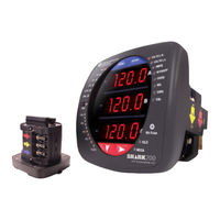
Electro Industries Shark 200 Installation & Operation Manual (353 pages)
Upgradeable Fully Featured Power & Energy Meter
Brand:
Electro Industries
| Category:
Measuring Instruments
| Size: 20.26 MB
Table of Contents
Electro Industries/Gaugetech Electro Industries/Gaugetech Doc # E149701
4
Customer Service and Support
5
Table of Contents
9
1 Three-Phase Power Measurement
13
Three-Phase System Configurations
13
Wye Connection
13
Three-Phase Wye Winding
14
Phasor Diagram Showing Three-Phase Voltages and Currents
14
Common Phase Voltages on Wye Services
15
Delta Connection
16
Three-Phase Delta Winding Relationship
16
Phasor Diagram, Three-Phase Voltages and Currents, Delta-Connected
17
Phasor Diagram Showing Three-Phase Four-Wire Delta-Connected System
17
Blondel's Theorem and Three Phase Measurement
18
Power, Energy and Demand
20
Power Use over Time
21
Power and Energy Relationship over Time
22
Energy Use and Demand
23
Reactive Energy and Power Factor
24
Voltage and Complex Current
24
Harmonic Distortion
26
Nondistorted Current Waveform
26
Distorted Current Waveform
27
Waveforms of the Harmonics
27
Power Quality
29
Typical Power Quality Problems and Sources
30
2 Meter Overview and Specifications
31
Voltage and Current Inputs
35
Universal Voltage Inputs
35
Current Inputs
35
Ordering Information
35
Key Technology
38
Obtaining a V-Switch Key
38
Enabling the V-Switch Key
39
Measured Values
40
Utility Peak Demand
41
Specifications
42
KYZ/RS485 Port Specifications
44
Infrared LED
45
Internal Schematic
45
Output Timing
45
Optional, through I/O Card Slots
47
Compliance
47
Accuracy
49
3 Mechanical Installation
51
Meter Front and Side Dimensions
51
200T Dimensions
52
Meter Back Dimensions
52
ANSI Installation Steps
53
ANSI and DIN Cutout Dimensions
53
DIN Installation Steps
54
Figure 3.5: ANSI Installation
54
DIN Installation
55
Transducer Installation
56
Specs for DIN Rail Mounting
56
DIN Rail (Slotted) Dimensions
56
Transducer on DIN Rail
56
DIN Rail Detail
57
4 Electrical Installation
59
Considerations When Installing Meters
59
CT Leads Terminated to Meter
62
CT Leads Terminated to Meter, #8 Screw for Lug Connection
62
CT Leads Pass through (no Meter Termination)
63
Pass through Wire Electrical Connection
63
Quick Connect Crimp-On Terminations
64
Quick Connect Electrical Connection
64
Voltage and Power Supply Connections
65
Ground Connections
65
Voltage Fuses
65
Meter Connections
65
Electrical Connection Diagrams
66
Example of Dual Phase Hookup
68
Example of Single Phase Hookup
69
Service: Delta, 3-Wire with no Pts, 2 Cts
73
Service: Delta, 3-Wire with 2 Pts, 2 Cts
74
Service: Delta, 3-Wire with 2 Pts, 3 Cts
75
Service: Current Only Measurement (Three Phase)
76
Service: Current Only Measurement (Dual Phase)
77
Service: Current Only Measurement (Single Phase)
78
Extended Surge Protection for Substation Instrumentation
79
Wiring Schematic for Extended Surge Suppression
79
5 Communication Installation
81
Irda Port
81
RS485 / KYZ Output (Com 2)
81
Shark 200 Meter Back with RS485 Communication Installation
82
Shark 200 Meter Connected to a PC Via RS485 Bus
82
2-Wire RS485 Connection
83
RS485 Daisy Chain Connection
84
Incorrect “T” and “Star” Topologies
84
Using the Unicom 2500
85
Unicom 2500 with Connections
85
Using the RS485 to USB Communication Converter
86
To Use the E205301
87
Meter Hookup
87
And Programming Overview
87
Accessing the Meter in Default Communication Mode
88
Protocol: Modbus RTU
88
Shark 200 Meter Device Profile Settings
93
CT, PT Ratios and System Hookup
93
Example CT Settings
95
Example PT Settings
95
Display Configuration
96
Phases Displayed
96
Auto Scroll Display
96
Enable on Face Plate of Display
96
Flip Power Factor Sign
97
Display Voltage in Secondary
97
Load Bar Custom Configuration
100
Enable Fixed Scale for Voltage Display
100
Energy, Power Scaling, and Averaging
101
Power Settings
101
Energy Settings
101
System Settings
102
Interval Window
102
Change the Password
103
Change the Meter Identification
103
Limits
104
To Set up a Limit
104
To Configure a Limit
105
Primary Fields
105
Time Settings
106
Using the Shark 200 Meter
109
Understanding Meter Face Elements
109
Face Plate with Elements
109
6 : Using the Shark® 200 Meter
110
Understanding Meter Face Buttons
110
Faceplate with Buttons
110
Using the Front Panel
111
Understanding Startup and Default Displays
111
Display Showing Watt-Hour Reading
112
Using the Main Menu
112
Using Reset Mode
113
Entering a Password
114
Using Configuration Mode
115
To Access Configuration Mode
115
Configuring the Scroll Feature
117
To Enable or Disable Auto-Scrolling
117
Configuring CT Setting
118
Configuring PT Setting
119
To Change the Value for the PT Numerator or Denominator
119
To Change the Value for the PT Scaling
119
Configuring Connection Setting
121
Configuring Communication Port Setting
121
To Enter the Address
122
To Select the Baud Rate
122
To Select the Protocol
122
Using Operating Mode
123
Possible Readings
123
Understanding the % of Load Bar
124
Performing Watt Hour Accuracy Testing (Verification)
125
Watt Hour Test Pulse
125
Using the Watt Hour Test Pulse
126
Test Procedure
127
Using the I/O Option Cards
129
Shark 200 Meter Back, Showing Option Card Slots and I/O Card
129
Detail of Guide Track
130
7 Using the I/O Option Cards
130
Configuring Option Cards
132
1Ma Output Card
132
Default Configuration
133
Wiring Diagram
134
Channel 0 - 1 Ma Output Card
134
20Ma Output Card (20Maos)
135
Default Configuration
136
Wiring Diagram
137
Digital Output (Relay Contact) / Digital Input Card (RO1S)
138
Relay Contact (2) / Status Input (2) Card
140
Wiring Diagram
140
Pulse Output (Solid State Relay Contacts Digital Input Card (P01S)
141
Default Configuration
142
Pulse Output (4) / Status Input (4) Card
143
Wiring Diagram
143
Fiber Optic Communication Card (FOSTS; FOVPS)
144
ST Type Connector
145
Versatile Link Type Connector
145
Wiring Diagram
145
10/100Baset Ethernet Communication Card (INP100S)
146
Default Configuration
147
IEC 61850 Protocol Ethernet Network Card (INP300S)
148
IEC61850 Protocol Ethernet Network Card
149
Default Configuration
149
8 : Using the Ethernet Card (INP100S)
151
Using the Ethernet Card (INP100S)
151
Hardware Connection
151
Meter with INP100S Card
151
Overview
151
Performing Network Configuration
152
INP100S Ethernet Card Features
152
Ethernet Communication
153
Embedded Web Server
153
Upgrading the Ethernet Card’s Firmware
161
Resetting the Ethernet Card
163
Email Notification
164
Data Push
170
NTP Time Server Synchronization
174
Modbus and DNP over Ethernet
174
8 Keep-Alive Feature
174
9 : Data Logging
177
Data Logging
177
Available Logs
177
Historical Logs
177
Limit/Alarm Log
177
System Events Log
178
Waveform Log
178
A: Shark® 200 Meter Navigation Maps
179
Main Menu Screens (Sheet 1)
180
Operating Mode Screens
181
Reset Mode Screens
182
Configuration Mode Screens
183
Modbus Register Map Sections
185
Data Formats
185
Ascii
185
B: Modbus Map and Retrieving Logs
185
B.4: Floating Point Values
186
B.5: Retrieving Logs Using the Shark® 200 Meter's Modbus Map
187
200 Meter Logs
188
B.5.1: Data Formats
188
I/O Change Log Tables
189
Card Change Flags
189
Card Current States
190
PQ Event Log
190
Historical Log Programmable Settings
190
B.5.3: Block Definitions
190
Historical Log Blocks
191
Header
191
Register List
192
Item Descriptor List
193
Log Status Block
194
Max Records
195
Records Used
195
Record Size
195
Log Availability
195
Log Retrieval Block
196
Log Retrieval Header
197
Records Per Window
198
Number of Repeats
199
Log Retrieval Window Block
199
Window Status
199
Record Number
200
Auto-Increment
200
B.5.4: Log Retrieval
200
Modbus Function Code 0X23
201
B.5.4.3: Log Retrieval Procedure
202
B.5.4.4: Log Retrieval Example
205
Timestamp
209
System Event Record
214
B.5.5: Log Record Interpretation
214
Alarm Record
218
Direction
218
Limit ID
218
Limit Type
218
Above Hysteresis
219
Above Setpoint
219
Identifier
219
Interpretation of Alarm Data
219
Below Hysteresis
220
Below Setpoint
220
Historical Log Record
221
I/O Change Log Record
222
PQ Event Record
223
Present States
223
Waveform Log Record
223
Log Retrieval Section
224
B.5.6: Examples
224
Historical Log 1 Record and Programmable Settings
226
Sample Historical Log 1 Record
226
Waveform Log Retrieval
227
Header Block Definition - 36 Bytes
228
Channel Sample Block Definition (4098 Bytes)
229
Parsing a Waveform Capture
229
Additional Waveform Processing
236
Event Channels
243
Parsing a PQ Event Record
243
PQ Event Record Binary Content Mapping
243
Timestamp (6B)
243
Event_Cycle_Tag = 0
245
Flags= 0
245
Present State/Event Channel Definition (2 Bytes)
246
Decimal Representation
249
B.6.1: Hex Representation
249
Modbus Register Map (MM-1 to MM-40)
250
Meter Data Section (Note 2)
252
Physical Layer
295
C: DNP Mapping
295
C.1: Supported Link Functions
296
Application Layer
296
C.3: Data Link Layer
296
Error Reply
298
Object Specifics
298
Object 1 - Binary Input Status with Flag
298
Object 10 - Binary Output States
298
C.4: Application Layer
298
Object 30 - Analog Inputs
299
Object 50 - Date and Time
299
Object 60 - Class Objects
299
DNP Object Point Map
300
Binary Input Status with Flags
300
Supported Flags
300
Binary Output States
301
Control Relay Outputs
302
Object 20 - Binary Counters (Primary Readings)
303
Object 30 - Analog Inputs (Secondary Readings)
304
Object 30 - Analog Inputs (Primary Readings)
307
Object 80 - Internal Indicator
309
DNP Message Layouts
309
Legend
309
Link Layer Related Frames
310
Application Layer Related Frames
310
Clear Restart
310
Reset Link
310
Reset Energy
311
Switch to Modbus
311
Reset Demand (Maximums & Minimums)
311
Internal Indication Bits
312
Bad Function
312
Object Unknown
312
Out of Range
312
Installation Procedures
313
D: Using the USB to Irda Adapter (CAB6490)
313
Using the IEC 61850 Protocol Ethernet Network Card (INP300S)
321
E.1: Overview of IEC 61850
321
E.1.1: Relationship of Clients and Servers in IEC 61850
322
Object Model Display on a Diagnostic Browser
323
E.1.2: Structure of IEC 61850 Network
324
Ssd
325
ICD - IED Capability Description
325
SCD - System Configuration Description
325
CID - Configured IED Description
325
E.1.2.1: Elements of an IEC 61850 Network
325
E.1.3: Steps in Configuring an IEC 61850 Network
327
E.2: Configuration Process
328
Electro Industries’ Implementation of the IEC 61850 Server
329
E.1.4.1: Shark® 200 Server Configuration
331
Free Tools for IEC 61850 Start-Up
332
E.1.5: Reference Materials
332
Commercial Tools for IEC 61850 Implementation
333
E.2: Using the Shark® 200 Meter's IEC 61850 Protocol Ethernet Network Card
333
E.2.2: Installing the IEC 61850 Protocol Ethernet Network Card
335
Network Time Protocol (NTP) Server
339
E.2.3.2: Configuring the Meter on the IEC 61850 Network
341
E.3: Viewing the IEC 61850 Protocol Ethernet Network Card's System Log
346
E.4: Upgrading the IEC 61850 Protocol Ethernet Network Card's Firmware
347
E.5: Resetting the IEC 61850 Protocol Ethernet Network Card
348
Keep-Alive Feature
349
Testing
349
Error Codes
350
Advertisement
Electro Industries Shark 200 Installation & Operation Manual (179 pages)
LOW-COST HIGH PERFORMANCE MULTIFUNCTION ELECTRICITY METER
Brand:
Electro Industries
| Category:
Measuring Instruments
| Size: 4.28 MB
Table of Contents
Customer Service and Support
4
Limitation of Warranty
4
Product Warranty
4
Statement of Calibration
4
About Electro Industries/Gaugetech
5
Chapter 1 Three-Phase Power Measurement
11
Three-Phase System Configurations
11
1: Wye Connection
11
2: Delta Connection
13
3: Blondell's Theorem and Three Phase Measurement
14
Power, Energy and Demand
16
Kilowatt-Hours
18
Reactive Energy and Power Factor
18
Harmonic Distortion
20
Power Quality
23
1: Voltage and Current Inputs
26
2: Ordering Information
27
Current Input
27
3: V-Switch ™ Key Technology
28
4: Measured Values
29
5: Utility Peak Demand
30
Specifications
30
Output Timing
31
Environmental Rating
32
Chapter 3 Mechanical Installation
35
ANSI Installation Steps
37
DIN Installation Steps
38
Chapter 4 Electrical Installation
41
Considerations When Installing Meters
41
CT Leads Terminated to Meter
42
CT Leads Pass through (no Meter Termination)
43
Quick Connect Crimp-On Terminations
44
Voltage and Power Supply Connections
45
Ground Connections
45
Voltage Fuses
45
Electrical Connection Diagrams
46
Service: 2.5 Element WYE, 4-Wire with no Pts, 3 Cts
50
Service: 2.5 Element WYE, 4-Wire with 2 Pts, 3 Cts
52
Service: Delta, 3-Wire with no Pts, 2 Cts
53
Service: Delta, 3-Wire with 2 Pts, 2 Cts
54
Service: Delta, 3-Wire with 2 Pts, 3 Cts
55
Service: Current Only Measurement (Three Phase)
56
Service: Current Only Measurement (Dual Phase)
57
Service: Current Only Measurement (Single Phase)
58
Chapter 5 Communication Installation
59
1: Irda Port (Com 1)
59
2: RS485 / KYZ Output (Com 2)
60
For All RS485 Connections
61
1: Using the Unicom 2500
63
Meter Connection
64
Modbus RTU
64
Display Configuration
67
1: Understanding Meter Face Elements
71
2: Understanding Meter Face Buttons
71
Using the Front Panel
72
1: Understanding Startup and Default Displays
72
2: Using the Main Menu
73
3: Using Reset Mode
73
4: Entering a Password
74
Configuration Mode
74
5: Using Configuration Mode
75
1: Configuring the Scroll Feature
76
2: Configuring CT Setting
77
3: Configuring PT Setting
78
4: Configuring Connection Setting
79
5: Configuring Communication Port Setting
79
Understanding the % of Load Bar
81
Performing Watt-Hour Accuracy Testing (Verification)
82
Installing Option Cards
84
Configuring Option Cards
84
3: Wiring Diagram
86
20Ma Output Card (20Maos)
87
Digital Output (Relay Contact) / Digital Input Card (RO1S)
89
2: Wiring Diagram
90
Pulse Output (Solid State Relay Contacts) / Digital Input Card (P01S)
91
Fiber Optic Communication Card (FOSTS; FOVPS)
93
Multi Mode
93
2: Default Configuration
95
Hardware Connection
97
Performing Network Configuration
98
Upgrading the Ethernet Card's Firmware
98
B.4: Floating Point Values
108
B.5.1: Data Formats
109
Block Size
111
Register List
112
B.5.4: Log Retrieval
117
B.5.4.2: Modbus Function Code 0X23
117
B.5.4.3: Log Retrieval Procedure
118
B.5.4.4: Log Retrieval Example
119
Alarm Record
126
C.2: Physical Layer
163
C.3: Data Link Layer
163
C.4: Application Layer
164
C.5: Error Reply
164
C.6: DNP Lite Register Map
165
C.7: DNP Message Layouts
167
D.2: Installation Procedures
171
Advertisement
Related Products
Electro Industries Shark 100
Electro Industries SM1-16
Electro Industries 1252
Electro Industries 250
Electro Industries Nexus 1250
Electro Industries Nexus 1252
Electro Industries Nexus 1262
Electro Industries Nexus 1271
Electro Industries Shark 100S
Electro Industries Shark 100T
Electro Industries Categories
Boiler
Measuring Instruments
Heater
Heating System
Fan
More Electro Industries Manuals
Login
Sign In
OR
Sign in with Facebook
Sign in with Google
Upload manual
Upload from disk
Upload from URL