Table of Contents
Advertisement
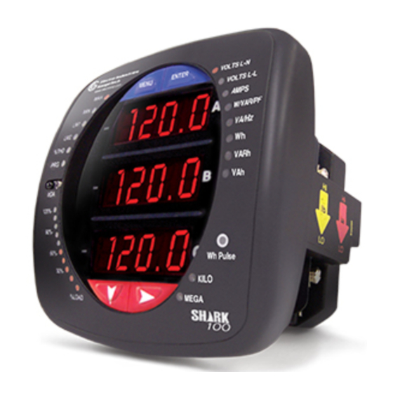
Shar k®100 & 100T
Low Cost, High Performance Multifunction Electricity Meter
Installation & Operation Manual
Revision 1.12
May 15, 2008
Doc #: E145701 V1.12
e
Electro Industries/GaugeTech
1800 Shames Drive
Westbury, New York 11590
Tel: 516-334-0870
Fax: 516-338-4741
Sales@electroind.com
www.electroind.com
"The Leader in Web Accessed Power Monitoring and Control"
Advertisement
Table of Contents

Related Manuals for Electro Industries Shark 100


Summary of Contents for Electro Industries Shark 100
- Page 1 Shar k®100 & 100T Low Cost, High Performance Multifunction Electricity Meter Installation & Operation Manual Revision 1.12 May 15, 2008 Doc #: E145701 V1.12 Electro Industries/GaugeTech 1800 Shames Drive Westbury, New York 11590 Tel: 516-334-0870 Fax: 516-338-4741 Sales@electroind.com www.electroind.com “The Leader in Web Accessed Power Monitoring and Control”...
- Page 2 Electro Industries/GaugeTech Doc # E145701...
- Page 3 Electro Industries/GaugeTech. © 2008 Shark® is a registered trademark of Electro Industries/Gauge Tech. Printed in the United States of America. Electro Industries/GaugeTech Doc # E145701...
- Page 4 516-334-0870 or fax 516-338-4741. Product Warranty Electro Industries/GaugeTech warrants all products to be free from defects in material and workmanship for a period of four years from the date of shipment. During the warranty period, we will, at our option, either repair or replace any product that proves to be defective.
- Page 5 About Electro Industries/GaugeTech Founded in 1973 by engineer and inventor Dr. Samuel Kagan, Electro Industries/GaugeTech changed the face of power monitoring forever with its first breakthrough innovation: an affordable, easy-to-use AC power meter. Thirty years later, Electro Industries/GaugeTech, the leader in Web-Accessed Power Monitoring, continues to revolutionize the industry with the highest quality, cutting edge power monitoring and control technology on the market today.
- Page 6 Electro Industries/GaugeTech Doc # E145701...
-
Page 7: Table Of Contents
......5-6 5.2: Shark® 100T Transducer Communication and Programming Overview ..5-7 Electro Industries/GaugeTech Doc # E145701... - Page 8 B.4: Floating Point Values ......B-2 B.5: Modbus Register Map (MM-1 to MM-8) ....B-2 Electro Industries/GaugeTech Doc # E145701...
- Page 9 E.1: Introduction ....... E-1 E.2: Installation Procedures ......E-1 Electro Industries/GaugeTech Doc # E145701...
- Page 10 Electro Industries/GaugeTech viii Doc # E145701...
-
Page 11: Three-Phase System Configurations
The three voltages are separated by 120 o electrically. Under balanced load conditions with unity power factor the currents are also separated by 120 o . However, unbalanced loads and other conditions can cause the currents to depart from the ideal 120 o separation. Electro Industries/GaugeTech Doc # E145701... - Page 12 Table 1.1, even though a neutral or ground wire is not physically present at the load. The transformer is the best place to determine the circuit connection type because this is a location where the voltage reference to ground can be conclusively identified. Electro Industries/GaugeTech Doc # E145701...
-
Page 13: 2: Delta Connection
On a 120/240 volt, four-wire, grounded delta service the phase-to-ground voltage would be 120 volts on two phases and 208 volts on the third phase. Figure 1.5 shows the phasor diagram for the voltages in a three-phase, four-wire delta system. Electro Industries/GaugeTech Doc # E145701... -
Page 14: 3: Blondell's Theorem And Three Phase Measurement
In modern digital meters, Blondell's Theorem is still applied to obtain proper metering. The difference in modern meters is that the digital meter measures each phase voltage and current and calculates the single-phase power for each phase. The meter then sums the three phase powers to a Electro Industries/GaugeTech Doc # E145701... - Page 15 In the circuit of Figure 1.6 we must measure the power flow in three wires. This will require three voltage coils and three current coils (a three element meter). Similar figures and conclusions could be reached for other circuit configurations involving delta-connected loads. Electro Industries/GaugeTech Doc # E145701...
-
Page 16: Power, Energy And Demand
1/60 (converting the time base from minutes to hours). Kilowatts Time (minutes) Figure 1.7: Power use over time Electro Industries/GaugeTech Doc # E145701... - Page 17 59.68 kWh. The same process is applied to calculate the 15-minute demand value. The demand value associated with the example load is 59.68 kWh/hr or 59.68 kWd. Note that the peak instantaneous value of power is 80 kW, significantly more than the demand value. Electro Industries/GaugeTech Doc # E145701...
-
Page 18: Reactive Energy And Power Factor
(angularly rotated 90 or perpendicular) to the voltage. Figure 1.9 shows a single-phase voltage and current and breaks the current into its in-phase and quadrature components. Electro Industries/GaugeTech Doc # E145701... - Page 19 A second type of power factor is Displacement Power Factor. Displacement PF is based on the angular relationship between the voltage and current. Displacement power factor does not consider the magnitudes of voltage, current or power. It is solely based on the phase angle differences. As a Electro Industries/GaugeTech Doc # E145701...
-
Page 20: Harmonic Distortion
Figure 1.11 shows a current waveform with a slight amount of harmonic distortion. The waveform is still periodic and is fluctuating at the normal 60 Hz frequency. However, the waveform is not a smooth sinusoidal form as seen in Figure 1.10. Electro Industries/GaugeTech 1-10 Doc # E145701... - Page 21 When harmonics are present it is important to remember that these quantities are operating at higher frequencies. Therefore, they do not always respond in the same manner as 60 Hz values. Electro Industries/GaugeTech 1-11 Doc # E145701...
- Page 22 Waveform capture is a real-time data collection event. Waveform capture should not be confused with waveform recording that is used to record multiple cycles of all voltage and current waveforms in response to a transient condition. Electro Industries/GaugeTech 1-12 Doc # E145701...
-
Page 23: Power Quality
If a power quality problem is suspected, it is generally wise to consult a power quality professional for assistance in defining the cause and possible solutions to the problem. Electro Industries/GaugeTech 1-13 Doc # E145701... - Page 24 Electro Industries/GaugeTech 1-14 Doc # E145701...
-
Page 25: Chapter 2: Shark® Meter Overview And Specifications
RS-485 communication via Modbus RTU, Modbus ASCII and DNP 3.0 (V3 and V4) protocols. The Figure 2.2: Shark® 100T unit is designed to install using DIN Rail Mounting (Transducer Only) (see section 3.4). Electro Industries/GaugeTech Doc #: E145701... -
Page 26: 1: Voltage And Current Inputs
2.1.2: Model Number plus Option Numbers Model Frequency Current V-Switch Power Mounting Class Pack Supply (Shark 100 Only) (Shark 100 Only) Shark® 100 - 50 - 10 - V1 Meter/ 50 Hz 5 Amp Default V-Switch 90-265V... -
Page 27: V-Switch® Technology
Shark® 100 Meter Measured Values Measured Values Real Time Voltage L-N Voltage L-L Current Per Phase Current Neutral Watts +Watt-Hr - Watt-Hr Watt-Hr Net +VAR-Hr -VAR-Hr VAR-Hr Net VA-Hr Frequency %THD Voltage Angles Current Angles % of Load Bar Electro Industries/GaugeTech Doc #: E145701... -
Page 28: 5: Utility Peak Demand
O or U Lug Electrical Connection (Diagram 4.1) Pass-through Wire, 0.177" / 4.5mm Maximum Diameter (Diagram 4.2) Quick Connect, 0.25" Male Tab (Diagram 4.3) • Fault Withstand: 100A/10sec., 300A/3sec., 500A/1sec. • Reading: Programmable Full Scale to any CT Ratio Electro Industries/GaugeTech Doc #: E145701... - Page 29 Dimensions: (H4.85 x W4.82 x L4.25) inches, (H123.2 x W123.2 x L105.4) mm Mounts in 92mm square DIN or ANSI C39.1, 4" Round Cut-out • Weight: 2 pounds, 0.907kg (ships in a 6"/152.4mm cube container) Electro Industries/GaugeTech Doc #: E145701...
-
Page 30: Compliance
1 - 120% 10 Segment Resolution Scalable * Accuracy stated for 5 amp secondary WYE or Delta connections. For 1 amp secondary or 2.5 element connections, add 0.1% of Full Scale + 1 digit to accuracy specification. Electro Industries/GaugeTech Doc #: E145701... -
Page 31: Chapter 3: Mechanical Installation
Mechanical Installation 3.1: Introduction The Shark 100 meter can be installed using a standard ANSI C39.1 (4" Round) or an IEC 92mm DIN (Square) form. In new installations, simply use existing DIN or ANSI punches. For existing panels, pull out old analog meters and replace with the Shark 100. The various models use the same installation. -
Page 32: Ansi Installation Steps
2. Slide ANSI 12 Mounting Gasket onto back of meter with rods in place. 3. Slide meter with Mounting Gasket into panel. 4. Secure from back of panel with lock washer and nut on each threaded rod. Use a small wrench to tighten. Do not overtighten. Electro Industries/GaugeTech Doc #: E145701... -
Page 33: Din Installation Steps
3.3: DIN Installation Steps DIN Mounting Bracket Top Mounting Bracket Groove Bottom Mounting Bracket Groove #8 Screw Shark 100 Meter with NEMA 12 Mounting Gasket Remove (unscrew) ANSI Studs for DIN Installation Figure 3.8: DIN Mounting Procedure DIN INSTALLATION STEPS: 1. -
Page 34: Shark 100T Transducer Installation
PLCs. DIN Rails are made of cold rolled steel electrolitically plated and are also available in aluminum, PVC, stainless steel Figure 3.10: DIN Rail Detail and copper. Electro Industries/GaugeTech Doc # E145701... -
Page 35: Chapter 4: Electrical Installation
Appropriate safety gloves, safety glasses and protective clothing is recommended. During normal operation of the Shark 100 Meter, dangerous voltages flow through many parts of the meter, including: Terminals and any connected CTs (Current Transformers) and PTs (Potential Transformers), all I/O Modules (Inputs and Outputs) and their circuits. -
Page 36: Ct Leads Terminated To Meter
4.2: CT Leads Terminated to Meter The Shark 100 is designed to have Current Inputs wired in one of three ways. Diagram 4.1 shows the most typical connection where CT Leads are terminated to the meter at the Current Gills. This connection uses Nickel-Plated Brass Studs (Current Gills) with screws at each end. -
Page 37: Ct Leads Pass Through (No Meter Termination)
In this case, remove the Current Gills and place the CT wire directly through the CT opening. The opening will accomodate up to 0.177” / 4.5mm maximum diameter CT wire. CT Wire passing through meter Current Gills removed Figure 4.2: Pass-Through Wire Electrical Connection Electro Industries/GaugeTech Doc #: E145701... -
Page 38: Quick Connect Crimp Ct Terminations
4.4: Quick Connect Crimp CT Terminations For Quick Termination or for Portable Applications, a Quick Connect Crimp CT Connection can also be used. Crimp CT Terminations Figure 4.3: Quick Connect Electrical Connection Electro Industries/GaugeTech Doc #: E145701... -
Page 39: Voltage And Power Supply Connections
EIG recommends the use of fuses on each of the sense voltages and on the control power, even though the wiring diagrams in this chapter do not show them. Use a 0.1 Amp fuse on each voltage input. Use a 3 Amp fuse on the power supply. Electro Industries/GaugeTech Doc # E145701... -
Page 40: Electrical Connection Diagrams
Current Only Measurement (Three Phase) Current Only Measurement (Dual Phase) Current Only Measurement (Single Phase) 1. Service: WYE, 4-Wire with No PTs, 3 CTs Select: “3 EL WYE” (3 Element Wye) in Meter Programming setup. Electro Industries/GaugeTech Doc # E145701... - Page 41 2. Service: 2.5 Element WYE, 4-Wire with No PTs, 3 CTs Select: “2.5 EL WYE” (2.5 Element Wye) in Meter Programming setup. Electro Industries/GaugeTech Doc #: E145701...
- Page 42 3. Service: WYE, 4-Wire with 3 PTs, 3 CTs Select: “3 EL WYE” (3 Element Wye) in Meter Programming setup. Electro Industries/GaugeTech Doc # E145701...
- Page 43 4. Service: 2.5 Element WYE, 4-Wire with 2 PTs, 3 CTs Select: “2.5 EL WYE” (2.5 Element Wye) in Meter Programming setup. Electro Industries/GaugeTech Doc #: E145701...
- Page 44 5. Service: Delta, 3-Wire with No PTs, 2 CTs Select: “2 Ct dEL” (2 CT Delta) in Meter Programming setup. Electro Industries/GaugeTech 4-10 Doc # E145701...
- Page 45 6. Service: Delta, 3-Wire with 2 PTs, 2 CTs Select: “2 Ct dEL” (2 CT Delta) in Meter Programming setup. Electro Industries/GaugeTech 4-11 Doc # E145701...
- Page 46 7. Service: Delta, 3-Wire with 2 PTs, 3 CTs Select: “2 Ct dEL” (2 CT Delta) in Meter Programming setup. NOTE: The third CT for hookup is optional and is for Current Measurement only. Electro Industries/GaugeTech 4-12 Doc #: E145701...
- Page 47 * Even if the meter is used for only amp readings, the unit requires a Voltage reference. Please make sure that the voltage input is attached to the meter. AC Control Power can be used to provide the Reference Signal. Electro Industries/GaugeTech 4-13 Doc # E145701...
- Page 48 * Even if the meter is used for only amp readings, the unit requires a Voltage reference. Please make sure that the voltage input is attached to the meter. AC Control Power can be used to provide the Reference Signal. Electro Industries/GaugeTech 4-14 Doc #: E145701...
- Page 49 * Even if the meter is used for only amp readings, the unit requires a Voltage reference. Please make sure that the voltage input is attached to the meter. AC Control Power can be used to provide the Reference Signal. Electro Industries/GaugeTech 4-15 Doc #: E145701...
- Page 50 Electro Industries/GaugeTech 4-16 Doc #: E145701...
-
Page 51: Chapter 5: Communication Installation
5.1.1: IrDA Port (Com 1) The Shark 100 meter’s Com 1 IrDA Port is on the face of the meter. The IrDA Port allows the unit to be set up and programmed using a PDA or remote laptop without the need for a communication cable. - Page 52 Care should be taken to connect + to + and - to - connections. Figure 5.2: RS-485 Communication Installation The Shark 100 meter’s RS-485 can be programmed with the buttons on the face of the meter or by using Communicator EXT 3.0 software.
- Page 53 Figure 5.4: Shark 100 Connected to PC via RS485 As shown in Figure 5.4, to connect a Shark 100 to a PC, you need to use an RS485 to RS232 converter, such as EIG’s Unicom 2500. See Section 5.1.3.1 for information on using the Unicom 2500 with the Shark 100.
- Page 54 When they are used, the value of the Termination Resistors is determined by the electrical parameters of the cable. Figure 5.6 shows a representation of an RS485 Daisy Chain connection. Refer to Section 5.1.2.1 for details on RS485 connection for the Unicom 2500. Figure 5.6: RS485 Daisy Chain Connection Electro Industries/GaugeTech Doc #: E145701...
- Page 55 Figure 5.7: Incorrect “T” and “Star” Topologies Electro Industries/GaugeTech Doc #: E145701...
- Page 56 5 5 . . 1 1 . . 3 3 . . 1 1 : : U U s s i i n n g g t t h h e e U U n n i i c c o o m m 2 2 5 5 0 0 0 0 The Unicom 2500 provides RS485/RS232 conversion. In doing so it allows a Shark 100 with the RS485 option to communicate with a PC.
-
Page 57: 1: Factory Initial Default Settings
NOTE If you do not connect with the Factory Initial Default Settings within 5 seconds after powering on the meter, the Device Profile reverts to the programmed Device Profile. In that case, disconnect and reconnect power before clicking the Connect button. Electro Industries/GaugeTech Doc #: E145701... - Page 58 6. When changes are complete, click the Update button to send a new profile to the meter. 7. Click Cancel to Exit the Profile (or) 8. Click other tabs to update other aspects of the Profile (see section 5.2.2 below). Electro Industries/GaugeTech Doc #: E145701...
- Page 59 Pt-n value is 3470, Pt-d value is 115, Pt-Multiplier value is 100 345,000/69 Volts: Pt-n value is 345, Pt-d value is 69, Pt-Multiplier value is 1000. NOTE: Settings are the same for Wye and Delta configurations. Electro Industries/GaugeTech Doc #: E145701...
- Page 60 NOTE: If incorrect values are entered on this screen the following message appears: WARNING: Current, CT, PT and Energy Settings will cause invalid energy accumulator values. Change the inputted settings until the message disappears. Electro Industries/GaugeTech 5-10 Doc #: E145701...
- Page 61 NO DEFAULT PASSWORD) Enable Password for Reset Enable Password for Configuration Change Password Change VSwitch (Call Electro Industries for Update Information) Change Device Designation Limits (VSwitch 4 Only) For up to 8 Limits, Set: Address: Modbus Address (1 based)
- Page 62 Electro Industries/GaugeTech 5-12 Doc #: E145701...
-
Page 63: Chapter 6: Using The Meter
Using the Meter 6.1: Introduction The Shark 100 meter can be configured and a variety of functions can be accomplished simply by using the Elements and the Buttons on the meter face. This chapter will review Front Panel Navigation. Complete Navigation Maps can be found in Appendix A of this manual. -
Page 64: Of Load Bar
1 - 2 1 - 3 1 - 4 1 - 5 1 - 6 1 - 7 1 - 8 1 - 9 108% 1 - 10 120% All Blink >120% Electro Industries/GaugeTech Doc #: E145701... -
Page 65: Watt-Hour Accuracy Testing (Verification)
Watt-Hour ensure that the unit’s energy measurements Test Pulse are correct. Since the Shark 100 is a traceable revenue meter, it contains a utility grade test pulse that can be used to gate an accuracy standard. This is an essential feature required of all billing Figure 6.3: Watt-Hour Test Pulse... -
Page 66: Upgrade The Meter Using V-Switches
To change the V-Switch®, follow these simple steps: 1. Install Communicator EXT 3.0 in your computer. 2. Set up Shark 100 to communicate with your computer (see Chapter 5); power up your meter. 3. Log on to Communicator EXT 3.0 software. -
Page 67: Overview
An example of a Wh reading is shown here. The Shark 100 will continue to scroll through the Parameter Designators, providing readings until one of the buttons on the front panel is pushed, causing the meter to enter one of the other MODES. -
Page 68: Configuration
If you push the RIGHT button, the RESET All? YES screen appears. To Reset All, you must enter a 4-digit Password, if Enabled in the software (see section 5.22). Push ENTER; the following Password screen appears. Electro Industries/GaugeTech Doc #: E145701... -
Page 69: 1: Enter Password (Only If Enabled In Software)
Program (PRG) LED flashes on the left side of the meter face.) If an incorrect Password has been entered, “PASS ---- FAIL” appears and the screen returns to Reset ALL? YES. Electro Industries/GaugeTech Doc #: E145701... -
Page 70: 3: Configuration Mode
If that is the case, it will only scroll the selected display. Additionally, the meter will only scroll the display enabled by the V-Switch that is installed. Push ENTER (YES or no) and the screen scrolls to the Ct Parameters. Electro Industries/GaugeTech Doc # E145701... -
Page 71: 2: Program Configuration Mode Screens
The STORE ALL screen appears. 5. Use the RIGHT Button to scroll from YES to no. 6. While in STORE ALL YES, push ENTER to change the setting. Store All Done appears. Then, the meter RESETS. Electro Industries/GaugeTech Doc #: E145701... -
Page 72: 3: Configure Ct Setting
Push DOWN or RIGHT and the Password screen appears (see section 7.3.2.1). Push MENU and you will return to the MAIN MENU. NOTE: Ct-n and Ct-S are dictated by Primary Voltage. Ct-d is Secondary Voltage. Electro Industries/GaugeTech Doc # E145701... -
Page 73: 4: Configure Pt Setting
Push DOWN or RIGHT and the Password screen appears (see section 7.3.2.1). Push MENU and you will return to the MAIN MENU. NOTE: Pt-n and Pt-S are dictated by Primary Voltage. Pt-d is Secondary Voltage. Electro Industries/GaugeTech Doc # E145701... -
Page 74: 5: Configure Connection (Cnct) Setting
2.5 Element Wye Push ENTER and the screen scrolls through the other CFG parameters. Push DOWN or RIGHT and the Password screen appears (see section 7.3.2.1). Push MENU and you will return to the MAIN MENU. Electro Industries/GaugeTech Doc # E145701... -
Page 75: 6: Configure Communication Port Setting
Modbus ASCII Protocol Push ENTER and the screen scrolls through the other CFG parameters. Push DOWN or RIGHT and the Password screen appears (see section 7.3.2.1). Push MENU and you will return to the MAIN MENU. Electro Industries/GaugeTech Doc # E145701... - Page 76 7.3.4: Operating Mode Operating Mode is the Shark 100 meter’s Default Mode. After Start Up, the meter automatically scrolls through these parameter screens, if scrolling is enabled. The screen changes every 7 seconds. Scrolling is suspended for 3 minutes after any button is pressed.
-
Page 77: Operating Mode
Shark Navigation Maps A.1: Introduction The Shark 100 meter can be configured and a variety of functions performed using the BUTTONS on the meter face. An Overview of the Elements and Buttons on the meter face can be found in Chapter 6. - Page 78 Electro Industries/GaugeTech Doc #: E145701...
- Page 79 Electro Industries/GaugeTech Doc #: E145701...
- Page 80 Electro Industries/GaugeTech Doc # E145701...
- Page 81 Electro Industries/GaugeTech Doc # E145701...
- Page 82 Electro Industries/GaugeTech Doc # E145701...
-
Page 83: Appendix B: Modbus Mapping For Shark® Meter
The Modbus Map for the Shark 100 Meter gives details and information about the possible readings of the meter and about the programming of the meter. The Shark 100 can be programmed using the buttons on the face plate of the meter (Chapter 7). The meter can also be programmed using software. -
Page 84: B.4: Floating Point Values
Exponent = the whole number before the decimal point. Mantissa = the positive fraction after the decimal point. B.5: Modbus Register Map (MM-1 1 to MM-8 8 ) The Shark 100 Modbus Register Map begins on the following page. Electro Industries/GaugeTech Doc # E145701... - Page 85 -1.00 to +1.00 none 0401 - 0402 1026 - 1027 Frequency FLOAT 0 to 65.00 0403 - 0404 1028 - 1029 Neutral Current FLOAT 0 to 9999 M amps Block Size: read-only Primary Energy Block Electro Industries/GaugeTech Doc# E145701 MM-1...
- Page 86 0BD1 - 0BD2 3026 - 3027 VAs, 3-Ph, Minimum Avg Demand FLOAT -9999 M to +9999 M 0BD3 - 0BD4 3028 - 3029 Positive Power Factor, 3-Ph, Minimum Avg Demand FLOAT -1.00 to +1.00 none Electro Industries/GaugeTech Doc# E145701 MM-2...
- Page 87 0FAD - 0FAD 4014 - 4014 Phase A Voltage 0th harmonic magnitude UINT16 0 to 65535 none 0FAE - 0FAE 4015 - 4015 Phase A Voltage 1st harmonic magnitude UINT16 0 to 65535 none Electro Industries/GaugeTech Doc# E145701 MM-3...
- Page 88 55F0 - 55F0 22001 - 22001 Terminate Programmable Settings Update UINT16 any value meter leaves PS update mode via reset 55F1 - 55F1 22002 - 22002 Calculate Programmable Settings Checksum UINT16 meter calculates checksum on RAM copy of PS block Electro Industries/GaugeTech Doc# E145701 MM-4...
- Page 89 = power scale (0-unit, 3-kilo, 6-mega, 8-auto) nn = number of energy digits (5-8 --> 0-3) eee = energy scale (0-unit, 3-kilo, 6-mega) ddd = energy digits after decimal point (0-6) See note 10. Electro Industries/GaugeTech Doc# E145701 MM-5...
- Page 90 755A - 755E 30043 - 30047 Limit #4 SINT16 755F - 7563 30048 - 30052 Limit #5 SINT16 same as Limit #1 same as Limit #1 same as Limit #1 7564 - 7568 30053 - 30057 Limit #6 SINT16 Electro Industries/GaugeTech Doc# E145701 MM-6...
- Page 91 0 to 4095 amps see Amps A/B/C above 9C60 - 9CA2 40033 - 40099 Reserved none 9CA3 - 9CA3 40100 - 40100 Reset Energy Accumulators UINT16 write-only register; always reads as 0 password Block Size: Electro Industries/GaugeTech Doc# E145701 MM-7...
- Page 92 M denotes a 1,000,000 multiplier. Not applicable to Shark 100, V-Switch 1, 2, or 3 Writing this register causes data to be saved permanently in EEPROM. If there is an error while saving, a slave device failure exception is returned and programmable settings mode automatically terminates via reset.
-
Page 93: C.1: Introduction
Appendix C DNP Mapping for Shark C.1: Introduction The DNP Map for the Shark 100 Meter shows the client-server relationship in the Shark’s use of DNP Protocol. C.2: DNP Mapping (DNP-1 1 to DNP-2 2 ) The Shark 100 DNP Point Map follows. - Page 94 Electro Industries/GaugeTech Doc #: E145701...
- Page 95 5 Amps A SINT16 0 to 32767 (10 / 32768) Values above 10A secondary read 32767. 5 Amps B SINT16 0 to 32767 (10 / 32768) 5 Amps C SINT16 0 to 32767 (10 / 32768) Electro Industries/GaugeTech DNP-1 Doc # E145701...
- Page 96 0 to 32767 (10 / 32768) For 1A model, multiplier is (2 / 32768) and values above 2A secondary read 32767. Internal Indication 1 Device Restart Bit none Clear via Function 2 (Write), Qualifier Code Electro Industries/GaugeTech DNP-2 Doc # E145701...
-
Page 97: D.2: Data Link Layer
D.1: DNP Implementation PHYSICAL LAYER The Shark 100 meter is capable of using RS-485 as the physical layer. This is accomplished by connecting a PC to the Shark with the RS-485 connection on the back face of the meter. RS-485 RS-485 provides multi-drop network communication capabilities. -
Page 98: D.3: Transport Layer
Read ( Function 1 ) Objects supporting the READ function are: • Binary Outputs ( Object 10 ) • Counters ( Object 20 ) • Analog Inputs ( Object 30 ) • Class ( Object 60 ) Electro Industries/GaugeTech Doc #: E145701... -
Page 99: D.4.1.1: Binary Output Status (Obj. 10, Var. 2
Binary Output Status supports the following functions: Read ( Function 1 ) A READ request for Variation 0 will be responded to with Variation 2. Binary Output Status is used to communicate the following data measured by Shark meters: Electro Industries/GaugeTech Doc #: E145701... -
Page 100: D.4.1.2: Control Relay Output (Obj. 12, Var. 1
Use of the DIRECT OPERATE ( Function 5 ) function will operate only with the settings of Pulsed ON ( Code = 1 of Control Code Field ) once ( Count = 0x01 ) for ON 1 millisecond and OFF 0 milliseconds. Electro Industries/GaugeTech Doc # E145701... -
Page 101: D.4.1.3: 32-Bit Binary Counter Without Flag (Obj. 20, Var. 5
Hour Readings Hour Readings (Points 0 - 4) Point Readings Unit +W Hour -W Hour +VAR Hour VARh -VAR Hour VARh +VA Hour * These readings may be cleared by using the Contol Relay Output Block. Electro Industries/GaugeTech Doc #: E145701... -
Page 102: D.4.1.4: 16-Bit Analog Input Without Flag (Obj. 30, Var. 4
Phase BN Voltage Phase CN Voltage These points are formatted as 2's complement fractions. They represent a fraction of a 150 V Secondary input. Inputs of above 150 V Secondary will be pinned at 150 V Secondary. Electro Industries/GaugeTech Doc # E145701... - Page 103 This point is formatted as a 2's complement fraction. It represents a fraction of 4500 W Secondary in normal operation, or 3000 W Secondary in Open Delta operation. Inputs above/below +/-4500 or +/-3000 W Secondary will be pinned at +/-4500 or +/-3000 W Secondary, respectively. Electro Industries/GaugeTech Doc # E145701...
- Page 104 These points are formatted as 2's complement fractions. They represent a fraction of 4500 W Secondary in normal operation, or 3000 W Secondary in Open Delta operation. Inputs above/below +/-4500 or +/-3000 W Secondary will be pinned at +/-4500 or +/-3000 W Secondary, respectively. Electro Industries/GaugeTech Doc # E145701...
- Page 105 Pt-n value is 1380, Pt-d value is 69, Pt-S value is 100. 115 Volts (Reads 347,000 Volts): Pt-n value is 3470, Pt-d value is 115, Pt-S value is 100. 69 Volts (Reads 347,000 Volts): Pt-n value is 347, Pt-d value is 69, Pt-S value is 1000. Electro Industries/GaugeTech Doc # E145701...
-
Page 106: D.4.1.5: Class 0 Data (Obj. 60, Var. 1
Internal Indications may be indexed by Qualifier Code 0. Device Restart ( Point 0 ) This bit is set whenever the meter has reset. The polling device may clear this bit by Writing ( Function 2 ) to Object 80, Point 0. Electro Industries/GaugeTech D-10 Doc # E145701... -
Page 107: Appendix E: Using The Usb To Irda Adapter
The Found New Hardware Wizard allows you to install the software for the Adapter. Click the Radio Button next to Install from a list or specific location. 4. Click Next. You will see the screen shown on the next page. E Electro Industries/Gauge Tech Doc# E145721... - Page 108 These selections allow the Adapter’s driver to be copied from the Installation disk to your 6. Click Next. You will see the screen shown below. 7. When the driver for the Adapter is found, you will see the screen shown on the next page. E Electro Industries/Gauge Tech Doc# E145721...
- Page 109 9. You will see the two windows shown below. Click Continue Anyway. 10. You will see the screen shown on the next page while the Adapter’s driver is being installed on your PC. E Electro Industries/Gauge Tech Doc# E145721...
- Page 110 13. Position the USB to IrDA Adapter so that it points directly at the IrDA on the front of the Shark 100 meter. It should be as close as possible to the meter, and not more than 15 inches/38 cm away from it. 14. The Found New Hardware Wizard screen opens again. E Electro Industries/Gauge Tech Doc# E145721...
- Page 111 15. Click Next. You will see the screen shown below. 16. Make sure the first Radio Button and the first Checkbox are selected, as shown in the above screen. Click Next. You will see the two screens shown on the next page. E Electro Industries/Gauge Tech Doc# E145721...
- Page 112 17. When the installation is complete, you will see the screen shown on the next page. E Electro Industries/Gauge Tech Doc# E145721...
- Page 113 IrDA, again. 19. Double-click on the Standard Modem over IR link (this is the USB to IrDA Adapter). You will see the Properties screen for the Adapter. E Electro Industries/Gauge Tech Doc# E145721...
- Page 114 20. Click the Modem tab. The Com Port that the Adapter is using is displayed in the screen. 21. Use this Com Port to connect to the meter from your PC, using the Communicator EXT software. Refer to Chapter 5 of the Communicator EXT 3.0 User’s Manual for detailed connection instructions. E Electro Industries/Gauge Tech Doc# E145721...
Need help?
Do you have a question about the Shark 100 and is the answer not in the manual?
Questions and answers