Sign In
Upload
Manuals
Brands
ProMinent Manuals
Controller
DULCOMETER
ProMinent DULCOMETER Manuals
Manuals and User Guides for ProMinent DULCOMETER. We have
7
ProMinent DULCOMETER manuals available for free PDF download: Assembly And Operating Instructions Manual, Installation And Configuration Manual
ProMinent DULCOMETER Assembly And Operating Instructions Manual (185 pages)
Multi-parameter Controller
Brand:
ProMinent
| Category:
Controller
| Size: 5.08 MB
Table of Contents
Section 1
3
Table of Contents
3
Operating Concept
7
Functions of the Keys
10
Changes the Set Operating Language
11
Acknowledge Fault or Warning Message
12
The Key Lock
13
Entries in the Display [Menu]
14
ID Code
15
A Complete Measuring Station May Comprise the Following
17
Safety and Responsibility
18
Explanation of the Safety Information
18
General Safety Notes
19
Intended Use
20
Users' Qualifications
21
Safety
21
Functional Description
23
Mounting and Installation
24
Wall Mounting
26
Mounting Mechanical
26
Scope of Supply
26
Control Panel Installation
28
Electrical Installation
31
Specification of the Threaded Connectors
32
Terminal Diagram
33
Cable Cross-Sections and Cable End Sleeves
39
Wall Mounting and Control Panel Installation
40
Switching of Inductive Loads
41
Connect the Sensors Electrically to the Controller
43
Commissioning
48
Switch-On Behaviour During Commissioning
48
Adjusting the Backlight and Contrast of the Controller Display
49
Resetting the Operating Language
49
Defining the Metering and Control Process
49
Configuration of Measured Variables
50
Information about the Measured Variables
51
Calibrating the Controller
58
Calibrating the Ph Measured Value
59
Selection of the Ph Calibration Process
63
2-Point Ph Sensor Calibration (CAL)
64
Ph Sensor Calibration (CAL) with an External Sample
67
Calibration of the Ph Sensor (CAL) by Data Input
70
Calibrating the ORP Measured Value
73
Selection of the Calibration Process for ORP
73
Single Point Calibration ORP Sensor (CAL)
73
ORP Sensor Data Calibration (CAL)
75
Calibrating Fluoride (F ) Measured Value [Ma]
77
Selection of the Calibration Process for Fluoride
77
2-Point Fluoride Sensor Calibration (CAL)
78
1-Point Fluoride Sensor Calibration (CAL)
80
Calibrating the Measured Value for Amperometric Measured Variables
82
Selection of the Calibration Process for Amperometric Measured Variables
82
Slope Calibration
83
Calibration of Zero Point
86
Calibrating the Measured Value for the Measured Variable DO
88
Selection of the Calibration Process for the Measured Variable O
89
Selection of the Calibration Process for the Measured Variable DO
90
Zero Point Calibration for the Measured Variable DO
92
DO Value Calibration for the Measured Variable DO
94
Measured Value [Ma General] Calibration
96
Setting the [Control]
97
Control Parameter [Type]
104
Control Parameter [System Response]
105
Control Parameter [Setpoint]
105
Control Parameter [Xp]
106
Control Parameter [Ti]
107
Control Parameter [Td]
107
Control Parameter [Add. Basic Load]
107
Control Parameter [Checkout Time]
107
Control Parameter [Max. Ctrl Var.]
107
Disturbance Variable
107
Remote Setpoint Via a 0/4
110
Parameter Switch] Via the Digital Input or [Timer]
112
Setting the [Limit Values]
116
Function of the Limit Values
116
Setting Limit Value Channel 1
118
Setting [Limit 1]
119
Setting [Limit 2]
119
Setting [System Response]
119
Setting the [Pumps]
120
Setting up [Pump 1]
120
Setting the [Relays]
123
Setting Relay 1
123
Function Description [Timer]
125
Function Description [Off]
125
Function Description [Control Variable]
125
Function Description [Limit 1] or [Limit 2]
125
Function Description [Control Variable]
126
Setting [Digital Inputs]
127
Setting [Digital Input 1]
127
Setting the [Ma Outputs]
130
Setting [Ma Outputs]
131
Setting the [Wash Timer]
133
The [Service]
133
Setting [Device Setup]
134
Setting the [Language]
135
Setting the [Device Configuration]
136
Setting the [Extended Configuration]
136
Update
137
Setting the [Access Code]
138
Display the [Calibration Log Book]
139
Read [Error Log Book]
139
Display the [Logbook]
139
Diagnostics
139
Read [Data Log Book]
140
Read-Off Stored [Messages]
140
Display [Simulation]
140
Display [Device Information]
140
Error Messages
141
Help Texts
143
LAN Module
145
WLAN Module
145
Communication and Connection
145
Module for Modbus RTU
145
Profibus DP Module
145
Controller Technical Data
146
Spare Parts and Accessories
149
Spare Parts
149
Accessories
150
Necessary Formalities
151
Disposal of Used Parts
151
Standards Complied with and Conformity Declaration
151
Glossary
152
Index
160
Section 2
167
Identity Code Ordering System for In-Line Probe Housing Modules
168
About the In-Line Probe Housing
169
General Notes for the User
169
Description of Component Function
170
Assembly
171
Assembly and Installation
171
Storage and Transport
171
Hydraulic Installation
173
Commissioning the Dgma
174
Electrical Installation
174
Setting the Flow
174
Setting the Switch Point of the Flow Sensor
174
Calibrating the Sensors
175
Replacing/Adding Modules
175
Troubleshooting
177
Disposal
178
Flow Modules
178
Technical Data
178
Flow Sensor
179
Replacement Parts and Accessories
179
Scale Drawing
180
List of Replacement Parts
181
Advertisement
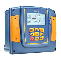
ProMinent DULCOMETER Assembly And Operating Instructions Manual (180 pages)
Multi-parameter Controller diaLog DACa
Brand:
ProMinent
| Category:
Controller
| Size: 5.12 MB
Table of Contents
Table of Contents
3
1 Operating Concept
8
Functions of the Keys
11
Changes the Set Operating Language
12
Acknowledging Error or Warning Messages
13
Key Lock
13
2 Entries in the [Menu] Display
14
3 ID Code
15
A Complete Measuring Station May Comprise the Following
17
4 Safety and Responsibility
18
Explanation of the Safety Information
18
General Safety Notes
19
Intended Use
20
Users' Qualifications
21
5 Functional Description
23
6 Assembly and Installation
24
Scope of Supply
26
Mechanical Installation
26
Wall Mounting
26
Control Panel Installation
28
Electrical Installation
31
Specification of the Threaded Connectors
32
Terminal Diagram
33
Cable Cross-Sections and Cable End Sleeves
42
Wall Mounting and Control Panel Installation
43
Switching of Inductive Loads
44
Connect the Sensors Electrically to the Controller
45
Priming to Bleeding
49
7 Commissioning
50
Switch-On Behaviour During Commissioning
50
Adjusting the Backlight and Contrast of the Controller Display
51
Resetting the Operating Language
51
Defining Metering and Control Processes
51
8 Setting Measured Variables
52
Information on the Measured Variables
54
Measured Variable Ph [MV]
54
Temperature
54
Measured Variable Ph [Ma]
55
ORP [MV], ORP [Ma]
55
Chlorine, Bromine, Chlorine Dioxide, Chlorite, Dissolved Oxygen and Ozone
56
Fluoride Measured Variable
58
Peracetic Acid
58
Hydrogen Peroxide
59
Conductivity [Ma]
59
Temperature [Ma], (as Main Measured Variable)
59
Ma General
60
Features of the Two-Channel Version
60
9 Calibration
61
Calibrating the Ph Sensor
62
Selecting the Calibration Process for Ph
65
2-Point Ph Sensor Calibration (CAL)
66
Ph Sensor Calibration (CAL) with an External Sample (1-Point)
70
Calibration of the Ph Sensor (CAL) by [Data Input]
73
Calibrating the ORP Sensor
76
Selecting the Calibration Process for ORP
76
1-Point Calibration of ORP Sensor (CAL)
76
Calibration Data for ORP Sensor (CAL)
78
Calibrating the Fluoride Sensor
80
Selection of the Calibration Process for Fluoride
80
2-Point Fluoride Sensor Calibration (CAL)
80
1-Point Fluoride Sensor Calibration (CAL)
82
Calibrating Amperometric Sensors
84
Selecting the Calibration Process for Amperometric Measured Variables
85
Calibrating the Slope
85
Calibration of Zero Point
88
Calibrating Oxygen Sensors
90
Selection of the Calibration Process for the Measured Variable O
91
Selection of the Calibration Process for the Measured Variable DO
92
Zero Point Calibration for the Measured Variable DO
94
DO Value Calibration for the Measured Variable DO
96
Measured Value [Ma General] Calibration
98
Calibrating Conductivity
98
Calibrating Temperature
99
10 Setting the [Control]
101
Control Parameter [Type]
108
Control Parameter [System Response]
109
Control Parameter [Setpoint]
109
Control Parameter [Xp]
110
Control Parameter [Ti]
111
Control Parameter [Td]
111
Control Parameter [Add. Basic Load]
111
Control Parameter [Checkout Time]
111
Control Parameter [Max. Ctrl Var.]
111
Interference Variable
111
Remote Setpoint Via a 0/4
114
Parameter Switch] Via the Digital Input or [Timer]
116
11 Setting the [Limit Values]
120
Function of the Limit Values
120
Setting Limit Value Channel 1
122
Setting [Limit 1]
123
Setting [Limit 2]
123
Setting [System Response]
124
12 Setting the [Pumps]
125
Setting [Pump 1]
125
13 Setting the [Relays]
128
Setting Relay 1
128
Function Description [Off]
131
Functional Description of [Relay Timer]
131
Function Description [Limit 1] or [Limit 2]
131
Functional Description of [Limit Value 1/2 (Control Variable)]
131
Function Description of [Cycle]
131
Functional Description of [Pulse Length (PWM)]
132
14 Setting [Digital Inputs]
133
Setting [Digital Input 1]
133
15 Setting the [Ma Outputs]
136
Setting the [Ma Outputs]
138
16 Function: Data Logger
140
Activating, Reading and Deleting Log Books
140
Configuring Log Books
141
Using the [Calibration Log Book]
141
Using the [Error Log Book]
142
Using the [Data Log Book] (Optional)
143
17 Diagnostics
146
Displaying [Logbooks]
146
Displaying the [Calibration Log Book]
146
Reading the [Error Log Book]
146
Displaying [Simulation]
147
Displaying [Device Information]
147
Error Messages and Warning Alerts
148
Help Texts
155
18 Service
157
Setting the [Wash Timer]
157
19 Setting [Device Setup]
158
Setting the [Language]
159
Setting [Device Configuration]
160
Setting the [Extended Configuration]
160
Update
161
Setting the [Access Code]
162
20 Controller Technical Data
163
21 Spare Parts and Accessories
166
Spare Parts
166
Accessories
167
22 Required Formalities
168
Disposal of Used Parts
168
Standards Complied with and Conformity Declaration
168
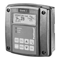
ProMinent DULCOMETER Assembly And Operating Instructions Manual (124 pages)
Compact Controller Measurement: Inductive conductivity
Brand:
ProMinent
| Category:
Controller
| Size: 6.9 MB
Table of Contents
Table of Contents
4
1 Identity Code
7
2 Introduction
9
Measured Variables
9
3 Safety and Responsibility
11
Labelling of Warning Information
11
General Safety Information
12
Intended Use
14
User Qualification
15
4 Functional Description
17
5 Assembly and Installation
18
Scope of Delivery
18
Assembly (Mechanical)
20
Wall Mounting
20
Pipe Mounting
21
Control Panel Mounting
22
Installation (Electrical)
30
Cable Cross-Sections and Cable End Sleeves
31
Electrical Connection of the Conductivity Sensor
31
Terminal Diagram / Wiring
32
Installation (Electrical)
39
Switching of Inductive Loads
40
6 Sensor Connector
42
7 Commissioning
45
Initial Commissioning
45
Setting the Control During Commissioning
45
Selecting the Sensor Type
46
Temperature Compensation and Reference Temperature
48
8 Operating Diagram
50
Overview of Equipment/Operating Elements
50
Entering Values
51
Adjusting Display Contrast
52
Continuous Display
53
Information Display
54
Password
55
9 Operating Menus
56
Calibrating [CAL] the Conductivity Sensor
56
Calibration of the Cell Constant
58
Calibration of the Temperature Coefficient
61
Calibrating the Zero Point
64
Setting Limit Values [LIMITS]
66
Setting the Control [CONTROL]
69
Setting Inputs [INPUT]
72
Setting the [MANUAL] Sensor in the [INPUT] Menu
77
Setting Outputs [OUTPUT]
81
Setting the [DEVICE]
85
10 Control Parameters and Functions
87
DULCOMETER Com- Pact Controller Function States
87
STOP/START] Key
89
Priming [PRIME]
90
Hysteresis Limit Value
91
Temperature Correction Variable
92
Checkout Time for Measured Variable and Correction Variable
93
Checkout Time Control
93
Power Relay "P-REL" as Limit Value Relay
94
Setting and Functional Description of "Relay Used as a Solenoid Valve
95
Alarm Relay
97
Error Logger" Operating Mode
97
11 Maintenance
98
Error Messages
98
Changing the Fuse, DULCOMETER ® Compact Controller
102
12 Technical Data on DULCOMETER ® Compact Controller
103
Permissible Ambient Conditions
103
Dimensions and Weights
103
Material Data
104
Chemical Resistance
104
Sound Pressure Level
104
13 Electrical Data
105
14 Spare Parts and Accessories
109
15 Replacing Spare Part Units
110
Replacing the Top Part of the Housing
110
Replacing the Lower Part of the Housing (Wall/Tube Retaining Bracket)
112
Replacing the Lower Part of the Housing (Control Panel Installation)
115
16 Standards Complied with and Declaration of Conformity
118
17 Disposal of Used Parts
119
18 Index
120
Advertisement
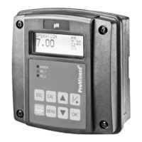
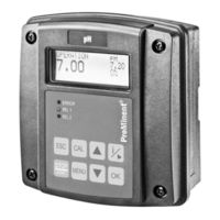
ProMinent DULCOMETER Assembly And Operating Instructions Manual (108 pages)
Compact Controller Measured variable: pH / ORP
Brand:
ProMinent
| Category:
Controller
| Size: 2.36 MB
Table of Contents
Table of Contents
3
1 Identity Code
6
2 Introduction
8
Explanation of the Safety Information
8
Users' Qualifications
10
3 Safety and Responsibility
12
General Safety Information
12
Correct and Proper Use
13
4 Functional Description
15
Flow Diagram
16
Overview of the First Level Menu
17
5 Assembly and Installation
20
Scope of Delivery
22
Mounting (Mechanical)
22
Wall Mounting
22
Pipe Mounting
24
Control Panel Mounting
25
Installation (Electrical)
33
Cable Cross-Sections and Cable End Sleeves
34
Installation of Coaxial Cable to Guard Terminal XE1
34
Installation (Electrical)
39
Switching of Inductive Loads
40
6 Commissioning
42
Initial Commissioning
42
Selection of the Measured Variable
42
Setting the Controller During Commissioning
42
7 Operating Diagram
44
Overview of Equipment/Control Elements
44
Adjusting Display Contrast
45
Continuous Display
46
Info Display
46
Password
48
8 Operating Menus for the Measured Variables Ph and ORP
49
Ph Sensor Calibration (CAL)
49
Redox Sensor Calibration (CAL)
57
Setting Limit Values [LIMITS]
59
Setting the Control [CONTROL]
61
Input Setting (INPUT)
64
Output Setting (OUTPUT)
67
DEVICE Setting
71
9 Control Parameters and Functions
72
DULCOMETER Compact Controller Function States
72
STOP/START Key
74
Priming (PRIME)
75
Hysteresis Limit
76
Temperature Correction Variable for Ph
77
Checkout Time for Measured Variable and Correction Variable
78
Checkout Time Control
78
Power Relay "P-REL" as Limit Value Relay
79
Setting and Functional Description of "Relay Used as a Solenoid Valve
80
Alarm Relay
82
Error Logger" Operating Mode
82
10 Maintenance
83
Changing the Fuse, DULCOMETER ® Compact Controller
83
Fault Reporting and Troubleshooting
84
11 Technical Data DULCOMETER ® Compact Controller
87
Permissible Ambient Conditions
87
Sound Pressure Level
87
Material Data
88
Chemical Resistance
88
Dimensions and Weights
89
12 Electrical Data
90
13 Spare Parts and Accessories
93
14 Replacing Spare Part Units
94
Replacing the Top Part of the Housing
94
Replacing the Lower Part of the Housing (Wall/Tube Retaining Bracket)
96
Replacing the Lower Part of the Housing (Control Panel Installation)
98
15 Standards Complied with and Declaration of Conformity
102
ProMinent DULCOMETER Assembly And Operating Instructions Manual (104 pages)
Measured variable: Chlorine
Brand:
ProMinent
| Category:
Controller
| Size: 2.04 MB
Table of Contents
Table of Contents
3
1 Identity Code
6
2 Introduction
8
Explanation of the Safety Information
8
Users' Qualifications
10
3 Safety and Responsibility
12
General Safety Information
12
Correct and Proper Use
14
4 Functional Description
15
Overview of the First Level Menu
16
5 Assembly and Installation
19
Scope of Delivery
20
Mounting (Mechanical)
20
Wall Mounting
20
Pipe Mounting
22
Control Panel Mounting
23
Installation (Electrical)
31
Cable Cross-Sections and Cable End Sleeves
32
Electrical Connection of the Chlorine Sensor
32
Terminal Diagram / Wiring
33
Installation (Electrical)
38
Switching of Inductive Loads
39
6 Commissioning
41
Initial Commissioning
41
Setting the Controller During Commissioning
41
7 Operating Diagram
42
Overview of Equipment/Control Elements
42
Adjusting Display Contrast
43
Continuous Display
43
Info Display
44
Password
45
8 Operating Menus
46
Calibrating (CAL) the Chlorine Sensor
46
Sensor Slope Calibration
48
Calibrate Sensor Zero Point [CHECK ZERO]
51
Commissioning a New Sensor
52
Setting Limit Values [LIMITS]
53
Setting the Control [CONTROL]
55
Input Setting (INPUT)
58
Output Setting (OUTPUT)
61
DEVICE Setting
65
9 Control Parameters and Functions
66
DULCOMETER Compact Controller Function States
66
STOP/START Key
68
Priming (PRIME)
69
Hysteresis Limit
70
Temperature Correction Variable
70
Checkout Time for Measured Variable and Correction Variable
72
Checkout Time Control
72
Power Relay "P-REL" as Limit Value Relay
73
Setting and Functional Description of "Relay Used as a Solenoid Valve
74
Alarm Relay
76
Error Logger" Operating Mode
76
10 Maintenance
77
Changing the Fuse, DULCOMETER Com- Pact Controller
77
Error Messages
78
11 Technical Data DULCOMETER ® Compact Controller
81
Permissible Ambient Conditions
81
Sound Pressure Level
81
Material Data
82
Chemical Resistance
82
Dimensions and Weights
83
12 Electrical Data
84
13 Spare Parts and Accessories
87
14 Replacing Spare Part Units
88
Replacing the Top Part of the Housing
88
Replacing the Lower Part of the Housing (Wall/Tube Retaining Bracket)
90
Replacing the Lower Part of the Housing (Control Panel Installation)
92
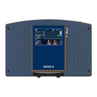
ProMinent DULCOMETER Installation And Configuration Manual (92 pages)
Measuring and Control Unit AEGIS S for Cooling Water Applications
Brand:
ProMinent
| Category:
Measuring Instruments
| Size: 14 MB
Table of Contents
Table of Contents
3
1 Introduction
5
2 Safety and Responsibility
6
Labelling of Warning Information
6
General Safety Information
7
Intended Use
8
User Qualification
9
Network Security
10
3 Storage and Transport
11
4 Assembly and Installation
12
Wall Mounting
12
Control Panel Mounting
14
Electrical Installation
15
Cable Cross-Sections and Cable End Sleeves
15
Preparation
16
Connecting the Terminals
18
Primary Power Connection
18
Connection of Measuring Inputs
18
PT100 / Pt1000 Input RI1
19
Conductivity Input RI2
19
Isolated Analog Inputs 4
20
Digital Inputs DI1 to DI5
21
Serial Input SI1
22
Self-Powered Relay PO1
22
Potential-Free Relays (FO1 to FO4)
22
Electronic Relay Outputs Connections RO1
24
Ma Outputs (AO1 to AO2)
25
Power Supply Output (PWR)
25
RS485 Communication Bus Connections
26
Connection to a USB Port of a Computer
26
Polarization and Termination of the RS485 Bus
27
5 Commissioning
28
Connection to Modem
28
6 Display Mode and Type
30
Main Screen
30
Operating Graph
33
7 General Menu
34
Setup Menu
34
Options
34
Analog Input Settings
37
Digital Input Settings
40
Measurement Settings
41
Output Settings
44
Conditions & Funcions
48
Communication
49
Factory Reset
56
Settings
57
Tower Management
58
Biocide a Timers
59
Biocide B Timers
60
Setpoint Alarms
61
Tank Level
64
Outputs 4
65
Calibration
66
User Menu
67
General Configuration
68
Display
69
Date & Time
69
Language
70
Usb
70
Input Test
71
Output Test
72
Info
72
8 Maintenance and Repair
74
Backup Battery Exchange
74
9 Technical Data
75
Technical Characteristics
75
Radio Technologies in Equipment
77
10 Standards Complied with and Declaration of Conformity
78
11 Modbus Communication Register
79
Address of Modbus Registers
79
Data Formatting
85
12 Index
88
ProMinent DULCOMETER Assembly And Operating Instructions Manual (95 pages)
Compact Controller pH/redox measured variable
Brand:
ProMinent
| Category:
Controller
| Size: 2.26 MB
Table of Contents
Table of Contents
3
1 Introduction
5
Explanation of the Safety Information
5
Users' Qualifications
7
2 Safety and Responsibility
9
General Safety Information
9
Correct and Proper Use
10
3 Functional Description
12
Flow Diagram
13
Overview of the First Level Menu
14
4 Mounting and Installation
17
Scope of Delivery
19
Mounting (Mechanical)
19
Wall Mounting
19
Pipe Mounting
21
Control Panel Mounting
22
Installation (Electrical)
30
Cable Cross-Sections and Cable End Sleeves
31
Installation of Coaxial Cable to Guard Terminal XE1
31
Installation (Electrical)
36
Switching of Inductive Loads
36
5 Commissioning
39
Initial Commissioning
39
Selection of the Measured Variable
39
Setting the Controller During Commissioning
39
6 Operating Diagram
41
Overview of Device /Control Elements
41
Adjusting Display Contrast
42
Continuous Display
43
Info Display
43
Password
45
7 Operating Menus for the Ph and Redox Measured Variables
46
Ph Sensor Calibration (CAL)
46
Redox Sensor Calibration (CAL)
54
Limit Value Setting (LIMITS)
56
Control Setting (CONTROL)
58
Input Setting (INPUT)
61
Output Setting (OUTPUT)
64
DEVICE Setting
68
8 Control Parameters and Functions
69
DULCOMETER Compact Controller Function States
69
STOP/START Key
71
Priming (PRIME)
72
Hysteresis Limit
73
Temperature Correction Variable for Ph
74
Checkout Time Measurement Variable and Correction Variable
75
Checkout Time Control
75
Power Relay "P-REL" as Limit Value Relay
76
Setting and Functional Description of "Relay Used as a Solenoid Valve
77
Alarm Relay
79
Error Logger" Operating Mode
79
9 Maintenance
80
Changing the Fuse, DULCOMETER ® Compact Controller
80
Fault Reporting and Troubleshooting
81
10 Technical Data DULCOMETER® Compact Controller
84
Permissible Ambient Conditions
84
Sound Pressure Level
84
Material Data
85
Chemical Resistance
85
Dimensions and Weights
86
11 Electrical Data
87
12 Spare Parts and Accessories
90
13 Standards Complied with
91
14 Disposal of Used Parts
92
15 Declaration of Conformity
93
16 Index
94
Advertisement
Related Products
ProMinent DULCOMARIN II
ProMinent DULCOMETER Aegis-II
ProMinent DULCOMETER Compact
ProMinent DULCOMETER diaLog DACb
ProMinent DULCOMETER D1Cb
ProMinent DULCOMETER D1Cc
ProMinent DULCOMETER D1C
ProMinent DCM 2 Series
ProMinent DULCOMETER D1CA
ProMinent diaLog DACb
ProMinent Categories
Water Pump
Controller
Measuring Instruments
Industrial Equipment
Accessories
More ProMinent Manuals
Login
Sign In
OR
Sign in with Facebook
Sign in with Google
Upload manual
Upload from disk
Upload from URL