ProMinent DULCOMETER Assembly And Operating Instructions Manual
Compact controller ph/redox measured variable
Hide thumbs
Also See for DULCOMETER:
- Assembly and operating instructions manual (185 pages) ,
- Installation and configuration manual (92 pages) ,
- Assembly and operating instructions manual (180 pages)
Table of Contents
Advertisement
Quick Links
Assembly and operating instructions
DULCOMETER
Compact Controller
®
pH/redox measured variable
A0206
Please carefully read these operating instructions before use! · Do not discard!
The operator shall be liable for any damage caused by installation or operating errors!
Technical changes reserved.
Part no. 986214
BA DM 190 10/11 EN
Advertisement
Table of Contents

Related Manuals for ProMinent DULCOMETER


Summary of Contents for ProMinent DULCOMETER
- Page 1 Assembly and operating instructions DULCOMETER Compact Controller ® pH/redox measured variable A0206 Please carefully read these operating instructions before use! · Do not discard! The operator shall be liable for any damage caused by installation or operating errors! Technical changes reserved.
- Page 2 ProMinent Dosiertechnik GmbH Im Schuhmachergewann 5 - 11 69123 Heidelberg Telephone: +49 6221 842-0 Fax: +49 6221 842-419 email: info@prominent.de Internet: www.prominent.com 986214, 2, en_GB © 2011...
-
Page 3: Table Of Contents
Table of contents Table of contents Introduction......................5 1.1 Explanation of the safety information............. 5 1.2 Users' qualifications..................7 Safety and responsibility..................9 2.1 General Safety Information................9 2.2 Correct and proper use................10 Functional description................... 12 3.1 Flow diagram....................13 3.2 Overview of the first level menu.............. - Page 4 8.9 Setting and functional description of "Relay Used as a Solenoid Valve" ..77 8.10 Alarm relay....................79 8.11 "Error logger" operating mode..............79 Maintenance......................80 9.1 Changing the fuse, DULCOMETER ® Compact Controller......80 9.2 Fault reporting and troubleshooting.............. 81 Technical data DULCOMETER ®...
-
Page 5: Introduction
Nature and source of the danger DULCOMETER ® Compact Controller pH / Consequence: Fatal or very serious redox measured variable. injuries. Order number DULCOMETER ® Compact Measure to be taken to avoid this Controller pH / redox measured variable: danger 1035638 Danger! –... - Page 6 Introduction Type of information CAUTION! Hints on use and additional informa‐ Nature and source of the danger tion Possible consequence: Slight or minor injuries, material damage. Source of the information, additional measures Measure to be taken to avoid this danger Information! Caution! Denotes hints on use and other...
-
Page 7: Users' Qualifications
Trained user A trained user is a person who fulfils the requirements made of an instructed person and who has also received additional training specific to the system from ProMinent or another authorised distribution partner. Trained qualified per‐ A qualified employee is deemed to be a person who is able to sonnel assess the tasks assigned to him and recognize possible haz‐... - Page 8 Customer Service department refers to service technicians, department who have received proven training and have been authorised by ProMinent to work on the system. Note for the system operator The pertinent accident prevention regulations, as well as all other generally acknowl‐...
-
Page 9: Safety And Responsibility
Safety and responsibility Safety and responsibility General Safety Information WARNING! Operating errors! WARNING! Possible consequence: Fatal or very Live parts! serious injuries Possible consequence: Fatal or very – The unit should only be operated serious injuries by adequately qualified and tech‐ –... -
Page 10: Correct And Proper Use
Safety and responsibility NOTICE! NOTICE! Correct and proper use Correct sensor operation Damage to the product or its sur‐ Damage to the product or its sur‐ roundings roundings – The unit is not intended to – Correct measuring and dosing is measure or regulate gaseous or only possible if the sensor is solid media... - Page 11 Safety and responsibility NOTICE! Correct and proper use The unit is intended to measure and regulate liquid media. The marking of the measured variables is located on the controller and is absolutely binding. The unit may only be used in accord‐ ance with the technical details and specifications provided in this oper‐...
-
Page 12: Functional Description
Functional description Functional description Brief functional description Applications: Waste water treatment The DULCOMETER Compact Controller ® for pH and redox measured variables pro‐ Treatment of drinking water vides basic functions for water treatment Swimming pool water treatment applications. It has a fixed configuration... -
Page 13: Flow Diagram
Functional description Flow diagram Input Input Contact input for temperature as measured value PAUSE / HOLD correction variable from the sensor Correction Corrected measured value STOP START Control Limit value (P or PID) monitoring Limit Actuating variable (PWM) Frequency relay Power relay (f-REL) mA Output... -
Page 14: Overview Of The First Level Menu
Functional description Overview of the first level menu OPERATION STOP 6.20 7.20 CAL pH 6.20 7.20 STOP START LIMIT ↓ LIMIT ↓ 80.0 °C 80.0 °C MENU ≡MENU LIMITS LIMITS SETUP CONTROL INPUT ≡MENU LIMITS CONTROL SETUP CONTROL INPUT ≡MENU LIMITS INPUT SETUP CONTROL... - Page 15 Functional description Display view Selection Reference Function with: Ä Chapter 7.1 ‘pH The calibration menu enables cali‐ CAL pH ZERO 0.00 mV sensor calibration bration of controller and sensor. SLOPE 59.16 mV/pH OK CAL=START (CAL)’ on page 46 A0332 OPERATION 6.20 7.20 80.0 °C...
- Page 16 Functional description Display view Selection Reference Function with: Ä Chapter 7.6 Enables setting of the mA output ≡MENU CONTROL ‘ Output setting parameter. INPUT OUTPUT (OUTPUT)’ A0330 on page 64 Ä Chapter 7.7 Enables adjustment of the pass‐ ≡MENU INPUT ‘DEVICE setting’...
-
Page 17: Mounting And Installation
Ensure that there is unimpeded part of the housing cannot absorb access for operation high mechanical loading. When – Secure, low-vibration fixing working on the DULCOMETER ® – Avoid direct sunlight Compact Controller, firmly hold the – Permissible ambient temperature top section of the controller housing. - Page 18 Mounting and installation Mounting position Leave sufficient free space for the – cables Packaging material Dispose of packaging material envi‐ ronmentally. All packaging compo‐ nents are provided with their corre‐ sponding recycling...
-
Page 19: Scope Of Delivery
Mounting and installation Scope of delivery The following parts belong to the standard scope of delivery of a DULCOMETER ® Com‐ pact Controller. Description Quantity Assembled device Cable connection set DMTa/DXMa (metr.) Operating instructions Mounting (mechanical) The DULCOMETER ® Compact Controller is suitable for mounting on a wall, a pipe or a control panel. - Page 20 ® Compact Controller at the top in the wall/pipe bracket and push using light pressure at the bottom against the wall/pipe bracket. Then press upwards until the DULCOMETER ® Compact Controller audibly snaps into position. A0273 Fig. 3: Removing the wall/pipe bracket Remove the wall/pipe bracket.
-
Page 21: Pipe Mounting
Pipe diameter: 25 mm to 60 mm. A0275 Fig. 6: Suspend and secure the DULCOMETER Compact Controller ® Suspend the DULCOMETER ® Compact Controller at the top (1) in the wall/pipe bracket and push using light pressure at the bottom (2) against the wall/pipe bracket. -
Page 22: Control Panel Mounting
Mounting and installation 4.2.3 Control panel mounting Mounting kit for control panel installation of the DULCOMETER Compact Controller: ® Order number 1037273 Description Quantity Drilling template sheet 3872-4 PT-Screw (3.5 x 22) Profile seals Strain relief strip DF3/DF4 PT-Screw (3.5 x 10) - Page 23 Mounting and installation Preparing the control panel A0347 Fig. 7: The drawing is not true to scale and will not be updated. It is for information only Outline contour of the DULCOMETER Compact Controller ®...
- Page 24 Mounting and installation Mark the exact position of the DULCOMETER ® Compact Controller on the control panel using the drilling template (drawing no. 3872-4) Core hole The 3.5 mm Ø must absolutely be adhered to as a core hole diameter for screwing in the fixing bolts.
- Page 25 To disconnect the ribbon cable the socket lock (3) must be opened, see Fig. 8 Fig. 8: Disconnecting the ribbon cable Undo four screws and open the DULCOMETER ® Compact Controller Open the right and left lock (3) (arrow) at the socket and pull the ribbon cable (1) out of the socket Using pliers, break off the catches (2 and 4).
- Page 26 Mounting and installation Fig. 9: Remove the hinge Remove the screw (2), unclip the hinge (1) on the controller housing bottom sec‐ tion (arrows) and remove the hinge...
- Page 27 ® (1) must be arranged as shown in the figure ð The profile seal must uniformly surround the housing upper edge. From the rear, position the DULCOMETER ® Compact Controller controller housing bottom section with profile seal in the cutout and secure it using the three screws...
- Page 28 Mounting and installation A0351 Fig. 11: Fitting the profile seal on the controller housing top section Position the profile seal (arrow) uniformly in the groove of the DULCOMETER ® Compact Controller controller housing top section. The clips (3) must be arranged...
- Page 29 Fig. 12: Push and lock the ribbon cable in the socket Push and lock the ribbon cable (1) in the socket Screw the controller housing top section onto the controller housing bottom section of the DULCOMETER ® Compact Controller Once again check the seating of the profile seals...
-
Page 30: Installation (Electrical)
(emergency-off switch, etc.) is the responsibility of the plant operator The signal leads of the DULCOMETER Compact Controller ® must not be routed alongside faulty cabling. Faults could lead to malfunc‐ tions of the DULCOMETER Com‐ ® pact Controller. -
Page 31: Cable Cross-Sections And Cable End Sleeves
Mounting and installation 4.3.1 Cable Cross-Sections and Cable End Sleeves Minimum cross-sec‐ Maximum cross- Stripped insulation tion section length Without cable end 0.25 mm 1.5 mm sleeve Cable end sleeve 8 - 9 mm 0.20 mm 1.0 mm without insulation Cable end sleeve 10 - 11 mm 0.20 mm... - Page 32 Mounting and installation 4.3.2.1 Terminal diagram / wiring A0348 Fig. 14: Threaded connector number Wiring Threade Descrip‐ Ter‐ Terminal Function Recom‐ Remarks d con‐ tion minal mended number nector cable ⌀ Descrip tion Size ph/redox XE 1 Ref. El. ⌀ 5 Guide redox cable...
- Page 33 (f-relay) trolled metering pump * To achieve protection class IP 67 please use original Prominent cable, part number 1036759 *** When using as a potential equaliser, the short circuit bridge must be removed! Relay Solenoid ⌀ 5 Guide...
- Page 34 Mounting and installation Threade Descrip‐ Ter‐ Terminal Function Recom‐ Remarks d con‐ tion minal mended number nector cable ⌀ Descrip tion Size ** An RC suppressor must be connected (not part of the scope of delivery) Mains XP 1 85 ... ⌀...
- Page 35 Mounting and installation Terminal diagram pH/Redox ORP Temperatur (Pt1000) Potenzialausgleich Temperatur (Pt1000) Digital Eingang "Pause" Normsignal-Ausgang 0/4-20mA (Schreiber,Stellglied) Extern Pumpe heben/senken Magnetventil heben/senken Grenzwertrelais, Stellglied Relais (Alarm) A0361 Fig. 15: Terminal diagram...
-
Page 36: Installation (Electrical)
Mounting and installation Insert the reducing inserts in the 4.3.3 Installation (electrical) threaded connections according to the cable cross sections used Guide the cables into the threaded connections The cable must be routed in a site- provided cable duct to ensure strain Tighten the clamping nuts of the relief threaded connections so that they... - Page 37 Mounting and installation When switching off, the connection in The switching-off process can be investi‐ series of a resistor and capacitor means gated and documented using an oscillo‐ that the current can fade out in a damped scope. The voltage peak at the switch oscillation.
- Page 38 Mounting and installation Typical AC current application with an inductive load: 1) Load (e.g. alpha motorised pump) 2) RC-protective circuit – Typical RC protective circuit at 230 V AC: [0.22µF/X2] – Capacitor [100 ohm / 1 W] (Metal- – Resistor oxide (pulse-resistant)) 3) Relay contact (XR1, XR2, XR3)
-
Page 39: Commissioning
– The sensor must be calibrated functions. after commissioning Setting the controller during Following completion of mechanical and commissioning electrical assembly, the DULCOMETER ® Compact Controller should be integrated into the measuring point. NOTICE! Reset to factory settings Initial commissioning... - Page 40 Commissioning The DULCOMETER Compact Controller ® ‘one-way’ . Only one position only controls or one negative control variable can be calculated. The direction of the control ‘PUMP’ menu. There variable is set in the is no dead zone. In this sense, control ‘switched off’...
-
Page 41: Operating Diagram
Operating diagram Operating diagram Overview of device /Control elements Ä Chapter 1.2 ‘Users' qualifications’ on page 7 Users' qualification: trained user, see A0291 Fig. 19: Overview of device /Control elements Function Description 1. Measured variable Affix the measured variable label here 2. -
Page 42: Adjusting Display Contrast
Shows the activated state of the P-relay 13. ERROR LED Indicates a controller error state. A text message is displayed simultaneously in the LCD continuous display Adjusting display contrast If the DULCOMETER Compact Controller ® ‘continuous display’ , you can set is set to the contrast of the LCD-display. -
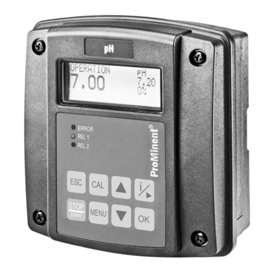
Page 43: Continuous Display
Operating diagram Continuous display A0285 Fig. 20: Continuous display Measured variable Temperature (Correction variable) Setpoint Measured value (actual value) Control variable Mode Possible error text: e.g. "Limit↓" (Direction of the limit value transgres‐ sion, e.g. here lower limit value trans‐ gression) Info display In the info display, the most important parameters for each menu item of the first menu... - Page 44 [VOLTAGE]: currently measured sensor mV value – [GLASSRES]: measured glass resistance of connected pH sensors for media – temperatures of 15 °C to 80 °C. The displayed value is only valid when used with ProMinent pH sensors [BOARDTEMP]: Current housing interior temperature –...
-
Page 45: Password
Operating diagram Password Access to the setting menu can be limited using a password. The DULCOMETER ® Com‐ ‘5000’ . Using the preset password ‘5000’ pact Controller is supplied with the password the DULCOMETER Compact Controller is setup so that all menus can be accessed ®... -
Page 46: Operating Menus For The Ph And Redox Measured Variables
Operating menus for the pH and redox measured variables Operating menus for the pH and redox measured variables Ä Chapter 1.2 ‘Users' qualifications’ Users' qualification: Instructed person, see on page 7 STOP OPERATION CAL pH 6.20 7.20 6.20 7.20 STOP START LIMIT ↓... - Page 47 ‘0’ . Exception to this: a basic load or a manual control variable has been set. This remains active. The mA standard signal output is frozen. When calibration/testing has been completed successfully, all of the error checks relating to the reading are restarted. The DULCOMETER ® Compact Controller saves all the determined data for zero point and slope when the calibration is successful.
- Page 48 Operating menus for the pH and redox measured variables 2-Point Calibration OPERATION CAL pH 6.20 7.20 ZERO 0.00 mV SLOPE 59.16 mV/pH OK LIMIT ↓ 25.0 °C CAL=START CAL pH BUFFER TEMP= 025.0 °C pH 7 Zero 7.00 pH (6,00...8,00 pH) CAL=START pH 7.00 SENSOR = 3 mV...
- Page 49 Operating menus for the pH and redox measured variables Valid calibration values Valid calibration: Zero point -60 mV…+60 mV – Slope 40 mV/pH…65 mV/pH – Two test containers with a buffer solution are required for calibration. The pH value of the buffer solutions should be at least 1.5 pH units apart.
- Page 50 Operating menus for the pH and redox measured variables The determined values for the zero point and slope are displayed ‘ZERO’ and ð The calibration is now saved as successful if the values for ‘SLOPE’ are both ‘OK’ . Incorrect calibration Should the result of the calibration lie outside the specified tolerance limits, an error message appears ‘ERR’...
- Page 51 Operating menus for the pH and redox measured variables 1-Point slope calibration CAL pH OPERATION 6.20 7.20 ZERO 0.00 mV SLOPE 59.16 mV/pH OK LIMIT ↓ 25.0 °C CAL=START CAL pH BUFFER TEMP= 025.0 °C pH 7 7.00 pH CAL=START pH 7.00 SENSOR = 3 mV ZERO -3.37mV...
- Page 52 Operating menus for the pH and redox measured variables ‘TEMP’ is set to ‘auto’ or ‘manual’ ), If temperature has been selected (only if then set the buffer temperature with the keys Confirm the entry by pressing the key or ‘ZERO’...
- Page 53 Operating menus for the pH and redox measured variables Single point zero point calibration CAL pH OPERATION 6.20 7.20 ZERO 0.00 mV SLOPE 59.16 mV/pH OK LIMIT ↓ 25.0 °C CAL=START CAL pH BUFFER TEMP= 025.0 °C pH 7 Zero (6,00...8,00 pH) 7.00 pH CAL=START...
-
Page 54: Redox Sensor Calibration (Cal)
Operating menus for the pH and redox measured variables ‘TEMP’ is set to ‘auto’ or ‘manual’ ), If temperature has been selected (only if then set the buffer temperature with the keys Confirm the entry by pressing the key again ‘ZERO’... - Page 55 – fectly Observe the sensor operating instructions – During the calibration: the DULCOMETER ® Compact Controller sets the control outputs ‘0’ . Exception to this: a basic load or a manual control variable has been set. This remains active. The mA standard signal output is frozen.
-
Page 56: Limit Value Setting (Limits)
Operating menus for the pH and redox measured variables Limit value setting (LIMITS) ≡MENU OPERATION 6.20 7.20 LIMITS MENU CONTROL LIMIT ↓ 25.0 °C INPUT ※LIMITS ※LIMITS LIMIT↑= 7.80 pH LIMIT↑= 7.80 pH LIMIT↓= 6.50 pH TLIMIT↑=120.0 °C ※LIMITS ※LIMITS LIMIT↑= 7.80 pH LIMIT↓= 6.50 pH... - Page 57 Operating menus for the pH and redox measured variables Setting Possible values Display Starting Increment Lower value Upper value Remarks value LIMIT ↑ pH 8.50 pH 0.01 pH 0,00 14,00 upper limit value pH value LIMIT ↓ pH 6.50 pH 0.01 pH 0,00 14,00...
-
Page 58: Control Setting (Control)
Operating menus for the pH and redox measured variables Control setting (CONTROL) ≡MENU OPERATION 6.20 7.20 LIMITS MENU CONTROL LIMIT ↓ 25.0 °C INPUT ※CONTROL ※CONTROL PUMP: dosing↓ PUMP: dosing↓ SET= 7.20 pH dosing↑ TYPE: ※CONTROL ※CONTROL PUMP: dosing↓ SET= 7.20 pH SET= 7.20 pH... - Page 59 Operating menus for the pH and redox measured variables Setting Possible values Starting Increment Lower value Upper Remarks value value PUMP dosing ↓ dosing ↓ One-way control direction dosing ↑ 7.20 pH 0.01 pH 0.00 pH 14.00 pH pH setpoint 750 mV 1 mV -1,000 mV...
- Page 60 1 = with one-way control in the upwards direction: 0..+100% (setting with PUMP: dosing↑), in downwards direction: -100..0% (setting with PUMP: dosing↓). 2 = When switching over the metering direction, all actuators in the DULCOMETER ® Compact Controller are reset to the factory settings for the selected metering direction.
-
Page 61: Input Setting (Input)
Operating menus for the pH and redox measured variables Input setting (INPUT) ≡MENU OPERATION 6.20 7.20 LIMITS MENU CONTROL LIMIT ↓ 25.0 °C INPUT ※INPUT ※INPUT SENSOR: SENSOR: ↳CHECK: TEMP: auto ※INPUT ※INPUT no probe SENSOR: ↳CHECK: off ↳CHECK: full test TEMP: auto <... - Page 62 Operating menus for the pH and redox measured variables Setting Possible values Display Starting Increment Lower Upper Remarks value value value Sensor Process variables switchover pH <--> redox ↳CHECK Sensor monitoring ‘off’ < 1 MΩ Sensor break check (glass break) no probe Check for pres‐...
- Page 63 Monitoring for sensor breakage: The sensor breakage check (glass breakage) identifies a defective sensor due to its low internal resistance. Correctly functioning pH sensors have very high resistances with internal resistances in the high MΩ range. The DULCOMETER Compact Controller is capable of recognising broken sensors from their ®...
-
Page 64: Output Setting (Output)
Operating menus for the pH and redox measured variables Output setting (OUTPUT) ≡MENU OPERATION 6.20 7.20 INPUT OUTPUT MENU DEVICE LIMIT ↓ 25.0 °C ※OUTPUT ※OUTPUT alarm P-REL: alarm unused P-REL: f-REL : dosing dosing ↳ limit PUMPMAX=180/min ※OUTPUT ※OUTPUT P-REL: alarm f-REL:... - Page 65 Operating menus for the pH and redox measured variables Setting Possible values Starting Increment Lower value Upper Remarks value value P-REL alarm alarm Alarm relay (Power unused relay) dosing PWM relay limit Limit relay ↳PERIOD 60 s 30 s 6000 s Cycle time of the PWM con‐...
- Page 66 Operating menus for the pH and redox measured variables Setting Possible values Starting Increment Lower value Upper Remarks value value ↳PUMPMA 1 rpm Maximum stroke rate of the low power relay (fre‐ quency relay) mA OUT meas val (Output meas val meas val value of the corr val...
- Page 67 Operating menus for the pH and redox measured variables Setting Possible values Starting Increment Lower value Upper Remarks value value ↳0/4 mA 32.0 °F 0.1 °F 32.0 °F 248.0 °F Temp. value assigned 0/4 ↳20 mA 212.0 °F 0.1 °F 32.0 °F 248.0 °F Temp value...
-
Page 68: Device Setting
Operating menus for the pH and redox measured variables DEVICE setting ≡MENU OPERATION 6.20 7.20 INPUT OUTPUT MENU DEVICE LIMIT ↓ 25.0 °C ※DEVICE ※DEVICE PASSWORD: **** 5000 NEW PASSW. RESTART DEVICE 5000=FREE ※DEVICE RESTART!!! PASSWORD: **** RESTART DEVICE A0283 Fig. -
Page 69: Control Parameters And Functions
Control and all other outputs are on page 7 frozen New faults are detected, however they have no effect on the alarm relay DULCOMETER Compact ® or the mA output. However the effect Controller function states of already existing faults (e.g. fault... - Page 70 Control parameters and functions ‘CAL’ (calibration) is started in If the ‘OPERATION’ the function state (normal mode), then the function state ‘ PAUSE/HOLD’ is ignored until the ‘CAL’ (calibration). How‐ end of the ever STOP/START is possible at any time An alarm can be acknowledged as follows: By clearing all fault causes, by pressing the...
-
Page 71: Stop/Start Key
The P-relay acting as an alarm relay activates (no alarm) Restarting the DULCOMETER ® Compact Controller If a STOP state existed, then the DULCOMETER ® Compact Controller must be man‐ ually started after being switched back on. Fault detection starts afresh, all existing faults are deleted... -
Page 72: Priming (Prime)
Control parameters and functions Priming (PRIME) OPERATION STOP PRIME↑↑↑ 6.20 6.20 6.20 7.20 7.20 7.20 LIMIT ↓ LIMIT ↓ LIMIT ↓ 80.0 °C 80.0 °C 80.0 °C A0359 Fig. 34: Priming, e.g. to vent a pump ‘STOP’ and ‘OPERATION’ While the continuous display is visible and within the states ‘PRIME’... -
Page 73: Hysteresis Limit
A0009_GB Fig. 35: Hysteresis Upper limit value = LIMIT↑ Lower limit value = LIMIT↓ The range between LIMIT↑ and LIMIT↓ is the valid measuring range. ‘hysteresis’ . The DULCOMETER ® Compact Controller has fixed Measured variable Hysteresis 0.28 pH Redox 20 mV ‘Hysteresis’... -
Page 74: Temperature Correction Variable For Ph
[off] : No temperature compensation takes place – For measurements which do not require temperature compensa‐ tion [auto] : The DULCOMETER ® Compact Controller evaluates the temperature signal of the connected temperature sensor – For measurements using a tem‐ perature sensor (Pt1000) (0 -120 °C) -
Page 75: Checkout Time Measurement Variable And Correction Variable
TLIMITERR Checkout time of the correction variable If upon elapsing of the checkout time, the valid measuring range is not reached, then the DULCOMETER ® Compact Controller exhibits the following behaviour: LIMIT ERR: The control is switched off. A fault current is output, provided the output is configured as a measured variable output TLIMITERR: The control is switched off. -
Page 76: Power Relay "P-Rel" As Limit Value Relay
Control parameters and functions ‘LIMIT’ can be used to set The parameter a limit for the control variable. If the con‐ trol variable exceeds this limit value, the CHECKTIME fault is triggered (checkout time of the control has elapsed). The con‐ trol is switched to basic load and a fault current output. -
Page 77: Setting And Functional Description Of "Relay Used As A Solenoid Valve
Control parameters and functions Setting and functional description of "Relay Used as a Solenoid Valve" Cycle Solenoid min. time Actuating valve variable: 80 % = 0.80 Cycle Cycle Actuating variable: 50 % = 0.50 Cycle A0025_GB Fig. 36: Solenoid valve (= P-REL: dosing) [MIN ON] min. - Page 78 Fig. 37: Theoretical switching time < min. time [MIN ON] min. time [PERIOD] (in seconds) Cycle The DULCOMETER ® Compact Controller does not switch on for a certain number of ‘min. time’ . Then it cycles until the sum of the theoretical switching times exceeds switches for the duration of this total time.
-
Page 79: Alarm Relay
Control parameters and functions 8.10 Alarm relay ‘OPERATION’ The alarm relay trips in (normal operating mode), if a fault exists, Ä ‘Fault reporting which is shown in the and troubleshooting’ Table on page 81 as ‘ERROR’ and not as a ‘WARNING’ . ALARM error messages shown in the con‐... -
Page 80: Maintenance
Users' qualification: trained user, see Ä Chapter 1.2 ‘Users' qualifications’ The mains fuse is located in a sealed fuse on page 7 holder in the inside of the device. The DULCOMETER ® Compact Controller Disconnect the controller from the is maintenance free. -
Page 81: Fault Reporting And Troubleshooting
Maintenance Fault reporting and troubleshooting Ä Chapter 1.2 ‘Users' qualifica‐ Users' qualification for diagnostics: trained user, see tions’ on page 7 . Further measures depend on the type and scope of possible trou‐ bleshooting measures to be carried out. Fault reporting and troubleshooting Display Description / Measured... - Page 82 Maintenance Display Description / Measured Correction Status Mode cause variable variable output output mA output cur‐ Error RANGE ↓ rent has a lower limit LIMIT ↑ Measured vari‐ Warning able exceeds upper set limit LIMIT ↓ Measured vari‐ Warning able falls below lower set limit T LIMIT ↑...
- Page 83 Maintenance [Mode] Resulting controller mode (relates to control variable and thus, as necessary, mA output) [Measured variable output] Consequence for the current output, if this is set as ‘a measured variable output’ [Correction variable output] Consequence for the current output, if this is set as ‘a correction variable output’...
-
Page 84: Technical Data Dulcometer® Compact Controller
Technical data DULCOMETER® Compact Controller Technical data DULCOMETER Compact Controller ® 10.1 Permissible ambient conditions Degree of protection (IP) The controller fulfils the IP 67 degree of protection requirements (wall/pipe mounting) or IP 54 (control panel mounting). This degree of protection is only achieved if all seals and threaded connectors are correctly fitted. -
Page 85: Material Data
Technical data DULCOMETER® Compact Controller 10.3 Material data Part Material Housing lower and upper section PPE-GF10 Bracket rear side housing bottom section PPE-GF20 Operating film Polyester PET membrane Seal Expanded PUR Cover screws Stainless steel A2 Profile seal (control panel mounting) Silicone 10.4... -
Page 86: Dimensions And Weights
Technical data DULCOMETER® Compact Controller 10.5 Dimensions and weights Complete device: 128 x 137 x 76 mm (W x H x D) Packaging: 220 x 180 x 100 mm (W x H x D) Weight of device without packaging: approx. 0.5 kg Gross weight of device with packaging: approx. -
Page 87: Electrical Data
Electrical data Electrical data Mains connection Nominal voltage range 100 – 230 VAC ±10 % Frequency 50 – 60 Hz Current consumption 50 – 100 mA The mains connection is isolated from other switching parts by reinforced insulation. The device has no mains switch; a fuse is fitted. Power relay (P-relay) Loading of switching contacts 5 A;... - Page 88 Electrical data For the connection of an external semi-conductor or mechanical switch. mA Output 0 - 20 mA 4 - 20 mA manual Current range 0 – 20.5 mA 3.8 – 20.5 mA 0 - 25 mA In the event of 0 or 23 mA 3.6 or 23 mA a fault...
- Page 89 Electrical data Pump control (f-relay) Max. switching voltage: 50 V (protective low voltage) Max. switching current: 50 mA Max. residual current (open): 10 mA Max. resistance (closed): 60 W Max. switching frequency (HW) at 50% 100 Hz filling factor Digital output galvanically isolated from all other connections via OptoMos relay. Temperature input Temperature measuring range: 0...120 °C...
-
Page 90: Spare Parts And Accessories
Spare parts and accessories Spare parts and accessories Spare parts Part number Fine fuse 5x20 T 0.315 A 732404 Wall/pipe bracket 1002502 Guard terminal top section (knurled nut) 733389 Measured variable labels 1002503 DMT tie strap 1002498 Cable connection set DMTa/DXMa 1022312 (metric) Accessories... -
Page 91: Standards Complied With
Standards complied with Standards complied with EN 60529 Specification for degrees of protection provided by enclosures (IP- Code) EN 60746-1 Expression of performance of electrochemical analyzers - Part 1: Gen‐ eral EN 61000 Electromagnetic compatibility (EMC) EN 61010 Safety requirements for elec‐ trical equipment for measurement, control and laboratory use - Part 1: General requirements... -
Page 92: Disposal Of Used Parts
Regulations governing disposal of used parts – Note the current national regula‐ tions and legal standards which apply in your country ProMinent Dosiertechnik GmbH, Heidel‐ berg will take back decontaminated used devices providing that they are covered by adequate postage. -
Page 93: Declaration Of Conformity
Declaration of Conformity Declaration of Conformity Fig. 39: EC Declaration of Conformity... -
Page 94: Index
Noise generation........84 Degree of protection IP 67....17 Non-discriminatory approach....5 Dimensions.......... 86 Drill............25 Operating position........ 18 Drill holes..........20 Order number......... 5 Drilling template........25 Original Prominent cable...... 34 Overview of the Device ....... 41 Error Logger......... 79... - Page 95 Index Sensor monitoring........ 89 Pipe bracket......... 20 Single point zero point calibration..53 Pipe diameter........21 Small threaded connection (M 16 x 1.5)............36 plant rooms.......... 85 Snap-hooks.......... 20 Preparing the control panel....25 Sound Pressure Level......84 Profile seal........... 29 Spare parts..........
Need help?
Do you have a question about the DULCOMETER and is the answer not in the manual?
Questions and answers