Sign In
Upload
Manuals
Brands
ProMinent Manuals
Controller
DULCOMETER D1Cb
ProMinent DULCOMETER D1Cb Manuals
Manuals and User Guides for ProMinent DULCOMETER D1Cb. We have
2
ProMinent DULCOMETER D1Cb manuals available for free PDF download: Assembly And Operating Instructions Manual, Instructions For Assembly And Use
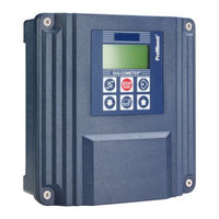
ProMinent DULCOMETER D1Cb Assembly And Operating Instructions Manual (155 pages)
Brand:
ProMinent
| Category:
Controller
| Size: 3.19 MB
Table of Contents
Table of Contents
4
1 Introduction
8
Explanation of the Safety Information
8
Users' Qualifications
10
General Safety Information
11
Correct and Proper Use
13
ID Code
14
2 Functional Description
17
Wall Mounting/Control Panel Installation
18
Electrical Construction
19
Block Circuit Diagram
20
Galvanic Isolation
21
3 D1Cb Mounting
22
Scope of Supply
23
Installation (Wall Mounted)
24
Installation - Control Panel Mounted (Optional)
25
Wall Mounted Installation of D1Cb (Electrical)
27
Opening the Device
28
Electrical Installation (Wall Mounted)
29
Electrical Installation (Control Panel Mounted)
30
Installation of Coaxial Cable to Guard Terminal XE1
31
Cable Cross-Sections and Cable End Sleeves
32
Protective RC Circuit (Optional)
33
Terminal Wiring Diagram
34
Switching of Inductive Loads
38
4 D1Cc Mounting
40
DULCOMETER ® D1Cc Scope of Supply
41
Mounting - Control Panel Installation DULCOMETER ® D1Cc
41
Electrical Installation (Control Panel Mounted)
44
Installation of Coaxial Cable to Guard Terminal XE1
45
Cable Cross-Sections and Cable End Sleeves
47
Terminal Diagram
48
Switching of Inductive Loads
50
5 Commissioning
52
Initial Commissioning
52
Selection of the Operating Language
52
Selection of the Measured Variable and Measuring Range
54
Activation Code for Extended Functions
55
Extended Functions Obtainable with the Activation Code
55
6 Operating Diagram/ Display Symbols
59
Overview of Equipment/Control Elements
59
Display Symbols
60
Permanent Display 1
61
Continuous Display 2
62
Continuous Display 3
62
Operating Diagram
64
Reduced / Complete Operating Menu
67
Fault Messages
67
Fault Display
67
General Settings
68
Access Code
68
7 Measured Variables and Operating Menus for Amperometric Sensors
69
Reduced / Complete Operating Menu
70
Description of All Amperometric Measured Variables
70
Reduced Operating Menu
71
Complete Operating Menu / Description of All Measured Variables
73
Calibration of All Amperometric Measured Variables
74
Calibration of the Sensor for Amperometric Measured Variables
75
Preparation for Calibration of the Sensors for Amperometric Measured Variables
75
Calibration of Zero Point and Slope
76
Setting the Measured Value
79
Correcting Value
79
8 Measured Variables and Operating Menus for Potentiometric Sensors
81
Reduced / Complete Operating Menu
82
Description of Ph, Redox and Fluoride Measured Variables
82
Reduced Ph / Redox / Fluoride Operating Menu
83
Complete Operating Menu/Description of Ph / ORP / Fluoride
85
Calibration of Ph, ORP and Fluoride Sensors
87
Description of the Calibration of Ph Sensors
88
Calibration of Ph Sensors. Description of the Setting Ranges
91
Calibration of Ph Sensors. Description of the Error Messages
91
Testing the Redox Sensor
92
Description of the Calibration of Fluoride Sensors
95
Temperature Correction Value for Ph and Fluoride Sensors
99
9 Measured Variables and Operating Menus for the Standard Signal General
101
Explanation of the Standard Signal General
101
Changing the Measured Variable
103
Reduced / Complete Operating Menu
104
Setting the Reading
104
Description of All Standard Signal Measured Values/Measured Variables
105
Reduced Operating Menu
106
Complete Operating Menu / Description of All Measured Variables
108
Calibrating the Standard Signal
109
Calibration of the Zero Point of the Standard Signal General
110
Two-Point Calibration of the Standard Signal General
111
10 Operating Menus Independent of Measured Variables
113
Pumps
114
Setting the Relays
116
Setting and Functional Description of the Relays
117
Setting the Limits
122
Setting the Control
125
Set Ma Output
129
General Settings
131
Setting the Measured Variable/Measuring Range
131
Sub-Functions of the "General Settings" Menu
132
11 Maintenance
136
Fuse Replacement DULCOMETER ® D1Cb / D1Cc
136
Summary of Error Texts
138
12 Technical Data
141
Ambient Conditions DULCOMETER D1Cb / D1Cc
141
Sound Pressure Level
141
Material Data
142
Chemical Resistance
142
Dimensions and Weights
143
13 Electrical Data
144
14 Spare Parts and Accessories DULCOMETER ® D1Cb / D1Cc
148
15 Standards Complied with
150
16 Disposal of Used Parts
151
17 Declaration of Conformity
152
18 Index
154
Advertisement
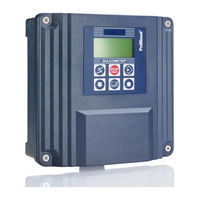
ProMinent DULCOMETER D1Cb Instructions For Assembly And Use (128 pages)
Brand:
ProMinent
| Category:
Controller
| Size: 2.56 MB
Table of Contents
Table of Contents
3
1 Introduction
6
Explanation of the Safety Information
6
Users' Qualifications
7
General Safety Information
8
Correct and Proper Use
10
ID Code
11
2 Functional Description
14
Wall Mounted/Control Panel Mounted
15
Electrical Design
16
Block Circuit Diagram
17
Galvanic Isolation
19
3 Assembly
20
Scope of Delivery
20
Installation (Wall Mounted)
21
Installation - Control Panel Mounted (Optional)
22
Wall Mounted Installation of D1Cb (Electrical)
24
Opening the Device
25
Electrical Installation (Wall Mounted)
25
Electrical Installation (Control Panel Mounted)
27
Installation of Coaxial Cable to Guard Terminal XE1
28
Cable Cross-Sections and Cable End Sleeves
29
Protective RC Circuit (Optional)
30
Terminal Wiring Diagram
31
4 Commissioning
35
Initial Commissioning
35
Selection of the Operating Language
35
Selection of the Measured Variable and Measuring Range
37
Activation Code for Extended Functions
38
Extended Functions Obtainable with the Activation Code
38
5 Operating Schematics / Display Symbols
42
Overview of Device /Operating Elements
42
Display Symbols
43
Permanent Display 1
44
Permanent Display 2
45
Permanent Display 3
45
Operating Schematics
46
Reduced / Complete Operating Menu
48
Fault Messages
49
Fault Display
49
General Settings
50
Access Code
50
6 Measured Variables and Operating Menus for Amperometric Sensors
51
Reduced / Complete Operating Menu
51
Description of All Amperometric Measured Variables
51
Reduced Operating Menu
52
Complete Operating Menu / Description of All Measured Variables
54
Calibration of All Amperometric Measured Variables
56
Calibration of the Sensor for Amperometric Measured Variables
57
Preparation for Calibration of the Sensors for Amperometric Measured Varia- Bles
57
Calibration of Zero Point and Gradient
58
Setting the Reading
60
Correction Value
60
7 Measured Variables and Operating Menus for Potentiometric Sensors
62
Reduced / Complete Operating Menu
63
Description of Ph, Redox and Fluoride Measured Variables
63
Reduced Ph / Redox / Fluoride Operating Menu
64
Complete Operating Menu/Description of Ph / Redox / Fluoride
66
Calibration of Ph, Redox and Fluoride Sensors
68
Description of the Calibration of Ph Sensors
69
Calibration of Ph Sensors. Description of the Setting Ranges
72
Calibration of Ph Sensors. Description of the Error Messages
72
Testing the Redox Sensor
73
Description of the Calibration of Fluoride Sensors
75
Temperature Correction Value for Ph and Fluoride Sensors
79
8 Measured Variables and Operating Menus for the Standard Signal General
81
Explanation of the Standard Signal General
81
Changing the Measured Variable
83
Reduced / Complete Operating Menu
83
Setting the Reading
84
Description of All Standard Signal Measured Values/Measured Variables
85
Reduced Operating Menu
86
Complete Operating Menu / Description of All Measured Variables
88
Calibrating the Standard Signal
90
Calibration of the Zero Point of the Standard Signal General
91
Two-Point Calibration of the Standard Signal General
92
9 Operating Menus Independent of Measured Variables
94
Pumps
95
Setting the Relays
96
Setting and Functional Description of the Relays
97
Setting the Limit Values
101
Setting the Control
104
Setting the Interference Variable
106
Setting the Standard Signal Output
107
General Settings
109
Setting the Measured Variable/Measuring Range
109
Sub-Functions of the "General Settings" Menu
110
10 Maintenance
113
Fuse Change on DULCOMETER ® D1Cb
113
Summary of Error Texts
114
11 Technical Data
116
DULCOMETER ® D1Cb
116
Sound Pressure Level
116
Material Data
117
Chemical Resistance
117
Dimensions and Weights
118
12 Electrical Data
119
13 Spare Parts and Accessories DULCOMETER ® D1Cb
123
14 Standards Complied with
124
15 Disposal of Used Parts
125
16 Declaration of Conformity
126
17 Index
127
Advertisement
Related Products
ProMinent DULCOMETER D1Cc
ProMinent DULCOMARIN II
ProMinent DULCOMETER D1C
ProMinent DULCOMETER Aegis-II
ProMinent DCM 2 Series
ProMinent DULCOMETER
ProMinent DULCOMETER D1CA
ProMinent diaLog DACb
ProMinent DULCOMETER Compact
ProMinent DULCOMETER diaLog DACb
ProMinent Categories
Water Pump
Controller
Measuring Instruments
Industrial Equipment
Accessories
More ProMinent Manuals
Login
Sign In
OR
Sign in with Facebook
Sign in with Google
Upload manual
Upload from disk
Upload from URL