ProMinent DULCOMETER Assembly And Operating Instructions Manual
Compact controller measurement: inductive conductivity
Hide thumbs
Also See for DULCOMETER:
- Assembly and operating instructions manual (185 pages) ,
- Installation and configuration manual (92 pages) ,
- Assembly and operating instructions manual (104 pages)
Table of Contents
Advertisement
Assembly and operating instructions
DULCOMETER
, Compact Controller
®
Measurement: Inductive conductivity
EN
A1860
Please carefully read these operating instructions before use. · Do not discard.
The operator shall be liable for any damage caused by installation or operating errors.
The latest version of the operating instructions are available on our homepage.
Part number: 984705
Version: BA DM 231 11/18 EN
Advertisement
Table of Contents

Related Manuals for ProMinent DULCOMETER


Summary of Contents for ProMinent DULCOMETER
- Page 1 Assembly and operating instructions DULCOMETER , Compact Controller ® Measurement: Inductive conductivity A1860 Please carefully read these operating instructions before use. · Do not discard. The operator shall be liable for any damage caused by installation or operating errors. The latest version of the operating instructions are available on our homepage.
- Page 2 Supplemental directives General non-discriminatory approach In order to make it easier to read, this document uses the male form in grammat‐ ical structures but with an implied neutral sense. It is aimed equally at both men and women. We kindly ask female readers for their understanding in this simplification of the text.
- Page 3 Supplemental directives Symbol Description ‘Display /GUI’ Screen elements (e.g. buttons, assignment of function keys). Presentation of software elements and/or texts. CODE...
-
Page 4: Table Of Contents
Table of contents Table of contents Identity code......................7 Introduction......................9 2.1 Measured variables..................9 Safety and responsibility..................11 3.1 Labelling of Warning Information..............11 3.2 General Safety Information................12 3.3 Intended Use....................14 3.4 User qualification..................15 Functional description................... 17 Assembly and installation.................. - Page 5 10.9 Setting and functional description of "Relay Used as a Solenoid Valve" .. 95 10.10 Alarm relay....................97 10.11 "Error logger" operating mode..............97 Maintenance......................98 11.1 Error messages ..................98 11.2 Changing the fuse, DULCOMETER ® Compact Controller....... 102 Technical data on DULCOMETER ®...
- Page 6 Table of contents Spare parts and accessories................109 Replacing spare part units ................. 110 15.1 Replacing the top part of the housing............110 15.2 Replacing the lower part of the housing (wall/tube retaining bracket)..112 15.3 Replacing the lower part of the housing (control panel installation)..115 Standards complied with and Declaration of Conformity........
-
Page 7: Identity Code
Identity code Identity code DCCa DULCOMETER ® Compact, Mounting type Spare part units Wall/pipe mounting IP 67 With fitting kit for control panel mounting IP 54 Design With ProMinent ® logo E1 Spare part unit, controller housing lower part (processor/PCB), fully... - Page 8 Identity code DCCa DULCOMETER Compact, ® English Lithuanian Spanish Latvian Italian Dutch French Polish Finish Portuguese Bulgarian Romanian Chinese Swedish Czech Slovakian Greek Slovenian Hungarian Russian Japanese Thai...
-
Page 9: Introduction
[ConI] These operating instructions describe the technical data and functions of the Symbol displayed in the controller's dis‐ [ConI] play: DULCOMETER Compact Controller, ® measured variable: Inductive conductivity Units of measurement: μS/cm, mS/cm , S/cm. The measuring range is automati‐... - Page 10 Introduction Measured variable: TDS value Measured variable: Salinity (SAL) Symbol displayed in the controller's dis‐ Symbol displayed in the controller's dis‐ [TDS] (total dissolved solids) [SAL] units: ‰ (g/kg) play: play: Unit of measurement: ppm (mg/l) Physical variable: Mass of salts in one kg of water given in PSU (practical salinity Physical variable: Total of all inorganic units).
-
Page 11: Safety And Responsibility
Safety and responsibility Safety and responsibility Labelling of Warning Infor‐ mation WARNING! Introduction Nature and source of the danger These operating instructions provide infor‐ Possible consequence: Fatal or mation on the technical data and functions very serious injuries. of the product. These operating instruc‐ Measure to be taken to avoid this tions provide detailed warning information danger. -
Page 12: General Safety Information
Safety and responsibility General Safety Information NOTICE! Nature and source of the danger WARNING! Damage to the product or its sur‐ Live parts! roundings. Possible consequence: Fatal or Measure to be taken to avoid this very serious injuries danger. – Measure: Disconnect the –... - Page 13 Safety and responsibility WARNING! NOTICE! Operating errors! Correct and proper use Possible consequence: Fatal or Damage to the product or its sur‐ very serious injuries roundings – The unit should only be oper‐ – The unit is not intended to ated by adequately qualified measure or regulate gaseous and technically expert per‐...
-
Page 14: Intended Use
Safety and responsibility Intended Use NOTICE! Correct sensor operation NOTICE! Damage to the product or its sur‐ Intended Use roundings The device is designed to measure – Correct measuring and dosing and regulate liquid media. The is only possible if the sensor is designated measured variable is working perfectly detailed on the controller and is... -
Page 15: User Qualification
Safety and responsibility User qualification WARNING! Danger of injury with inadequately qualified personnel The operator of the system / equipment is responsible for ensuring that the qualifi‐ cations are fulfilled. If inadequately qualified personnel work on the unit or loiter in the hazard zone of the unit, this could result in dangers that could cause serious injuries and material damage. - Page 16 Safety and responsibility Training Definition Electrical technician An electrical technician is able to complete work on electrical systems and recognise and avoid possible dangers independ‐ ently based on his technical training and experience as well as knowledge of pertinent standards and regulations. An electrical technician must be able to perform the tasks assigned to him independently with the assistance of drawing documentation, parts lists, terminal and circuit diagrams.
-
Page 17: Functional Description
Functional description Functional description Brief functional description Digital input to switch off the controller or to process a sample water limit The controller for the measured variable contact by remote control inductive conductivity provides the basic Temperature sensor input (Pt 100 or functions for water treatment applications. -
Page 18: Assembly And Installation
Assembly and installation Assembly and installation Scope of delivery The following parts belong to the standard scope of delivery of a DULCOMETER Com‐ ® pact Controller. Description Quantity Assembled device Cable connection set DMTa/DXMa (metr.) Operating instructions Assembly and installation NOTICE! User qualification, mechanical instal‐... - Page 19 Assembly and installation Read-off and operating posi‐ tion Install the unit in a favourable – position for reading and opera‐ tion (preferably at eye level) Mounting position Leave sufficient free space for – the cables Packaging material Dispose of packaging material in an environmentally responsible way.
-
Page 20: Assembly (Mechanical)
Assembly and installation Assembly (mechanical) The DULCOMETER ® Compact Controller is suitable for mounting on a wall, pipe or con‐ trol panel. Tab. 2: Mounting materials (contained in the scope of delivery): Description Quantity Wall/tube retaining bracket Half-round head screws 5x45 mm Washer 5.3... -
Page 21: Pipe Mounting
Fold out the wall/pipe bracket (2) light pressure at the bottom against and pull out in a downwards direc‐ the wall/pipe bracket. Then press tion upwards until the DULCOMETER ® Compact Controller audibly snaps Secure the wall/pipe bracket using into position. -
Page 22: Control Panel Mounting
Assembly and installation 5.3.3 Control panel mounting Tab. 3: Mounting kit for control panel installation of the DULCOMETER Compact Con‐ ® troller: Order number 1037273 Description Quantity Drilling template sheet 3872-4 PT screw (3.5 x 22) Profile seals Strain relief strip DF3/DF4 PT screw (3.5 x 10) - Page 23 Assembly and installation Preparing the control panel A0347 Fig. 5: The drawing is not to scale and is intended for information purposes only. Outline contour of the DULCOM‐ ETER Compact Controller housing ®...
- Page 24 Assembly and installation Mark the exact position of the DULCOMETER ® Compact Controller on the control panel using the drilling template Core hole Adhere to the 3.5 mm Ø as the core hole diameter for screwing in the fixing bolts.
- Page 25 The base for the ribbon cable is firmly soldered onto the PCB. The base cannot be removed. Open the base lock (3) to loosen the ribbon cable, see Fig. 6 Fig. 6: Loosening the ribbon cable Loosen four screws and open the DULCOMETER Compact Controller ®...
- Page 26 Assembly and installation Fig. 7: Dismantling the hinge Remove the screw (2), unclip the hinge (1) on the bottom section of the controller housing (arrows) and remove the hinge...
- Page 27 ® shown in the figure ð Ensure that the profile seal evenly surrounds the upper edge of the housing. Insert the bottom section of the DULCOMETER Compact Controller housing with ® the profile seal from behind into the cut-out and use three screws to secure it in...
- Page 28 Fig. 9: Fitting the profile seal onto the top section of the controller housing Position the profile seal (arrow) evenly into the groove in the top section of the DULCOMETER Compact Controller housing. The clips (3) must be arranged as ®...
- Page 29 Fig. 10: Push and lock the ribbon cable in its base Push and lock the ribbon cable (1) in its base Screw the top section of the controller housing onto the bottom section of the DULCOMETER Compact Controller housing ®...
-
Page 30: Installation (Electrical)
Assembly and installation Installation (electrical) WARNING! Live parts! Possible consequence: Fatal or very serious injuries – Measure: Disconnect the elec‐ trical power supply to the unit before opening the housing and secure to prevent uninten‐ tional reconnection. – Disconnect damaged or defec‐ tive devices or devices that have been tampered with and prevent unintended reconnec‐... -
Page 31: Cable Cross-Sections And Cable End Sleeves
Assembly and installation 5.4.1 Cable Cross-Sections and Cable End Sleeves Minimum cross-sec‐ Maximum cross- Stripped insulation tion section length Without cable end 0.25 mm 1.5 mm sleeve Cable end sleeve 8 - 9 mm 0.20 mm 1.0 mm without insulation Cable end sleeve 10 - 11 mm 0.20 mm... -
Page 32: Terminal Diagram / Wiring
Assembly and installation 5.4.3 Terminal diagram / wiring A1859 Fig. 11: Terminal diagram label for the Compact Controller Control signal = Control signal to the transmission coil. Measuring signal = Measuring signal from the receiver coil. Cable shield connector to pin 2 of ter‐ minal XE2 as optional connection for outer cable shield when using ICT 2, ICT 5 or CLS 52 sensors. - Page 33 Assembly and installation Terminal diagram label for the Compact Controller The transmission coil shield must be connected to pin 2 of X1. The receiver coil shield must be connected to pin 2 of X2.
- Page 34 Assembly and installation Tab. 4: Assignment of terminals to the respective sensors Terminal Sensor ICT 1 Sensor ICT 2 Sensor ICT 5 Sensor CLS52 Conductor col‐ Conductor col‐ Conductor col‐ Conductor colours ours ours ours [ye] (yellow) X1.1 Coaxial inner Brown conductor Coaxial inner con‐...
- Page 35 Assembly and installation Tab. 5: Recommended cable diameter Identification of the cable Diameter in mm Mains cable Temperature sensor cable External control cable A0348 Fig. 12: Threaded connector number...
- Page 36 Assembly and installation Tab. 6: Threaded connectors of cable openings Threade Name Ter‐ Ter‐ Pole Function Recom‐ Remark d con‐ minal minal mended nector cable Ø size Fig. 12 1 / M20 Sensor Meas‐ ① uring input Conduc‐ tivity sensor with/ without tempera‐...
- Page 37 Assembly and installation Threade Name Ter‐ Ter‐ Pole Function Recom‐ Remark d con‐ minal minal mended nector cable Ø size Fig. 12 Relay Limit 5 mm output value relay Relay Alarm 5 mm output relay ③ Pass cable through M16 single seal insert 4 / M16 Mains 90 ...
- Page 38 Assembly and installation Terminal diagram Leitfähigkeits-Sensor induktiv Temperatur (Pt100/Pt1000) Leitfähigkeits-Sensor, induktiv, (mit Pt100/Pt1000) Digital Eingang "Pause" Normsignal-Ausgang1 0/4-20mA (Schreiber,Stellglied) Extern Pumpe heben/senken Magnetventil heben/senken Grenzwertrelais,Timer,Stellglied 1 Relais (Alarm) A1950 Fig. 13: Terminal diagram...
-
Page 39: Installation (Electrical)
Assembly and installation 5.4.4 Installation (electrical) Fig. 14: Punch out threaded holes The cable must be routed in a site- Large threaded connection provided cable duct to ensure (M 20 x 1.5) strain relief Small threaded connection (M 16 x 1.5) Undo the four housing screws Punch out as many threaded con‐... -
Page 40: Switching Of Inductive Loads
Assembly and installation Switching of inductive loads C=k * I k=0,1...2 (dependent on the application). Only use capacitors of class X2. If you connect an inductive load, Units: R = Ohm; U = Volt; I = Ampere; i.e. a consumer which uses a coil C = µF (e.g. - Page 41 Assembly and installation Typical AC current application with an inductive load: 1) Load (e.g. alpha motor-driven pump) 2) RC-protective circuit – Typical RC protective circuit at 230 V AC: [0.22µF/X2] – Capacitor [100 Ohm / 1 W] – Resistance (metal oxide (pulse resistant)) 3) Relay contact (XR1, XR2, XR3)
-
Page 42: Sensor Connector
Sensor connector Sensor connector User qualification, sensor connector: trained and qualified personnel Ä Chapter 3.4 ‘User qualification’ on page 15 Shielded sensor cable All conductivity sensors connected to the controller require shielded sensor cables. Many conductivity sensors have total shielding. The conductivity sensors ICT 1 have an internally connected total shielding. - Page 43 Sensor connector A1417 Fig. 17: Measuring principle Receiver and signal processing Hole Oscillator Sensor head Cable Sample water Receiver coil Induced current Transmission coil...
- Page 44 Sensor connector Sensor Connector Cell con‐ T-correc‐ Max. Measuring Measuring stant tion ele‐ temp. range κ range κ ment Cell con‐ (°C) stant (Unit) (Unit) (1/cm) ICT 1 Fixed Pt100 70 °C 1000 8.5 cm ± cable, 7 m μS/cm mS/cm ICT 2 Fixed...
-
Page 45: Commissioning
Commissioning Commissioning Setting the control during User qualification: trained user, see Ä Chapter 3.4 ‘User qualification’ commissioning on page 15 NOTICE! WARNING! Reset to factory settings Sensor run-in periods When switching over the metering This can result in dangerous incor‐ direction, all actuators in the con‐... -
Page 46: Selecting The Sensor Type
Commissioning Selecting the sensor type Use of fixed-cable ProMinent sensors Press and use the keys [INPUT] to move the cursor to the Entering the cable length menu item and confirm the selec‐ tion with The precise entry of the cable... - Page 47 Commissioning Using external sensors Press twice to return to the con‐ tinuous display. Press and use the keys [INPUT] to move the cursor to the menu item and confirm the selec‐ tion with Use the keys to move the [SENSOR] menu item cursor to the and confirm with Use the...
-
Page 48: Temperature Compensation And Reference Temperature
Commissioning Temperature compensation and reference temperature Adjust the temperature compensation and reference temperature for correct display of [ConI] and resistance [RES] . the inductive conductivity [TDS] and [SAL] . Non-adjustable values are specified by the controller for the display of Tab. - Page 49 Commissioning The inductive conductivity measured at the fluid temperature is converted to the [TREF] . reference temperature Changing the reference tem‐ perature The temperature coefficient [TCOEFF] has to be recalibrated if the reference temperature [TREF] is changed. Adjustable process for temperature com‐ pensation [off] –...
-
Page 50: Operating Diagram
Operating diagram Operating diagram Overview of equipment/Operating elements Ä Chapter 3.4 ‘User qualification’ on page 15 User qualification: instructed user, see A0291 Fig. 18: Overview of equipment/Operating elements Function Description 1st respective meas‐ Affix the measured variable label here ured variable 2. -
Page 51: Entering Values
Operating diagram Function Description 6. DOWN key To decrease a displayed numerical value and move down in the operating menu 7. MENU key To access the controller's operating menu 8. STOP/START key Starts and stops the control and metering function 9. -
Page 52: Adjusting Display Contrast
Operating diagram Adjusting display contrast If the DULCOMETER ® Compact Controller ‘continuous display’ , you can set is set to the contrast of the LCD-display. By pressing the key you can adjust the LCD display contrast so it is darker. By... -
Page 53: Continuous Display
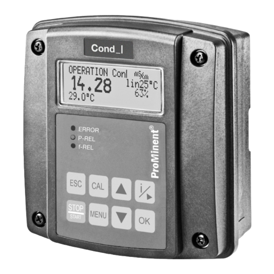
Operating diagram Continuous display ConI µS A1861 Fig. 20: Continuous display Measured variable (switch using Temperature (correction variable) [ESC] ): the following are possible: Measured value (actual value) [ConI] , [RES] , [TDS] and [SAL] Operating status Reference temperature or temperature compensation Control variable Possible error text: for example... -
Page 54: Information Display
Operating diagram Information display The most important parameters for each first-level menu item are displayed in the infor‐ mation display. to access the information display from the continuous display. Pressing again calls up the next information display. Pressing calls up the continuous display again. ⒾLIMITS ⒾCONTROL dosing ↓... -
Page 55: Password
Operating diagram Password Access to the setting menu can be restricted by a password. The controller is delivered ‘5000’ . The controller is set up with the pre-set password ‘5000’ so with the password that access is possible to all menus. ≡MENU INPUT OUTPUT... -
Page 56: Operating Menus
Operating menus Operating menus Ä Chapter 3.4 ‘User qualification’ on page 15 User qualification: instructed user STOP ℂ CAL ▶CELLCONST A1864 Fig. 23: Overview of the first level menu. [CAL] the con‐ Calibrating ductivity sensor Correct sensor operation The following calibration functions are Correct measurement and –... - Page 57 Operating menus Incorrect calibration An error message ‘ERR’ appears if the result of the calibration lies outside the specified tolerance limits. In this case, the current cali‐ bration is not applied. Check the prerequisites for calibra‐ tion and clear the error. Then repeat calibration.
-
Page 58: Calibration Of The Cell Constant
Operating menus 9.1.1 Calibration of the cell constant CELLCONST TCOEFF ZERO CAL CELLCONST TCoeffCAL 1.90%/°C CAL CELLCONST µS COND= 43,2 /cm @25°C CAL_T= 155.0 °C CAL=CONTINUE CAL CELLCONST@25°C µS COND= 043,975 CAL CELLCONST CELLC 1.0000cm CAL=ACCEPT A1865 Fig. 24: Calibration of the cell constant... - Page 59 Operating menus Calibration compared to a calibration solution [CELLCONST] and con‐ Press and use the key to move the cursor to firm with Enter the temperature coefficient of the calibration solution. The temperature coefficient of the calibration solution is specified on the storage tank for the calibration solution.
- Page 60 Operating menus Calibration compared with a reference Calibration by entering a precisely known measurement (e.g. manual measuring cell constant device) Press and use the [INPUT] to move the cursor to Temperature coefficient of the Confirm with measuring solution Use the key to move the [CELLC] .
-
Page 61: Calibration Of The Temperature Coefficient
Operating menus Tab. 8: Sensor status Display Meaning Status [OK] In order Cell constant = 0.005 / 99.9 [WRN] Warning none [ERR] Error Cell constant < 0.005 or cell constant > 100 9.1.2 Calibration of the temperature coefficient Conductivity sensors with temperature element You can only calibrate the temperature coefficient with conductivity sensors with a temperature element, because it is impossible to calculate the temperature coeffi‐... - Page 62 Operating menus CELLCONST TCOEFF CAL TEMPCOEFF CAL_T1= 22.0 °C CAL=CONTINUE CAL TEMPCOEFF CHANGE TEMP T2 > 32.0 °C T2 < 12.0 °C CAL TEMPCOEFF WAIT T2 > 32.0 °C T2 < 12.0 °C CAL TEMPCOEFF STABLE ? CAL_T2= 43.0 °C CAL=CONTINUE III.
- Page 63 Operating menus Calibrate at the first calibration temperature calibration temperature; this calibration temperature should be close to the selected reference temperature. [CAL] to accept the first calibration point. At the same time the temperature Press ranges for the second temperature value are given. [CHANGE TEMP] , now immerse the sensor in the same liquid with Important note: the second calibration temperature (minimum temperature difference ±...
-
Page 64: Calibrating The Zero Point
Operating menus 9.1.3 Calibrating the zero point Dry the sensor and keep it free from electromagnetic fields If the zero point of the sensor is to be calibrated, it is essential that the sensor is removed, rinsed and dried before calibration. No electromagnetic fields may influ‐ ence the sensor as these electromagnetic fields could distort calibration. - Page 65 Operating menus Calibrating the zero point Press , remove the sensor from the application in which it is fitted. Rinse the sensor with clean water and dry it. [ZERO] and confirm with Use the key to move the cursor to Hold the sensor in the air.
-
Page 66: Setting Limit Values [Limits]
Operating menus [LIMITS] Setting limit values ≡MENU LIMITS MENU CONTROL INPUT ※LIMITS ※LIMITS LIMIT↑= 0.020 LIMIT↑= 00.020 LIMIT↓= 0.010 HYST.= ※LIMITS ※LIMITS LIMIT↑= 0.020 LIMIT↓= 00.010 LIMIT↓= 0.010 HYST.= ※LIMITS ※LIMITS LIMIT↓= 0.020 05 % HYST. = LIMIT↑= 0.010 HYST.= ※LIMITS ※LIMITS TLIMIT↑= 80.0 °C... - Page 67 Operating menus Setting Possible values Display Starting Increment Lower value Upper value Remark value [LIMIT ↑] 0.02 S/cm 0,001 0.000 2.000 S/cm Upper limit value uS/cm [LIMIT ↓] 0.01mS/cm 0,001 0.000 2.000 S/cm Lower limit value uS/cm [HYST. ] 20 % Hysteresis of limit values [TLIMIT ↑]...
- Page 68 Operating menus [HYST.] Hysteresis = If the value has fallen below a limit value, then the limit value criteria are reset when the measured value has reached the value of the limit value plus hysteresis. If the value has fallen below a limit value, then the limit value criteria are reset when the measured value has reached the value of the limit value minus hysteresis.
-
Page 69: Setting The Control [Control]
Operating menus [CONTROL] Setting the control ≡MENU LIMITS MENU CONTROL INPUT ※CONTROL ※CONTROL PUMP: dosing↓ PUMP: dosing↓ SET= 1.000 dosing↑ TYPE: ※CONTROL ※CONTROL PUMP: dosing↓ SET= 01.000 SET= 1.000 TYPE: ※CONTROL ※CONTROL PUMP: dosing↓ TYPE: SET= 1.000 manual TYPE: ※CONTROL ※CONTROL TYPE: ↳Xp=... - Page 70 Operating menus Setting Possible values Starting Increment Lower value Upper Remark value value [PUMP] [dosing [dosing ↓] One-way control ↑] direction [dosing ↑] [SET] 0,001 0.000 uS/cm 2.000 S/cm mS/cm [TYPE] Controller type Manual [↳Xp] 0,001 0.000 uS/cm 2.000 S/cm P-proportion of mS/cm control variable [↳Ti]...
- Page 71 Operating menus Setting Possible values Starting Increment Lower value Upper Remark value value [CHECK‐ 0 min 1 min 0 min 999 min Control checkout TIME] time 0 minutes = off [BOOT 30 s 9999 s Control delay DELAY] period after the start of the meas‐...
-
Page 72: Setting Inputs [Input]
Operating menus [INPUT] Setting inputs ≡MENU ※INPUT ※INPUT LIMITS SENSOR: ICT 1 MENU SENSOR: ICT 1 CONTROL ↳CELLC: 8.5000cm INPUT ↳LEN= 7.00m ※INPUT ※INPUT ※INPUT ※INPUT norm.open ↳POL: SENSOR: ICT1 ↳ALARM: ↳CELLC: 08.5000cm ↳DELAY OFF= ↳CELLC: 8.5000cm ↳ALARM: ↳LEN= 7.00m ※INPUT ℂ... - Page 73 Operating menus Setting Possible values Display Starting Increment Lower Upper Remark value value value [SENSOR] ICT 1 Sensor type [↳ CELLC] 8.5 cm 0.001 0.006 Cell constant 15 cm [↳ LEN] 0.01 200 m Cable length [↳ 0.95 Ω 0.01 0 Ω...
- Page 74 Operating menus Setting Possible values Display Starting Increment Lower Upper Remark value value value [↳ 77.0 °F 32.0 °F 302.0 °F Manual correction VALUE] value °F [CON‐ [pause] [pause] Configuration of digital TACT] contact input [ hold] [↳ POL] [norm.open] [norm.open] Polarity of the contact input [norm.closed]...
- Page 75 Operating menus [ZK] . The geometry of the sensor is fully described by the cell constant The geometrical conditions of the sensor surroundings are described by the installation [FINSTALL] . The installation factor [FINSTALL] does not need to be considered if factor [a] >...
- Page 76 Operating menus A1849 Fig. 32: Distance from wall [a]...
-
Page 77: Setting The [Manual] Sensor In The [Input] Menu
Operating menus [MANUAL] sensor in the [INPUT] menu Setting the ≡MENU ※INPUT ※INPUT LIMITS SENSOR: MANUAL MENU SENSOR: MANUAL CONTROL ↳MIN= 100.000µS/cm INPUT ↳MAX= 2.00 S/cm ※INPUT ※INPUT SENSOR: MANUAL ↳MIN= 00.000µS/cm ↳MIN= 100.000µS/cm ↳MAX= 2.00 S/cm ℂ CHECK ZERO ※INPUT SENSOR: ↳MIN= 100.000µS/cm... - Page 78 Operating menus [MANUAL] process Setting a sensor in the Setting Possible values Display Starting Increment Lower Upper Remark value value value [SENSOR] [MANUAL] Sensor type [↳ MIN] 100,000 For limit value settings µS/cm when changing the sensor. [↳ MAX] 2.00 S/cm For limit value settings when changing the sensor.
- Page 79 Operating menus [CELLCONST] and con‐ Press and use the key to move the cursor to firm with Enter the temperature coefficient of the calibration solution. The temperature coefficient of the calibration solution is specified on the storage tank for the calibration solution. Confirm with Now dip the sensor into the calibration solution and gently move the sensor.
- Page 80 Operating menus Confirm with Now dip the sensor into the calibration solution and gently move the sensor. Wait until the conductivity and temperature measured value has stabilised. Press ð The conductivity value measured is displayed. Now use the keys to enter the conductivity value measured, in accord‐ ance with the conductivity value specified on the calibration solution.
-
Page 81: Setting Outputs [Output]
Operating menus [OUTPUT] Setting outputs ≡MENU INPUT MENU OUTPUT DEVICE ※OUTPUT ※OUTPUT alarm P-REL: alarm unused P-REL: f-REL : dosing dosing ↳ limit PUMPMAX=180/min ※OUTPUT ※OUTPUT P-REL: alarm f-REL: dosing f-REL : dosing unused ↳ PUMPMAX=180/min ※OUTPUT ※OUTPUT ※OUTPUT ※OUTPUT ↳0/4mA= 0.010 P-REL: alarm... - Page 82 Operating menus Setting Possible values Starting Increment Lower value Upper Remark value value [P-REL] [alarm] [alarm] Alarm relay (Power [unused] relay) [dosing] PWM relay P ulse W idth M o dulation) [limit] Limit value relay [↳PERIOD] 60 s 30 s 6000 s Cycle time of PWM control...
- Page 83 Operating menus Setting Possible values Starting Increment Lower value Upper Remark value value [↳PUMPMA 180 RPM 1 RPM 500 RPM Maximum stroke rate of the low power relay (fre‐ quency relay) [mA OUT] [meas va] l [off] [off] = off (Issued vari‐...
- Page 84 Operating menus Setting Possible values Starting Increment Lower value Upper Remark value value [↳20 mA] 212.0 °F 0.1 °F 32.0 °F 302.0 °F Temp. value assigned 20 [↳20 mA] 100 % 10 % / 100 % / Control value - 10 % - 100 % assigned 20 (0/4 mA is fixed...
-
Page 85: Setting The [Device]
Operating menus [DEVICE] Setting the ≡MENU INPUT OUTPUT MENU DEVICE ※DEVICE ※DEVICE PASSWORD: **** NEW PASSW. 5000 RESTART DEVICE 5000=FREE FACTORY RESET ※DEVICE RESTART!!! PASSWORD: **** RESTART DEVICE FACTORY RESET ※DEVICE FACTORY RESET!!!! PASSWORD: **** PASSWORD: RESTART DEVICE 5000 FACTORY RESET ※DEVICE ※DEVICE RESTART DEVICE... - Page 86 Operating menus Setting Possible values Starting Increment Lower value Upper value Remark value [FACTORY [no] [yes] [yes] = [no] = no All the con‐ RESET...] [FACTORY [FACTORY troller's [no] RESET!] RESET!] parameters are reset to factory set‐ tings. [CAL This function is used to calibrate the amplifier measuring chain in the DEVICE...] [ERR] is displayed, depending on the controller.
-
Page 87: Control Parameters And Functions
Control and all other outputs are on page 15 frozen New faults are detected, however 10.1 they have no effect on the alarm relay DULCOMETER Com‐ ® or the mA output. However the effect pact Controller function of already existing faults (e.g. fault... - Page 88 Control parameters and functions ‘CAL’ (calibration) is started while ‘ OPERATION’ functional state (normal mode) is active, then the ‘ PAUSE/HOLD’ is functional state ‘CAL’ (calibration) com‐ ignored until pletes. However STOP/START is possible at any time An alarm can be acknowledged or removed as follows: By clearing all faults by pressing the key and the...
-
Page 89: Stop/Start] Key
Control parameters and functions [STOP/START] key 10.2 Control is started / stopped by pressing . You can press regardless of the menu currently displayed. However the [STOP] state is only shown in the contin‐ uous display. STOP A1872 Fig. 36: [STOP] mode. -
Page 90: Priming [Prime]
Control parameters and functions [PRIME] 10.3 Priming PRIME↑↑↑ STOP A1873 Fig. 37: Priming, e.g. to vent a pump [STOP] and [OPERATION] modes, you can While the continuous display is visible, in [PRIME] by simultaneously pressing start the priming function [P-REL] is actuated at Depending on the configuration of the controller, the output relay [f-REL] is actuated at 80 % of "PUMPMAX"... -
Page 91: Hysteresis Limit Value
Control parameters and functions 10.4 Hysteresis limit value Measured value Upper limit value "Hysteresis“ "Hysteresis" Lower limit value Limit value transgression A0009_GB Fig. 38: Hysteresis [LIMIT↑] Upper limit value = [LIMIT↓] Lower limit value = [LIMIT↑] and [LIMIT↓] is the valid measuring range. The range between [hysteresis] , which is set as a % to the respective [LIMIT] value. -
Page 92: Temperature Correction Variable
Control parameters and functions 10.5 Temperature correction variable Available temperature A temperature reading for the con‐ ductivity always has to be avail‐ able, either by a temperature measurement or a manual tem‐ perature setpoint. The correction variable compensates for the effect of the temperature of the medium on the measured value. -
Page 93: Checkout Time For Measured Variable And Correction Variable
TLIMITERR Checkout time of the correction variable If upon the expiry of the checkout time, the valid measuring range is not reached, then the DULCOMETER ® Compact Controller exhibits the following behaviour: LIMIT ERR: The control is switched off. An error current is emitted, provided the output is configured as a measured variable output TLIMITERR: The control is switched off. -
Page 94: Power Relay "P-Rel" As Limit Value Relay
Control parameters and functions ‘LIMIT’ can be used to set The parameter a limit for the control variable. If the con‐ trol variable exceeds this limit value, the CHECKTIME fault is triggered (checkout time of the control has elapsed). The con‐ trol is switched to basic load and a fault current output. -
Page 95: Setting And Functional Description Of "Relay Used As A Solenoid Valve
Control parameters and functions 10.9 Setting and functional description of "Relay Used as a Solenoid Valve" Cycle Solenoid min. time Actuating valve variable: 80 % = 0.80 Cycle Cycle Actuating variable: 50 % = 0.50 Cycle A0025_GB Fig. 39: Solenoid valve (= P-REL: dosing) [MIN ON] min. - Page 96 Fig. 40: Theoretical switching time < min. time [MIN ON] min. time [PERIOD] (in seconds) Cycle The DULCOMETER ® Compact Controller does not switch on for a certain number of ‘min. time’ . Then it cycles until the sum of the theoretical switching times exceeds switches for the duration of this total time.
-
Page 97: Alarm Relay
Control parameters and functions 10.10 Alarm relay ‘OPERATION’ The alarm relay triggers in (normal mode) if an error occurs which ‘ERROR’ and not has been defined as ‘WARNING’ . just as ‘ALARM’ in the con‐ The error message tinuous display is marked with a ✱ (star) and can be acknowledged with the key. -
Page 98: Maintenance
Maintenance Maintenance User qualification: trained user, see Ä Chapter 3.4 ‘User qualification’ Error detection following on page 15 device start The controller is maintenance- free. The majority of errors are only dis‐ played with a 10-second delay fol‐ lowing the start-up of the unit. 11.1 Error messages User qualification for diagnosis:... - Page 99 Maintenance Tab. 10: Error messages [Error ] Error mes‐ Brief description of fault sage [Warning] [RANGE↓] The measured variable falls below the measuring range [RANGE↑] The main measured variable exceeds the measuring range Temperature value falls below the measuring range RANGE↓] Temperature value exceeds the measuring range RANGE↑]...
- Page 100 Maintenance [Error ] Error mes‐ Brief description of fault sage [Warning] [INPUT↑] Conductivity signal exceeds the input measuring range [TEST?] Check the sensor's connection. Cable breakage? No sample water?
- Page 101 Maintenance Tab. 11: Response of the unit due to the error messages Error message Control mA meas‐ mA correc‐ Limit Suppressed mode uring output tion output value during user relay calibration [RANGE↧] Basic load Error current [RANGE↥] Basic load Error current [T RANGE↧] Basic load Error current...
-
Page 102: Changing The Fuse, Dulcometer ® Compact Controller
Danger from electrical voltage controller housing top section to the left Possible consequence: Fatal or very serious injuries. Remove the PCB cover – The DULCOMETER ® Compact Remove the micro-fuse using a Controller does not have a suitable tool mains switch Fit the micro-fuse using a suitable –... -
Page 103: Technical Data On Dulcometer ® Compact Controller
Technical data on DULCOMETER Compact Controller ® Technical data on DULCOMETER Compact Controller ® 12.1 Permissible ambient conditions Degree of protection (IP) The controller fulfils the IP 67 degree of protection requirements (wall/pipe mounting) or IP 54 (control panel mounting). This degree of protection is only ach‐... -
Page 104: Material Data
Technical data on DULCOMETER Compact Controller ® 12.3 Material data Part Material Housing lower and upper section PC-GF10 Bracket rear side housing bottom section PPE-GF20 Operating film Polyester PET membrane Seal Expanded PUR Cover screws Stainless steel A2 Profile seal (control panel mounting) Silicone 12.4... -
Page 105: Electrical Data
Electrical data Electrical data Mains connection Nominal voltage range 100 ... 230 VAC ± 10 % Frequency 50 ... 60 Hz Power consumption 50 ... 100 mA Main and auxiliary inputs, display and measuring ranges Tab. 14: Main input: Variable Display range Specific inductive conductivity 0.1 …... - Page 106 Electrical data Variable Display range TDS (total dissolved solids) 0 … 2000 ppm (mg/l) SAL (salinity) 0.0 … 70.0 ‰ (g/kg) Maximum cable length of the sensor cable 20 metres Tab. 15: Auxiliary input: Variable Display range Temperature Pt100/Pt1000 (automatic detec‐ Cable length 10 m: - 20 °C …...
- Page 107 Electrical data The mains connection is isolated from other switching parts by reinforced insulation. The unit has no mains switch; a fuse is fitted. Output relay (P-relay) Load capacity of switching contacts 5 A; no inductive loads Outputs galvanically isolated from other switching parts by reinforced insulation. Digital input Open circuit voltage 22 V DC max.
- Page 108 Electrical data The mA output is galvanically isolated from all other connections (500 V) Pump control (f-relay) Max. switching voltage: 50 V (protective low voltage) Max. switching current: 50 mA Max. residual current (open): 10 mA Max. resistance (closed): 60 W Max.
-
Page 109: Spare Parts And Accessories
Spare parts and accessories Spare parts and accessories Spare parts Part number Fine fuse 5x20 T 0.315 A 732404 Wall/tube retaining bracket 1002502 Guard terminal top part (knurled nut) 733389 Measured variable labels 1002503 DMT fixing strap 1002498 Cable connection set DMTa/DXMa (metric) 1022312 Controller housing lower part (processor/PCB), fully assembled Identity code DCCA_E_E1 ... -
Page 110: Replacing Spare Part Units
Fig. 42: Loosening the ribbon cable Undo four screws and open the DULCOMETER ® Compact Con‐ troller Open the right and left lock (3) - Page 111 With control panel installation: Posi‐ tion the profile seal (arrow) evenly into the groove in the top part of the DULCOMETER Compact Con‐ ® troller housing. Arrange the flaps (3) as shown in the figure...
-
Page 112: Replacing The Lower Part Of The Housing (Wall/Tube Retaining Bracket)
(3) to loosen the tings. ribbon cable, see Fig. 42 Fig. 47: Loosening the ribbon cable Undo four screws and open the DULCOMETER Compact Con‐ ® A0273 troller Open the right and left lock (3) (arrows) on the base and pull the ribbon cable (1) out of the base. - Page 113 Replacing spare part units Fig. 49: Punching out the threaded holes Large threaded connection (M 20 x 1.5) Small threaded connection (M 16 x 1.5) Punch out as many threaded holes Fig. 48: Dismantling the hinge on the bottom of the lower part of Remove the screw (2), unclip the the controller housing as required hinge (1) on the lower part of the...
- Page 114 Replacing spare part units Fig. 51: Suspend and secure the DULCOMETER Compact Controller ® Suspend the DULCOMETER ® Compact Controller at the top (1) in the wall/tube retaining bracket and push using light pressure at the bottom (2) against the wall/pipe retaining bracket.
-
Page 115: Replacing The Lower Part Of The Housing (Control Panel Installation)
Replacing the lower part Fig. 52: Loosen the ribbon cable from the base of the housing (control panel installation) Undo four screws and open the DULCOMETER ® Compact Con‐ troller Complete commissioning of Open the right and left lock on the... - Page 116 Fig. 55: Punching out the threaded holes Check the profile seal (arrow), then position the profile seal evenly into the groove in the top part of the DULCOMETER ® Compact Con‐ troller housing. Arrange the flaps (3) Large threaded connection as shown in the figure (M 20 x 1.5)
- Page 117 They are not needed for control panel installation Position the profile seal (arrow) Position the profile seal evenly evenly into the groove in the top around the top edge of the lower part of the DULCOMETER ® Com‐ part of the DULCOMETER ® Com‐...
-
Page 118: Standards Complied With And Declaration Of Conformity
Standards complied with and Declaration of Conformity Standards complied with and Declaration of Conformity The Declaration of Conformity for the con‐ troller is available to download on our homepage. EN 61010-1 Safety requirements for elec‐ trical equipment for measurement, control and laboratory use –... -
Page 119: Disposal Of Used Parts
Material Safety Data Sheet for your feed chemical. A current Declaration of Decontamination In accordance with the European Directive is available to download on the ProMinent 2012/19/EU on waste electrical and elec‐ website. tronic equipment, this device features the symbol showing a waste bin with a line through it. -
Page 120: Index
Index Index Drill holes ....21 Drilling template ....23 Accessories . - Page 121 ......17 Original Prominent cable ..32 Question: What control direction is Overview of equipment .
- Page 122 Index Question: Which sensors can I con‐ Standards complied with ..118 nect to the controller? ... . 42 Strain relief ....25, 39 Question: Which standards are com‐...
- Page 124 ProMinent GmbH Im Schuhmachergewann 5 - 11 69123 Heidelberg Telephone: +49 6221 842-0 Fax: +49 6221 842-419 Email: info@prominent.com Internet: www.prominent.com 984705, 3, en_GB © 2018...
Need help?
Do you have a question about the DULCOMETER and is the answer not in the manual?
Questions and answers