Sign In
Upload
Manuals
Brands
ProMinent Manuals
Controller
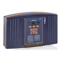
DULCOMETER Aegis-II
ProMinent DULCOMETER Aegis-II Manuals
Manuals and User Guides for ProMinent DULCOMETER Aegis-II. We have
1
ProMinent DULCOMETER Aegis-II manual available for free PDF download: Assembly And Operating Instructions Manual
ProMinent DULCOMETER Aegis-II Assembly And Operating Instructions Manual (121 pages)
Cooling Tower and Boiler Controller
Brand:
ProMinent
| Category:
Controller
| Size: 7 MB
Table of Contents
Table of Contents
2
1 Operating Concept
6
The Front Panel
6
Functions of the Keys
7
Changing the Operating Language
7
Keypad Lock
7
2 Navigating the [Menu] Display
8
Input/Output Status [Momentary Display]
9
Modifying the 'Home' Screen
9
3 Identcode
10
4 Safety and Responsibility
15
Explanation of the Safety Information
15
General Safety Notes
16
Intended Use
17
Warranty Guide
17
Users' Qualifications
17
Training
18
5 Functional Description
19
6 Mounting and Installation
20
Scope of Supply
21
Mechanical Installation
21
Wall Mounting
21
Electrical Installation
22
Specification of the Cable Grips and Conduit Entries
23
Sensor Seals and Termination Procedure
24
Parking the Hood
25
General Layout and Terminal Diagrams
25
Power in and Relay Output Termination
32
Overview
32
Wiring Relays R1 and R2
33
Wiring Relays R1 and R2 for a Motor Operated Valve
33
Wiring Relays R3 - R5 Using On-Board Power
33
Wiring Relays R3 - R5 Using an External Power Source
34
Wiring Motor Operated Valves (MOV) to Relays R3 - R5
34
Connecting a Power Cord
35
Frequency Output Termination
35
Using a Universal Control Cable on a Pulse Output Relay
35
Wiring Sensors to the Controller
35
Inputs on the Main Board
36
The G Input (4-20Ma)
36
Temperature Input H
37
Digital Inputs O through V
37
Namur Inputs U and V
37
Sensor Driver Cards
38
Dual Serial Input Card (Ctfs-LPR-DP)
39
Dual CT (Conductivity/Temperature)
40
Conductivity and Conductivity/Temperature Sensors
40
Temperature Sensors
40
Dual Ph-ORP-Temp Driver
42
Attaching the Ph/Orp Coax Cable
44
Orp/Ph, Temperature and Ma Input Card
45
Dual 4-20Ma Input Driver
46
Connection of Amperometric Sensors
48
Little Dipper II Connection - 4-20Ma
49
Pyxis Connection - 4-20Ma
50
Echopod Level Sensor Connection - 4-20Ma
51
Dual 4-20Ma Output Driver
52
7 Communication
53
Diagram of the Communication Modules
53
8 Commissioning
54
Switch-On Behavior During Commissioning
54
Defining Metering and Control Processes
54
9 Programming the Inputs
54
Analog and Digital Inputs
55
Enable an Analog or Digital Input
55
Enable a CTFS [Conductivity, Temp, Flow, Serial] Sensor
56
Changing a Descriptor
57
Selecting an Analog Sensor Type
57
Selecting the Sensor Type
57
Analog Sensor Cleaning and Calibration
59
General Remarks
59
Sensor Commissioning
59
Calibrating and Checking Probes
59
Calibrating Ph Probes
59
Checking Redox/Orp Probes
59
Cleaning and Servicing Probes
60
Storage
60
Service Life
60
Calibration Notes
61
General Sensor Calibration
61
Calibrating an Amperometric Sensor
63
Analog Sensor Alarms
64
Analog Alarm Configuration
64
Analog Sensor Diagnostics
65
Ph-ORP Driver Card Diagnostics
66
CT (Conductivity, Boiler Cond., Condensate and Temperature) Driver Card Diagnostics
66
The 4-20Ma Input Driver Card Diagnostics
66
The 4-20Ma Output Driver Card Diagnostics
67
Serial Sensors (Ctfs, LPR, DP) Driver Card Diagnostics
67
Configuring Digital Inputs
68
Configure a Digital Input as a Water Meter
68
Link a Water Meter to a Relay (Applies to All Relays )
69
Fail to Feed (Feed Verification)
70
Disable an Analog or Digital Input
71
Changing or Unlinking an Analog Input Tied to an Output Relay
72
Changing or Unlinking Analog Inputs Tied to a 4-20Ma Output
73
Changing or Unlinking a Digital Input Tied to a Digital Output
73
Changing or Unlinking a Digital Input Tied to a 4-20Ma Output
74
Phantom Inputs
74
10 Programming the Control Outputs (Relay and 4-20Ma)
74
Frequency/Pulse Outputs
75
Determine if a Relay Is Enabled
75
Enable and Configure a Relay
75
Naming the Output
76
Configuring a Blowdown Relay
77
Configuring a Feed Relay
77
Feed Based on a Water Meter
78
Feed Based on a Sensor
78
Feed Based on Bleed And/Or Feed
79
Bleed then Feed
79
Bleed and Feed
79
Feed Based on Percent Time & Base Feed
80
Feed Based on a Sensor with Event Control
80
Set up a Relay Using the Feed Mode with an Oxidant Sensor; ORP or any 4-20Ma Input
80
Choosing a Cycle
80
Configuring an Event-Other Relay
81
Schedules, Prebleeding, Lockout and with a Sensor
81
Prebleed/Lockout
82
Add, Remove, Edit Events
83
Adding Events
83
Interlocks
85
Setting/Removing Interlocks
85
Blocks
86
Control Action (on Decreases/On Increases Sensor)
86
Special Control Functions
87
Timed Cycling
88
Time Modulate
88
PID Control
90
Math Functions
91
Digital Input Math
91
Analog Input Math
91
Relay Outputs 1 - 9 Math
91
Analog Outputs (4-20Ma) Math
91
Boiler Blowdown
92
Continuous Boiler Blowdown
92
Captured Sample Blowdown
92
Varying Cycles
95
How to Setup a Relay as an Alarm Output
97
Relay a an Alarm Output:
97
Prime (Force On) a Relay
98
Sensor Wash
98
M Aoutputs
98
How to Assign 4-20Ma Output to Control Decrease (E.g Acid Feed)
99
How to Assign 4-20Ma Output to Control Increase (E.g Caustic Feed)
100
How to Assign 4-20Ma Output to Measured Value (Application: Feedback to PLC/DCS)
101
How to Set 4-20Ma Output to Manual Mode
102
Linking a 4-20Ma Input with a 4-20Ma Output
102
Calibration of a 4-20Ma Output
103
11 System Menu
104
Communications
104
How to Change the IP Address
104
Web Interface Wi-Fi
105
System Setup
105
Site Name/Controller Name
105
Sunday=Day 1
105
Keypad Passwords On/Off
106
Metric Units
106
Number of Systems
106
Alarm on Stops
106
System Restart and Factory Reset
106
Language
106
Time and Date
106
Set Sensor Type
107
Passwords - Login/Logout
107
Enable I/O
107
How to Change a Password
107
Activity Log
108
Diagnostics
109
Configurations
109
12 Controller Technical Data
110
Fuse Specification
110
Controller Specifications
110
Sensor Specifications
111
13 Using the Usb Port
112
Capturing Data
112
Save or Load the Program Configuration
113
Saving to the USB
113
Loading from the USB
113
Saving To/From Flash
113
Firmware Upgrade Using Usb
114
Remote HMI (Browser) Firmware Update
115
E-Mail Reports and Alarms
116
E-Mail Types
116
ALARM: Sent Once When an Alarm First Occurs
116
STATUS: Sent @ Noon Every Day (12:00). Verifies that the Controller Is Running & on the LAN
116
DAILY: Sent @ Midnight (23:59) Every Day. Verifies that the Controller Is Running & on the LAN
116
14 Spare Parts and Accessories
117
Figure
118
15 Maintenance
120
16 Certifications
120
17 Necessary Formalities
121
Disposal of Used Parts
121
Gency Pprovals
121
Advertisement
Advertisement
Related Products
ProMinent DULCOMETER
ProMinent DULCOMETER Compact
ProMinent DULCOMETER diaLog DACb
ProMinent DULCOMETER diaLog X
ProMinent DULCOMARIN II
ProMinent DULCOMETER D1Cb
ProMinent DULCOMETER D1C
ProMinent DCM 2 Series
ProMinent DULCOMETER D1CA
ProMinent diaLog DACb
ProMinent Categories
Water Pump
Controller
Measuring Instruments
Industrial Equipment
Accessories
More ProMinent Manuals
Login
Sign In
OR
Sign in with Facebook
Sign in with Google
Upload manual
Upload from disk
Upload from URL