Sony MVS-8000 User Manual
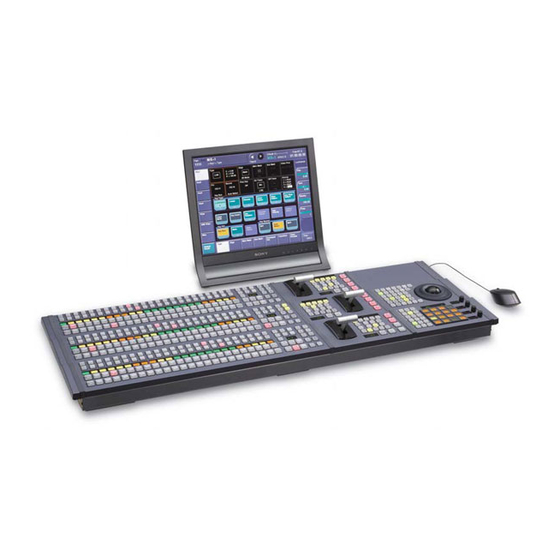
With ccp-8000 series center control panel
Hide thumbs
Also See for MVS-8000:
- User manual (1364 pages) ,
- System setup manual (134 pages) ,
- Operation manual (22 pages)
Table of Contents

Related Manuals for Sony MVS-8000


Summary of Contents for Sony MVS-8000
- Page 1 Multi Format Switcher System MVS-8000/8000SF System (With CCP-8000 Series Center Control Panel) User’s Guide [English] Volume 2 User’s Guide 2nd Edition (Revised 1) Volume 2 2nd Edition (Revised 1) 3-206-017-12 (1) English...
- Page 2 MVS-8000/8000SF System (With CCP-8000 Series Center Control Panel) User’s Guide Multi Format Switcher System [English] Volume 2 2nd Edition (Revised 1) Software Version 7.20 and Later...
- Page 3 NOTICE TO USERS © 2001 Sony Corporation. All rights reserved. This manual or the software described herein, in whole or in part, may not be reproduced, translated or reduced to any machine readable form without prior written approval from Sony Corporation.
-
Page 4: Table Of Contents
Table of Contents Chapter 11 DME Operations Three-Dimensional Transformation Operations........15 Basic Operations..................15 Three-Dimensional Parameter Display ..........19 Entering Three-Dimensional Parameter Values........20 Graphics Display ...................21 Canceling Virtual Images ..............23 DME Special Effect Operations ..............24 Border Settings ..................24 Crop Settings ..................28 Beveled Edge Settings................31 Key Border Settings ................33 Art Edge Settings...................34 Flex Shadow Settings ................44... - Page 5 Motion Decay Settings ................119 Keyframe Strobe Settings..............121 Wind Settings ..................123 Spotlighting Settings ................126 Background Settings................136 Separate Sides Settings................137 Shaped Video Settings.................138 Invert Settings..................140 Key Density Settings ................141 Key Source Selection ................141 Interpolation Settings ................142 Global Effect Operations ................145 Combiner Settings ................145 Brick Settings ..................150 Shadow Settings ..................154 Chapter 12 External Devices...
- Page 6 Creating and Editing Keyframes ..............207 Creation ....................207 Insertion....................208 Modification ..................208 Deletion ....................212 Movement....................213 Copying ....................214 Pause....................214 Keyframe Loop (Repeated Execution of a Specified Range) .....215 Undoing an Edit Operation..............218 Duration Mode Setting ................218 Transition Mode Settings for User Programmable DME....219 Time Settings....................220 Setting the Keyframe Duration............220 Setting the Effect Duration..............221...
- Page 7 Snapshot Operations in the Menus ............260 Selecting a Region or Reference Region in a Menu......260 Setting Snapshot Attributes ..............260 Snapshot Status Display ..............263 Setting Key Snapshot Attributes ............265 Creating and Saving a Master Snapshot..........265 Snapshot Register Editing ..............266 Displaying a List of Snapshot Registers for Editing ......267 Operations in the Misc >Snapshot menu..........267 Chapter 15 Utility/Shotbox Utility Execution ..................272...
- Page 8 Cross-Point Settings (Xpt Assign Menu) ..........342 Auxiliary Bus Control Block Settings (Aux Assign Menu)....351 Setting Button Assignments (Prefs/Utility Menu) ......356 Interfacing With External Devices (Device Interface Menu)....367 Operation Settings (Operation Menu) ..........374 Screen Saver and Other Settings (Maintenance Menu).......381 Setup Relating to Switcher Processor............384 Settings for Switcher Configuration (Config Menu)......384 Signal Input Settings (Input Menu) .............390 Signal Output Settings (Output Menu)..........398...
- Page 9 Displaying the Individual File Operation Menus ........466 Viewing Detailed File Information .............466 Selecting Regions ................468 Selecting a Device for Operations............468 Saving Files ..................469 Loading Files ..................470 Copying Files ..................472 Renaming Files..................473 Deleting Files ..................475 Converting Between Frame Memory Clips and Extended Clips ..476 File Batch Operations.................479 Displaying the Batch Operation Menu ..........479 Batch Saving Files................479...
- Page 10 Saving a Macro..................516 Macro Editing Using Menus..............517 Macro Register Editing ...............517 Online Editing of Macro Events............517 Offline Editing of Macro Events ............523 Macro Attachment Assigning ..............529 Setting and Canceling a Macro Attachment........529 Displaying the Macro Attachment List ..........533 Executing a Macro by Macro Attachment...........534 Menu Macros ....................536 Recalling a Menu Macro Register and Executing a Menu Macro ..536 Recalling a Menu Macro Register............536...
- Page 11 Shape Patterns ..................574 Functional Differences With Models of DME..........575 Menu Tree ....................578 Recalling Menus..................578 M/E-1 to M/E-3 Menus ...............578 PGM/PST Menu ..................581 Frame Memory Menu................583 Color Bkgd Menu ................584 AUX/MON Menu................584 CCR Menu...................585 Copy/Swap Menu ................586 Misc Menu...................586 Status Menu ..................587 DME Menu..................588 Global Effect Menu ................589 Device Menu ..................589...
- Page 12 Error Messages Appearing in a Message Box........624 Error Messages Shown in the Error Information Menu ......637 Data Saved by [Setup Define] and [Initial Status Define].......641 Menu Operations Not Recorded in a Menu Macro.........651 Index ......................652 Table of Contents...
- Page 13 Table of Contents...
- Page 14 Chapter 11 DME Operations Three-Dimensional Transformation Operations ........15 Basic Operations ..................15 Three-Dimensional Parameter Display ..........19 Entering Three-Dimensional Parameter Values ........20 Graphics Display .................21 Canceling Virtual Images ..............23 DME Special Effect Operations ..............24 Border Settings ..................24 Crop Settings ..................28 Beveled Edge Settings .................31 Key Border Settings ................33 Art Edge Settings .................34 Flex Shadow Settings ................44...
- Page 15 Nonlinear Effect Settings ..............81 Lighting Settings ................110 Trail Settings ..................115 Motion Decay Settings ..............119 Keyframe Strobe Settings ..............121 Wind Settings ..................123 Spotlighting Settings .................126 Background Settings ................136 Separate Sides Settings ..............137 Shaped Video Settings ...............138 Invert Settings ..................140 Key Density Settings .................141 Key Source Selection ................141 Interpolation Settings ................142 Global Effect Operations .................145...
-
Page 16: Three-Dimensional Transformation Operations
Three-Dimensional Transformation Operations Use the device control block to carry out three-dimensional DME transformations. For details of three-dimensional DME coordinate space, see “Three- Dimensional Transformations” in Chapter 1 (Volume 1). Basic Operations This section explains how to use the device control block (trackball) to carry out three-dimensional transformations. - Page 17 Transforming an image in three-dimensional coordinate space With the region selection buttons, select the target channel of the operation. You can press several of the buttons simultaneously to select several channels. In this case, the button that you pressed first lights in green, while buttons pressed subsequently light in amber.
- Page 18 To change the aspect ratio of the image: With the [SRC] button selected in step 2, press the [ASP PERS] button, turning it on. You can change the aspect ratio independently on the x- and y-axes with the trackball, and change it simultaneously on both the x- and y- axes with the Z-ring.
- Page 19 image, z-axis parameters increase as you rotate counterclockwise, and decrease as you rotate clockwise. To reduce the rate of change of the parameters (fine mode) Carry out the trackball or Z-ring operations while holding down the [SRC] or [TRGT] button. To restrict the change in the transformation to a specific axis, press the [X], [Y], or [Z] button, tuning it on.
-
Page 20: Three-Dimensional Parameter Display
Three-Dimensional Parameter Display You can check the values of the three-dimensional parameters in the DME menu. Displaying the three-dimensional parameters in the DME menu In the menu control block, select the top menu selection button [DME]. The DME menu appears. The status area shows the three-dimensional parameters currently controlled by the device control block. -
Page 21: Entering Three-Dimensional Parameter Values
Example three-dimensional parameter details Entering Three-Dimensional Parameter Values In addition to setting three-dimensional parameter values with the trackball and Z-ring, you can enter them directly from the numeric keypad control block. Entering three-dimensional parameter values In the device control block, press the [X], [Y], or [Z] button, turning it on. The numeric keypad control block enters a mode in which you can enter parameters for the selected axis. -
Page 22: Graphics Display
To enter difference values You can enter difference values by pressing the [+/–] button, entering the difference from the current value, and pressing the [TRIM] button to confirm. The [+/–] button toggles between “+” (plus) and “–” (minus) each time it is pressed. - Page 23 The DME menu appears. Select VF6 ‘Input/Output’ and HF4 ‘Graphic.’ The Graphic menu appears. Turn [Graphic] on. The system enters graphics display mode, enabling graphics to be displayed in the monitor screen. Turn on the buttons of the graphics you want to show. To show axes: Turn [Axis] on.
-
Page 24: Canceling Virtual Images
Graphics are displayed on the device connected to the monitor output connector. Note Output to the Monitor Out connector is not supported on the MVE-8000. When the MKE-8021A is installed in the MVE-8000A to provide an SDI interface or when the MVE-9000 is used, it is possible to output graphics to the Monitor Out connector. -
Page 25: Dme Special Effect Operations
DME Special Effect Operations You can use DME to add a variety of special effects. The following types of DME special effects are available. For details of DME special effects, see “DME Special Effects” in Chapter 1 (Volume 1). • Edge effects: Border, Crop, Beveled Edge, Key Border, Art Edge, Flex Shadow •... - Page 26 For an illustrative figure and other information, see “DME Special Effects” in Chapter 1 (Volume 1). Adding a border In the DME menu, select VF1 ‘Edge’ and HF1 ‘Border/Crop.’ The Border/Crop menu appears. Press [Border], turning it on. The Border effect is enabled. You can adjust the border width parameters with the knobs.
- Page 27 Parameter group [1/2] Knob Parameter Adjustment Setting values Border width on top and bottom Top value shown sides Border width on all sides Left value shown Density Border density 0.00 to 100.00 Parameter group [2/2] Knob Parameter Adjustment Setting values Border width on top side –4.50 to +4.50 Left...
- Page 28 Parameter group [1/2] Knob Parameter Adjustment Setting values Border width on all sides Left value shown Density Border density 0.00 to 100.00 Parameter group [2/2] Knob Parameter Adjustment Setting values Border width on top side –18.00 to +18.00 Left Border width on left side –32.00 to +32.00 Right Border width on right side...
-
Page 29: Crop Settings
Softening the border edges Press [Border Soft], turning it on, and set the following parameters. Knob Parameter Adjustment Setting values Soft Softness of inner side of border 0.00 to 100.00 Crop Settings This effect crops the image. For an illustrative figure and other information, see “DME Special Effects” in Chapter 1 (Volume 1). - Page 30 Parameter group [2/2] Knob Parameter Adjustment Setting values Right Crop position on right side –4.00 to +4.00 Bottom Crop position on bottom side –3.00 to +3.00 • SD format, 16:9 mode Parameter group [1/2] Knob Parameter Adjustment Setting values Crop positions on left and right Left value shown sides Crop positions on top and...
- Page 31 • HD format, 16:9 mode Parameter group [1/2] Knob Parameter Adjustment Setting values Crop positions on left and right Left value shown sides Crop positions on top and Top value shown bottom sides Crop positions on all sides Left value shown Parameter group [2/2] Knob Parameter...
-
Page 32: Beveled Edge Settings
vertically around that axis of symmetry. The order of effect application is Crop > Invert. Invert –> Crop: Set an axis of symmetry at the center of the input video, and invert only the desired area of video horizontally and vertically around that axis of symmetry. - Page 33 Knob Parameter Adjustment Setting values Simultaneously adjust width of left 0.00 to 4.00 and right edges Simultaneously adjust width of top 0.00 to 2.25 and bottom edges Simultaneously adjust width of all Value of H shown four edges • HD format, 4:3 mode Knob Parameter Adjustment...
-
Page 34: Key Border Settings
• To set the colors for each edge (Top, Left, Right, Bottom, All) Knob Parameter Adjustment Setting values Luminance Luminance 0.00 to 100.00 Saturation Saturation 0.00 to 100.00 359.99 to 0.00 a) For the All adjustment, the value for Left is shown. To soften the inside of the edges and the boundaries between adjacent edges, turn on [Edge Soft], and adjust the following parameters. -
Page 35: Art Edge Settings
This enables key borders, and you can now use the knobs to adjust the parameters. Note The key border function and Glow function (see page 75) cannot be turned on at the same time. Only the one most recently turned on is effective. Set the following parameters. - Page 36 The Art Edge menu appears. Press [Art Edge], turning it on. This enables art edges, and you can now use the knobs to adjust the parameters. Note The Defocus, Blur, Key Border, and Glow effects cannot be applied to the Art Edge sections.
- Page 37 Parameter group [1/2] Knob Parameter Adjustment Setting values Simultaneously adjust width of all Value of Left shown four edges Density Density of edges 0.00 to 100.00 Parameter group [2/2] Knob Parameter Adjustment Setting values Width of top edge 0.00 to 4.50 Left Width of left edge 0.00 to 8.00...
- Page 38 Parameter group [1/2] Knob Parameter Adjustment Setting values Simultaneously adjust width of all Value of Left shown four edges Density Density of edges 0.00 to 100.00 Parameter group [2/2] Knob Parameter Adjustment Setting values Width of top edge 0.00 to 18.00 Left Width of left edge 0.00 to 32.00...
- Page 39 • HD format, 4:3 mode Knob Parameter Adjustment Setting values Position of top edge –9.00 to +9.00 Left Position of left edge –12.00 to +12.00 Right Position of right edge –12.00 to +12.00 Bottom Position of bottom edge –9.00 to +9.00 Adjust the position of all four Value of H shown edges...
- Page 40 Knob Parameter Adjustment Setting values Outer H Simultaneously adjust softness of 0.00 to 100.00 left and right outer edges Outer V Simultaneously adjust softness of 0.00 to 100.00 top and bottom outer edges Simultaneously adjust softness of Value of Outer H all inner and outer edges.
- Page 41 The valid ranges of the parameter values depend on the combination of signal format (SD/HD) and aspect ratio (4:3/16:9) selected in the system, as follows. • SD format, 4:3 mode Knob Parameter Adjustment Setting values Position of gradation border in –8.00 to +8.00 horizontal direction Position of gradation border in...
- Page 42 Knob Parameter Adjustment Setting values Soft Softness of gradation border 0.00 to 100.00 region Rainbow Gradation parameters The valid ranges of the parameter values depend on the combination of signal format (SD/HD) and aspect ratio (4:3/16:9) selected in the system, as follows.
- Page 43 Knob Parameter Adjustment Setting values Position of gradation border in –18.00 to +18.00 vertical direction RBW Soft Softness of rainbow border region 0.00 to 100.00 GRD Soft Softness of gradation border 0.00 to 100.00 region When Gradation Matte or Rainbow Matte is selected, set modifiers as required.
- Page 44 Adjust the following parameters. • Color 1 settings Knob Parameter Adjustment Setting values Luminance Luminance 0.00 to 100.00 Saturation Saturation 0.00 to 100.00 359.99 to 0.00 • Color 2 settings Note Color 2 cannot be set when [Flat Color] is selected in the <Art Edge Source>...
-
Page 45: Flex Shadow Settings
Color 1 Hue setting range Hue Offset setting range Offset -180 -360 Color 2 -540 Rounding art edge corners Press [Round Corner], turning it on. The art edge corners on the inner and outer sides are rounded. Note This function is available only when [Soft] is on. Flex Shadow Settings This effect applies a shadow to the picture using only one channel. - Page 46 Applying a flex shadow In the DME menu, select VF1 ‘Edge’ and HF5 ‘Flex Shadow.’ The Flex Shadow menu appears. Press [Flex Shadow], turning it on. This enables flex shadows, and you can now use the knobs to adjust the parameters.
- Page 47 a) The Soft parameter is valid only when [Internal] is selected in the <Flex Shadow Source> group. • HD format, 4:3 mode Knob Parameter Adjustment Setting values Move shadow horizontally –24.00 to +24.00 Move shadow vertically –18.00 to +18.00 (see Size All Enlarge or shrink horizontally and Value of Size H...
- Page 48 Knob Parameter Adjustment Setting values 359.99 to 0.00 Adjusting the size of the flex shadow In the Flex Shadow menu, press [Size], turning it on. Set the following parameters. Knob Parameter Adjustment Setting values Size H Enlarge or shrink horizontally 0.00 to 2.00 Size V Enlarge or shrink vertically...
- Page 49 • HD format, 4:3 mode Knob Parameter Adjustment Setting values Axis Loc H Move the shadow center axis –24.00 to +24.00 horizontally Axis Loc V Move the shadow center axis –18.00 to +18.00 vertically • HD format, 16:9 mode Knob Parameter Adjustment Setting values...
- Page 50 Adjust the following parameters. Knob Parameter Adjustment Setting values Skew H Skew horizontally –100.00 to +100.00 Skew V Skew vertically –100.00 to +100.00 Adding perspective to the flex shadow In the Flex Shadow menu, press [Perspective], turning it on. Adjust the following parameters. Knob Parameter Adjustment...
- Page 51 Picture Before inversion Flex shadow After inversion After inversion Before inversion When H is enabled When V is enabled Setting a combine shadow In the Flex Shadow menu, press [Combine Shadow], turning it on. Adjust the following parameter. Knob Parameter Adjustment Setting values Density...
-
Page 52: Wipe Crop Settings
Press [Flex Shadow], turning it on. In the <Flex Shadow> group, select [External]. Turn [Axis Loc] on and use knob 2 to set the Axis Loc V parameter so that the center of the flex shadow deformation is at the bottom of the picture. (For HD format and 16: 9 mode: Axis Loc V = –9.00) The following steps will be easier if you display the flex shadow axis graphic by pressing [Flex Shadow Axis] in the Graphic menu. - Page 53 • In the <Shaped Video> group of the Video/Key menu, when [Output] is off, unless you set [Bkgd] in the HF1 ‘Bkgd’ menu to on, the wipe crop effect will not be visible. Applying the wipe crop effect To select the pattern In the DME menu, select VF1 ‘Edge’...
- Page 54 Note When pattern number 304 is selected, the effect of settings in the <Edge> group varies with the Size setting. • For HD format Knob Parameter Adjustment Setting values Horizontal position –24.00 to +24.00 –32.00 to +32.00 Vertical position –18.00 to +18.00 Size Pattern size 0.00 to 100.00...
- Page 55 • When Angle is selected Knob Parameter Adjustment Setting values Angle Angle of pattern rotation –8.00 to +8.00 a) –1.00 represents a whole turn counterclockwise, and +1.00 represents a whole turn clockwise. 0.00 is the original state. • When Speed is selected Knob Parameter Adjustment...
- Page 56 Knob Parameter Adjustment Setting values Invert Type Replication layout 1 to 4 a) See the following figure Modifying the wipe crop pattern edge You can apply a border to the wipe crop pattern, or soften the boundary. In the <Edge> group of the Wipe Crop menu, select one of the following. Border: border Soft: soft edge Soft Border: soft border...
-
Page 57: Color Mix Settings
Selecting the signal or color to be inserted in the wipe crop border When you are applying a border or soft border to the wipe crop, you can select the signal or color to be inserted in the border. In the <Border Fill> group of the Wipe Crop menu, select one of the following. - Page 58 The Mix Pattern Select menu appears. Press any of the displayed patterns (standard wipe patterns 1 to 24) to select it. In this state, you can adjust the pattern size and border softness with the knobs. (For details of the parameters, see the next item.) To set the pattern size and position In the Color Mix menu, press [Position/Size].
-
Page 59: Defocus Settings
Adjusting the color 1 and color 2 In the Color Mix menu, to adjust color 1 press [Color1], and to adjust color 2 press [Color2]. Set the following parameters. Knob Parameter Adjustment Setting values Luminance Luminance 0.00 to 100.00 Saturation Saturation 0.00 to 100.00 359.99 to 0.00... - Page 60 In the <Defocus Mode> group, select the signal to which to apply the defocus effect. Video/Key: Video signal and key signal Video: Video signal only Key: Key signal only Note “Key” can be selected only when the MVE-8000A/MVE-9000 is connected through an SDI interface. Set the parameters.
-
Page 61: Blur Settings
Parameter group [2/2] Knob Parameter Adjustment Settings values Key H Horizontal defocusing of key 0.00 to 100.00 signal Key V Vertical defocusing of key signal 0.00 to 100.00 • When Video is selected Knob Parameter Adjustment Setting values Horizontal defocusing of video 0.00 to 100.00 signal Vertical defocusing of video... - Page 62 The Defocus/Blur menu appears. Press [Blur], turning it on. The Blur effect is enabled. You can adjust the blurring of video and key signals with the knobs. Note On the MVE-8000A, the Glow and Blur effects cannot be enabled at the same time.
-
Page 63: Multi Move Settings
Parameter group [2/2] Knob Parameter Adjustment Settings values Video H Horizontal defocusing of video 0.00 to 100.00 signal Video V Vertical defocusing of video 0.00 to 100.00 signal Key H Horizontal defocusing of key 0.00 to 100.00 signal Key V Vertical defocusing of key signal 0.00 to 100.00 •... - Page 64 For an illustrative figure and other information, see “DME Special Effects” in Chapter 1 (Volume 1). Applying the Multi Move effect In the DME menu, select VF2 ‘Video Modify’ and HF2 ‘Multi Move.’ The Multi Move menu appears. Press [Multi Move], turning it on. The Multi Move effect is enabled.
-
Page 65: Sepia Settings
Knob Parameter Adjustment Setting values Center Y y-value of shrinking center point –9.00 to +9.00 Size Shrinking ratio 0.00 to 100.00 Aspect Aspect ratio of shrunken images –100.00 to +100.00 a) Specify minus values to stretch the image in the vertical direction, and plus values to stretch the image in the horizontal direction. -
Page 66: Mono Settings
To set the color of the sepia image, press [Sepia Color], turning it on, and adjust the parameters. Knob Parameter Adjustment Setting values Luminance Luminance 0.00 to 100.00 Saturation Saturation 0.00 to 100.00 359.99 to 0.00 Masking the Sepia effect with a selected pattern Press [Mask] to display the Mask menu, and set the pattern type and modifiers. -
Page 67: Posterization And Solarization Settings
Posterization and Solarization Settings The Posterization and Solarization effects both give a painting-like effect by coarsening the gradations of the image. The Posterization effect coarsens luminance gradations, and the Solarization effect coarsens chroma gradations. Applying the Posterization or Solarization effect In the DME menu, select VF2 ‘Video Modify’... -
Page 68: Contrast Settings
Applying the Nega effect In the DME menu, select VF2 ‘Video Modify’ and HF3 ‘Color Modify.’ The Color Modify menu appears. Press [Nega Y] or [Nega C], turning it on, or press both buttons, turning them on. Nega Y: Reverse the luminance. Nega C: Reverse the chroma. -
Page 69: Mosaic Settings
Video output level Video output level Gain Offset Video input Video input Clip level level Clip, Gain, Offset Masking the Contrast effect with a selected pattern Press [Mask] to display the Mask menu, and set the pattern type and modifiers. For details, see “Mask Settings”... -
Page 70: Sketch Settings
Knob Parameter Adjustment Setting values Aspect Aspect ratio of tiles –100.00 to +100.00 a) Specify minus values to stretch the tiles in the vertical direction, and plus values to stretch the tiles in the horizontal direction. Masking the Mosaic effect with a selected pattern Press [Mask] to display the Mask menu, and set the pattern type and modifiers. - Page 71 Set the following parameters, according to the method selected in step 3. • When Sketch is selected Knob Parameter Adjustment Setting values Mix amount for Sketch video and 0.00 to 100.00 input video Clip Reference level for outline –100.00 to +100.00 extraction Gain Image gain for outline extraction...
- Page 72 a) 100.00 gives an image completely transformed by the Sketch effect. 0.00 is the original input image. • When Sharp is selected Knob Parameter Adjustment Setting values Simultaneously adjust the left and 0.00 to 100.00 right resolution Simultaneously adjust the top and 0.00 to 100.00 bottom resolution Simultaneously adjust the...
-
Page 73: Metal Settings
To invert white and black in the extracted video, or to invert the outlines and the sections other than the outlines, press [Nega], turning it on. Masking the Sketch effect with a selected pattern Press [Mask] to display the Mask menu and set the type of pattern and modifiers. -
Page 74: Dim And Fade Settings
In the <Metal Mode> group, select the type of metallic gloss. Gold: Give a gold gloss to the input video. Silver: Give a silver gloss to the input video. Rainbow: Give a rainbow color gloss to the input video. Variable: Give a metallic gloss to the input video in any color by adjusting the following parameters. -
Page 75: Glow Settings
Set the following parameters. Knob Parameter Adjustment Setting values Start Point where dimming starts (dim –100.00 to +100.00 start point) Gain Degree of dimming 0.00 to 100.00 Press [Flat Color] and set the parameters for the color of the depths of the picture. - Page 76 Applying the Glow effect In the DME menu, select VF7 ‘Enhanced Video Modify’ and HF4 ‘Glow.’ The Glow menu appears. Press [Glow], turning it on. This enables the Glow effect. Notes • On the MVE-9000, the key border function and Glow function cannot be turned on at the same time.
-
Page 77: Mask Settings
Note The Mask function is not supported on the MVE-8000. Mask Settings This effect masks part of the picture, so that special effects are applied only inside a selected pattern. For a sample illustration and other information, see “Digital Multi Effects (DME)”... - Page 78 Knob Parameter Adjustment Setting values Size Size of mask 0.00 to 100.00 Soft Softness of mask 0.00 to 100.00 Pattern Pattern number 21, 24, 304 a) This setting value is not supported on the MVE-8000A. • SD format, 16:9 mode Knob Parameter Adjustment...
- Page 79 • When turning [Aspect] on and adjusting the pattern aspect ratio Knob Parameter Adjustment Setting values Aspect Aspect ratio –100.00 to +100.00 a) When a minus value is specified, the picture is extended in the vertical direction. When a plus value is specified, the picture is extended in the horizontal direction. •...
-
Page 80: Freeze Settings
Image 2: State with [Effect Gp1] only set to On Portion 2 has ‘Mono’ Portion 1 has both masked, and ‘Defocus’ ‘Mono’ and ‘Defocus’ only applied. applied. In the state corresponding to image 2, if you switch [Effect Gp2] to On, then the mask should be applied to portion 2 only, but in fact the border or beveled edge is also masked. - Page 81 Applying the Hard Freeze effect In the <Freeze Timing> group, select the signal freeze timing. Frame: Freeze one frame of signal. Field 1: Freeze the first field of signal. Note During the execution of a freeze with the MVE-8000, you cannot change the freeze timing.
-
Page 82: Nonlinear Effect Settings
Applying the Film effect Note When 720P signal format is used, the Film mode cannot be selected. In the <Freeze> group, press [Film], turning it on. The Film freeze is enabled. You can adjust the ratio of frame advance. Set the parameter. Knob Parameter Adjustment... - Page 83 Name Effect Flying Bar Divides the image into bars which peel off in two blocks page 95 as they move. Blind Divides the image into bars or wedges, with blocks page 95 rotating like the slats of venetian blinds. Split Splits the image upper and lower, left and right.
- Page 84 Wave settings The Wave effect produces a wave-like effect in the image. Note When the signal format is 720P/59.94 or 720P/50, the Wave function cannot be used on the MVE-8000. To apply the Wave effect With the Wave menu displayed, use the following procedure. In the <Mode>...
- Page 85 Parameter group [1/2] Knob Parameter Adjustment Setting values Amp H Amplitude of waves in horizontal 0.00 to 100.00 direction Freq H Frequency of waves in horizontal 0.00 to 100.00 direction Horizontal direction in which to Offset H –16.00 to +16.00 offset wave phase and amount of –64.00 to +64.00 movement...
- Page 86 Offset To stop the waves Press [Lock], turning it on. With each press, the waves alternately stop and start moving again. To select the waveform Press [Form] and set the following parameters. • When H&V mode is selected Knob Parameter Adjustment Setting values Form H...
- Page 87 Knob Parameter Adjustment Setting values Random H Degree of randomness in 0.00 to 100.00 horizontal waveform modulation Random V Degree of randomness in vertical 0.00 to 100.00 waveform modulation Random All Degree of randomness in both Random H value vertical and horizontal directions shown •...
- Page 88 Size Envelope Offset To smooth the range envelope when the wave range is limited Press [Range Envelope], turning it on. Set the following parameters. • When H&V mode is selected Knob Parameter Adjustment Setting values Envelope H Smoothness of envelope in 0.00 to 100.00 horizontal direction Envelope V...
- Page 89 The items displayed in the Mosaic Glass menu and the functions of the knobs are the same as for the Wave menu. For more information about how to make settings, see “Wave settings” (page 83). Flag settings Applies an effect like a flag waving in the wind. To apply the Flag effect Display the Flag menu.
- Page 90 To stop the waves Press [Lock], turning it on. With each press, the waves alternately stop and start moving again. To select the waveform Press [Form] and set the following parameters. Knob Parameter Adjustment Setting values Form H Waveform in horizontal direction 1 to 6 Form V Waveform in vertical direction...
- Page 91 Set the following parameters, depending on the selected modulation mode. • When Radial mode is selected Knob Parameter Adjustment Setting values Amp R Ripple amplitude along radius 0.00 to 100.00 Freq R Ripple frequency along radius 0.00 to 100.00 Direction along radius in which Offset R –8.000 to +8.000 to offset ripple phase and...
- Page 92 Parameter group [2/2] Knob Parameter Adjustment Setting values Amp A Ripple amplitude along periphery 0.00 to 100.00 Freq A Ripple frequency along periphery 0.00 to 100.00 Direction along periphery in –8.000 to +8.000 Offset A which to offset ripple phase and amount of movement Ripple direction along periphery –100.00 to +100.00...
- Page 93 To set the ripple center point Press [Position], turning it on. Set the following parameters, depending on the selected modulation mode. • When Shape is selected Knob Parameter Adjustment Setting values Ripple center point in –5.000 to +5.000 horizontal direction –20.000 to +20.000 Ripple center point in vertical –3.000 to +3.000...
- Page 94 • When Angular mode is selected Knob Parameter Adjustment Setting values Size A Amount of ripple modulation along 0.00 to 100.00 periphery Offset A Center of modulation range along –8.000 to +8.000 periphery • When Both mode is selected Knob Parameter Adjustment Setting values...
-
Page 95: Broken Glass Settings
To make transition settings, press [Transition] and set the following parameters. Knob Parameter Adjustment Setting values Transition Degree of transition 0.000 to 100.000 Random Degree of randomness in distance 0.000 to 100.000 moved by each block Spiral Amount of movement toward –1.000 to +1.000 periphery accompanying transition To set the partition method, press [Partition] and set the following... - Page 96 To apply the Broken Glass effect Display the Broken Glass menu. The functions of the knobs in the Broken Glass menu are the same as those of the Rings menu, with the exception of [Direction]. For details about operation, see “Rings settings” (page 93). To fix the direction in which shards scatter Press [Direction], turning it on.
- Page 97 To make transition settings, press [Transition] and set the following parameters. Knob Parameter Adjustment Setting values Rotation Number of rotations of the blocks –8.000 to +8.000 Perspective Degree of randomness in distance 0.000 to 100.000 moved by each block To set the partition method, press [Partition] and set the following parameters.
- Page 98 Split settings The Split effect splits the image upper and lower, left and right. To apply the Split effect With the Split menu displayed, use the following procedure. In the <Mode> group, select the split method. Single: Leave gaps between splits. Double: Fill gaps between splits with the same image.
- Page 99 Parameter group [1/2] Knob Parameter Adjustment Setting values Random H Degree of randomness in distance 0.00 to 100.00 moved by blocks in horizontal direction Skew H Degree of skew in horizontal direction 0.00 to 100.00 Width H Horizontal width of partition 0.00 to 100.00 Angle Angle of partition line...
- Page 100 Top to Bottom: Reflect top side on bottom. Bottom to Top: Reflect bottom side on top. Top to Left to Right Bottom SONY SO S To set the position of the border between original and reflection Press [Position]. Set the following parameters.
- Page 101 Knob Parameter Adjustment Setting values Offset V Amount of vertical offset of image –4.000 to +4.000 with mirrors fixed –16.000 to +16.000 Angle Mirror angle –8.000 to +8.000 a) Setting for SD 4:3, SD 16:9 b) Setting for HD 4:3, HD 16:9 To set the center position of original image Press [Position], turning it on.
- Page 102 To set the reflection position Press [Position], turning it on. Set the following parameters. Knob Parameter Adjustment Setting values Horizontal reflection position 0.000 to 4.000 0.000 to 16.000 Vertical reflection position 0.000 to 3.000 0.000 to 12.000 a) Setting for SD 4:3, SD 16:9 b) Setting for HD 4:3, HD 16:9 To cyclically repeat part of the original and its reflection Press [Cyclic], turning it on.
-
Page 103: Circle Settings
• When Bar is selected Knob Parameter Adjustment Setting values Magnify H Magnification ratio –100.00 to +100.00 Curve H Curve ratio –100.00 to +100.00 Size H Size 0.00 to 100.00 Angle Slant angle –8.000 to +8.000 • When Cross is selected Parameter group [1/2] Knob Parameter... - Page 104 To apply the Circle effect With the Circle menu displayed, set the following parameters. Knob Parameter Adjustment Setting values Radius Size of circle 0.00 to 100.00 To make the axis of modulation vertical Press [Mod V], turning it on. The axis of modulation when converting to the circle becomes vertical. Panorama settings The Panorama effect curves the upper and lower edges of the image to emphasize the sense of perspective.
- Page 105 Knob Parameter Adjustment Setting values Radius Radius of turn part 0.00 to 100.00 Offset Amount of turn –100.00 to +100.00 Angle Angle of turn –0.250 to +0.000 –0.250 to +0.250 –0.500 to +0.000 –8.000 to +8.000 a) When split mode is H&V b) When split mode is H c) When split mode is V d) When split mode is off...
-
Page 106: Cylinder Settings
The knobs in the Roll menu have the same functions as those in the Page Turn menu. For details about operation, see “Page Turn settings” (page 103). Cylinder settings The Cylinder effect winds the whole image onto a cylinder. To apply the Cylinder effect With the Cylinder menu displayed, set the following parameters. - Page 107 • Heart • Ellipse Set the following parameters. • When Circle was selected in step 1 Knob Parameter Adjustment Setting values Transition Degree of transition 0.00 to 100.00 Curve Degree to which image periphery 0.00 to 100.00 expands Spiral Degree of curvature of transition –100.00 to +100.00 path •...
- Page 108 Knob Parameter Adjustment Setting values Center point in vertical direction –4.000 to +4.000 –16.000 to +16.000 a) Setting for SD 4:3, SD 16:9 b) Setting for HD 4:3, HD 16:9 Swirl settings The Swirl effect swirls the image. To apply the Swirl effect With the Swirl menu displayed, set the following parameters.
- Page 109 Melt settings The Melt effect melts the image away from a specified part. To apply the Melt effect With the Melt menu displayed, use the following procedure. In the <Direction> group, select the direction in which the image melts away. Up: Melting occurs upward.
-
Page 110: Character Trail Settings
Knob Parameter Adjustment Setting values Form Waveform 1 to 8 a) 1 (SINE): Sine wave 2 (PARABOLA): Parabola wave 3 (TRIANGLE): Triangular wave 4 (RECTANGLE): Rectangular wave 5 (CIRCLE): Circular wave 6 (CUBIC): Cubic wave 7 (MELT1): Melting wave 1 8 (MELT2): Melting wave 2 To make the melting part stardust Press [Pixel], turning it on. -
Page 111: Lighting Settings
Knob Parameter Adjustment Setting values Density Degree to which image disappears 0.00 to 100.00 Random Trail type and amount of stardust 0.00 to 100.00 Lighting Settings This effect provides the effect of light striking the image. The following lighting patterns are available: •... - Page 112 Note The Total Ambient parameter is not supported on the MVE-8000/8000A. • When Bar is selected Knob Parameter Adjustment Setting values Light Intensity of light in highlight area 0.00 to 100.00 Ambient Intensity of light in ambient area 0.00 to 100.00 Total Ambient Brightness of whole image 0.00 to 100.00 a) You can make the Lighting effect more effective by adjusting [Total Ambient] to lower the...
- Page 113 Setting the bar shape of the highlight area When you select [Bar] or [Preset] in step 3 of “Applying the Lighting effect” (page 110), use the following procedure to set the shape of the bar. Turn [Light Modify] on. Adjust the following parameters. Knob Parameter Adjustment...
- Page 114 Knob Parameter Adjustment Setting values Luminance Luminance 0.00 to 100.00 Saturation Saturation 0.00 to 100.00 359.99 to 0.00 Setting the bar shape of the shade area When you select [Preset] in step 3 of “Applying the Lighting effect” (see page 110), use the following procedure to set the bar shape of the shade area.
- Page 115 Note The bar mode of the highlight area is not supported on the MVE-8000/8000A. Select the mode in the <Bar Light Mode> group. Normal: Emphasizes the bar highlight area. Specular: An effect like light striking a surface with metallic reflections. Mat: An effect like light striking paper, cloth, or another diffusively reflective surface.
-
Page 116: Trail Settings
With no selection made in With a selection made in the <Bar Light Mode> the <Bar Light Mode> group group Width Bar Light Diffuse Light Diffuse Light Bar Light Offset = 0 Trail Settings This effect recursively freezes the input video at regular intervals so that a trail of afterimages is created. - Page 117 Applying the Trail effect In the DME menu, select VF5 ‘Light/Trail’ and HF2 ‘Trail.’ The Trail menu appears. Press [Trail], turning it on. The Trail effect is enabled. You can adjust the parameters with the knobs. Set the parameters. Knob Parameter Adjustment Setting values...
- Page 118 Freeze Video: Use freeze images of the input video as source of the trail. Flat Color: Use a flat color matte as source of the trail. You can set the following parameters with the knobs. Knob Parameter Adjustment Setting values Luminance Luminance 0.00 to 100.00...
- Page 119 Signal formats: 1080PsF/30, 1080PsF/29.97, 1080PsF/25, 1080PsF/24, 1080PsF/23.976, 720P/59.94, 720P/50 Defocusing the afterimage portion (Defocus) Note The function to defocus the trail afterimage portion is not supported on the MVE-8000/8000A. Press [Defocus], turning it on. Set the following parameters. Knob Parameter Adjustment Setting values Defocus V...
-
Page 120: Motion Decay Settings
Notes • The combine process function is not supported on the MVE-8000/8000A. • When you change the selection in the <Combine Process> group, the afterimages which had been added up to then disappear. • When you do not combine images, the Trail effect only is applied, regardless of the selection in the <Combine Process>... - Page 121 The Motion Decay menu appears. Press [Motion Decay], turning it on. This enables motion decay, and you can now use the knobs to adjust the parameters. Set the following parameter. Knob Parameter Adjustment Setting values Video Decay Degree of blurring of the video 0.00 to 100.00 signal a) At the setting 0.00, there is no afterimage.
-
Page 122: Keyframe Strobe Settings
Press the [DUST] button, turning it on. Set the following parameters. Knob Parameter Adjustment Setting values Decay Dust Amount of the afterimage 0.00 to 100.00 disappearing as stardust Dust Soft Timing with which stardust 0.00 to 100.00 disappears Dust Size Size of stardust 0.00 to 100.00 Dust Aspect... - Page 123 Selecting the overlay priority for movie and still images (video freeze image) In the <Priority> group, select the way in which the images are overlaid. Over: the movie is on top, and the still image is underneath. Under: the movie is underneath, and the still image is on top. Mix: the movie and still images are mixed;...
-
Page 124: Wind Settings
Knob Parameter Adjustment Setting values Dust Soft Timing with which stardust 0.00 to 100.00 disappears Dust Size Size of stardust 0.00 to 100.00 Dust Aspect Aspect ratio of stardust –100.00 to +100.00 a) The way in which the afterimage disappears is affected by both the Decay and KF Strobe Dust parameter adjustments for the keyframe strobe. - Page 125 – Trail – Motion decay – Keyframe strobe Applying the wind effect In the DME menu, select VF5 ‘Light/Trail’ and HF5 ‘Wind.’ The Wind menu appears. Press [Wind], turning it on. This enables the wind, and you can now adjust the parameters with the knobs.
- Page 126 Knob Parameter Adjustment Setting values Luminance Luminance 0.00 to 100.00 Saturation Saturation 0.00 to 100.00 359.99 to 0.00 Hue Rotate: Use a single color matte with the hue changing for each frame as the afterimage; you can set the following parameters with the knobs. Knob Parameter Adjustment...
-
Page 127: Spotlighting Settings
Spotlighting Settings Creates the effect of a spotlight striking the surface of the image. For a sample illustration and other information, see “Digital Multi Effects (DME)” in Chapter 1 (Volume 1). Notes • The Spotlighting effect is not supported on the MVE-8000/8000A. •... - Page 128 • The Spotlighting Non Linear setting is effective for the following nonlinear effects. For any other nonlinear effect, the result of selecting the Non Linear setting is the same as selecting Flat. Wave, Mosaic Glass, Flag, Ripple, Lens, Panarama, Page Turn, Roll. If you selected Texture or Non Linear in step 4, set the following parameters.
- Page 129 If you selected Texture in step 4, select the pattern as explained in the next section “To select a texture pattern.” If you selected Texture in step 4, select the way it is applied in the <Surface Axis> group. Move: The texture moves together with the DME image. Fix: The texture does not move, even if the DME image moves.
- Page 130 The texture selected in step 2 appears in the list on the left of the status area. To display a test sphere In the Spot Lighting menu, press [Test Sphere], turning it on. A test sphere effect appears on the image surface. Adjust the following parameter.
- Page 131 Press [Light 1], turning it on. This enables the Light 1 light source, and you can now use the knobs to adjust the parameters. Set the following parameters. Knob Parameter Adjustment Setting values Total Brightness of whole image 0.00 to 100.00 Ambient Intensity Intensity (brightness) of the light...
- Page 132 a) Minus moves left, plus moves right. b) Minus moves down, plus moves up. c) Minus moves forward, plus moves deeper. • HD format Knob Parameter Adjustment Setting values Movement in X-axis direction –24.00 to +24.00 Movement in Y-axis direction –24.00 to +24.00 Movement in Z-axis direction –24.00 to +24.00...
- Page 133 Target: Place the light source in the target coordinate space. The spotlight does not move, even when the image moves. For details of the coordinate space in which to place the light source, see “DME Special Effects” in Chapter 1 (Volume 1). To set a test sphere In the Light 1 menu, press [Test Sphere], turning it on.
- Page 134 To set the shape of the light Press [Shape], turning it on. Set the following parameters. • SD format Knob Parameter Adjustment Setting values Shape Ptn Shape pattern 1 to 2 Size Shape size 0.00 to 6.00 Deform Amount of shape deformation 0.00 to 100.00 Soft Softness of shape pattern...
- Page 135 Knob Parameter Adjustment Setting values Speed Rotation direction and speed –100.00 to +100.00 a) –100.00 is four rotations per second in the counterclockwise direction, and +100.00 is four rotations per second in the clockwise direction. 0.00 stops the rotation. To change the light to a ring shape Note If you select Parallel or Whole (see page 130) in the <Spot Mode>...
- Page 136 Knob Parameter Adjustment Setting values Speed Rotation speed and direction –100.00 to +100.00 a) –100.00 is four rotations per second in the counterclockwise direction, and +100.00 is four rotations per second in the clockwise direction. 0.00 stops the rotation. To invert the lighted area Press [Light Invert], turning it on.
-
Page 137: Background Settings
a) –12.00 is a 360-degree rotation every second in the counterclockwise direction. +12.00 is a 360-degree rotation every second in the clockwise direction. b) 100.00: The image beneath the light shines through. Copying or swapping light source settings You can copy or swap the setting from one light source (Light 1 to Light 3) to another light source. -
Page 138: Separate Sides Settings
Set the following parameters. Knob Parameter Adjustment Setting values Luminance Luminance 0.00 to 100.00 Saturation Saturation 0.00 to 100.00 359.99 to 0.00 Selecting the signal to insert in the background When using the MVE-9000, you can select the signal to insert in the background. -
Page 139: Shaped Video Settings
“Ext Key” and “Lum Key” in each of the <Front Key> and <Back Key> groups. • When using the MVS-8000 dedicated interface, since the input video signal to the first channel is always set to the key processed signal on the switcher, the shaped video setting is always on. - Page 140 Front Input: When this is on, the front image of the input video signal is treated as shaped video. Back Input: When this is on, the back image of the input video signal is treated as shaped video. Output: When this is on, the output video signal is treated as shaped video. About on and off for shaped video input (Front Input/Back Input) Switch shaped video on and off according to the input video signals.
-
Page 141: Invert Settings
(b) When key processing is done, a different image may appear in the parts which are removed The following states result, depending on the selected effect. Removal with the key can be checked by turning the background on. Border, Beveled Edge: Added also to the outer side of the cropped video signal (restriction of this version only). -
Page 142: Key Density Settings
In the <Front> group (to invert front signals) or the <Back> (to invert back signals), press the following buttons, turning them on. H Invert: Invert video and key signals horizontally. V Invert: Invert video and key signals vertically. Key Density Settings For the selected key, you can separately set the key density. -
Page 143: Interpolation Settings
In the <Front Key> group or <Back Key> group respectively, press one of the following, turning it on. Ext Key: Use the key signal sent from the switcher as the key source. Int Key: Use the full-size DME internal key signal as the key source. Lum Key: Use the input video luminance signal as the key source. - Page 144 In the <Video Field/Frame Mode> group, select the interpolation method for the video signal. Adaptive Y/C: Detect changes in the luminance and chrominance components of the video signal separately, and switch automatically between fields and frames. Adaptive Y: Detect changes in the luminance component of the video signal separately, and switch automatically between fields and frames.
- Page 145 Mode3 (sharp): Do not surpress aliasing when expanding or reducing the picture. Applying the anti-moire filter You can reduce the moire patterns created by interpolation when an image is enlarged, compressed, or rotated. Note This function is effective only when the HD signal format is used on the MVE- 8000/8000A.
-
Page 146: Global Effect Operations
Global Effect Operations Global effects are special effects created by combining the images of successive channels. The following types of global effects are available. • Combiner • Brick • Shadow For details of these global effects, see “Global Effects” in Chapter 1 (Volume Operations common to all global effects In this section, explanations of the operating procedures for individual global effects begin with selections from VF1 ‘Ch1 - Ch4’... - Page 147 If [Mix], [Auto] or [Depth] is on, turn it off. Set the overlap priority for “Ch1+Ch2+Ch3” or “Ch1+Ch2, Ch3+Ch4” as follows. For case “Ch1+Ch2+Ch3” Under <Priority1> to <Priority3>, press [Ch1], [Ch2], and [Ch3], respectively, to set the overlap priority. Priority1: Select the channel with the highest priority. Priority2: Select the channel with the second highest priority.
- Page 148 In the following, the example given is that channels 2 and 3 are combined, then channels 1+2 and channels 3+4 are combined, but other combinations are also possible. In the Global Effect menu, select VF1 ‘Ch1-Ch4’ and HF7 ‘Combine Gp Select.’...
- Page 149 Knob Parameter Adjustment Setting values Mix2 Mix degree for channels 0.00 to 100.00 2 and 3 a) See “Global Effects” in Chapter 1 (Volume 1). For case “Ch1+Ch2+Ch3+Ch4” Knobs 1 and 2 set the same parameters as “For case ‘Ch1+Ch2+Ch3’,” respectively.
- Page 150 Crossing images from up to four consecutive channels in three dimensions Note The three-dimensional crossing function is not supported on the MVE-8000/ 8000A. In the Combiner Priority menu, press [Depth], turning it on. Set the following parameters. For case “Ch1+Ch2” Knob Parameter Adjustment...
-
Page 151: Brick Settings
Knob Parameter Adjustment Setting values Soft1 Softness of edges of channel 1 0.00 to 100.00 and channel 2 crossed section Press [Combiner2 Depth], turning it on. Set the following parameter. Knob Parameter Adjustment Setting values Soft2 Softness of edges of channel 3 0.00 to 100.00 and channel 4 crossed section Brick Settings... - Page 152 Knob Parameter Adjustment Setting values Height Height of brick 0.00 to 8.00 0.00 to 32.00 Front Overlap Front overlap –100.00 to +100.00 Side H Overlap Side H overlap –100.00 to +100.00 Side V Overlap Side V overlap –100.00 to +100.00 a) Setting for SD 4:3, SD 16:9 b) Setting for HD 4:3, HD 16:9 Specify the way to insert the side images when the height is changed by...
- Page 153 • HD format, 16:9 mode Knob Parameter Adjustment Setting values Position of left crop –16.00 to +16.00 Position of top crop –9.00 to +9.00 Rotation Angle of rotation, when rotated 0/90/180/270° around the Z-axis of the source space The set position becomes the upper left corner of Side V or Side H. The right and bottom sides of the inserted image are set automatically.
- Page 154 Knob Parameter Adjustment Setting values Bottom Position of bottom crop –9.00 to +8.50 Rotation Angle of rotation, when rotated 0/90/180/270° around the Z-axis of the source space • HD format, 16:9 mode Knob Parameter Adjustment Setting values Position of top crop –8.50 to +9.00 Left Position of left crop...
-
Page 155: Shadow Settings
Top side Magnified or shrunk to fit Actual size, upper left corner Side Side V Crop Compress Set automatically Cropped region Shadow Settings This effect uses two to four successive channels to give an image a shadow. For an illustration, see “Global Effects” in Chapter 1 (Volume 1). Note When the Combiner function is off, the shadow effect cannot be used. - Page 156 Combiner channel Button selection Ch1+Ch2 Ch2+Ch3 Shadow Shadow Shadow Shadow Shadow Ch1+Ch2+Ch3+Ch4 Valid Valid Valid Valid Taking Ch1 Shadow as an example, the following explains the procedure for applying the Drop Shadow effect. Press [Ch1 Shadow], turning it on. The Drop Shadow effect is enabled, and channel 2 becomes the channel for the shadow to the image.
- Page 157 To combine the video images after applying a shadow Use the Combiner function to select channel 1 + channel 2 and channel 3 + channel 4, then turn [Ch 1 Shadow] and [Ch 3 Shadow] on. To apply a shadow after combining the video images Use the Combiner function to select channel 1 + channel 2 + channel 3 + channel 4, then turn [Ch 1 + Ch 2 Shadow] on.
-
Page 158: Chapter 12 External Devices
Chapter 12 External Devices Control of External Devices ..............158 Control of P-Bus Devices .................159 Creating and Editing the P-Bus Timeline ..........159 P-Bus Trigger ..................162 Control of GPI Devices ................163 GPI Timeline Creation and Editing ...........163 Control of VTRs, Extended VTRs, and Disk Recorders ......166 Controlling the Tape/Disk Transport ..........166 Checking VTR/Disk Recorder/Extended VTR Information .....171 Cueup &... -
Page 159: Control Of External Devices
• Devices supporting GPI (General Purpose Interface) (referred to as “GPI devices” in the manual) • VTRs • Disk recorders (supporting Sony disk 9-pin protocol and video disk communications protocol) • Extended VTRs (Abekas A53 protocol) For VTRs, Extended VTRs, and disk recorders, you can also carry out operations using the device control block. -
Page 160: Control Of P-Bus Devices
Control of P-Bus Devices Creating and Editing the P-Bus Timeline This section describes how to set an action for a keyframe point, and edit the P-Bus timeline. For details of keyframe creation and editing operations, see “Creating and Editing Keyframes” (page 207). Note Using the P-Bus timeline function requires the P-Bus control mode to be set to [Timeline]. - Page 161 3: Recall 4: Trigger If in step 3 you selected 2 (Store), 3 (Recall), or 4 (Trigger), turn knob 3 to select the register number or trigger number. The indication for knob 3 changes to reflect the selection of Store, Recall, or Trigger.
- Page 162 Setting the action for a rewind operation On the P-Bus timeline, when the [REWIND] button in the keyframe control block is pressed the action set for the first keyframe is not executed; when the [RUN] button is pressed, then the first keyframe action is executed. To execute an action when the [REWIND] button is pressed, it is necessary to set this action (Rewind Action).
-
Page 163: P-Bus Trigger
P-Bus Trigger “P-Bus trigger” is a function whereby a button operation in the numeric keypad control block or keyframe control block outputs an action command to a P-Bus device. Note To use the P-Bus trigger function, the P-Bus control mode must be set to [Trigger]. -
Page 164: Control Of Gpi Devices
Control of GPI Devices GPI Timeline Creation and Editing This section describes how to set GPI output ports to be registered at a keyframe point, and how to carry out creation and editing of the GPI timeline. For details of keyframe creation and editing operations, see “Creating and Editing Keyframes”... - Page 165 Knob Parameter Setting Setting values GPI Port No SCU/DCU GPI port to be the 1 to 3 trigger output destination a) 1: Off (no specification) 2: Control panel (SCU) GPI port 3: DCU GPI port If in step 3 you selected 2 (SCU) or 3 (DCU), then use the knob to select the port number.
- Page 166 Clearing output port settings To clear the settings for each device (GPI output port) In the list on the left of the status area, select the GPI output port whose settings you want to clear. In the list on the right, select “Off.” Press [Set].
-
Page 167: Control Of Vtrs, Extended Vtrs, And Disk Recorders
Control of VTRs, Extended VTRs, and Disk Recorders To control a VTR, Extended VTR, or disk recorder in this system, the following settings are required. • Button assignment: For a VTR, Extended VTR, or disk recorder connected to the DCU 9-pin serial port, assign a device selection button in the device control block. - Page 168 DEV1 DEV2 DEV3 DEV4 CLIP CLIP DEV5 DEV6 DEV7 DEV8 LOOP DEV9 DEV10 DEV11 DEV12 MENU DELAY STOP START STOP SHTL SHFT PLAY STOP Device control block (trackball) In the device control block (search dial), there is no such a mode selection button and you can directly select a device.
- Page 169 For more details of the effect of buttons in VTR/disk recorder operation mode, see “Transition Control Block (Standard Type)” and “Transition Control Block (Compact Type)” in Chapter 2 (Volume 1). For details of settings in setup, see “Setting VTR operation button assignment” (page 331).
- Page 170 Still image speed speed Reverse direction Forward direction Maximum Maximum speed speed Variable mode Press the [VAR] button, lighting the button amber, to switch the dial to variable mode. In this mode, the playback speed varies according to the rotation angle of the dial from –1 to +3 times normal speed.
- Page 171 Wide operating angle • Shuttle mode: approx. –180 to +180° • Variable mode: approx. –200 to +348°(+1 times normal speed is +200°) Recording to VTRs and disk recorders You can record to the VTR or disk recorder selected in the device control block.
-
Page 172: Checking Vtr/Disk Recorder/Extended Vtr Information
The REMOTE/LOCAL switch Port is not open. of the device is set to LOCAL. Tape Out No tape is loaded (VTR). No file loaded. No file loaded. (Sony disk 9-pin protocol or Extended VTR) Recording. Recording. Cue> Cueing up in the forward —... -
Page 173: Cueup & Play
Operating When VTR, Extended VTR, or When video disk status display Sony disk 9-pin protocol is communications protocol is used used Fast forwarding. — Rewind Rewinding. — Shtl> Playing in the forward direction — in shuttle mode. Shtl< Playing in the reverse direction —... - Page 174 2. Stop playback. 3. Press the [RUN] button once more. In such cases, first recall a different register, then carry out the following sequence: 1. Recall the original register again. 2. Press the [REWIND] button. 3. Press the [RUN] button. Making and saving settings relating to Cueup &...
- Page 175 The first button pressed lights green to indicate the reference region, and the subsequent buttons light amber. Set the start point. • Using the [START TC] button: Play the VTR, Extended VTR or disk recorder by control from the device control block.
- Page 176 Press the [SET DUR] button in the device control block (search dial). The display in the numeric keypad control block shows “DUR” and the current setting. Enter the desired duration from the numeric keypad control block, and press [ENTER]. For details of timecode entry, see “Setting the start point and stop point with the [SET XX] buttons”...
- Page 177 Enter the number of the register to be recalled with the numeric keypad buttons. Press the [REWIND] button in the keyframe control block. The VTR/Extended VTR/disk recorder automatically advances to the timecode value set as the start point. While the VTR/Extended VTR/disk recorder is operating, the [ALL STOP] button in the device control block flashes amber, and when the start point is reached lights green.
- Page 178 START TC remains the same, and STOP TC changes. START TC 00:00:00:00 00:00:01:00 STOP TC (DUR 0:01:00) Example 2 Press the [SET DUR] button, and enter “200” from the numeric keypad control block. START TC --:--:--:-- STOP TC --:--:--:-- (DUR 0:02:00) Press the [SET STOP TC] button, and enter “01000000”...
- Page 179 Using any of the following methods, select the device. • Press directly on the list in the status area. • Press the arrow keys to scroll the reverse video cursor. • Turn the knob. Knob Parameter Adjustment Setting values Device number 1 to 12 Carry out any of the following operations as required.
- Page 180 Carry out any of the following operations as required. • To clear the start point, press [Clear] in the <Start TC> group. • To clear the stop point, press [Clear] in the <Stop TC> group. • To clear the start delay time, press [Clear] in the <Delay> group. This clears the setting of the start point, stop point, or start delay time.
-
Page 181: Vtr/Disk Recorder/Extended Vtr Timeline
VTR/Disk Recorder/Extended VTR Timeline Note When executing a timeline using a disk recorder or Extended VTR, note the following points. • It is not possible to use loop and recue on the timeline. • When carrying out keyframe settings, be sure to recall the file for operation first. - Page 182 starts from the current position, in the same way as with a VTR (no automatic cue-up). • During file playback, to play the next keyframe at variable speed, for the next keyframe set variable speed only, and do not set the start point (see figure below).
- Page 183 KF1 action setting Operating status of file KF2 action setting Start Playing Cueup Variable Speed set Playing at variable speed Cueup Cueup Cueup Cueup – Partial operating limitation: KF1 action setting Operating status of file KF2 action setting Start Playing Variable Speed set Variable Speed set Playing at variable speed Variable Speed set...
- Page 184 start point, stop point, variable speed, and file name (for a disk recorder or Extended VTR). Using any of the following methods, select the device for which you want to set the action. • Press directly on the list in the status area. •...
- Page 185 If you do not want to set the start point, skip to step 8. Note For a disk recorder on which the start point is not set, the file recalled in the disk recorder when the keyframe point is passed is the subject of the action.
- Page 186 Note When using the device control block (trackball or joystick), check that the [MENU] button in the block is lit amber. If it is not lit, press it, turning it on. When using the device control block (search dial), check that the [TIMELINE] is lit amber.
-
Page 187: Disk Recorder/Extended Vtr File Operations
To execute an action when the [REWIND] button is pressed, it is necessary to set this action (Rewind Action). To carry out this setting, in the Device >DDR/ VTR >Timeline menu, press [Rewind Action] to recall the Rewind Action menu. In this setting screen, use the same setting method as in the screen for setting an action on the VTR/disk recorder timeline. - Page 188 Press the [File List Update] button. This starts the process of recalling the file list, and a message box appears. When the file list recall is completed, the message box disappears. To cancel recalling the file list During the recall, press the [Cancel] button in the message box. File list sharing You can share the recalled file list across serial ports connected to the same disk recorder.
- Page 189 Note Files cannot be recalled when the disk recorder is set to Recorder. In the Device menu, press VF3 ‘DDR/VTR’ and HF3 ‘File List.’ The Device >DDR/VTR >File List menu appears. Select the device from which you want to recall a file, using the knob. Knob Parameter Setting...
- Page 190 Enter a file name and press [Enter]. When using the Sony disk recorder 9-pin protocol: Up to 23 characters. When using the video disk communications protocol: Up to 8 characters (in Fixed 8 Character mode) or 23 characters (in Variable...
- Page 191 Control of VTRs, Extended VTRs, and Disk Recorders...
-
Page 192: Chapter 13 Keyframe Effects
Chapter 13 Keyframe Effects Sequence of Keyframe Operations ............193 Displaying the Timeline Menu ..............194 Interpreting the Timeline Menu ............194 Settings in the Timeline Menu ............196 Recalling a Register ..................198 Specifying the Region and Edit Points ............203 Selecting the Region in Which Editing Applies ........203 Setting the Edit Points ...............205 Creating and Editing Keyframes ............207 Creation .....................207... - Page 193 Saving Effects ....................231 Creating and Saving a Master Timeline ..........233 Creating and Saving a Master Timeline Using the Buttons in the Numeric Keypad Control Block ............233 Creating and Saving a Master Timeline With the Menu ....235 Register Operations in the Menus ............238 Effect Attribute Settings ..............238 Effect Status Display .................239 Effect Register Editing ..............239...
-
Page 194: Sequence Of Keyframe Operations
Sequence of Keyframe Operations The following table shows the principal operations involved in the sequence from creating keyframes to executing an effect. For details of each operation, see the page number in parenthesis. For an overview, see “Keyframes” in Chapter 1 (Volume 1). Recalling a register (see page 198) To create a new effect, recall an empty register;... -
Page 195: Displaying The Timeline Menu
Displaying the Timeline Menu By displaying the Timeline menu, you can view keyframe effects on the timeline for each region, and the associated information. Recalling the Timeline menu In the menu control block, press the top menu selection button [KEY FRAME]. Select HF1 ‘Time Line.’... - Page 196 This shows the region name, register number, register name, number of remaining keyframes, current position and timecode with regard to the reference region. b Region name and register number This shows the region name and the number of the register recalled in this region.
-
Page 197: Settings In The Timeline Menu
Settings in the Timeline Menu Selecting the region to be displayed The Timeline menu shows a timeline for each region, but you can also restrict the regions to be shown. Recalling the Timeline Assign menu In the menu control block, press the top menu selection button [KEY FRAME]. - Page 198 Knob Parameter Adjustment Setting values Region Region to be inserted 1 to upwards In the <Priority> group, press [Insert]. This inserts the selected region before the specified precedence order. If the inserted region is already present in a different precedence order, it is deleted from that precedence order.
-
Page 199: Recalling A Register
Recalling a Register Use the numeric keypad control block to recall a register. For each region there are 99 registers dedicated to keyframes, numbered from 1 to 99. When creating an effect as a user programmable DME, use a 3-digit register number which is commonly used for all DME regions (channels). - Page 200 Press the button corresponding to the region you want to select, turning it You can also press more than one button. [M/E 1], [M/E 2], [M/E 3], [P/P]: These select the corresponding M/E-1, M/E-2, M/E-3, and PGM/PST regions. [USER 1] to [USER 8]: These select the User regions. [DME 1] to [DME 8]: These select the DME channels.
- Page 201 range, press [2], [0], [0], [.] (period), and to search for an empty register in the 300 range, press [3], [0], [0], [.] (period). The register number appears in the display. If the number is followed by a letter ‘e’ or ‘E,’ this indicates the following. e: The selected register is empty for the regions selected in step 2.
- Page 202 EFF button Numeric display XPT HOLD WIPE UNDO A B U 1 2 3 4 STORE STATS SNAP TRANS SHOT RATE BNAK SHOT BANK AUTO BANK DISS TRAN MCRO Bank selection buttons Memory recall section Flexi Pad control block (standard type) In the Flexi Pad control block, press the [EFF] button.
- Page 203 WIND The selected bank number appears in the numeric display. The memory recall section buttons show the register names corresponding to the selected bank, and the register status. Note that by a setting in the Setup menu, you can select either register names or register numbers to be displayed.
-
Page 204: Specifying The Region And Edit Points
Specifying the Region and Edit Points Selecting the Region in Which Editing Applies Selecting by numeric keypad Select the region in which the editing is applied by the effect consisting of keyframes, using the region selection buttons in the numeric keypad control block. - Page 205 Press a button indication on the left of the status area, to select the button you want to assign. The regions currently assigned to the button you pressed appear on the right side of the status area. In the <Region Select> group, press the button for the region you want to select, turning it on.
-
Page 206: Setting The Edit Points
Setting the Edit Points EDIT ENBL button CONST DUR button STOP EDIT NEXT LOOP ENBL TURN NORM PAUSE OVER LOOP NORM CONST AUTO GO TO GO TO DELAY /REV FROM COPY PASTE WIND UNDO PREV NEXT SHIFT Buttons used for editing Keyframe control block To set the edit points, use any of the following operations in the keyframe control block. - Page 207 Press the numeric keypad [+/–] button, and enter the difference, then press the [TRIM] button. Each time you press the [+/–] button, it toggles between plus (+) and minus (–). Specifying the Region and Edit Points...
-
Page 208: Creating And Editing Keyframes
Creating and Editing Keyframes For details of keyframe editing, see “Effect Editing” in Chapter 1 (Volume 1). Creation Creating new keyframes To create new keyframes, after recalling an empty register, use the following procedure to create and insert each new keyframe. Use the keyframe control block for carrying out the operation. -
Page 209: Insertion
Insertion Inserting keyframes To insert a keyframe in an existing effect, use the following procedure in the keyframe control block. Press the [EDIT ENBL] button, turning it on. Stop the effect at the desired edit point. Create the image for the keyframe you want to insert. Press the [INS] button. - Page 210 Press the [MOD] button. This modifies the keyframe. Modifying more than one keyframe simultaneously You can modify a number of keyframes simultaneously. There are three different cases for this operation. • Modifying from the edit point to a particular keyframe •...
- Page 211 Press the [MOD] button. Alternatively, hold down the [SHIFT] button and press the [MOD] button. For the difference in the result, see “Differences in the changes when a number of keyframes are modified” (page 210). This makes the modification simultaneously to all keyframes in the effect. To modify the keyframes in a specified range Press the [EDIT ENBL] button, turning it on.
- Page 212 Modifying the keyframes by pressing the [MOD] button alone The modified parameter values are taken as absolute values, and applied to all of the selected keyframes. : Background A : Background B Keyframe 1 Keyframe 2 Keyframe 3 Effect execution Modify keyframe 2.
-
Page 213: Deletion
: Background A : Background B Keyframe 1 Keyframe 2 Keyframe 3 Effect execution Modify keyframe 2. (Changing the position of background B in the horizontal direction) Select keyframes 1 to 3 and modify simultaneously. Keyframe 1 Keyframe 2 Keyframe 3 Effect execution Result: Background B of keyframes 1 and 3 is moved in the horizontal direction by the same... -
Page 214: Movement
To delete a number of keyframes in a single operation, press the [FROM TO] button or the [ALL] button, turning it on. For how to specify a range of keyframes, see “Modifying more than one keyframe simultaneously” (page 209). Press the [DEL] button. This deletes the keyframe. -
Page 215: Copying
Copying Copying keyframes Press the [EDIT ENBL] button, turning it on. Stop the effect at the edit point you want to copy. To copy a number of keyframes in a single operation, press the [FROM TO] button or the [ALL] button, turning it on. For how to specify a range of keyframes, see “Modifying more than one keyframe simultaneously”... -
Page 216: Keyframe Loop (Repeated Execution Of A Specified Range)
Keyframe Loop (Repeated Execution of a Specified Range) By setting the range of the loop within the effect, and the number of loop executions, you can execute the loop range repeatedly. Note It is only possible to set one keyframe loop for each region. Creating a new keyframe loop To specify the loop range and loop count, carry out the following procedure. - Page 217 COUNT Press the [ENTER] button to confirm the entry. The start point, end point, and loop count that you have set are reflected in the Timeline menu. If you enter the loop count as “0” (endless loop), the count is shown as “inf”...
- Page 218 Enter the new loop count, and press the [ENTER] button. Executing a keyframe loop In the keyframe control block, press the [RUN] button. The set loop range is executed repeatedly for the set loop count number of times. The screen shows the total loop count and the number of loops remaining. (If the loop count is infinite (inf), the remaining number is not shown.) If the [REV] button is lit, the loop is played in the reverse order.
-
Page 219: Undoing An Edit Operation
Before addition Addition After addition : Loop range Example 3: If the keyframe at the end of the loop range (the end point) is deleted, the keyframe loop settings are all cleared, as follows, and the [KF LOOP] button goes off. The same occurs if the first keyframe in the loop range (the start point) is deleted. -
Page 220: Transition Mode Settings For User Programmable Dme
Transition Mode Settings for User Programmable DME To create an effect for user programmable DME, it is necessary to set the transition mode. Setting the transition mode In the Key Frame menu, select HF4 ‘DME User PGM.’ The DME User PGM menu appears. In the <Transition Mode>... -
Page 221: Time Settings
Time Settings You can determine the execution time of an effect by setting either the keyframe durations or the effect duration. For details of keyframe duration and effect duration, see “Time Settings” in Chapter 1 (Volume 1). Setting the Keyframe Duration KF DUR button EDIT ENBL button EFF DUR button... -
Page 222: Setting The Effect Duration
Stop the effect on the keyframe for which you want to set the duration. The time from this keyframe to the following keyframe is what you set. Press the [KF DUR] button, turning it on. The display in the numeric keypad control block shows “KF DUR” followed by the duration of the current keyframe (seconds:frames). -
Page 223: Setting The Delay
Note In addition to the above operation, the effect duration may also be changed as a result of inserting or deleting keyframes. See “Time Settings” in Chapter 1 (Volume 1). Setting the Delay To set the delay (see “Time Settings” in chapter 1 (Volume 1)), use the following procedure. -
Page 224: Path Setting
Path Setting The term “path” refers to the specification of how interpolation is carried out from one keyframe to the next. For details of the notion of path, see “Paths” in Chapter 1 (Volume 1). Set keyframe paths in the Key Frame >Path menu. To access the Key Frame>Path menu In the menu control block, press the top menu selection button [KEY FRAME], then select HF3 ‘Path.’... - Page 225 Changing the path type for Curve In the Path menu, press [M/E-1]. The M/E-1 menu appears. Press the Curve path type indication for the Key1 item that you want to change. A path selection window appears. Press the indication for the desired path type, to select it. OFF: Executing the effect causes no change.
- Page 226 At this point, depending on the setting for Curve, the effect for Hue and Xpt is also affected as shown in the following table. In the menu, the Hue and Xpt settings do not change, but the path type indication is dimmed out. Curve setting Hue change Xpt change...
- Page 227 Xpt Hold on: When replaying a keyframe, do not change the inputs. Path Setting...
-
Page 228: Executing Effects
Executing Effects By means of the [RUN] button in the keyframe control block, you can play an effect as a continuously varying image. This is referred to as effect execution. See also “Effect Execution” in Chapter 1 (Volume 1). It is also possible to execute an effect from the device control block or the standard type Flexi Pad control block (see Chapter 2 (Volume 1)). -
Page 229: Setting The Run Mode
Executing an effect automatically Select the region in which you want to execute the effect, using the region selection buttons in the numeric keypad control block. (See step 2 (page 199) of “Recalling a register.”) With the numeric keypad, enter the number of the register in which the effect you want to execute is saved, and press the [ENTER] button to confirm. -
Page 230: Executing An Effect In The Flexi Pad Control Block
Specifying the effect execution direction To specify the effect execution direction, press the [NORM] button or the [REV] button, turning it on. When you press one, turning it on, the other automatically goes off. To execute the effect so as to obtain the effects of the [NORM] and [REV] buttons alternately, press the [NORM/REV] button, turning it on. - Page 231 This assigns the Flexi Pad control block to effect operation, and the [REWIND] button and [RUN] button appear in the memory recall section. The previously selected bank number and last recalled register number appear in the numeric display. Press the following buttons to execute the effect. REWIND: Press this button to move to the first keyframe of the currently recalled effect.
-
Page 232: Saving Effects
Saving Effects When you recall an effect, the currently recalled effect is automatically saved in a register. This is referred to as the auto save function. You can disable the auto save function in a Setup menu. By means of the following operation, you can also specify a register and save an effect in it. - Page 233 This saves the current effect in the specified register, and turns off the [STORE] button. The [RCALL] button and [STORE STATS] button both light. To undo the saving of an effect Immediately after saving an effect, hold down the [STORE STATS] button and press the [UNDO] button to undo the save.
-
Page 234: Creating And Saving A Master Timeline
Creating and Saving a Master Timeline Creating and Saving a Master Timeline Using the Buttons in the Numeric Keypad Control Block Creating and saving a master timeline You can save region information (information on any regions, including the register numbers associated with the regions) referred to as a master timeline in a dedicated register. - Page 235 The regions selected in step 3 and the register numbers recalled in those regions are saved in the master timeline register, and the [STORE] button goes off. At the same time, the [RCALL] button lights. Notes • It is not possible to undo a master timeline save. •...
-
Page 236: Creating And Saving A Master Timeline With The Menu
The display shows the register number last used for master timeline operation. Press the [STORE] button, turning it on. With the numeric keypad buttons, enter the number of the register (here “1”) in which you want to save the master timeline, and press the [ENTER] button. - Page 237 If required, press the following buttons in the status area to change the region display. M/E, P/P: indicate assignment of M/E-1 (“M/E1”), M/E-2 (“M/E2”), M/ E-3 (“M/E3”), and P/P (“P/P”). User: indicate assignment of User1 (“USR1”), User2 (“USR2”), User3 (“USR3”), User4 (“USR4”), User5 (“USR5”), User6 (“USR6”), User7 (“USR7”), and User8 (“USR8”).
- Page 238 • To select all regions, press [ALL]. To select all switcher-related regions (M/E, P/P, User), press [SWR ALL]. Press [Assign], turning it on. • If the selected register is locked, a confirmation message appears asking whether or not to cancel the operation. Press [OK] to return to the previous menu display without carrying out the registration.
-
Page 239: Register Operations In The Menus
Register Operations in the Menus Using the Effect menu, you can carry out the following effect register operations. • Attribute setting • Status display • Register editing To display the Effect menu Press the top menu selection button [EFF] in the menu control block. The menus for editing registers are divided up by registers. -
Page 240: Effect Status Display
Knob Parameter Adjustment Setting values Register Register number 1 to 99 Select number of registers 1 to 99 • To select all registers, press [ALL]. Press [Effect Dissolve], turning it on. Turn the knob to set the duration. Knob Parameter Adjustment Setting values Eff Diss... - Page 241 • Move: Move the contents of one register to another register. • Swap: Swap the contents of two registers. • Delete: Delete the contents of a register. • Name: Attach a name to a register. Write-protecting the contents of the effect register Note It is not possible to write-protect an empty register.
- Page 242 • The Copy/Merge menu appears. • The left side of the status area shows the register number of the copy source, and the right side shows the register number of the copy destination. Press the region display in the upper part of the list to display a selection window, then select the region in the selection window.
- Page 243 • The left side of the status area shows a list for the register coming afterward when merged. The right side shows a list for the register coming before when merged. Press the region display in the upper part of the list, and in the selection window select the region.
- Page 244 Knob Parameter Adjustment Setting values Register Register number 1 to 99 Select number of registers 1 to 99 • To select all registers, press [ALL]. Press [Delete]. Attaching a name to an effect register In the Effect menu, press VF2 ‘Effect 1-99’ and HF7 ‘Rename.’ The Rename menu appears.
-
Page 245: Displaying A List Of Effect Registers For Editing
CON, PRN, AUX, CLOCK$, NUL, COM0, COM1, COM2, COM3, COM4, COM5, COM6 COM7, COM8, COM9 LPT0, LPT1, LPT2, LPT3, LPT4, LPT5, LPT6, LPT7, LPT8, LPT9 Displaying a List of Effect Registers for Editing You can display a list of effect registers including status information (whether data is present and so on), then carry out lock, copy, delete, and rename operations. - Page 246 Press [Lock]. The register is locked, and the background of the register indication appears in red. To release the lock Press [Lock] once more, turning the contents of the frame to amber. Copying the contents of a register (This applies to all regions.) In the Effect >Status menu, use the following procedure.
- Page 247 Renaming a register (This applies to all regions.) In the Effect >Status menu, use the following procedure. Using any of the following methods, select the register you want to rename. • Press directly on the corresponding register indication in the status area. •...
-
Page 248: Chapter 14 Snapshots
Chapter 14 Snapshots Snapshot Operations From the Numeric Keypad Control Block ..248 Saving and Recalling Snapshots ............248 Snapshot Operations in the Flexi Pad Control Block ......254 Banks and Registers ................254 Saving and Recalling Snapshots ............256 Snapshot Operations in the Menus ............260 Selecting a Region or Reference Region in a Menu ......260 Setting Snapshot Attributes ...............260 Snapshot Status Display ..............263... -
Page 249: Snapshot Operations From The Numeric Keypad Control Block
Snapshot Operations From the Numeric Keypad Control Block The term “snapshot” refers to a function whereby the various settings required to apply a particular effect to an image are saved in memory as a set of data, for recall as required to recover the same effect-applied state. For an overview of snapshots, see “Snapshots”... - Page 250 UNDO button +/–/EFF DISS button STORE STATS button SNAPSHOT button Display CLR/AUTO SNAP SHOT TRANS MCRO UNDO TRANS button SHOT RATE STORE MASTR P-BUS STATS DISS AUTO USER USER USER USER TRANS TRIM STORE ENBL ENTER RCALL TRIM/GPI ENBL button Numeric keypad RCALL button Region selection buttons...
- Page 251 Note The regions that can be selected simultaneously are those assigned to the region selection buttons in the numeric keypad control block. (See “Assigning a region to a region selection button in the numeric keypad control block” (page 328).) The first button pressed lights green as the reference region, and any subsequently pressed buttons light amber.
- Page 252 Note In the numeric keypad control block, it is not possible to apply the cross- point hold. For details, see “Applying snapshot attributes” (page 260). Press the [ENTER] button. This saves the snapshot, and the [STORE] button goes off. The [RCALL] and [STORE STATS] buttons light.
- Page 253 Pressing one of the amber-lit buttons, while holding down [SNAPSHOT], turns the button green to indicate its corresponding region as the new reference region. For details of the precedence order for becoming the reference region, see “Regions and registers” in Chapter 1 (Volume 1). The display shows the name of the reference region and the number of the register previously recalled for that region.
- Page 254 This recalls the specified snapshot, and the reference region name and recalled register number appear in the display. If you applied the effect dissolve or auto transition temporary attributes in step 4, the corresponding buttons go off. When a master snapshot is recalled, the region selection buttons light according to the saved region information.
-
Page 255: Snapshot Operations In The Flexi Pad Control Block
Snapshot Operations in the Flexi Pad Control Block In the Flexi Pad control block on each of the M/E-1 to M/E-3 and PGM/PST banks, you can only carry out operations on snapshots for that bank. It is therefore not necessary to select a region. UNDO button SNAPSHOT button Numeric display STORE STATS button... - Page 256 Bank number Register numbers Bank 0 1 to 10 Bank 1 11 to 20 Bank 2 21 to 30 Bank 3 31 to 40 Bank 4 41 to 50 Bank 5 51 to 60 Bank 6 61 to 70 Bank 7 71 to 80 Bank 8 81 to 90...
-
Page 257: Saving And Recalling Snapshots
Saving and Recalling Snapshots Saving a snapshot As an example, to save a snapshot on the M/E-1 bank, use the following procedure. In the M/E-1 bank, make the settings for the state you want to save as a snapshot. In the M/E-1 bank Flexi Pad control block, press the [SNAPSHOT] button. This allocates the Flexi Pad control block to snapshot operations. - Page 258 Not lit: register not containing anything To apply an attribute, hold down the [SNAPSHOT] button, and in the memory recall section, press a button as follows, turning it on. Attribute to apply Button Effect dissolve [EFF DISS] button Auto transition [AUTO TRANS] button For details of attributes, see “Snapshot Attributes”...
- Page 259 snapshot with the Flexi Pad control block of that M/E bank. (See “Assigning a region to a region selection button in the numeric keypad control block” (page 328)). As an example, to recall a snapshot on the M/E-1 bank, use the following procedure.
- Page 260 The button you pressed lights yellow, and this recalls the snapshot. The numeric display shows the selected register number after the bank number. To cancel a snapshot recall operation After recalling a snapshot, to cancel the recall, press the [UNDO] button. Deleting a snapshot As an example, to delete a snapshot on the M/E-1 bank, use the following procedure.
-
Page 261: Snapshot Operations In The Menus
Snapshot Operations in the Menus Operations in the Snapshot menu You can also set snapshot or key snapshot attributes in the Snapshot menu, which also displays the status of the registers. To access the Snapshot menu, press the top menu selection button [SNAPSHOT] in the menu control block. In the Snapshot menu, as well as setting snapshot attributes, you can carry out editing operations on snapshots, including copy and delete. - Page 262 The selected region name appears in the upper part of the list. Using any of the following methods, select the register. • Press directly on the list in the status area. • Press the arrow keys to scroll the reverse video cursor. •...
- Page 263 Press the level for which you want to set the cross-point hold, turning it on, and press [OK]. To select all levels, press [ALL]. Press [On]. This enables cross-point hold on the selected bus or buses. To switch cross-point hold off, press [Off]. To apply the effect dissolve attribute Press [Effect Dissolve], turning it on.
-
Page 264: Snapshot Status Display
For details of frame memory assignment, see “Setting user regions” (page 387). • This operation is not supported on the MVS-8000. Press [Clip Event]. The Snapshot >Attribute >Clip Event menu appears. In the <Frame Memory Select> group, press the desired button. - Page 265 Displayed Attributes set character codes A, B Cross-point hold is set for the A or B background bus. 1, 2, 3, 4 Cross-point hold is set for key bus 1, 2, 3, or 4. U1, U2 Cross-point hold is set for the utility 1 or utility 2 bus. Cross-point hold is set for video bus selected for 2nd DME channel.
-
Page 266: Setting Key Snapshot Attributes
Setting Key Snapshot Attributes Applying key snapshot attributes In the Snapshot menu, press VF5 ‘Key Snapshot’ and HF1 ‘Attribute.’ The Snapshot >Key Snapshot >Attribute menu appears. The status area shows the region names, register numbers, and whether the registers are locked or not. Press the region display in the upper part of the list to display a selection window, then select the region in the selection window. -
Page 267: Snapshot Register Editing
• In the menu control block, press the top menu selection button [SNAPSHOT]. • In the numeric keypad control block, press the [SNAPSHOT] button twice in rapid succession. The Snapshot menu appears. Press VF1 ‘Master Snapshot’ and HF1 ‘Store.’ The Master Snapshot >Store menu appears. The status area shows the master snapshot register names, register lock status, register number for each region, and so on. -
Page 268: Displaying A List Of Snapshot Registers For Editing
Displaying a List of Snapshot Registers for Editing You can display a list of snapshot registers including status information (whether data is present and so on), then carry out lock, copy, delete, and rename operations. Displaying the list of snapshot registers with status information Press the menu title button at the top left of the Snapshot menu. - Page 269 As required, change the bank (see page 268). Press the button for the number or name you want to recall. This recalls the snapshot, and the button you pressed lights green. Saving a snapshot Display the Misc >Snapshot menu. Set the state you want to save as a snapshot. Press [Store].
- Page 270 Effect Dissolve: Apply effect dissolve. Auto Transition: Apply auto transition. GPI Output: Apply GPI output. When this is selected, select the GPI number with the knob. Deleting a snapshot In the Misc >Snapshot menu, press [Delete]. The button lights amber. As required, change the bank.
- Page 271 Snapshot Operations in the Menus...
-
Page 272: Chapter 15 Utility/Shotbox
Chapter 15 Utility/Shotbox Utility Execution ..................272 Executing a Utility With the User Preference Buttons (Menu Control Block) ..................272 Executing a Utility in the Utility/Shotbox Control Block ....273 Executing Utilities With the Cross-Point Buttons in the Key 2 Row 274 Shotbox Register Creation ...............276 Creating a Shotbox Register in the Numeric Keypad Control Block 276 Creating a Shotbox Register Using the Menus .........278 Shotbox Execution ..................281... -
Page 273: Utility Execution
Utility Execution You can assign actions such as menu shortcuts, function enabling and disabling, and recalling shotbox or macro registers to buttons in the menu control block, utility/shotbox control block, and cross-point control block. Use the setup menu to make the assignment. For details of the menu control block, utility/shotbox control block, and cross- point control block see “Menu Control Block”, “Utility/Shotbox Control Block”, and “Cross-Point Control Block”... -
Page 274: Executing A Utility In The Utility/Shotbox Control Block
Executing a Utility in the Utility/Shotbox Control Block Bank selection buttons BANK BANK BANK BANK Memory recall buttons Utility/shotbox control block By default, the memory recall buttons in the utility/shotbox control block are assigned to shotbox registers 1 to 96, in banks 1 to 4 (see page 284), but in the setup menu, you can assign these to any 96 actions. -
Page 275: Executing Utilities With The Cross-Point Buttons In The Key 2 Row
• In the case of a function on/off action, the button you pressed lights green, and this enables the function. To disable the function, press the button once more. • For other actions, the button you pressed momentarily lights green, and then the function is executed. - Page 276 For details of the assignment operation, see “Assigning a function to the key 2 row cross-point buttons” (page 367). To execute the assigned action When the action is executing a shot box register, follow the procedure “Executing a Shot Box Function With the Key 2 Row Cross-Point Buttons” (page 285).
-
Page 277: Shotbox Register Creation
Shotbox Register Creation The term “shotbox” refers to a function whereby for each specified region any snapshot or keyframe effect can be recalled simultaneously. For each region, any snapshot or keyframe effect number can be specified to be recalled. There is also a setting to enable or disable the auto run function. For a shotbox overview, see “Shotbox”... - Page 278 If not lighted, press the [SNAPSHOT] button to turn it on. Note Only in [SHOTBOX] operation mode with the [STORE] button lit, the [SNAPSHOT] button or [EFF] button lights green to indicate that a setting operation is in progress for the purpose of saving snapshot data or effect data in a shotbox register.
-
Page 279: Creating A Shotbox Register Using The Menus
To change the contents of a shotbox register After recalling the shotbox register you want to change, referring to the previous item “Creating a shotbox register,” change the contents of the shotbox register, and save. To check the region saved in a shotbox register During operations to change the contents of a shotbox register, to check which region is saved in the register, use the following procedure. - Page 280 Region settings: Appear as “Sxxx” when a snapshot is allocated, and as “Exxx” when an effect is allocated. (xxx is the register number.) The register name also appears. If nothing is allocated, nothing appears in the display. Register lock setting: When the register is write-protected, an “L” (for “lock”) appears.
- Page 281 Using any of the following methods, select the desired region. You may select more than one region. • Press directly on the region display in the status area, turning it to reverse video. • Press [ALL] to select all regions. •...
-
Page 282: Shotbox Execution
Shotbox Execution You can recall (and run) shotbox registers from the following control blocks. This section describes the various methods of operation. • Numeric keypad control block (see page 281) • Flexi Pad control block (see page 282) • Cross-point control block (see page 285) •... -
Page 283: Shotbox Execution In The Flexi Pad Control Block
• This allocates the numeric keypad control block to shotbox operations. • The [RCALL] button lights amber. • The display shows the last recalled register number. With the numeric keypad buttons, enter the desired register number. • The display now shows the entered register number. •... - Page 284 REWIND • The numeric display shows the selected bank number. • The buttons in the memory recall section show the names and states of the registers corresponding to the selected bank. Off: register in which nothing is saved Lit orange: register holding shotbox settings Lit yellow: last executed register Press the button in the memory recall section corresponding to the register you want to run.
-
Page 285: Shotbox Execution In The Utility/Shotbox Control Block
Shotbox Execution in the Utility/Shotbox Control Block Bank selection buttons BANK BANK BANK BANK Memory recall buttons Utility/shotbox control block In the utility/shotbox control block, as the default setting the memory recall buttons have registers 1 to 96 allocated to banks 1 to 4. Bank Register allocation to memory recall buttons 1 to 24... -
Page 286: Executing A Shot Box Function With The Key 2 Row Cross-Point Buttons
Press the memory recall button to which the shotbox register you want to run is allocated. • The shotbox execution is carried out. • The pressed button lights yellow. • The numeric keypad control block [SHOTBOX] button lights, and the region selection button corresponding to the region for which the effect is set also lights. -
Page 287: Shotbox Register Editing
Shotbox Register Editing You can carry out the following editing on shotbox registers. • Lock: Write-protect the contents of the register. • Copy: Copy data from one register to another. • Move: Move data from one register to another. • Swap: Swap the contents of two registers. •... -
Page 288: Chapter 16 Engineering Setup
Chapter 16 Engineering Setup Setup for the Whole System ..............289 Network Settings (Network Config Menu) ........289 System Settings (System Config Menu) ...........290 Setting the Signal Format (Format Menu) ........293 Setting the Screen Aspect Ratio (Format Menu) .......296 Selecting the State After Powering On (Start Up Menu) ....297 Reset and Initialization (Initialize Menu) ..........299 Installation and Device Setup (Install/Unit Config Menu) ....299 System Maintenance (Maintenance Menu) ........315... - Page 289 Setup Relating to DCU ................433 Settings Relating to Parallel Inputs (Input Config Menu) ....433 GPI Input Setting (GPI Input Assign Menu) ........434 Parallel Output Settings (Output Config Menu) ........438 GPI Output Setting (GPI Output Assign Menu) .......439 Serial Port Settings (Serial Port Assign Menu) .........441 Setup Relating to Router Interface and Tally ........451 Router Interface Settings (Router Menu) ..........451 Tally Group Settings (Group Tally Menu) ........454...
-
Page 290: Setup For The Whole System
Setup for the Whole System Carry out operations relating to setup in the Engineering Setup menu. To access the Engineering Setup menu, press the top menu selection button [ENG SETUP]. For an overview of setup, see “Setup” in Chapter 1 (Volume 1). Setting the unit ID When there are two switchers and connected DME units on the same network, it is necessary to set the unit ID on each device, as follows. -
Page 291: System Settings (System Config Menu)
Dual Simul: Control mode in which the panel controls two switchers and the DME connected to each switcher simultaneously. Notes • When operating an MVS-8000 system and a DVS-9000 system in Dual Simul mode, simultaneous operation may not be possible because of differences between the systems in some functions. - Page 292 • For an MVS-8000 system, SD systems and HD systems store different numbers of frames in frame memory. When operating an SD system and an HD system in Dual Simul mode, use the HD system (which stores fewer frames) as the first system (the system whose switcher ID is 1).
- Page 293 • If multiple control panels are in use, [FM Data Port Enable] can be turned on for only one control panel per switcher. • This function is not available on the MVS-8000. In the System >System Config menu, press [Switcher Assign].
-
Page 294: Setting The Signal Format (Format Menu)
Setting the Signal Format (Format Menu) To set the format, that is, the frame frequency and number of scan lines handled by each device, use the System >Format menu. To display the Format menu In the Engineering Setup menu, select VF1 ‘System’ and HF3 ‘Format.’ Note After changing any of the following settings, be sure to press [Execute] (or [FC Format Execute] for changing the format converter signal format) to save the... - Page 295 Press the button for the desired signal format. Switching the input reference signal for HD system In the <Ref Input Format> group of the System >Format menu switch the input reference signal selection. • Tri Sync • BB For details, see “System Setup” in Chapter 1 (Volume 1). Setting conversion formats Installing the MKS-8450G Format Converter Board in the MVS-8000G enables signal video format conversions.
- Page 296 Use the methods described in step 1 in “Setting the signal format” (page 293) to select either SWR1 or SWR2. To select the conversion format for format converter inputs 1 to 8, press [FC Input 1-8 Format]. A pop-up window appears. Press the button for the desired signal format.
-
Page 297: Setting The Screen Aspect Ratio (Format Menu)
Setting the Screen Aspect Ratio (Format Menu) To set the screen aspect ratio, use the System >Format menu. Setting the screen aspect ratio In the System >Format menu, press [Aspect]. The Aspect menu appears. In the <Screen Aspect> group, select one of the following. •... -
Page 298: Selecting The State After Powering On (Start Up Menu)
Selecting the State After Powering On (Start Up Menu) To set the initial state at start-up, use the System >Start Up menu. Note It is not possible to set the DCU state at start-up, but its settings can be saved in the control panel. - Page 299 The start-up state settings are saved. Saving user-defined settings To save the Setup settings After selecting the devices to which the settings apply to, in the System >Start Up menu, press [Setup Define]. A confirmation message appears. Press [Yes]. This saves the setup settings for the selected devices in non-volatile memory within the respective devices.
-
Page 300: Reset And Initialization (Initialize Menu)
Reset and Initialization (Initialize Menu) To carry out a reset or memory initialization for a device, use the System >Initialize menu. To display the Initialize menu In the Engineering Setup menu, select VF1 ‘System’ and HF5 ‘Initialize.’ The status area shows the current start-up mode settings. Resetting the device and initializing memory In the status area of the System >Initialize menu, select the device to which the settings are to apply. - Page 301 Installing software Insert the memory card holding the software into the memory card slot. In the System >Install/Unit Config menu, press [Install]. The Install menu appears; the status area shows the following information. Upper list: For each connected device, this shows the device name, current software version (Current), and the latest version that can be installed (Install, Title).
- Page 302 Knob Parameter Adjustment Setting values Software selection 1 and upwards Press [Set]. The selection is reflected under “Install” and “Title” in the upper list. Press [Install]. The “Install” box shows “On,” confirming that this is to be installed. To cancel this installation setting, press “Install” once more, making the box blank.
- Page 303 (If the software has been factory installed, the install key is not required.) For the method of obtaining an install key, contact your Sony representative. To obtain a key, you may be required to submit the unique device ID of the switcher you are using.
- Page 304 Device name Unique device ID Whether or not software licensed List of software option model names and numbers T o enter the install key When you have the install key, carry out the following procedure. In the System >Install/Unit Config menu, use either of the following methods to select the device for which you want to register the license.
- Page 305 The License Management menu appears. Press [Activate License]. A keyboard window appears. Enter the 16-character install key you have been given, and press [Enter]. A license registration completed message appears. Press [OK]. The status area Condition box shows “Active.” Using either of the following methods, restart the device. •...
- Page 306 Press [Yes]. A license registration canceled message appears. Press [OK]. The status area Condition box showing “Active” changes to blank. Using either of the following methods, restart the device. • In the System >Initialize menu, select only the device for which you registered the license, and press [Reset] in the <Initialize>...
- Page 307 The maximum number of texture files that can be handled by the system is related to the image size of the texture files, as shown in the following table (when all images are the same size). Maximum number of texture files handled Dimension (horizontal) 128 pixels 256 pixels 512 pixels 1024 pixels Dimension (vertical)
- Page 308 1 The rest of the capacity 2 Texture number list 3 Directory selection button 4 Texture file list 8 Make Package button 7 Delete button 6 Select button 5 Grid display of memory capacity a The rest of the capacity (available memory space) This shows an available memory space in units of 128×128 pixels (a maximum of 64 units of memory space is available).
-
Page 309: Select Button
c Directory selection button By pressing this button to display the popup window, you can select a directory on the memory card. d Texture file list This shows the texture files stored on the memory card. If a texture file is stored in a directory, press the directory selection button and select the directory in the popup window, to show a list of files. - Page 310 • Turn the knob. Press [Texture Package]. Note If you select a device for which the spotlighting license is not enabled, then [Texture Package] is not enabled. The Texture Package menu appears. For details of the Texture Package menu, see page 306. In the texture number list, select the number for which you want to register the texture package, by any of the following methods.
- Page 311 not possible to assign the same texture file to two or more different texture numbers.) • In the following cases, texture file assignment is not possible. – If there is no available memory space (“The rest of the capacity:0” appears) –...
- Page 312 The Install/Unit Config menu appears; the status area shows the version information for the software installed on the various devices. Press [Install]. The System >Install/Unit Config >Install menu appears; the status area shows the following information. Upper list: For each connected device, this shows the device name, current software version (Current), and the information about the texture package that can be installed (Install, Title).
- Page 313 Press [Install]. The “Install” box shows “On,” confirming that this is to be installed. To cancel this installation setting, press “Install” once more, making the box blank. To carry out the installation, press [Execute]. A confirmation message appears. Select [Yes]. This carries out the installation, and when it completes normally, the “Install”...
- Page 314 8000 This function allows files saved on an MVS-8000A system or MVS-8000G system to be used on the MVS-8000. With this function enabled, when data is recalled it is corrected as required, depending on the application and file version information.
- Page 315 Notes • This function is only valid on the MVS-8000 system. • On the MVS-8000 system, Version 5.42 or later of the application software must be installed. • The files that can be corrected are those saved on an MVS-8000A or MVS- 8000G system with Version 7.1 or later of the application software.
-
Page 316: System Maintenance (Maintenance Menu)
System Maintenance (Maintenance Menu) The system date and time, memory card and USB related settings, setup menu lock settings, and so on, appear in the System >Maintenance menu. To display the Maintenance menu In the Engineering Setup menu, select VF1 ‘System’ and HF7 ‘Maintenance.’ In the status area, the current date and time, and details of the memory card appear. - Page 317 Formatting a memory card Note Format a memory card before using it for the first time. Insert the memory card in the memory card slot. In the System >Maintenance menu, using either of the following methods, select the USB device. •...
- Page 318 Reloading a USB driver To reload a USB driver, in the System >Maintenance menu, press [Reload USB Driver]. Note If even after this operation the memory card is not recognized, remove the memory card and reinsert it, then try again. Initializing the hard disk If a file system corruption error has occurred on the hard disk, you should initialize the hard disk.
- Page 319 The status area shows a list of menu numbers and menu names in the selected group. Subsequent lock operations apply within the group selected here. Using any of the following methods, select the menu or the set of menus as candidates for the locking operation. •...
- Page 320 Releasing the lock When a lock is already applied, use the following procedure. In the System >Maintenance >Setup Operation Lock menu, press [Lock]. A keyboard window appears. Enter the password. If the password is correct, the lock is released, and the padlock icon disappears.
- Page 321 VF button HF button Lock Item Select button The [Lock Item Select] button turns red, and a padlock icon appears. This selection is reflected in the lock candidate list in the Setup Operation Lock menu. Note If there are already one or more locked menus, selection of lock candidates is not possible.
-
Page 322: Setup Relating To Operations From The Control Panel
Setup Relating to Operations From the Control Panel Overall Control Panel Settings (Config Menu) To carry out the overall control panel settings, use the Panel >Config menu. To display the Config menu In the Engineering Setup menu, select VF2 ‘Panel’ and HF1 ‘Config.’ The status area shows the “Bank numbers 1 to 4”... - Page 323 For the selected Bank number, in the <M/E Operation> group, select one of the following. Enable: Enable panel display and operation of the bank. Disable: Enable only panel display, and disable operation of the bank. Inhibit: Disable both the panel display and operation of the bank. Note When this is set to Inhibit, snapshots of the bank are not recalled.
- Page 324 • Press directly on the list in the status area. • Press the arrow keys to scroll the reverse video cursor. • Turn the knob. Knob Parameter Adjustment Setting values Bank Bank to be selected for dual 1 to 4 M/E setting a) Depends on the center control panel configuration.
- Page 325 Key3: Key assigned to key delegation button 3 ([DSK3] button) Key4: Key assigned to key delegation button 4 ([DSK4] button) Linking switcher bus and router destination To provide links between the switcher bus and router destination, make the following settings as required. Matrix selection: Select the target of link setting from the eight matrices (1 to Matrix position definition: Set the start address and level for the source and destination on the S-Bus.
- Page 326 In the Panel >Config >Link/Program Button >External Bus Link menu, press [Link Matrix Adjust]. The Link Matrix Adjust menu appears. The status area shows the status of the currently selected matrix, and a list of the source and destination start addresses that can be selected. In this menu too, you can use the knobs to select the link for the setting.
- Page 327 To confirm the matrix source selection made in step 2, press [Link Source Set]. This confirms the selection, which is reflected in the status area. As required, repeat steps 2 and 3 to select the matrix sources to be linked to other cross-point buttons.
- Page 328 The Link/Program Button menu appears. In the <Link> group, press [Key Trans Link]. The Key Trans Link menu appears. The status area shows the keyers for each M/E bank and the linked keyers. Using any of the following methods, select the keyer to be the master. •...
- Page 329 Selecting the module to be the reference for device control block In the <Reference Module> group of the Panel >Config menu, select the module to be the reference. • Trackball • Joystick Assigning a region to a region selection button in the numeric keypad control block A maximum of four regions can be set for a single region selection button in the numeric keypad control block.
- Page 330 Knob Parameter Adjustment Setting values Button Assign Selection to which setting 1 to 4 applies Using any of the following methods, select the region to be assigned. • Press directly on the list in the lower part of the right side. •...
- Page 331 To return the region assignment to the factory default state In the Panel >Config >10 Key Region Assign menu, press [Default]. This returns the assignment of region selection buttons in the numeric keypad control block to the factory default state. To delete a region assignment In step 3 of the procedure “Assigning a region to a region selection button in the numeric keypad control block”...
- Page 332 To cancel the assignment Press [Clear]. To make the assignment the default Press [Default]. Setting VTR operation button assignment You can change the assignment of some of the buttons in the transition control block for use in VTR operations. In the Panel >Config menu, press [Link/Program Button]. The Link/Program Button menu appears.
- Page 333 Knob Parameter Adjustment Setting values Button Selection of button functions 1 or 2 Assign The following are the button functions. Normal/Reverse: Use the respective buttons as a [NORM] button, [NORM/REV] button, and [REV] button for VTR operations. Play/Stop/Cue: Use the respective buttons as a [PLAY] button, [STOP] button, and [CUE] button for VTR operations.
- Page 334 Setting the assignment of macro operation buttons Note This setting applies to all simple type Flexi Pad control blocks on the control panel. To switch the [UNDO] button on a simple type Flexi Pad control block to a [MCRO] button for macro operation, use the following procedure. In the Panel >Config >Link/Program Button menu, press [Flexi Pad Module].
- Page 335 Assigning the utility/shot box mode switching function You can first assign functions to the key 2 row cross-point buttons, and then use them in the same way as the buttons in the utility/shot box control block. To switch this mode on and off, it is necessary to assign this function to the cross-point control block [PRE MCRO] button.
- Page 336 Assigning keys to the DSK1 and DSK2 buttons in the downstream key/fade-to-black control block It is possible to select the key used for downstream key/fade-to-black control block operations. For details of the downstream key/fade-to-black control block, see Chapter 2 (Volume 1). In the Panel >Config >Link/Program Button menu, press [DSK/FTB Module].
- Page 337 The control panel comprises a main base for installing the principal switcher bank control blocks, and an extension section for extended control blocks. The independent key transition control block (simple type) can be installed in either, but the assignable keys differ as follows. When the independent key transition control block (simple type) is installed in the main base Select the keys to be assigned from the following.
- Page 338 The left side of the status area shows data for the main base (physical layout and switcher bank names and key assignment). The right side shows the data for the extension section (physical ports and key assignment). Press directly on the display on the left, to select the control block for the assignment.
- Page 339 Press [Set]. This assigns the signal selected in the list to the button. To cancel an assignment Select the button, then press [Clear]. This leaves nothing assigned. To return all preview selection button assignments to the factory default state In the Fade To Black Module menu, press [Default]. Assigning devices or functions to the device selection buttons and other buttons of the device control block (search dial) You can assign devices and functions to the device selection buttons, SBOX...
- Page 340 To cancel an assignment Select the button, then press [Clear]. This removes the assignment to that button. To return all device selection button assignments to the factory default state In the Device Control Module menu, press [Default]. Assigning devices and functions to the region selection buttons of the device control block (trackball)/device control block (joystick) You can assign devices and functions to the region selection buttons of the...
- Page 341 To cancel an assignment Select the button, then press [Clear]. This removes the assignment to that button. To return all device selection button assignments to the factory default state In the Joystick/Trackball Module menu, press [Default]. Inhibiting utility 2 bus and key operations You can inhibit operations on the utility 2 bus and keys 1 to 4 of the M/E and P/P banks by menu operations.
- Page 342 Assigning functions to the menu control block Top menu and user preference buttons To these 41 buttons, you can freely assign a menu recall or user preference button function. For details of the menu control block, see Chapter 2 (Volume 1). In the Panel >Config menu, press [Link/Program Button].
-
Page 343: Cross-Point Settings (Xpt Assign Menu)
Cross-Point Settings (Xpt Assign Menu) To carry out the cross-point settings, use the Panel >Xpt Assign menu. To display the Xpt Assign menu In the Engineering Setup menu, select VF2 ‘Panel’ and HF2 ‘Xpt Assign.’ The status area shows a list of “cross-point assign tables” to use for the M/E banks, PGM/PST bank, and various buses. - Page 344 When assigning a video signal, press [Video] in the <Assign> group. When assigning a key signal, press [Key]. (You can select a video signal and a key signal at the same time.) Note [Video] and [Key] in the <Assign> group cannot be turned off at the same time.
- Page 345 Note When a button number in the range 121 to 128 is selected, execution of “Delete” is impossible. The signal assignments to button numbers 121 to 128 cannot be changed. When a signal assigned to any other button number is deleted, moving up of signals ends when the signal assigned to number 120 has moved to number 119, and the signals assigned to numbers 121 to 128 are maintained in their original lines.
- Page 346 • Press the arrow keys to scroll the reverse video cursor. • Turn the knob. Knob Parameter Adjustment Setting values V/K Pair No Selection of video and key pair 1 to 128 number to be assigned Using the buttons in the <Button Assign> group, assign the selected pair number to the button number currently selected in table 1.
- Page 347 A confirmation message appears, asking whether or not to return to the default state. To return to the default state, press [Yes], and to cancel the operation, press [No]. To set the cross-point button shift operation You can set the operation of the rightmost button in each row of cross-point buttons excluding the reentry buttons.
- Page 348 Knob Parameter Adjustment Setting values Source No Source signal selection 1 to 128 Number of source signals to be 1 to 128 selected Press [Source Name]. A keyboard window appears. Enter any name of not more than 16 characters, then press [Enter]. For details of keyboard window operation, see “Menu Operations”...
- Page 349 In the Panel >Xpt Assign menu, press [Table Copy]. The Table Copy menu appears. The status area shows a list of copy sources and a list of copy destinations. Using any of the following methods, select the number of the table to use as the copy source and the number of the table you want to be the copy destination.
- Page 350 Knob Parameter Adjustment Setting values Number of 1 and upwards selected switcher banks or buses Using any of the following methods, select the table. • Press directly on the list on the right of the status area. • Press the arrow keys on the list on the right to scroll the reverse video cursor.
- Page 351 Enabling the function to link the audio mixer Note For audio mixer operations in this system, it is necessary to set Mixer ESAM- II for the DCU 9-pin serial port. For details, see “Serial Port Settings (Serial Port Assign Menu)” (page 441). In the Panel >Xpt Assign menu, using any of the following methods, select the M/E bank or bus.
-
Page 352: Auxiliary Bus Control Block Settings (Aux Assign Menu)
Note If a macro attachment is set, when you assign the button to the side flag function, the button numbers are offset, and therefore when you press the button this does not execute the macro. The settings, however, are maintained, so that when you cancel the side flag assignment, the macro can be accessed once more. - Page 353 To display the Aux Assign menu In the Engineering Setup menu, select VF2 ‘Panel’ and HF3 ‘Aux Assign.’ The left side of the status area shows the delegation numbers, and the list of buses set; the right side shows a list of buses that can be assigned. Assigning a bus to an AUX delegation button In the Panel >Aux Assign menu, using any of the following methods, select the delegation button and the bus to be assigned.
- Page 354 Lock: Acts as a shift button, and pressing the button toggles between the shifted version and the unshifted version of the AUX delegation buttons. Off: Acts as an AUX delegation button. In a 16-button system it acts as button number 16, in a 24-button system as button number 24, and in a 32-button system as button number 32.
- Page 355 Press [Dest Set] to confirm the selection. If in step 1 you selected a value in the range 1 to 64, turn the knob to select the source table. Knob Parameter Adjustment Setting values Source Source table selection 1 to 5 Table Press [Source Table Set] to confirm the selection.
- Page 356 Knob Parameter Adjustment Setting values Source No Source selection button selection 1 to 128 Source selection in S-Bus space 1 to 1024 • For a button whose operation you want to disable, press [Inhibit]. Press [Source Set] to confirm the selection. To set the shift operation of the source selection buttons To set the operation mode of the rightmost button in the source selection button row with different destinations assigned to the 1st and 2nd rows, select the...
-
Page 357: Setting Button Assignments (Prefs/Utility Menu)
To select a destination selection button for a snapshot To set whether snapshots are recalled for each destination selection button individually, use the Panel >Aux Assign >RTR Mode Setting menu as follows. Use any of the following methods to select the destination selection button to which the setting applies. - Page 358 Knob Parameter Adjustment Setting values User preference button selection 1 to 16 In the <Action> group, select the function to be assigned. Menu Shortcut: Assign a frequently used menu to be recalled (menu shortcut). Utility Command: Assign a function enable/disable or similar operation (utility command).
- Page 359 To cancel an assignment After selecting the relevant button, press [Clear]. To use the [PREFS 9] to [PREFS 16] settings There are sixteen user preference buttons that can be set, [PREFS 1] to [PREFS 16], but there are only eight user preference buttons present in the menu control block.
- Page 360 Function Button status Command name Lit amber ME3 K-PVW ST ME-3 key preview output safe title on/ PP PGM1 ST P/P PGM1 output safe title on/off PP PGM4 ST P/P PGM4 output safe title on/off PP PVW ST P/P preview output safe title on/off PP Clean ST P/P clean output safe title on/off PP K-PVW ST...
- Page 361 Function Button status Command name Lit amber DCU GPI1 Test Fire Output test trigger from port assigned Output (lights When the output to DCU GPI1 only at the instant is assigned DCU GPI50 Test Fire the button is Output test trigger from port assigned pressed) to DCU GPI50 Macro Attachment...
- Page 362 Assigning a menu shortcut to a user preference button Referring to the procedure up to step 2 in the previous item, select [Menu Shortcut]. The user preference buttons [PREFS 1] to [PREFS 16] flash amber. Using any of the following methods, display the menu to which you want to make a shortcut.
- Page 363 In the <Action> group, select the function you want to assign. Menu Shortcut: Assign a frequently used menu to be recalled (menu shortcut). Utility Command: Assign a function enable/disable or similar operation (utility command). Macro Recall: Assign a macro register recall. Shotbox Recall: Assign a shotbox register recall.
- Page 364 To cancel an assignment After selecting the relevant button, press [Clear]. List of utility commands and memory recall button status The following table shows the utility commands that can be assigned to memory recall buttons. Function Button status Command name Lit green Lit orange SWR Remote1 Enbl...
- Page 365 Function Button status Command name Lit green Lit orange DME MON2 ST DME Monitor 2 output safe title on/off Edit PVW ST Edit preview output safe title on/off Preset ST Preset output safe title on/off AUX1 ST AUX1 output safe title on/off AUX48 ST AUX48 output safe title on/off FM Src1 Frame...
- Page 366 Function Button status Command name Lit green Lit orange Macro Take Macro execution During execution When the function is assigned Macro Auto Ins Macro auto insert mode on/off Macro AT with Rate When registering an auto transition macro event, on/off setting of mode to save transition rate Macro AT with A/B Bus When registering an auto transition macro event for the transition control...
- Page 367 In the utility/shotbox control block, select the bank, and press the button to which you want to assign the shortcut. The menu screen goes back to the Prefs/Utility >Utility Module Assign menu, and the selection is reflected in the status area. The buttons in the utility/shotbox control block flash.
-
Page 368: Interfacing With External Devices (Device Interface Menu)
Assigning a function to the key 2 row cross-point buttons You can assign a function to the key 2 row cross-point buttons of each of the M/E-1 to M/E-3, or PGM/PST banks, and use them in the same way as the buttons in the utility/shot box control block. - Page 369 • Turn the knob. Knob Parameter Adjustment Setting values Port Port selection 1 to 8 In the <Trigger Type> group, select the trigger type. (Rising Edge): Apply the trigger on a rising edge of an input pulse. (Falling Edge): Apply the trigger on a falling edge of an input pulse.
- Page 370 Take, Prefs Buttons?, Macro ? Recall, No Action (FM Src1(2) Clip Record/Stop, and FM1 to FM8 Clip Cueup/Play/Stop do not operate on the MVS-8000.) • Action list when the trigger type is only “Rising Edge” or “Falling Edge” Aux? O’ride Src?? •...
- Page 371 In the Panel >Device Interface menu, select the action to be set, and press [H/L Set]. The H/L Set menu appears. Using any of the following methods, select the settings. • Press directly on the list in the status area. •...
- Page 372 Status: Depending on the status, the relay contacts are closed or opened, or the output is switched between high and low. No Operation: The trigger has no effect on the relay state or output level. Turning the knobs, select the pulse width and timing to be set. Knob Parameter Adjustment Setting values...
- Page 373 Press [Action Set] to confirm the action selection. The selected setting appears in the status area. Test firing the trigger To test fire the trigger, press [Test Fire]. This outputs a trigger from the selected output port. This is not output when the trigger type is “Status.”...
- Page 374 • Press directly on the list in the status area. • Press the arrow keys to scroll the reverse video cursor. • Turn the knob. Knob Parameter Adjustment Setting values Serial port selection 1 and upwards a) The range of the setting value depends on the DCU port settings. The DCU number, slot number, and serial port number appear.
-
Page 375: Operation Settings (Operation Menu)
• Press the arrow keys to scroll the reverse video cursor. • Turn the knob. Knob Parameter Adjustment Setting values Serial port selection 1 and upwards a) The range of the setting value depends on the DCU port settings. Turn the knob to select the device selection button (DEV1 to DEV12) for sharing the file list. - Page 376 Press [Execute]. A popup window appears and shows the progress of the operation. Setting the transition rate display mode To determine whether to display transition rate values in menus and on the control panel in frames or as timecode values, select either of the following in the <Trans Rate Display>...
- Page 377 Note When an effect is executed by pressing the [RUN] button with this setting on, the first keyframe action is not executed. GPI: setting for the GPI timeline P-Bus: setting for the P-Bus timeline DDR/VTR: setting for the VTR/disk recorder/Extended VTR timeline Macro: setting for the macro timeline Setting the Source and Destination names To set the Source and Destination names used in the control panel, use the...
- Page 378 changed. Thus, the same description name can always be used both on the router and the switcher. Even when [Sw’er Local] is selected, the same name as when [S-Bus Descript] is selected can be displayed. The S-Bus description name can also be displayed in the Xpt Assign menu.
- Page 379 Setting the button operation mode In the Panel >Operation menu, press [Custom Button]. The Custom Button menu appears. The status area shows a list of the items with their settings. Make the following settings as required. Operation mode of the [ALL] button in the transition control block: To specify the next transition to be selected by pressing the [ALL] button in the transition control block, press the next transition you want to select, turning it on, in the <Next Trans All>...
- Page 380 Note On the MVS-8000, it is not possible to switch the operating mode of the [KEY] button. CCP-8000-specific button settings: Press [CCP-8000 Button], and skip to step 3. If required, make the following settings. Operation mode during a fade-to-black: To set the operation mode if the [FTB] button is pressed once more during a fade-to-black, select either of the following in the <FTB>...
- Page 381 Setting trackball, joystick, search dial, and double-click sensitivity You can set the operational sensitivity for trackball, joystick and the buttons which recall the relevant menus when pressed twice, and the relation of the rotation angle of search dial with the playback speed. In the Panel >Operation menu, press the [Sensitivity].
-
Page 382: Screen Saver And Other Settings (Maintenance Menu)
This enables the standard type Flexi Pad control block to be used for macro editing. Depending on the macro editing mode setting, functions are assigned to the memory recall buttons as shown in the following figure. When the setting is When the setting is [Pause Only] [Full Editing]... - Page 383 Adjusting the brightness You can adjust each of the following brightnesses independently. LCD: Adjust the brightness of the source name displays and the LCD buttons in the Flexi Pad control block. LED: Adjust the brightness of the LED displays in the numeric keypad control block and so forth.
- Page 384 Setting the menu to be shown when the menus are started In the Panel >Maintenance menu, press [Initial Menu Set]. A popup window appears. Enter the page number of the desired menu. The next time the menus are started, the menu specified by this number appears.
-
Page 385: Setup Relating To Switcher Processor
Setup Relating to Switcher Processor Settings for Switcher Configuration (Config Menu) To make settings for the switcher processor configuration, use the Switcher >Config menu. To display the Config menu In the Engineering Setup menu, select VF3 ‘Switcher’ and HF1 ‘Config.’ The status area shows the output signal assignment for each of the M/E and PGM/PST banks. - Page 386 For details of the modes, see “Switcher Setup” in Chapter 1 (Volume 1). Note When Multi Program mode is selected, two or more transition type indication may light. It is also possible that more than one “Transition Type” has been selected in the Misc >Transition menu for each M/E.
- Page 387 In DSK mode, turn the knobs to select the background signal. Knob Parameter Adjustment Setting values 2 to 5 Bkgd1 to 4 Background signal selection 1 to 18 a) 1 to 6: M/E1 OUT1 to 6 7 to 12: M/E2 OUT1 to 6 13 to 18: M/E3 OUT1 to 6 In each of the <Key1>...
- Page 388 a) 1 to 6: M/E1 OUT1 to 6 7 to 12: M/E2 OUT1 to 6 13 to 18: M/E3 OUT1 to 6 In the <Key 1> to <Key 4> groups, select the corresponding key status from the following. Link: Follow the key on/off setting. On: Key is always on.
- Page 389 Setting the side flag video material and operation Make settings relating to the video material (4:3 aspect ratio) for applying side flags. Note These settings are valid only on the MVS-8000A/8000G; not valid on the MVS-8000. Setup Relating to Switcher Processor...
- Page 390 For details of side flag operations, see “Side Flag Settings” in Chapter 10 (Volume 1). To set the aspect ratio (4:3/16:9) In the Switcher >Config menu, press [Side Flags]. The Side Flags menu appears. The status area lists the video/key pair numbers, video signal source names, and aspect ratio settings (16:9/4:3).
-
Page 391: Signal Input Settings (Input Menu)
In the Switcher >Config >Side Flags menu, press [Width]. Adjust the following parameters. Knob Parameter Adjustment Setting values Left Width of left side flag –100.00 to +100.00 Right Width of right side flag –100.00 to +100.00 Width of both side flags Left value shown To display the menu for enabling/disabling the side flags In the Switcher >Config >Side Flags menu, press [Misc >Enbl >Setup Flags]. - Page 392 Knob Parameter Adjustment Setting values Phase Input signal phase –16 to +16 To enable through mode, press [Through Mode], turning it on. Making video process settings In the Switcher >Input menu, press [Video Process]. The Video Process menu appears. The status area shows the source number, source name, and video process adjustment settings.
- Page 393 Setting the format converter inputs (when using the MVS-8000G) To select the format converter inputs to be set (inputs 1 to 8 or inputs 9 to 16) Display the Switcher >Input >FC Adjust menu. The following figure illustrates the case when FC Input 1-8 are set to up- conversion, and FC Input 9-16 are set to cross-conversion.
- Page 394 To make detailed settings for up-conversion In the Switcher >Input >FC Adjust menu, select the input to which the setting applies. Press [Format Converter], turning it on. This enables format conversion. In the <Conversion> group, select one of the following. Frame: Conversion in frame units Field: Conversion in field units Adaptive: Automatically switching between the above two modes...
- Page 395 Original image (4:3) Up-converted image (16:9) Edge Crop Letter Box Squeeze To set the image position in edge crop up-conversion mode In the <Edge Crop Position> group of the Switcher >Input >FC Adjust menu, press [Position], turning it on. Adjust the following parameter. Knob Parameter Adjustment Setting format Setting values...
- Page 396 Adjust the following parameter. Knob Parameter Adjustment Setting format Setting values LB Position Image position 1080i/59.94, –31 to +32 29.97PsF 1080i/50, –36 to + 36 25PsF 720P –30 to +30 To return the letterbox image to the center In the <Letter Box Position> group, press [Center]. To make enhancer settings In the Switcher >Input >FC Adjust menu, press [Enhancer], turning it on.
- Page 397 To make detailed settings for down-conversion In the Switcher >Input >FC Adjust menu, select the input to which the setting applies. Press [Format Converter], turning it on. This enables format conversion. In the <Aspect> group, select one of the following. Edge Crop: Crop the left and right sides of a 16:9 image to convert it to a 4:3 image.
- Page 398 Original image (16:9) Down-converted image (4:3) Edge Crop Letter Box 13:9 Letter Box 14:9 Letter Box 16:9 Squeeze For down-conversion, the image position setting in edge crop mode is the same as for up-conversion. The value is from –30 to +30 inclusive. For more details, see “To set the image position in edge crop up-conversion mode”...
-
Page 399: Signal Output Settings (Output Menu)
To make cross-conversion settings To make the cross-conversion settings, carry out steps 1 and 2 described in “To make detailed settings for up-conversion” (page 393). No other settings are required. To copy format converter input data In the Switcher >Input >FC Adjust menu, press [Copy]. The Copy/Swap >Copy >Format Converter menu appears. - Page 400 The Output Assign menu appears. The status area shows the output ports and assigned signals on the left, and a list of signals that can be assigned on the right. In the <Output Assign> group, select either of the following. [Re-Entry Source]: It is possible to make duplicate assignments.
- Page 401 • Press the arrow keys to scroll the reverse video cursor. • Turn the knob. Knob Parameter Adjustment Setting values Output No Output port number selection 1 to 48 The selected output signal appears in reverse video. Adjusting the video clip To adjust the clip value for each of the output signals from the Output 1 to 48 ports, use the following procedure.
- Page 402 • 576i: 6 to 22 • 1080i: 7 to 20 • 720P: 7 to 25 To return the values to their defaults, press [Default]. To enable the through mode, press [Through Mode], setting it to Enable. The through mode can be applied to the following outputs. •...
- Page 403 80.00%: Set the grid size to 80% of the screen frame 85.00%: Set the grid size to 85% of the screen frame 90.00%: Set the grid size to 90% of the screen frame 100.00%: Set the grid size to the full-screen size (100% of the screen frame) When in step 3 you selected [Box1] or [Box2], in the <Box1 Adjust>...
- Page 404 Setting the format converter outputs (only when using the MVS- 8000G) To set the format converter Display the Switcher >Output >FC Adjust menu. The subsequent operations are the same as for the format converter input settings, except that you can not disable the format converter settings.
-
Page 405: Settings Relating To Video Switching (Transition Menu)
Out 15-16: The outputs from the format converter output connectors (FC1, FC2) are fixed, being the same signals as from Out 15 and Out Out 17-22: Assign the signals selected from the list on the right. In the box on the left, press [1] or [2] to select FC Output 1 or 2. In the box on the right, select the output signal. - Page 406 Normal: Switching the [TRANS PVW] button on or off switches between the transition preview mode and the normal mode. Selecting the transition mode of the independent key transition control block To select the key transition mode, select either of the following in the <Key Transition>...
- Page 407 Setting a preset color mix In the Switcher >Transition menu, press [Preset Color Mix]. The Preset Color Mix menu appears. The status area shows the stroke mode setting for each M/E bank, the setting for whether or not the key status is maintained, and the one-time mode setting.
-
Page 408: Settings Relating To Keys, Wipes, Frame Memory And Color Correction (Key/Wipe/Fm/Ccr Menu)
Settings Relating to Keys, Wipes, Frame Memory and Color Correction (Key/Wipe/FM/CCR Menu) For settings relating to keys, wipes, frame memory and Color Correction, use the Switcher >Key/Wipe/FM/CCR menu. To display the Key/Wipe/FM/CCR menu In the Engineering Setup menu, select VF3 ‘Switcher’ and HF5 ‘Key/Wipe/ FM/CCR.’... - Page 409 When the background output bus is in flip-flop mode, this is always the A bus. In bus-fixed mode, it is either the A bus or the B bus depending on the fader lever position. For details of bus-fixed mode, see “Executing a Transition” in Chapter 1 (Volume 1).
- Page 410 Selecting the key memory mode In the <Key Memory> group of the Switcher >Key/Wipe/FM/CCR menu, select one from Full (full mode)/Simple (simple mode)/Off. For more details, see “Key Memory” in Chapter 1 (Volume 1). Selecting the processing order of masks and borders In the <Mask/Border Process>...
-
Page 411: Settings Relating To Function Links (Link Menu)
Auto: When the pattern limit is released, the remainder of the transition is carried out automatically at a special-purpose transition rate. Manual: After the pattern limit is released, the transition waits for the next operation, then executes. Until you move the fader lever or press [AUTO TRANS], the transition is not executed. - Page 412 Only when [Linked Bus] is selected, AUX 1 to AUX 48 as Key and MON 1 to MON 8 as Key are available. The following buses cannot be selected on the MVS-8000. M/E-1 Key1 to 4 Source as Video M/E-2 Key1 to 4 Source as Video...
- Page 413 Referring to step 5, select the bus to be the link destination, and press [Bus Set]. Turn the knob to select the link table, and press [Link Table Set]. Knob Parameter Adjustment Setting values Link Table No Link table selection 1 to 8 For more information about link tables, see the following item.
- Page 414 Knob Parameter Adjustment Setting values Link No Link to which setting applies 1 to 64 Link Table No Link table selection 1 to 8 Linking cross-point buttons and GPI output ports To link cross-point buttons or the [CUT] and [AUTO TRANS] buttons in the cross-point control block, and GPI output ports, use the following procedure.
- Page 415 The selected video or button name is reflected in the status area. To clear a video/button name link Make the selection to which the setting applies, then in the <Video/ Button> group press [Clear]. To select for each bus whether the GPI link setting is enabled or disabled, use any of the following methods to select the bus to which the setting applies.
- Page 416 Note Clip transition execution is excluded from the above transition execution operations. In the Switcher >Link menu, press [M/E Link]. The M/E Link menu appears. The status area displays a link list showing link source banks (M/E and PGM/PST) and link destination banks, and a selection list. Using any of the following methods, select the link number you want to set.
- Page 417 To release the link setting Use the same operation as in step 2 to select the link number for which you want to release the link setting, then press [Clear]. Making a link setting for key transition You can make a link setting for key transition by using the Switcher >Link >Key Transition Link menu.
-
Page 418: Interfacing With External Devices (Device Interface Menu)
In the same way as in step 4, select the key you want to be the link destination, then press [Key Set]. To release the link setting Use the same operation as in step 2 to select the link number for which you want to release the link setting, then press [Clear]. - Page 419 Note that for a DME external video signal, you can select any of AUX1 to AUX14 on the DME. Connect to the selected AUX bus. Making switcher processor GPI input settings In the Switcher >Device Interface menu, press [GPI Input]. The GPI Input menu appears.
- Page 420 User1 to 8 KF Run, User1 to 8 KF Stop, User1 to 8 KF Rewind, User1 to 8 KF Reverse Run, No Action (FM Src1(2) Clip Record/Stop, and FM1 to FM8 Clip Cueup/Play/Stop do not operate on the MVS-8000.) • Action list when the trigger type is “Level” When Target is M/E-1, M/E-2, M/E-3, or P/P: Aspect Bkgd A Side Flags*, Bkgd B Side Flags* * Appears on the MVS-8000A/8000G only.
- Page 421 The selected setting appears in the status area. Carrying out level settings To set the low level and high level, first set the trigger type to “Level,” then use the following procedure. In the Switcher >Device Interface menu, select the action to be set, and press [H/L Set].
- Page 422 Knob Parameter Adjustment Setting values Port Port selection 1 to 8 In the <Trigger Type> group, select the trigger polarity. (Rising Edge): The trigger causes the relay contacts to be open- circuit or drives the output high, and holds this state for the specified pulse width.
- Page 423 a) • Action list when the trigger type is other than “Status” When Source is M/E-1, M/E-2, or M/E-3: Cut, Auto Trans Key1 Cut, Key1 Auto Trans, Key2 Cut, Key2 Auto Trans, Key3 Cut, Key3 Auto Trans, Key4 Cut, Key4 Auto Trans Key1 SS ? Recall, Key2 SS ? Recall, Key3 SS ? Recall, Key4 SS ? Recall Effect ? Recall, Effect ? Recall &...
- Page 424 In the <DME1 Type> group to set DME1 or in the <DME2 Type> group to set DME2, press either of the following, turning it on. Dedicated: The MVE-8000A/MVE-9000 has an MVS-8000-series dedicated interface. SDI: The MVE-8000A/MVE-9000 has an SDI interface.
- Page 425 Setting the AUX bus output and reentry input Select the signal input to the DME (AUX bus output) and the signal returned as the switcher primary input (reentry input) as follows. Notes • When using the MVE-8000, it is not necessary to make this setting. •...
- Page 426 Knob Parameter Adjustment Setting values Src No AUX bus number 0 to 48 – When Re-Entry is selected Knob Parameter Adjustment Setting values Src No Reentry number 0 to 80 Press [Set]. In the list on the right of the status area, the selected content is reflected in the specified DME channel.
-
Page 427: Setup Relating To Dme
Setup Relating to DME Settings Relating to Signal Inputs (Input Menu) To make settings relating to DME input signals, display the DME >Input menu. To display the Input menu In the Engineering Setup menu, select VF4 ‘DME’ and HF1 ‘Input.’ The status area shows the initial crop information and the DME system phase. - Page 428 Press [Unity] in the <Crop> group. Setting an illegal color limit for matte signals To enable the illegal color limiter for the signals generated by the DME internal matte generator, press [Matte Illeg Col Limit] for DME1 in the DME >Input menu, turning it on.
-
Page 429: Settings Relating To Signal Outputs (Output Menu)
Knob Parameter Adjustment Setting values Input number selection 1 to 8 In the <Video/Key> group (when an SDI-interfaced MVE-8000A/9000 is used) or the <External Video> group (when an SDI-interfaced MVE-9000 is used), press the desired button, and set the TBC center position to 0H, 0.5H, or 1H. -
Page 430: Interfacing With External Devices (Device Interface Menu)
Note This setting is valid when an SDI-interfaced MVE-8000A or an MVE-9000 is used. In the DME >Output menu, press [Monitor Output]. The Monitor Output menu appears. In the <Select> group, select the DME to which the setting applies. DME1: Select DME1. DME2: Select DME2. - Page 431 Making editor port settings In the <DME1 Editor Port Setting> group of the DME >Device Interface menu, press either of the following to select the way in which the editor ports are used. Common: Control all of channels 1 to 4 through Editor ports 1 to 4. Independ: Control channels 1 to 4 individually through Editor ports 1 to 4.
- Page 432 • Turn the knobs. Knob Parameter Adjustment Setting values Action Action selection 1 and upwards Reg No Register number 1 to 99 1 to 399 a) • Action list when the trigger type is other than “Level” When Target is Ch1, Ch2, Ch3, or Ch4: Freeze, SS ? Recall Effect ? Recall, Effect ? Recall &...
- Page 433 Knob Parameter Adjustment Setting values Signal format/screen aspect ratio 1 and upwards selection To apply the selection made in step 2 when the input is high, press [H Set]. To apply the selection made in step 2 when the input is low, press [L Set]. This confirms the setting, which appears in the status area.
-
Page 434: Setup Relating To Dcu
Setup Relating to DCU Note For setup relating to DCU, it is necessary to make the same settings on multiple control panels (maximum three units) that are sharing the DCU. After carrying out the DCU setup on one control panel, make the same settings on the other control panels. -
Page 435: Gpi Input Setting (Gpi Input Assign Menu)
• Turn the knobs. Knob Parameter Adjustment Setting values Parallel Input Input port 1 to 102 GPI Input GPI input 1 to 50 a) When the MKS-2700 is connected, select a value in the range 1 to 34. To confirm the assignment in step 3, press [GPI Input Set]. This assigns the GPI input, and this is reflected in the status area. - Page 436 • Press directly on the list in the status area. • Press the arrow keys to scroll the reverse video cursor. • Turn the knob. Knob Parameter Adjustment Setting values GPI input 1 to 50 In the <Trigger Type> group, select the trigger polarity. (Rising Edge): Apply the trigger on a rising edge of an input pulse.
- Page 437 KF Rewind, Shotbox ? Recall, Macro Take, Macro ? Recall, No Action (FM Src1(2) Clip Record/Stop, and FM1 to FM8 Clip Cueup/Play/Stop do not operate on the MVS-8000.) • Action list when the trigger type is only “Rising Edge” or “Falling Edge”...
- Page 438 the power may go off before the action is completed. This may corrupt the setup settings. It is therefore recommended to use Level Enable to avoid such a situation. • As for “Aux ? O’ride Src ??,” when “Rising Edge” is selected, on a rising edge the set AUX bus primary input is used.
-
Page 439: Parallel Output Settings (Output Config Menu)
Parallel Output Settings (Output Config Menu) For the DCU parallel output ports, after carrying out tally settings in the Router/Tally >Tally Enable menu, you can assign GPI outputs to output ports that are still unused. To assign DCU outputs to DCU parallel output ports, display the DCU >Output Config menu. -
Page 440: Gpi Output Setting (Gpi Output Assign Menu)
In the <Parallel Output Assign> group, if [GPI Output] is on, press it to turn it off. Turn the knobs to select the slot and port to which the setting applies. Knob Parameter Adjustment Setting values From Slot First port slot 2 to 6 From Port First port number... - Page 441 (Any Edge): Each time the trigger occurs, the relay contacts are alternately closed or opened, or the output is switched between high and low. Status: Depending on the status, the relay contacts are closed or opened, or the output is switched between high and low. No Operation: The trigger has no effect on the relay state or output level.
-
Page 442: Serial Port Settings (Serial Port Assign Menu)
When Source Device is SCU: M/E1 Key1 SS ? Recall, M/E1 Key2 SS ? Recall, M/E1 Key3 SS ? Recall M/E1 Key4 SS ? Recall, M/E2 Key1 SS ? Recall, M/E2 Key2 SS ? Recall, M/E2 Key3 SS ? Recall, M/E2 Key4 SS ? Recall M/E3 Key1 SS ? Recall, M/E3 Key2 SS ? Recall, M/E3 Key3 SS ? Recall, M/E3 Key4 SS ? Recall P/P DSK1 SS ? Recall, P/P DSK2 SS ? Recall, P/P DSK3 SS ? Recall, P/P DSK4... - Page 443 1. No Assign: nothing is connected to the serial port. 2. P-Bus: P-Bus device. 3. VTR: VTR 4. DDR SD9P: disk recorder (Sony disk 9-pin protocol) 5. DDR VDCP: disk recorder (video disk communication protocol) 6. Extended VTR (Abekas A53 protocol) 7.
- Page 444 s: 2 to 6 (Slot No.) p: 1 to 6 (Port No.) Press [Enter]. To return the set name to the default name Press [Clear] in the <Name> group. From the <SCU Select> group, select the control panel (SCU1, SCU2 or SCU3) assigned to operations on the external device connected to the serial port.
- Page 445 Knob Parameter Adjustment Setting values Port No Serial port number 1 and upwards a) The range of setting values depends on the DCU port setting. (When the MKS-2700 is connected, select 2 for the slot and a value in the range 1 to 6 for the port.) Press [Port Setting].
- Page 446 Press [Delay Set]. This confirms the setting. Repeat steps 4 to 9 as required to make the settings for other commands. To make detailed settings for a VTR In the <DCU Select> group of the DCU >Serial Port Assign menu, select the target for the setting (DCU1 or DCU2).
- Page 447 This confirms the settings. Repeat steps 5 to 8 as required to set the constants for other VTRs. To make detailed settings for a disk recorder (Sony disk 9-pin protocol) In the <DCU Select> group of the DCU >Serial Port Assign menu, select the target for the setting (DCU1 or DCU2).
- Page 448 Using any of the following methods, select the serial port connected to the disk recorder for which you want to make the settings. • Press directly on the list in the status area. • Press the arrow keys to scroll the reverse video cursor. •...
- Page 449 In the <Name Mode> group, select the file name character count mode. Fixed 8 Character: Use 8-character file names. Variable Length: Use variable-length file names. (On an MVS-8000 system, the file name is limited to 23 characters.) In the <TC Sense> group, select the type of timecode sensing.
- Page 450 Using any of the following methods, specify the item to which the video port number or response speed setting applies. • Press directly on the list in the status area. • Press the arrow keys to scroll the reverse video cursor. •...
- Page 451 • Turn the knob. Knob Parameter Adjustment Setting values Port No Serial port number 1 and upwards a) The range of setting values depends on the DCU port setting. (When the MKS-2700 is connected, select 2 for the slot and a value in the range 1 to 6 for the port.) Press [Port Setting].
-
Page 452: Setup Relating To Router Interface And Tally
Setup Relating to Router Interface and Tally Router Interface Settings (Router Menu) In this system, the interface with a router (routing swicher) uses the S-Bus protocol. It is therefore necessary to assign inputs and outputs of the switcher and so on to an S-Bus space. To carry out this assignment, use the Router/Tally >Router menu. - Page 453 Knob Parameter Adjustment Setting values Source Source start address 1 and upwards Destination Destination start address 1 and upwards Level Level 1 to 8 a) When the matrix size is Standard, the maximum value is 889. For the Compact size, the maximum value is 897.
- Page 454 In the <Matrix Size> group, select [8×1]. Turn the knobs to make adjustments. Knob Parameter Adjustment Setting values Source Source start address 1 to 1017 Destination Destination start address 1 to 1024 Level Level 1 to 8 In the <Device> group, select [External box2]. In the <Matrix Size>...
-
Page 455: Tally Group Settings (Group Tally Menu)
Tally Group Settings (Group Tally Menu) With the S-Bus protocol, tally control is possible for groups 1 to 8, but in this system you can use either groups 1 to 4 or groups 5 to 8. You can also select whether or not to transfer the tally information over the S- Bus. - Page 456 Destination From: Specify the start destination address for the wiring configuration. Destination To: When the wiring configuration is multiple, specify the end destination address. For a single wiring connection, this setting is not required. Destination Level: Specify the destination level of the wiring configuration.
-
Page 457: Tally Generation Settings (Tally Enable Menu)
Deleting wiring settings In the Router/Tally >Wiring menu, using either of the following methods, select the wiring whose settings you want to delete. • Press directly on the list in the status area. • Press the arrow keys to scroll the reverse video cursor. Press [Delete]. - Page 458 In the <Tally Enable> group, specify the tally generation mode. Enable: Always generate a tally. Disable: Never generate a tally. Tally Input: Generate a tally from the tally input state. When you selected Tally Input as the tally generation mode in step 3, select either of the following in the <Tally Input>...
-
Page 459: Tally Copy Settings (Tally Copy Menu)
This deletes the selected tally generation entry. Tally Copy Settings (Tally Copy Menu) For settings relating to the tally copy function, use the Router/Tally >Tally Copy menu. The settings are common to the parallel and serial tallies. To display the Tally Copy menu In the Engineering Setup menu, select VF6 ‘Router/Tally’... -
Page 460: Parallel Tally Settings (Parallel Tally Menu)
Use the knobs to select the copy source and copy destination. Knob Parameter Adjustment Setting values Copy From Copy-from source 1 to 1024 Copy To Copy-to source 1 to 1024 Press [Execute]. This updates the tally copy settings. Deleting tally copy settings In the Router/Tally >Tally Copy menu, using any of the following methods, select the tally copy whose settings you want to delete. - Page 461 • Press directly on the list in the status area. • Press the arrow keys to scroll the reverse video cursor. • Turn the knobs. Knob Parameter Adjustment Setting values Slot No Parallel tally slot number 2 to 6 Port No Parallel tally port number 1 to 54 a) When the MKS-2700 is connected, select 2 for the slot and a value in the range 1 to 36 for...
-
Page 462: Serial Tally Settings (Serial Tally Menu)
• Press directly on the list in the status area. • Press the arrow keys to scroll the reverse video cursor. • Turn the knobs. Knob Parameter Adjustment Setting values Slot No Parallel tally slot number 2 to 6 Port No Parallel tally port number 1 to 54 Press [Clear]. - Page 463 In the <Serial Tally Port> group, select the port to which the setting applies. Using any of the following methods, select the port bit number. • Press directly on the list on the left of the status area. • Press the arrow keys to scroll the reverse video cursor. •...
-
Page 464: Simple Connection Of The Mks-8080/8082 Aux Bus Remote Panel
This carries out a restart, and when the restart is completed connection to the MKS-8080/8082 is possible. In the Engineering Setup >Router/Tally > Router menu, set the position of the MVS-8000 system in S-Bus space. Select the setting from SWR1 and SWR2, and set each of Source, Destination, and Level to 1. -
Page 465: Setting Status Of The Mks-8080/8082 In Simple Connection
Since when using the simple connection the switcher and router cannot be connected in cascade, no route setting is required, and this is unset. O: SET AVAILABLE SOURCE/DESTINATION Set the source and destination ranges so that the MVS-8000 inputs and outputs can be selected. Y: SET DISPLAY MODES The DISPLAY MODES/PANEL FUNCTION setting is set to NORMAL. -
Page 466: Chapter 17 Files
Chapter 17 Files Operations on Individual Files ..............466 Displaying the Individual File Operation Menus ......466 Viewing Detailed File Information ...........466 Selecting Regions ................468 Selecting a Device for Operations .............468 Saving Files ..................469 Loading Files ..................470 Copying Files ..................472 Renaming Files ..................473 Deleting Files ..................475 Converting Between Frame Memory Clips and Extended Clips ..476 File Batch Operations ................479... -
Page 467: Operations On Individual Files
Operations on Individual Files You can save or load the contents of an individual file or register. Carry out these operations in the File menu. Displaying the Individual File Operation Menus In the menu control block, press the top menu selection button [FILE]. Depending on the type of file to be manipulated, select the following ‘VF’... - Page 468 File Edit buttons Press [File Edit]. The file details appear (reference region file name, creation date, regions including data) in table form. Device selection area Region selection area Detail display area Operations on Individual Files...
-
Page 469: Selecting Regions
Selecting a particular file displays more detailed information about that file in the detail display area at the top right of the file list. In the Frame Memory menu, the following items are also shown. Pair: In the case of a pair file, “P” is shown. Ext: In the case of an extended clip file, “Ext”... -
Page 470: Saving Files
Notes • Files saved on the hard disk may be lost if the hard disk fails. Always keep separate backup copies of important files on a memory card. • Format a memory card (see page 316) before using it for the first time. As an example, to select a memory card, use the following procedure. -
Page 471: Loading Files
Knob Parameter Adjustment Setting values List L Select the first register whose data is to 1 to 99 be saved List R Select the first file to which data is to be 1 to 99 saved Number of registers to be selected 1 to 99 •... - Page 472 In the device selection area on the left, select [Register]. In the device selection area on the right, select where the file is held ([HDD] or [Memory Card]), and then specify a directory. See “Selecting a Device for Operations” (page 468). Using any of the following methods, select the register to which you want to load, and the file to be loaded.
-
Page 473: Copying Files
Copying Files You can copy files either within a directory or between directories, on the hard disk, or memory card. As an example, to copy a snapshot file from memory card to hard disk, use the following procedure. In the File menu, select VF3 ‘Snapshot’ and HF1 ‘Snapshot.’ In the device selection area on the left, specify the location of the file to be copied (in this case [Memory Card] and a directory). -
Page 474: Renaming Files
Carry out the same operations as in steps 1 and 2 on the list on the right. Select the type of data to be displayed. • To display still image files, press [Still]. • To display clip files, press [Clip]. •... - Page 475 • The following names cannot be used. CON, PRN, AUX, CLOCK$, NUL, COM0, COM1, COM2, COM3, COM4, COM5, COM6, COM7, COM8, COM9, LPT0, LPT1, LPT2, LPT3, LPT4, LPT5, LPT6, LPT7, LPT8, LPT9 Renaming frame memory files In the File menu, select VF5 ‘Frame Mem’ and HF1 ‘Frame Memory.’ The Frame Memory menu appears.
-
Page 476: Deleting Files
• When you selected a clip file or an extended clip file: Enter a name of not more than four characters. The name you have entered is reflected in the status area. Notes • If you select [Register] in the operation device selection block, then with [Still] or [All] select multiple files and change a file name, these still images are converted to a clip. -
Page 477: Converting Between Frame Memory Clips And Extended Clips
Deleting frame memory files Between steps 2 and 3 of the procedure above, “Deleting Files,” do as follows. To select the frame memory folder, press [Default] in the device selection in the list. A pull-down menu appears. Press the required folder name. Select the type of data to be displayed. - Page 478 Knob Parameter Adjustment Setting values List R File selection in the right list 1 and upwards Number of files selected 1 and upwards Carry out either of the following. • To convert clips to extended clips, press [Clip -> Ext Clip]. •...
- Page 479 Knob Parameter Adjustment Setting values List L Folder selection 1 and upwards Press [Rename]. A keyboard window appears. (See the section “Menu Operations” in Chapter 2 (Volume 1).) Enter a name of up to eight characters, and press [Enter]. The name entered appears in the status area as a frame memory folder. To delete a frame memory folder With the same operations as in step 1 of the procedure “To rename a frame memory folder,”...
-
Page 480: File Batch Operations
File Batch Operations You can batch process all files or registers. Carry out these operations using the File>All, External File>All menu. Displaying the Batch Operation Menu Press the top menu selection button [FILE]. Select VF6 ‘All, External File’ and HF1 ‘All.’ The All menu appears. -
Page 481: Batch Loading Files
Press [t Save]. A confirmation message appears. • Select “Yes” to carry out the batch save. • Select “No” to cancel the batch save. Batch Loading Files To load files from hard disk or memory card, use the following procedure. In the device selection area of the All menu, select where the files are held ([HDD] or [Memory Card] and directory). -
Page 482: Batch Copying Files
Batch Copying Files To copy files between the hard disk and a memory card, use the following procedure. In the operating device selection section to the left of the All menu, select the storage location ([HDD] or [Memory Card] and directory) of the source files (see page 468). -
Page 483: Importing And Exporting Files
Importing and Exporting Files You can import or export frame memory image data from or to external media. Import: to transfer a file in a different format from hard disk or memory card to frame memory as image data. Export: to change the file format of register data and save the data on hard disk or memory card. -
Page 484: Exporting Frame Memory Data
Using any of the following methods, select the register into which the data is to be imported and the file. • Press directly on the list in the status area. • Press the arrow keys to scroll the reverse video cursor. •... - Page 485 Executing export creates a file in the MVS_EXP directory immediately under root directory. If the directory does not exist, it is automatically created. If the specified destination file name already exists, an overwriting confirmation message appears. • Select “Yes” to overwrite the data. •...
-
Page 486: Directory Operations
Directory Operations You can create a new directory on hard disk or memory card, rename, or delete a directory. To carry out these operations, use the File >Configure >Directory menu. Displaying the Directory Menu In the File menu, select VF7 ‘Configure’ and HF1 ‘Directory.’ The Directory menu appears. -
Page 487: Renaming A Directory
Renaming a Directory In the device selection pull-down menu, select [HDD] or [Memory Card]. (See page 468.) Using any of the following methods, select the directory. • Press directly on the list in the status area. • Press the arrow keys to scroll the reverse video cursor. •... -
Page 488: Copying Files Between Different Unit Ids
Copying Files Between Different Unit IDs Switcher and DME files on the hard disk or a memory card are handled separately for each unit ID. With the normal file copy operation, it is not possible to copy files between different unit IDs. To copy files between different unit IDs, use the following procedure. - Page 489 Press [tCopy]. A confirmation message appears. • Select “Yes” to carry out the copy to the specified destination of the selected file categories. • Select “No” to cancel the copy. Note If there is already data present in the copy destination, note that this will overwrite all of the data.
-
Page 490: Saving Files Recalled By Autoload
Saving Files Recalled by Autoload If you save effect setting data, frame memory image files and so on in the PWON_LD directory on the hard disk, then when the system is powered on this data is recalled automatically. This is known as the autoload function. To save the data to be recalled by the autoload function, use the menu for operations on individual files. - Page 491 • To select a single file, press the arrow keys to scroll the reverse video cursor, or directly press on the list in the status area. Press [tSave]. The data from the selected registers is saved in the specified destination. If the specified destination already contains data, a confirmation message appears.
-
Page 492: Chapter 18 Macros
Chapter 18 Macros Macro Operations in the Numeric Keypad Control Block and the Keyframe Control Block ...............492 Recalling a Macro Register and Executing a Macro ......494 Creating and Editing a Macro ............495 Saving a Macro ..................502 Macro Operations in the Standard Type Flexi Pad Control Block ..503 Recalling a Macro Register and Executing a Macro ......504 Creating and Saving a Macro ............507 Macro Operations in the Simple Type Flexi Pad Control Block ..511... -
Page 493: Frame Control Block
Macro Operations in the Numeric Keypad Control Block and the Keyframe Control Block This section describes macro operations carried out in the numeric keypad control block and the keyframe control block. Note For a macro take operation (see “Macro Execution” under “Macros” in Chapter 1 (Volume 1)), the numeric keypad control block and keyframe control block are not used. - Page 494 UNDO button STORE STATS button Display MCRO button SNAP SHOT TRANS MCRO UNDO SHOT RATE STORE MASTR P-BUS STATS DISS AUTO USER USER USER USER TRANS TRIM STORE ENBL ENTER RCALL Numeric keypad RCALL button STORE button For macro operations in the keyframe control block, use the following buttons. (See the following figure.) Macro Operations in the Numeric Keypad Control Block and the Keyframe Control Block...
-
Page 495: Recalling A Macro Register And Executing A Macro
EDIT ENBL button AUTO INS button PAUSE button STOP EDIT NEXT LOOP ENBL TURN NORM PAUSE OVER LOOP NORM CONST AUTO GO TO GO TO DELAY /REV FROM COPY PASTE WIND UNDO PREV NEXT SHIFT Edit point specification buttons Editing buttons Recalling a Macro Register and Executing a Macro To carry out a macro operation, recall a macro register. -
Page 496: Creating And Editing A Macro
Press the [ENTER] button. This recalls the specified register. When you recall an empty register This assigns the numeric keypad control block and keyframe control block to macro editing. For details of macro editing, see “Creating and Editing a Macro” (see below). When you recall a register holding a macro This immediately executes the macro. - Page 497 Note When you start macro editing using the numeric keypad control block with the macro execution mode set to “Normal” (see page 380), the auto insert mode is automatically on. When “Step” is selected as the macro execution mode, the auto insert mode is automatically off.
- Page 498 When auto insert mode is off, press the [INS] button in the keyframe control block to register the event. Repeat steps 3 and 4 to register the required events in the macro. This registers the events in the macro, in the order the operations were carried out on the control panel.
- Page 499 Using any of the following methods, specify the edit point. • To move the edit point to the event immediately following the current macro event, press the [NEXT KF] button in the keyframe control block. • To move the edit point to the event immediately preceding the current macro event, press the [PREV KF] button in the keyframe control block.
- Page 500 Press the [FROM TO] button in the keyframe control block, turning it on. The numeric display in the numeric keypad control block shows the current event number and the indication “TO.” To set the start of the range to other than the current event number, press the [CLR/AUTO TRANS] button in the numeric keypad control block, then enter the desired event number with the numeric keypad and press the [ENTER] button.
- Page 501 Moving events Specify the edit point for the start of the range to be moved. (See page 497.) To move multiple events simultaneously, press the [FROM TO] button in the keyframe control block, then specify the range in the numeric keypad control block.
- Page 502 Inserting a pause event Press the [PAUSE] button in the keyframe control block, lighting it green. The indication “PAUSE” appears in the numeric keypad control block display. If required, press the [AUTO INS] button in the keyframe control block to toggle the auto insert mode on or off.
-
Page 503: Saving A Macro
In place of steps 2 to 4, you can specify the register with the Flexi Pad control block. (See “Recalling a Macro Register and Executing a Macro” (page 504)). The same effect is obtained if you use a button which has a macro attachment set. -
Page 504: Macro Operations In The Standard Type Flexi Pad Control Block
Macro Operations in the Standard Type Flexi Pad Control Block This section describes how to carry out macro operations in a standard type Flexi Pad control block. For an overview of macros, see “Macros” in Chapter 1 (Volume 1). Using the <Flexi Pad Edit Mode> group buttons in the Engineering Setup >Panel >Operation >Macro menu, you can set the macro execution mode to Pause Only or Full Editing (see page 380). -
Page 505: Recalling A Macro Register And Executing A Macro
When entering macro editing mode with “Full Editing” selected Numeric display UNDO button STORE STATS button XPT HOLD WIPE UNDO A B U 1 2 3 4 STORE AUTO STATS EXIT STOR ?? SNAP TRANS SHOT RATE PAUS BNAK SHOT BANK <... - Page 506 This assigns the Flexi Pad control block to macro operations. The numeric display shows the previously selected bank number and the last recalled register number. Use any of the following operations to select the bank for recall. To select bank 0: Press the [BANK0] button. To select bank 1: Press the [BANK1] button.
- Page 507 • During macro execution, recalling the same register again stops the macro being executed. • Individual events stored in a macro are executed according to the settings in setup. If you change the settings in setup, a saved macro may not have the expected effect.
-
Page 508: Creating And Saving A Macro
XPT HOLD WIPE UNDO A B U 1 2 3 4 STORE STATS SNAP TRANS SHOT RATE BNAK SHOT BANK Take BANK MCRO Take button Status display (Number of events executed/ total number of events) Press the [Take] button. This executes one event within the macro, then stops. The number of events executed, as shown in the memory recall section status display, is incremented by one. - Page 509 This assigns the Flexi Pad control block to macro editing, and the auto insert function is enabled. The [MCRO] button lights red. As an example, when register 12 is specified, the buttons in the memory recall section appear as in the following figure. Example: Press to set a pause length.
- Page 510 or [DME] button) to record the executed operation as an event. In this case, the [MCRO] button remains lit red. • During macro editing, if you press a button for which a macro attachment is set, the macro within the register assigned to the button is merged into the macro being edited.
- Page 511 Select the bank of the register holding the macro you want to delete. For details of the method of operation, see step 2 (page 505) of “Recalling a Macro Register and Executing a Macro.” Hold down the [STORE STATS] button, and then press the button in the memory recall section showing the corresponding register number.
-
Page 512: Macro Operations In The Simple Type Flexi Pad Control Block
Macro Operations in the Simple Type Flexi Pad Control Block This section describes the macro operations carried out in the simple type Flexi Pad control block. Use the following buttons. Memory recall section Numeric display XPT HOLD A B U 1 2 3 4 WIPE SNAP... -
Page 513: Recalling A Macro Register And Executing A Macro
Recalling a Macro Register and Executing a Macro Executing a macro in normal execution mode In the simple type Flexi Pad control block, press the [MCRO] button, turning it on. This assigns the Flexi Pad control block to macro operation. The numeric display shows the number of the last recalled register. -
Page 514: Creating And Editing A Macro
Executing a macro in step execution mode After recalling the macro register, to execute a macro in step execution mode, use the following procedure. Note To execute a macro in step execution mode requires setting the step execution mode in the Setup menu. For details of the method of setting, see “Setting the macro execution mode”... - Page 515 As an example, when register 1 is specified, the memory recall section buttons appear as in the following figure. “1” is register number STOR EXIT NEXT PREV Carry out the control panel operation to be registered as an event in the macro.
- Page 516 • In the simple type Flexi Pad control block, it is not possible to undo a macro save. Specifying an edit point In the Flexi Pad control block, press the [MCRO] button, turning it on. This assigns the Flexi Pad control block to macro operation. While holding down the [MCRO] button in the Flexi Pad control block, press the button in the memory recall section showing the desired register name.
-
Page 517: Saving A Macro
Deleting an event Specify the edit point. (See page 515.) Press the [DEL] button. This deletes the event specified in step 1. Deleting all events within a macro register Specify the edit point. (See page 515.) Press the [ALL] button, lighting it green. Press the [DEL] button. -
Page 518: Macro Editing Using Menus
Macro Editing Using Menus Using any of the menus in the following table, you can edit macro registers and macro events. Menu Function Operations Register menu (macro Carry out macro register editing. • Locking a register register editing) • Copying a register •... - Page 519 In the On Line Edit menu, you can check the control panel operating sequence in the menu. You can also carry out editing using the control panel and menu. To display the On Line Edit menu Recall the macro register you want to edit with the control panel, and select the macro editing mode 1) With the numeric keypad control block, keyframe control block, or Flexi Pad control block assigned to macro editing (see step 2 in “Specifying an edit point”...
- Page 520 On Line Edit menu 1 Register number 4 Remaining Memory 2 Register name 5 Macro register listing 6 ALL button 3 Event number qd >Next button qs <Prev button qa Modify button 0 Delete button 9 Insert After button 8 Insert Before button 7 Macro creation event list a Register number Shows the number of the register being edited.
- Page 521 c Event number Shows the current event number. When the [FROM TO] button in the keyframe control block is pressed to select a range of events, this appears as a range, “From X To Y.” The event number reflects the position of the cursor in the macro register listing.
- Page 522 k Modify button Replaces the selected event in the macro register listing with a created event. l <Prev button Moves the cursor to the event immediately before the selected event in the macro register listing. m >Next button Moves the cursor to the event immediately after the selected event in the macro register listing.
- Page 523 • If the memory or register is full. • The size of the created macro event is larger than the memory or register space available. • When multiple events are selected. • When the number of events has reached 99. •...
-
Page 524: Offline Editing Of Macro Events
This modifies the event selected in the list. Note If not in macro editing mode , [Modify] is disabled, and it is not possible to modify the event. 1) While a macro is being executed on the control panel, when macro saving has been executed, or when the [EXIT] button in the Flexi Pad control block has been pressed Operate the control panel to save the editing result. - Page 525 Off Line Edit menu 1 Register or file number 2 Register or file name 3 Macro listing 4 Editing button group qa Exit button 0 Store button 9 Set button 8 Delete button 7 Append button 6 Insert Before button 5 Macro editing candidate list a Register or file number Shows the number of the register or file being edited.
-
Page 526: Macro Listing
c Macro listing Lists the macro events that are saved in the register or file. The cursor moves to the selected event. Each macro event consists of the following components, which you can check in the list. • Contents: Event statement, Continue statement, comment (#), or event number, as selected in the editing button group [Contents] •... - Page 527 • Add: Add a macro event. • Delete: Delete a macro event. You can also create a new macro. To insert an event In the macro listing, select the event immediately after the position where you want to insert an event. Press [Insert Before].
- Page 528 Select the desired item from the macro editing candidate list, and press [Set]. At the event insertion position of the macro listing, the selected item is added as an event component. Additionally, in the next blank position of the editing button group, a button appears, corresponding to the item in the macro editing candidate list.
- Page 529 Carry out steps 3 to 8 of the previous item, “To insert an event,” to edit an event. To delete an event In the macro listing, select the event you want to delete. Press [Delete]. This deletes the selected event. If a deleted Event statement is followed by a Continue statement, the Continue statement is converted to an Event statement.
-
Page 530: Macro Attachment Assigning
Macro Attachment Assigning The term “macro attachment” refers to the assignment of a macro register to a control panel button or a particular position of a fader lever, so that the macro execution is linked to the normal function of the button or the operation of the fader lever. - Page 531 PRE MCRO button POST MCRO button SHIFT KEY3 HOLD SHIFT KEY4 HOLD POST SHIFT MCRO MCRO MCRO SHIFT ATTCH HOLD ENBL SHIFT UTIL HOLD Background B row MCRO ATTCH ENBL button Background A row The cross-point button you pressed flashes amber, and the register you recalled in step 1 is assigned to the button.
- Page 532 Recall the macro register you want to assign to the button. For details of recall from the numeric keypad control block, see page 494, and for details of recall from the Flexi Pad control block, see page 504. Press the button to which [MCRO ONLY SET] is assigned, turning it on. Hold down the cross-point control block [PRE MCRO] button or [POST MCRO] button, and press the desired button in the background A row.
- Page 533 Move the fader lever to the position where you want to set the macro attachment. Hold down the [PRE MCRO] or [POST MCRO] button in the cross- point control block, and press the [LIMIT SET] or [PRIOR SET] button in the control block containing the fader lever operated in step 2.
-
Page 534: Displaying The Macro Attachment List
Select [Yes]. This deletes all macro attachment setting data. Displaying the Macro Attachment List In the Macro >Attachment menu, you can display the macro attachment list to check the macro attachment settings. The macro attachment list includes the following columns. •... -
Page 535: Executing A Macro By Macro Attachment
Scrolling the list To scroll the macro attachment list, do one of the following. • Press the arrow keys to scroll the reverse video cursor. • Turn the knob. Knob Parameter Adjustment Setting values Macro attachment settings scrolling 1 and upwards Executing a Macro by Macro Attachment Note For execution on any of the M/E and PGM/PST banks, use the [MCRO... - Page 536 • Individual events stored in a macro are executed according to the settings in setup. If you change the settings in setup, a saved macro may not have the expected effect. • During macro execution, if you switch the control panel to macro editing mode, the macro being executed stops.
-
Page 537: Menu Macros
Menu Macros This section describes menu macro operation. For an outline of menu macros, see “Menu Macros” in Chapter 1 (Volume 1). Using any of the menus in the following table, you can edit menu macro registers and menu macro events. Menu Function Operations... - Page 538 The Recall & Run menu appears. Register number and name Selected event number / total number of events Currently recalled L/E indication: “L” indicates “the register is register locked.” “E” indicates an empty register. Number of register selected on the menu macro register list Menu macro configuration list Using any of the following methods, select the register to be recalled.
-
Page 539: Menu Macro Creation And Editing
Executing a menu macro In the Macro >Menu Macro Register >Recall & Run menu, check that you are not in macro editing mode, then use the following procedure. Using any of the following methods, specify the event from which you want to execute. - Page 540 Note It is not possible to execute a menu macro during editing. To run the macro, first press the [Store] button to end editing. Creating a new menu macro In the Macro >Menu Macro Register >Recall & Run menu, select an empty register in the menu macro register list.
- Page 541 In the auto insert mode, when you carry out a menu operation, this is automatically recorded as an event in the menu macro. Create an event (carry out the menu operation you want to record as an event in the menu macro). For details of menus that can be recorded, see “Menu Macros”...
- Page 542 In the Macro >Menu Macro Register >Recall & Run menu, select the desired register on the menu macro register list. For details of the menu macro register list, see “Recalling a Menu Macro Register” (page 536). Press [Menu Macro Edit]. The Menu Macro Edit menu (see previous figure) appears.
- Page 543 Scrolling event display using the menu macro listing Move the cursor to the event you want to display. Turn the knob. Knob Parameter Adjustment Setting values H Scroll Scroll the characters in the 1 and upwards “Data” field. About the menu macro editing mode display If while in menu macro editing mode you switch to another menu, the display is as shown in the following figure.
- Page 544 Screen when the keyframe status is displayed The keyframe status section appears as follows. • Menu macro register number • Menu macro register name • Current event number / total number of events • Remaining memory Menu shortcut button to Menu Macro Edit menu The Previous page button shows one of the following: •...
-
Page 545: Menu Macro Register Editing
Screen when the keyframe status is not displayed The Default Recall button shows the The Previous page button shows one of following. the following: Menu shortcut button to Menu • When [Auto Insert] is on, “Menu Macro Auto Insert” appears. Macro Edit menu •... - Page 546 The operations for menu macro register editing are the same as those for effect register editing (see page 239) except the region selection operation, which is not necessary for menu macro register editing. Menu Macros...
-
Page 547: Macro Timeline
Macro Timeline Timeline operations are carried out on a macro timeline in the same way as for normal effects. For details of timeline operations, see “Chapter 13 Keyframe Effects” (page 191). Note When using a macro timeline, note the following. •... - Page 548 Knob Parameter Adjustment Setting values Recall No Selection of macro register 1 to 99 Press the [Set] button. “Recall-1” appears in the Action column on the left. Press the [INS] button in the keyframe control block. This creates the keyframe “Recall-1” on the macro timeline. To set the action for a rewind operation On the macro timeline, when the [REWIND] button in the keyframe control block is pressed the action set for the first keyframe is not executed;...
- Page 549 Macro Timeline...
-
Page 550: Chapter 19 Color Corrector
Chapter 19 Color Corrector Preparations ....................550 Overall Color Corrector Operations ............553 Enabling Color Corrector ..............553 Copy and Swap Operations ...............553 Color Corrector Functions ..............555 Input Video Processing Operations ...........555 Primary Color Correction Operations ..........555 Secondary Color Correction Operations ...........559 RGB Clip Operations ................559 Luminance Processing Operations ............560 Spot Color Adjustment ..............562 Output Video Processing Operations ..........564... -
Page 551: Preparations
Preparations Note To use the color corrector on the MVS-8000A, the MKS-8420M Color Corrector Board is required. To use the color corrector on the MVS-8000G requires the MKS-8442G Frame Memory Board and BZS-8420 Color Corrector Software. To use the software, you are required to input an install key. - Page 552 • When using the color corrector on a 3M/E system with a board with multi-format support The above restriction 1 applies. By setting bit 1 of switch S101 on the CA-44 or CA-54 board to the “Off” position, you can remove this restriction for M/E reentry signals unless they are overlaid triply or more.
- Page 553 Note The signals you can select on the CCR1 and CCR2 buses are limited to the primary inputs and frame memory outputs (FM1 to FM8). However you can make all the internal signals of the switcher selectable by a setting in the Setup menu.
-
Page 554: Overall Color Corrector Operations
Overall Color Corrector Operations Enabling Color Corrector To enable the functions of color corrector 1, for example, use the following procedure. In the CCR menu, press VF1 ‘CCR1’ and any HF. In the <CCR> group, press [CCR], turning it on. This enables the functions of color corrector 1. - Page 555 Knob Parameter Adjustment Setting values Left No Select copy source data 1 or 2 Right No Select copy destination 1 or 2 data Press [Copy]. This carries out the copy. Swapping color corrector data Refer to the procedure described in the previous item “Copying color corrector data.”...
-
Page 556: Color Corrector Functions
Color Corrector Functions This section describes the color corrector functions. Input Video Processing Operations To apply input video processing effects, use the following procedure. In the CCR menu, press VF1 ‘CCR1’ and HF1 ‘Input Process.’ The Input Process menu appears. In the <Input Process>... - Page 557 Black: black balance adjustment White: white balance adjustment Gamma: gamma correction Knee: knee correction Depending on the selection in step 3, adjust the following parameters. • When Black or Gamma is selected Knob Parameter Adjustment Setting values Red signal adjustment –100.00 to +100.00 Green Green signal adjustment...
- Page 558 In the <Mask Source> group, select the mask source. Box: signal from dedicated box generator Pattern: signal from dedicated pattern generator Depending on the selection in step 3, adjust the following parameters. • When Box is selected Knob Parameter Adjustment Setting values Top position –100.00 to +100.00...
- Page 559 • When turning [Multi] on and replicating the same pattern Knob Parameter Adjustment Setting values H Multi Number of repetitions of pattern 1 to 63 horizontally V Multi Number of repetitions of pattern 1 to 63 vertically Invert Type Replication layout 1 to 4 a) See “Pattern replication (“Multi”)”...
-
Page 560: Secondary Color Correction Operations
Secondary Color Correction Operations Note When spot color adjustment is enabled in the setup settings, this function is disabled. (See “Switching the color correction function” (page 312).) On the MVS-8000G, secondary color correction and spot color adjustment can be enabled at the same time. Applying secondary color correction In the CCR menu, select VF1 ‘CCR1’... -
Page 561: Luminance Processing Operations
The RGB Clip menu appears. In the <RGB Clip> group, press [RGB Clip], turning it on. In the <RGB Clip Adjust> group, select the item you want to adjust. Dark: dark clip adjustment White: white clip adjustment Adjust the following parameters. Knob Parameter Adjustment... - Page 562 Knob Parameter Adjustment Setting values White White balance adjustment 0.00 to 200.00 Black Black balance adjustment –100.00 to +100.00 Y Lift Curvature of curve –100.00 to +100.00 Y Dark Position of maximum point of –7.31 to +109.59 curve For details of the adjustments, see “Color Corrector” in Chapter 1 (Volume 1).
-
Page 563: Spot Color Adjustment
Knob Parameter Adjustment Setting values Luminance Luminance –100.00 to +100.00 Saturation Saturation 0.00 to 100.00 359.99 to 0.00 • In color modify mode Knob Parameter Adjustment Setting values Luminance Luminance –100.00 to +100.00 C Gain Chrominance signal gain 0.00 to 200.00 Hue Delay Hue delay –180.00 to +180.00... - Page 564 Note When [Sample Mark] is on, the effects of color adjustment outside the region of spot color adjustment (see page 564) and output video processing (see page 564) are temporarily disabled. Turning [Sample Mark] off restores the former state. Adjust the parameters so that the color you want to change is included within the sample mark.
-
Page 565: Output Video Processing Operations
Knob Parameter Adjustment Setting values Saturation Saturation 0.00 to 100.00 359.99 to 0.00 To return the parameters to their default settings In the <Spot CCR> group, press [Unity]. Masking a part of the spot color adjustment In the <Spot CCR Mask> group, press [Mask1] or [Mask2], turning it on, then carry out the same procedure as in “Masking a part of the primary color correction”... -
Page 566: Yuv Clip Operations
Knob Parameter Adjustment Setting values Video Gain Video signal gain –200.00 to +200.00 Y Gain Y signal gain –200.00 to +200.00 C Gain Chrominance signal gain –200.00 to +200.00 Hue Delay Hue delay –180.00 to +180.00 Black Level Black level –116.90 to +116.90 To return the parameters to their default settings In the <Output Process>... - Page 567 Knob Parameter Adjustment Setting values V Nega Clip Negative clip adjustment for V –113.39 to +113.39 signal To return the parameters to their default settings In the <YUV Clip> group, press [Unity]. Color Corrector Functions...
-
Page 568: Chapter 20 Diagnosis
Chapter 20 DIAGNOSIS Checking the Communications Status ............568 Communications Status Display ............568... -
Page 569: Checking The Communications Status
Checking the Communications Status In the Diagnosis menu, you can check the communications status of the control LAN and data LAN within the system. Communications Status Display To display the communications status, in the Diagnosis menu select VF3 ‘System Info’ and HF1 ‘LAN Status’. The following communications status screen appears. - Page 570 When not connected: Red and blue flashing • Peripheral LAN (PERIPH LAN) When connected: Amber When not connected: Not shown If the connection between the menu panel and another panel is broken, it does not appear. Checking the Communications Status...
- Page 571 Checking the Communications Status...
-
Page 572: Appendix (Volume 2)
Appendix (Volume 2) SpotLighting ....................573 Texture Patterns .................573 Shape Patterns ...................574 Functional Differences With Models of DME ........575 Menu Tree ....................578 Recalling Menus ................578 M/E-1 to M/E-3 Menus ..............578 PGM/PST Menu ................581 Frame Memory Menu ................583 Color Bkgd Menu ................584 AUX/MON Menu ................584 CCR Menu ..................585 Copy/Swap Menu ................586... - Page 573 Saving and Recalling a File ...............603 Errors ....................604 Correspondence Between Events and Symbols ........604 Symbols and Parameters ..............605 Example of File Contents ..............612 About the Macro Attachment List Display ..........613 M/E and PGM/PST Banks ..............613 Auxiliary Bus Control Block .............616 Other Blocks ..................618 Error Messages ..................619 Error Messages Displayed in the Error Status/Error Log Menu ..619...
-
Page 574: Spotlighting
SpotLighting Texture Patterns Material provided by Digital Archive Japan, INC SpotLighting... -
Page 575: Shape Patterns
Shape Patterns SpotLighting... -
Page 576: Functional Differences With Models Of Dme
Functional Differences With Models of DME Function Menu MVE-8000 MVE-8000A MVE-9000 See page number Selection of signal to insert 4111 Flat Color only Flat Color only Flat Color in the border Ext Video Mix Color Key Border 4113 Cannot be turned on when Glow is Art Edge 4114... - Page 577 Function Menu MVE-8000 MVE-8000A MVE-9000 See page number Combine process for 4154 Keyframe Strobe Wind 4155 Spotlighting 4156 Selection of signal to insert 4161 Flat Color only Flat Color only Flat Color in the background Ext Video Mix Color Key source selection 4162 Ext Key Ext Key...
- Page 578 Function Menu MVE-8000 MVE-8000A MVE-9000 See page number TBC window center 7341.1 Yes only when Yes only when position SDI interface is SDI interface is used. used. Adjustment of monitor 7343 Yes only when Yes only when output video clip level SDI interface is SDI interface is used.
-
Page 579: Menu Tree
Menu Tree Recalling Menus This section details the menu structure, and shows the top menu selection buttons in the menu control block which are used to access the menus. Top menu selection buttons DISPL MENU FRAME COLOR COPY BKGD /MON COPY MISC SWAP... - Page 580 In this section, the numbers for the M/E-1 menus are given as examples. [M/E 1], [M/E 2], and [M/E 3] buttons M/E-1 VF1: Key1 HF1: Type (1111) Chroma Adjust (1111.1) VF2: Key2 Matte Adjust (1111.2) Mix Ptn Select (1112.2) VF3: Key3 Key Priority (1173) Pattern Select (1116.2) VF4: Key4...
- Page 581 [M/E 1], [M/E 2], and [M/E 3] buttons M/E-1 VF1: Key1 to previous page VF2: Key2 VF3: Key3 HF1: Main Pattern (1151) VF4: Key4 HF2: Pattern Mix (1152) VF5: Wipe HF3: Sub Pattern (1153) HF4: Edge/Direction (1154) Matte Adjust (1154.1) Mix Pattern Select (1154.2) HF5: Main Modify (1155) Multi Adjust (1155.1)
-
Page 582: Pgm/Pst Menu
PGM/PST Menu [P/P] button PGM/PST VF1: DSK1 HF1: Type (1411) Chroma Adjust (1411.1) VF2: DSK2 Matte Adjust (1411.2) Pattern Select (1416.2) VF3: DSK3 Key Priority (1473) Mix Ptn Select (1412.2) VF4: DSK4 Matte Adjust (1412.1) VF5: Wipe Wipe Adjust (1416.1) VF6: DME Wipe HF2: Edge (1412) Matte Adjust (1412.1) - Page 583 [P/P] button PGM/PST VF1: DSK1 to previous page VF2: DSK2 VF3: DSK3 VF4: DSK4 HF1: Main Pattern (1451) VF5: Wipe HF2: Pattern Mix (1452) HF3: Sub Pattern (1453) HF4: Edge/Direction (1454) Matte Adjust (1454.1) Mix Pattern Select (1454.2) HF5: Main Modify (1455) Multi Adjust (1455.1) HF6: Sub Modify (1456) Multi Adjust (1456.1)
-
Page 584: Frame Memory Menu
Frame Memory Menu [FRAME MEM] button FRAME Frame Memory HF1: Recall (2511) HF2: Freeze/Store (2512) VF1: Still HF3: Composite (2513) Input Adjust (2513.1) VF2: Clip HF4: Animation Record (2514) Pattern Adjust (2513.2) HF5: Create Key Frame (2515) VF3: Reposition/Lock VF4: File HF7: Field Invert (2517) Pattern Select (2513.3) VF5: Folder (2551) -
Page 585: Color Bkgd Menu
Color Bkgd Menu COLOR [COLOR BKGD] button BKGD Color Bkgd VF1: Color Bkgd1 (2210) Mix Pattern Select (2210.1) VF2: Color Bkgd2 (2220) Mix Pattern Select (2220.1) AUX/MON Menu [AUX MON] button Aux/Mon VF1: Aux Bus (2311) Menu Tree... -
Page 586: Ccr Menu
CCR Menu [CCR] button HF1: Input Process (2411) VF1: CCR1 HF2: Primary CCR (2412) Mask 1 Adjust (2412.1) Mask Ptn Select (2412.2) Mask 2 Adjust (2412.3) Mask Ptn Select (2412.4) HF3: Secondary CCR (2413) Mask 1 Adjust (2412.1) Mask Ptn Select (2412.2) HF4: RGB Clip(2414) Mask 2 Adjust (2412.3) Mask Ptn Select (2412.4) -
Page 587: Copy/Swap Menu
Copy/Swap Menu [COPY SWAP] button COPY SWAP Copy/Swap HF1: M/E (3111) VF1: Copy/Swap HF2: Key (3112) VF2: Copy HF3: Wipe (3113) HF4: DME Wipe (3114) HF5: Matte (3115) HF6: Color (3116) HF7: DME (3117) HF1: Format Converter (3121) a) For MVS-8000G only Misc Menu [MISC] button MISC... -
Page 588: Status Menu
Status Menu [STATS] button STATS Status VF1: DME Status (3311) Menu Tree... -
Page 589: Dme Menu
DME Menu HF1: Border/Crop (4111) [DME] button HF2: Beveled Edge (4112) HF3: Key Border (4113) HF4: Art Edge (4114) VF1: Edge HF5: Flex Shadow (4115) HF6: Wipe Crop (4116) Pattern Select (4116.1) HF7: Color Mix (4117) Mix Pattern Select (4117.1) VF2: Video Modify HF1: Defocus/Blur (4121) Mask (4127) -
Page 590: Global Effect Menu
Global Effect Menu [GLB EFF] button Global Effect VF1: Ch1-Ch4 HF1: Combiner Priority (4211) VF2: Ch5-Ch8 HF2: Brick (4212) HF3: Shadow (4213) HF7: Combine Gp Select (4217) HF1: Combiner Priority (4221) HF2: Brick (4222) HF3: Shadow (4223) HF7: Combine Gp Select (4227) Device Menu [DEV] button Device... -
Page 591: Macro Menu
Macro Menu [MCRO] button MCRO Macro VF1: Register HF2: Lock (5412) On Line Edit (7142.2) VF2: Attachment (5421) HF3: Copy (5413) Off Line Edit (7143.2) HF6: Delete (5416) HF7: Rename (5417) VF3: Menu Macro Register HF1: Recall & Run (5431) Menu Macro Edit (7144.2) HF2: Lock (5432) HF3: Copy (5433) -
Page 592: Key Frame Menu
Key Frame Menu [KEY FRAME] button M/E-1 (6113.1) FRAME M/E-2 (6113.2) M/E-3 (6113.3) Key Frame HF1: Time Line (6111) P/P (6113.4) User1 (6113.5) HF3: Path (6113) User2 (6113.6) User3 (6113.7) User4 (6113.8) User5 (6113.9) User6 (6113.10) User7 (6113.11) User8 (6113.12) DME 3D Trans Local (6113.13) DME 3D Trans Global (6113.14) DME Effect (6113.15) -
Page 593: Effect Menu
Effect Menu HF1: Store (6211) Edit (6211.1) [EFF] button HF2: Lock (6212) HF3: Copy (6213) Effect HF4: Move (6214) HF5: Swap (6215) Status (6200) HF6: Delete (6216) VF1: Master Timeline HF7: Rename (6217) VF2: Effect 1-99 HF1: Attribute (6221) VF3: Effect 101-199 HF2: Lock (6222) VF4: Effect 201-299 HF3: Copy/Merge (6223) -
Page 594: Snapshot Menu
Snapshot Menu [SNAPSHOT] button SNAP HF1: Store (6311) Edit (6311.1) SHOT HF2: Lock (6312) Snapshot HF3: Copy (6313) HF4: Move (6314) Status (6300) HF5: Swap (6315) VF1: Master Snapshot HF6: Delete (6316) VF2: Snapshot HF7: Rename (6317) VF3: Wipe Snapshot HF1: Attribute (6321) Xpt Hold (6321.1) VF4: DME Snapshot... -
Page 595: Shotbox Menu
Shotbox Menu SHOT [SHOTBOX] button Shotbox VF1: Register HF1: Store/Recall (6411) Edit (6411.1) HF2: Lock (6412) HF3: Copy (6413) HF4: Move (6414) HF5: Swap (6415) HF6: Delete (6416) HF7: Rename (6417) Menu Tree... -
Page 596: File Menu
File Menu [FILE] button FILE HF1: Setup (7111) File Edit (7111.1) File HF2: Initial Status (7112) File Edit (7112.1) VF1: Setup, Init, VK Mem HF3: Key Memory (7113) File Edit (7113.1) VF2: Effect HF4: Video Proc Memory (7114) File Edit (7114.1) VF3: Snapshot HF1: Effect 1-99 (7121) File Edit (7121.1) -
Page 597: Engineering Setup Menu
Engineering Setup Menu [ENG SETUP] button SETUP HF1: Network Config (7311) Panel Assign (7312.1) HF2: System Config (7312) Switcher Assign (7312.2) Engineering Setup VF1: System Aspect (7313.1) Switcher Aspect (7313.2) VF2: Panel HF3: Format (7313) Detail Information (7316.1) DME Aspect (7313.3) VF3: Switcher HF4: Start Up (7314) License (7316.6) - Page 598 SETUP Link Table Adjust (7321.5) Engineering Setup to previous pages VF1: System Link Matrix Adjust (7321.4) VF2: Panel Link Bus Adjust (7321.6) VF3: Switcher DSK Fader Assign (7321.1) VF4: DME HF1: Config (7321) 10 Key Region Assign (7321.7) Key Trans Link (7321.2) VF5: DCU Link/Program Button (7321.8) External Bus Link (7321.3)
- Page 599 [ENG SETUP] button SETUP Engineering Setup VF1: System to previous pages VF2: Panel VF3: Switcher HF1: Config (7331) M/E Output Assign (7331.1) VF4: DME PGM Config (7331.2) VF5: DCU K-PVW Config (7331.3) VF6: Router/Tally User 1-8 Config (7331.4) Logical M/E Assign (7331.5) to next page DME Config (7331.6) Side Flags (7331.7)
- Page 600 [ENG SETUP] button SETUP Engineering Setup VF1: System to previous pages VF2: Panel VF3: Switcher VF4: DME HF1: Input (7341) TBC Center (7341.1) VF5: DCU HF3: Output (7343) Monitor Output (7343.1) VF6: Router/Tally HF4: Device Interface (7344) DME1 GPI Input (7344.1) H/L Set (7344.2) DME1 GPI Output (7344.3) DME2 GPI Input (7344.4)
-
Page 601: Diagnostic Menu
Diagnostic Menu [DIAG] button DIAG Diagnostic VF1: Error Info HF1: Error Status (7411) HF2: Error Log (7412) VF3: System Info LAN Status (7431) Menu Tree... -
Page 602: Macro File Editing Rules
Macro File Editing Rules When editing a macro file, follow the rules described below. Macro File Syntax The macro file syntax is as follows. File format The file is in CSV (comma-separated value) format. Newline code CR (ASCII code 0D), LF (ASCII code 0A), or CRLF may be used. Statement syntax There are four types of statement, each terminated by a newline code. -
Page 603: Syntax Of Event And Continue Statements
Some events cannot be used. (See “Correspondence Between Events and Symbols” (page 604).) Syntax of Event and Continue Statements An event can be written with an Event statement only, or with an Event statement followed by any number of Continue statements. The Event statements and Continue statements have the following syntax. -
Page 604: File Name
To specify more than one argument for a region parameter, follow the Event statement by a Continue statement on the next line. File Name Set the file name as follows. Example: nnnnnnnn.PNL_rrrr.PMR nnnnnnnn: In a file created on the switcher, this is a register name automatically set by the switcher. -
Page 605: Errors
Errors If any of the following problems occur, it is not possible to recall the file. Attempting to recall the file will produce an error message. • If there is a syntax error. • If a required parameter is not present. For details of error messages, see page 619. -
Page 606: Symbols And Parameters
Event Symbol Using Continue VTR/DDR/clip rewind Rewind Disk recorder/Extended VTR file recall DiskFileLoad Recall snapshot Snapshot Recall key snapshot KeySnapshot Recall wipe snapshot WipeSnapshot Recall DME wipe snapshot DMEWipeSnapshot Recall shotbox Shotbox Recall master snapshot MasterSnapshot Recall master timeline MasterTimelineRecall Recall effect TimelineRecall Execute effect... - Page 607 Symbol Parameter name Arguments Description MEXpt ME1 to ME3, PP Control blocks on the applicable bank MEBus? A, B, Key1 to Key4, Applicable bus Key1Source to Key4Source, Utility1, Utility2, DMEExternalVideo Xpt? 1 to 128 Main table cross-point button number set in the Xpt Assign menu VideoKey? Video, Key...
- Page 608 Symbol Parameter name Arguments Description MEAutoTransition ME1 to ME3, PP Control blocks on the applicable bank Time? Current (a), 0 to 999 Transition rate (number of frames) (a): Mode in which the current value set on the transition control block is used ABusXpt? Current (a), 1 to 128...
- Page 609 Symbol Parameter name Arguments Description Play Device? 1 to 12, Applicable device FrameMemory1Clip FrameMemory8Clip Mode? Normal (a), Playback mode Recue (b), (a): Normal mode Loop (c) As for Frame Memory 1 Clip to Frame Memory 8 Clip, settings are ignored and operation mode is fixed to “Normal.”...
- Page 610 Symbol Parameter name Arguments Description Snapshot Region? ME1 to ME3, PP, Applicable region User1 to User8, DME1 to DME8, Router Register? 1 to 99 Applicable register number Attribute? Off, Dissolve, Applicable snapshot AutoTransiton, attributes Dissolve&AutoTransiti Time? Current (a), 0 to 999 Duration of effect dissolve (number of frames) (a): Mode in which the...
- Page 611 Symbol Parameter name Arguments Description Shotbox Register? 1 to 99 Applicable register number Pause Time? 0 to 999 Time for which macro is paused (number of frames) StartTc Device? 1 to 12, Applicable device FrameMemory1Clip FrameMemory8Clip MasterSnapshot Register? 1 to 99 Applicable register number MasterTimelineRecall Register?
- Page 612 Symbol Parameter name Arguments Description FadeToBlack Time? Current (a), 1 to 999 Transition rate (number of frames) (a): Mode in which the current value set on the fade to black control block is used TimelineDirectionNormal Region? ME1 to ME3, PP, Applicable region User1 to User8, (a): Mode in which operation...
-
Page 613: Example Of File Contents
Symbol Parameter name Arguments Description KeyBusUtilityButton ME1 to ME3, PP Control blocks on the applicable bank BANK? Bank1 to Bank5 Applicable bank KeyBusUtilityButto 1 to 32 Applicable button UtilityStatus? On, Off, Current (a) Status of function assigned to button (a): Operates according to currently assigned function ClipRecall Device? -
Page 614: About The Macro Attachment List Display
About the Macro Attachment List Display The Button column in the macro attachment list displayed in the status area of the Macro >Attachment menu screen shows character strings which identify macro attachment assigned buttons. Each of these character strings is in fact a combination of characters shown in the Button(1), Button(2), and Button(3) columns in the following tables. - Page 615 Block Select Block Button(1) Button(2) Button(3) P/P XPT A Bus (nothing) XPT 1 B Bus Shift DSK1 Bus XPT 128 M/E 1 DSK4 Bus M/E 2 DSK1 Src Bus M/E 3 DSK4 Src Bus Sub A Bus Sub B Bus Sub DSK1 Bus Sub DSK4 Bus Main&Sub A Bus...
- Page 616 Block Select Block Button(1) Button(2) Button(3) P/P XPT Utility/Shotbox Bank 1-1 (nothing) Sub Utility/Shotbox Main&Sub Utility/ Bank 1-32 Shotbox Bank 2-1 Bank 2-32 Bank 3-1 Bank 3-32 Bank 4-1 Bank 4-32 Bank 5-1 Bank 5-32 P/P Trans (blank) DSK1 SUPER MIX DSK4 PST COLOR MIX WIPE...
-
Page 617: Auxiliary Bus Control Block
a) For the standard type or compact type transition control block. b) For the simple type transition control block. c) For the standard type transition control block. d) These buttons can be assigned with their functions in the setup menu. The assignable functions include four clip transition functions (FM1&2, FM3&4, FM5&6, FM7&8) besides the above functions (MIX, NAM, SUPER MIX, PST COLOR MIX, WIPE, DME). - Page 618 Block Select Block Button(1) Button(2) Button(3) AUX-1 DSK1 (nothing) XPT 1 AUX-2 Shift DSK4 2nd Row XPT 128 M/E-1 KEY1 2nd Row Shift M/E 1 M/E-1 KEY2 M/E 2 M/E-1 KEY3 M/E 3 M/E-1 KEY4 M/E-2 KEY1 M/E-2 KEY2 M/E-2 KEY3 M/E-2 KEY4 M/E-3 KEY1 M/E-3 KEY2...
-
Page 619: Other Blocks
Other Blocks Block Select Block Button(1) Button(2) Button(3) Others Keyframe (nothing) (nothing) REWIND NORM NORM/REV Joystick CLR WORK BUFR (CUEUP) Trackball Y (PLAY) TRGT (STOP) AXIS LOC (START TC) Device Control (nothing) CUE UP PLAY STOP START TC Utility Box 1 Utility 1 (nothing) Utility Box 2... -
Page 620: Error Messages
Error Messages Error messages appear in the following three formats. • A list display in the Error Status menu (7411)/Error Log menu (7412) • Message boxes • List based on the Error Information menu (9900) Error Messages Displayed in the Error Status/Error Log Menu When an error occurs, the word “ERROR”... - Page 621 • Press the menu page number button at the upper left of the menu screen, to display the top menu window, then enter 7411 or 7412, and press [Enter]. The Diagnostic menu appears. Press VF1 ‘Error Info.’ The error information menu appears. Press either of the following buttons.
- Page 622 1 No 2 Date/Time 3 Device 4 Status 6 Error Popup button 5 Refresh Status button a No This is a sequential number assigned to the error status. b Date/Time This shows the date and time the error occurred. c Device This shows the device on which the error occurred.
- Page 623 f Error Popup button This selects whether or not to display “ERROR” on the menu title button when an error occurs. This button is linked to the Error Popup button in the error log menu. On: if a device error occurs, display “ERROR” on the menu title button. Off: if a device error occurs, do not display “ERROR”...
- Page 624 1 No 2 Date/Time 3 Device 4 Status 8 Error Popup button 7 All button 6 Plural button 5 Clear button a No This is a sequential number assigned to the items in the error log. b Date/Time This shows the date and time the status change occurred. c Device This shows the device on which the status change occurred.
-
Page 625: Error Messages Appearing In A Message Box
If you press on the list, this switches the display to reverse video, and selects the item. You can also select items in the error log by turning the knob. e Clear button This deletes the selected error log item from the list. f Plural button When this is on, you can select more than one error log. - Page 626 Icon Title Message Icon Title Message Description Activate The license key you entered is 7316.7: Engineering Setup >System >Install/ License invalid. Unit Config >License >License Management Please check and enter again. In the above menu, since the entered information was incorrect, the Activate License procedure failed.
- Page 627 Icon Title Message Description Append [Append Key Frame] cannot be 2515: Frame Memory >Still >Create Key Frame Key Frame executed. In the above menu, an attempt was made to FMx is not assigned to a user execute [Append Key Frame], but it failed region.
- Page 628 Icon Title Message Description Backup No external HDD was found 2562: Frame Memory >External HDD >Backup/ (–2). Restore In the above menu, an attempt was made to execute [Backup] but the external hard disk could not be recognized. Check that the external hard disk is correctly connected.
- Page 629 Icon Title Message Description Create [Create Key Frame] cannot be 2515: Frame Memory >Still >Create Key Frame Key Frame executed. In the above menu, an attempt was made to FMx is not assigned to a user execute [Create Key Frame], but it failed region.
- Page 630 Icon Title Message Description Error This operation is cancelled, 6211.1: Effect >Master Timeline >Store >Edit because the register is locked. 6311.1: Snapshot >Master Snapshot >Store Please change the register >Edit status to be unlocked first. 6411.1: Shotbox >Register >Store/Recall >Edit In the above menu, an attempt was made to assign to a register that is locked.
- Page 631 Icon Title Message Description Format No external HDD was found 2561: Frame Memory >External HDD >Format (–2). In the above menu, an attempt was made to execute [Format] but the external hard disk could not be recognized. Check that the external hard disk is correctly connected.
- Page 632 Icon Title Message Description Failure. 7317: Engineering Setup >System Format HDD device is busy. >Maintenance In order to complete HDD In the above menu, the hard disk formatting format, System needs to be procedure failed. restarted and formatted again. If the hard disk is functioning correctly, or in System will be restarted, then some cases when there is damage to the disk, please execute HDD format...
- Page 633 Icon Title Message Description Install Target: MENU An error occurred during software installation Error on (1) the MKS-8010A or (2) the MKS-8010. Error code: (1) INSTALL_RPM_ERROR (2) INSTALL_DPKG_ERROR Program file: XXXXX Target: MENU An error occurred during recovery data installation. Error code: INSTALL_RCVDA_ERROR Program file: XXXXX...
- Page 634 Icon Title Message Description Install Target: XXXXX 7316.10: Engineering Setup >System >Install/ error Error code: XXXXX Unit Config >Install Program file: XXXXX In the above menu, if an error occurs during installation, this shows: 1. Target: Target device for installation 2.
- Page 635 Icon Title Message Description Internal The system data partition of When starting up the menu system, an error Error: hard disk drive is damaged. was found on the hard disk. Temporary The hard disk drive needs to be In the 7317: Engineering Setup >System > reformatted.
- Page 636 Icon Title Message Description Recovery System disk has been Corruption has been detected in the flash Complete damaged, and then recovered. memory for starting the menu CPU, but this has Shutdown and restart the been recovered. Since the system is operating system is recommended to exit in recovery mode, shut down and restart as from recovery mode.
- Page 637 Icon Title Message Description Restore No external HDD was found 2562: Frame Memory >External HDD >Backup/ (–2). Restore In the above menu, an attempt was made to execute [Restore] but the external hard disk could not be recognized. Check that the external hard disk is correctly connected.
-
Page 638: Error Messages Shown In The Error Information Menu
Error messages displayed when an error is detected by the switcher processor The following messages (except message a)) indicate data error; load or save the data again. If the message still appears, contact your Sony service representative. Error Messages... - Page 639 Error messages when an error is detected displayed by the control panel When one of the following messages (except messages a) and b)) appears, load or save the data again. If the message still appears, contact your Sony service representative. Message...
- Page 640 Error messages displayed when an error is detected by the menu When one of the following messages (except messages a) to d)) appears, load or save the data again. If the message still appears, contact your Sony service representative. Message...
- Page 641 Message ERROR: SERVER BUSY ERROR: NO RESULT FILE ERROR: SERVER NOT RESPOND ERROR: SRC FILE OPEN ERROR: DST FILE OPEN ERROR: SRC FILE READ ERROR: DST FILE READ ERROR: SRC FILE WRITE ERROR: DST FILE WRITE ERROR: MAKE DIRECTORY ERROR: FILE DELETE ERROR: LOCAL STORAGE ACCESS ERROR: COMMAND RESULT ERROR: VERIFY ERROR...
-
Page 642: Data Saved By [Setup Define] And [Initial Status Define]
Data Saved by [Setup Define] and [Initial Status Define] This section lists the data saved in the Engineering Setup >System >Start Up menu, by each of [Setup Define] and [Initial Status Define]. Data Saved by [Setup Define] and [Initial Status Define]... - Page 643 Data saved by [Setup Define] Type Menu number Menu path Saved data Included in 0022 Home >Favorites >Group Edit All data relating to Group Edit Panel Setup menu 0023 Home >Favorites >Button Edit All data relating to Button Edit menu 7321 Engineering Setup >Panel All data relating to Config menu...
- Page 644 Type Menu number Menu path Saved data Included in 7324.1 Engineering Setup >Panel >Prefs/ All data relating to function Panel Setup Utility >Utility Module Assign assignment to utility/shotbox control block 7324.2 Engineering Setup >Panel >Prefs/ All data relating to utility/shotbox Utility >Key 2/4 Bus Button Assign assignment to cross-point buttons in the key 2 row...
- Page 645 Type Menu number Menu path Saved data Included in 7331 • Engineering Setup >Switcher • <M/E Config> group setting Switcher 7331.1 >Config data Setup 7331.2 • Engineering Setup >Switcher • All data relating to M/E Output 7331.3 >Config >M/E Output Assign Assign menu •...
- Page 646 Type Menu number Menu path Saved data Included in 7334 Engineering Setup >Switcher Following setting data in the Switcher >Transition Transition menu: Setup • <Transition Preview> group • <Key Transition> group • [Bus Toggle], [Split Fader] • <FTB> group 7334.1 Engineering Setup >Switcher All data relating to Preset Color >Transition >Preset Color Mix...
- Page 647 Type Menu number Menu path Saved data Included in 7341 Engineering Setup >DME >Input All data relating to Input menu DME Setup 7341.1 Engineering Setup >DME >Input All data relating to TBC Center >TBC Center menu 7343 Engineering Setup >DME Video clip level adjustment values >Output for DME1 and DME2 outputs...
- Page 648 Data saved by [Initial Status Define] Type Menu number Menu path Saved data Included in — — Setting data and LCD displays for the Panel following panel buttons • Key Control Block: Delegation buttons, [AUTO DELEG] • Numeric Keypad Control Block: Mode selection buttons, [TC], [RCALL], [STORE] •...
- Page 649 Type Menu number Menu path Saved data Included in 3211 Misc >Enable >Port All data relating to System Manager Panel Enable >System Manager menu 3212 Misc >Enable >Plug-In All data relating to Plug-In Editor menu Editor 6351 Snapshot >Key Snapshot Settings of <Recall Mode>...
- Page 650 Type Menu number Menu path Saved data Included in 4100 DME >Status Three-dimensional transformation data 4111 DME >Edge >Border/ All data relating to Border/Crop menu Crop 4112 DME >Edge >Beveled All data relating to Beveled Edge menu Edge 4121 to 4124 DME >Video Modify All data relating to Video Modify menu 4131...
- Page 651 Type Menu number Menu path Saved data Included in 4156 DME >Light/Trail >Spot All data relating to Spot Lighting menu Lighting 4155 DME >Light/Trail >Wind All data relating to Wind menu 4171 DME >Enhanced Video All data relating to Sketch menu Modify >Sketch 4172 DME >Enhanced Video...
-
Page 652: Menu Operations Not Recorded In A Menu Macro
Menu Operations Not Recorded in a Menu Macro The menu operations not recorded in a menu macro comprise some operations common to all menus and some operations inhibited in individual menus. Operations not recorded in menu macros, common to all menus •... -
Page 653: Index
Index setup 299 Diagnosis 567 Abekas A53 protocol 158 Calibration 382 Diagnostic menu 600 Action setting 159 CCR menu 585 Dim and fade settings 73 for rewind 161, 165, 185 Character Trail settings 109 Direct store 161 Alarm adjustment 382 Circle settings 102 Directory operations 485 Anti-moire filter 144... - Page 654 Effect register Flying bar settings 95 Graphics display 21 copy/move/swap 240 Format converter data deletion 242 inputs 392 editing 239 outputs 403 Hard freeze effect 80 merge 241 Formatting a memory card naming 243 write-protecting 240 Formatting the hard disk 317 Engineering setup 287 Frame Illegal color limiter 391, 427...
- Page 655 strobe settings 121 Macro timeline 546 Mask processing order 409 Nega settings 66 Mask settings 76 Network settings 289 Master snapshot creation/ Nonlinear effects settings 81 Lens settings 101 saving 265 Lighting settings 110 Master timeline creation/ Link saving 233 cross-point buttons 410, with the menu 235 On-air tally 374...
- Page 656 recorders 170 in the utility/shotbox settings 97 Reference control block 284 slide settings 97 output setting 402 Numeric Keypad Control Spotlighting settings 126 phase adjustment 384 Block 281 user texture patterns 305 Region Shotbox menu 594 Start-up state 297 assigning 328 Shotbox register creation Status menu 587 selecting 203...
- Page 657 User region setting 387 User-defined settings 298 Utility execution 272 in the utility/shotbox control block 273 with user preference buttons 272 Vertical blanking interval adjustment 400 Video clip adjustment 400 switching settings 404 switching timing 384 Video disk communications protocol 158 Video process memory 407 Virtual image cancellation 23 control 166...
- Page 658 The material contained in this manual consists of infor- mation that is the property of Sony Corporation and is intended solely for use by the purchasers of the equip- ment described in this manual. Sony Corporation expressly prohibits the duplication of...
- Page 659 Sony Corporation MVS-8000/8000SF Printed in Japan System (SY) 2008.05.13 ©2001 3-206-017-12 (1) Printed on recycled paper...
Need help?
Do you have a question about the MVS-8000 and is the answer not in the manual?
Questions and answers