Sony MVS-8000 User Manual
With ccp-8000 series center control panel
Hide thumbs
Also See for MVS-8000:
- User manual (1364 pages) ,
- System setup manual (134 pages) ,
- Operation manual (22 pages)

Related Manuals for Sony MVS-8000


Summary of Contents for Sony MVS-8000
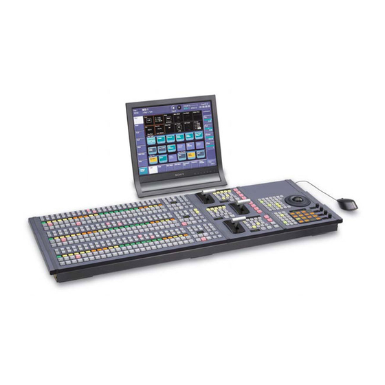
- Page 1 MVS-8000/8000SF System (With CCP-8000 Series Center Control Panel) User’s Guide Multi Format Switcher System [English] Volume 2 1st Edition (Revised 4) Software Version 2.00 and Later...
- Page 2 NOTICE TO USERS © 2001 Sony Corporation. All rights reserved. This manual or the software described herein, in whole or in part, may not be reproduced, translated or reduced to any machine readable form without prior written approval from Sony Corporation.
-
Page 3: Table Of Contents
Table of Contents Chapter 11 DME Operations Three-Dimensional Transformation Operations........13 Basic Operations..................13 Three-Dimensional Parameter Display ..........17 Entering Three-Dimensional Parameter Values........18 Graphics Display ...................19 Canceling Virtual Images ..............22 DME Special Effect Operations ..............23 Border Settings ..................23 Crop Settings ..................26 Beveled Edge Settings................28 Defocus Settings..................31 Blur Settings ..................32 Multi Move Settings ................33... - Page 4 Brick Settings ..................85 Shadow Settings ..................89 Chapter 12 External Devices Control of External Devices.................92 Control of P-BUS Devices ................93 Creating and Editing the P-BUS Timeline ..........93 P-BUS Trigger..................96 Control of GPI Devices ................97 GPI Timeline Creation and Editing............97 Control of VTRs and Disk Recorders............100 Controlling the Tape/Disk Transport ..........100 Checking VTR/Disk Recorder Information ........101 Cueup &...
- Page 5 Path Setting ....................142 Basic Procedure for Path Settings ............142 Executing Effects ..................146 Execution With the RUN Button (Auto Mode)........146 Run Mode Setting................147 Saving Effects....................149 Creating and Saving a Master Timeline...........151 Creating and Saving a Master Timeline Using the Buttons in the Numeric Keypad Control Block .............151 Creating and Saving a Master Timeline With the Menu.....153 Register Operations in the Menus.............156...
- Page 6 Shotbox Execution in the Utility/Shotbox Control Block....195 Shotbox Register Editing ................197 Chapter 16 Engineering Setup Setup for the Whole System...............201 Network Settings (Network Config Menu) .........201 System Settings (System Config Menu) ..........202 Setting the Signal Format and Screen Aspect Ratio (Format Menu) ..204 Selecting the State After Powering On (Start Up Menu) ....205 Reset and Initialization (Initialize Menu)..........207 Installation (Install Menu) ..............208...
- Page 7 Router Interface Settings (Router Menu) ..........284 Tally Group Settings (Group Tally Menu)..........286 Wiring Settings (Wiring Menu) ............287 Tally Generation Settings (Tally Enable Menu) .........289 Tally Copy Settings (Tally Copy Menu) ..........291 Parallel Tally Settings (Parallel Tally Menu)........292 Serial Tally Settings (Serial Tally Menu)..........294 Simple Connection of the MKS-8080/8082 AUX Bus Remote Panel..296 Procedure for Simple Connection ............296 Setting Status of the MKS-8080/8082 in Simple Connection.....296...
- Page 8 Chapter 18 Macros Macro Operations in the Numeric Keypad Control Block.....316 Recalling a Macro Register and Executing a Macro ......317 Creating and Editing a Macro .............318 Saving a Macro..................320 Macro Operations in the Flexi Pad Control Block........322 Recalling a Macro Register and Executing a Macro ......323 Creating and Saving a Macro ..............324 Macro Attachment Assigning ..............328 Setting and Canceling a Macro Attachment........328...
- Page 9 Shotbox Menu ..................358 Macro Menu ..................358 File Menu ....................359 Engineering Setup Menu ..............360 Index ......................363 Table of Contents...
- Page 10 Table of Contents...
- Page 11 Chapter 11 DME Operations Three-Dimensional Transformation Operations ......... 13 Basic Operations................13 Three-Dimensional Parameter Display ........... 17 Entering Three-Dimensional Parameter Values ......18 Graphics Display ................19 Canceling Virtual Images ..............22 DME Special Effect Operations ............23 Border Settings ................23 Crop Settings ...................
- Page 12 Interpolation Settings............... 80 Global Effect Operations ............... 82 Combiner Settings ................82 Brick Settings .................. 85 Shadow Settings ................89...
-
Page 13: Three-Dimensional Transformation Operations
Three-Dimensional Transformation Operations Use the device control block to carry out three-dimensional DME transformations. For details of three-dimensional DME coordinate space, see “Three- Dimensional Transformations” in Chapter 1 (Volume 1). Basic Operations This section explains how to use a trackball-type device control block to carry out three-dimensional transformations. - Page 14 Transforming an image in three-dimensional coordinate space Use the following procedure. With the region selection buttons, select the target channel of the operation. You can press several of the buttons simultaneously to select several channels. In this case, the button that you pressed first lights in green, while buttons pressed subsequently light in amber.
- Page 15 You can magnify and shrink the image with the Z-ring. Rotate counterclockwise to shrink, and clockwise to magnify. To change the aspect ratio of the image: With the [SRC] button selected in step 2, press the [ASP PERS] button, turning it on. You can change the aspect ratio independently on the x- and y-axes with the trackball, and change it simultaneously on both the x- and y- axes with the Z-ring.
- Page 16 • To change on the z-axis, rotate the Z-ring. Parameter values increase as you rotate clockwise, and decrease as you rotate counterclockwise. However, when you have pressed the [LOC XYZ] button to move the image, z-axis parameters increase as you rotate counterclockwise, and decrease as you rotate clockwise.
-
Page 17: Three-Dimensional Parameter Display
Three-Dimensional Parameter Display You can check the values of the three-dimensional parameters in the DME menu. Displaying the three-dimensional parameters in the DME menu In the menu control block, select the top menu selection button [DME]. The DME menu appears. The status area shows the three-dimensional parameters currently controlled by the device control block. -
Page 18: Entering Three-Dimensional Parameter Values
Viewing the three-dimensional parameter details In the DME menu, press the menu title button (the [DME] in the upper left part of the screen). The Status menu appears. This menu shows the three-dimensional parameters for the DME reference channel currently selected in the device control block. Example three-dimensional parameter details Entering Three-Dimensional Parameter Values In addition to setting three-dimensional parameter values with the trackball and... -
Page 19: Graphics Display
Enter a parameter value with the numeric keypad. The number of significant digits after a decimal point is 4. Press the [ENTER] button. The parameter value is changed, and the image changes. To enter difference values You can enter difference values by pressing the [+/−] button, entering the difference from the current value, and pressing the [TRIM] button to confirm. - Page 20 Use the DME menu to make graphics display settings. You can make separate settings for separate channels. To select a target DME channel, use the device control block. Displaying graphics Use the following procedure. In the menu control block, select the top menu selection button [DME]. The DME menu appears.
- Page 21 To automatically erase the graphic display while the keyframes are executing, press the [Auto Erase] button, turning it on, and then set the following parameter. Knob Parameter Adjustment Setting values Recover Time Time until graphic display 0 to 300 (frames) appears again after keyframe execution Three-Dimensional Transformation Operations...
-
Page 22: Canceling Virtual Images
Canceling Virtual Images When a transformation is executed with an extreme degree of perspective, the part of the image which is beyond the imaginary view point can wrap around and show on the other side. The wrapped-around portion is referred to as a virtual image. -
Page 23: Dme Special Effect Operations
DME Special Effect Operations You can use DME to add a variety of special effects. The following types of DME special effects are available. For details of DME special effects, see “DME Special Effects” in Chapter 1 (Volume 1). • Edge effects: Border, Crop, Beveled Edge •... - Page 24 Adding a border Use the following procedure. In the DME menu, select VF1 ‘Edge’ and HF1 ‘Border/Crop.’ The Border/Crop menu appears. Press [Border], turning it on. The Border effect is enabled. You can adjust the border width parameters with the knobs. Note Once the Border effect is enabled, you cannot use the Edge Soft effect (see page 28).
- Page 25 Knob Parameter Adjustment Setting values Density Border density 0.00 to 100.00 −4.50 to +4.50 Border width on top side − Left Border width on left side 8.00 to +8.00 − Right Border width on right side 8.00 to +8.00 −4.50 to +4.50 Bottom Border width on bottom side Density...
-
Page 26: Crop Settings
To set the border color and density, press [Border Color], turning it on, and set the following parameters. Knob Parameter Adjustment Setting values Luminance Luminance 0.00 to 100.00 Saturation Saturation 0.00 to 100.00 359.99 to 0.00 To soften the border edges, press [Border Soft], turning it on, and set the following parameters. - Page 27 • SD format, 4:3 mode Knob Parameter Adjustment Setting values Crop positions on left and right Left value shown sides Crop positions on top and Top value shown bottom sides Crop positions on all sides Left value shown − Crop position on top side 3.00 to +3.00 −...
-
Page 28: Beveled Edge Settings
• HD format, 16:9 mode Knob Parameter Adjustment Setting values Crop positions on left and right Left value shown sides Crop positions on top and Top value shown bottom sides Crop positions on all sides Left value shown − Crop position on top side 9.00 to +9.00 −... - Page 29 Note When the border is enabled, the edge soft function (see page 28) is not available. Set the parameters. The valid ranges of the parameter values depend on the combination of signal format (SD/HD) and aspect ratio (4:3/16:9) selected in the system, as follows.
- Page 30 Knob Parameter Adjustment Setting values Simultaneously adjust width of all Value of H shown four edges In the <Edge Mode> group, select the type of edge. Light: effect of light striking the edge Knob Parameter Adjustment Setting values Adjust luminance of top edge –100.00 to +100.00 Left Adjust luminance of left edge...
-
Page 31: Defocus Settings
To soften the inside of the edges and the boundaries between adjacent edges, turn on [Edge Soft], and adjust the following parameters. Knob Parameter Adjustment Setting values Inner Soft Softness of the inside of edges 0.00 to 100.00 Bound Soft Softness of the edge boundaries 0.00 to 100.00 Bound Soft... -
Page 32: Blur Settings
Set the parameters. • When Video/Key is selected Knob Parameter Adjustment Setting values Horizontal defocusing of video 0.00 to 100.00 and key signals Vertical defocusing of video and 0.00 to 100.00 key signals Horizontal and vertical H value shown defocusing of video and key signals •... -
Page 33: Multi Move Settings
Set the parameters. Knob Parameter Adjustment Setting values Horizontal defocusing of video 0.00 to 100.00 and key signals Vertical defocusing of video and 0.00 to 100.00 key signals Horizontal and vertical H value shown defocusing of video and key signals Multi Move Settings This effect shrinks the image and lines up a number of copies vertically and horizontally. -
Page 34: Sepia Settings
Knob Parameter Adjustment Setting values Size Shrinking ratio 0.00 to 100.00 − Aspect Aspect ratio of shrunken images 100.00 to +100.00 • SD format, 16:9 mode Knob Parameter Adjustment Setting values − Center X x-value of shrinking center point 4.00 to +4.00 −... -
Page 35: Mono Settings
The Color Modify menu appears. Press [Sepia], turning it on. The Sepia effect is enabled. You can adjust the degree of mixing between the sepia image and the original image with the knobs. Set the parameters. Knob Parameter Adjustment Setting values Mix Y Y signal mix amount 0.00 to 100.00... -
Page 36: Posterization And Solarization Settings
Posterization and Solarization Settings The Posterization and Solarization effects both give a painting-like effect by coarsening the gradations of the image. The Posterization effect coarsens luminance gradations, and the Solarization effect coarsens chroma gradations. Applying the Posterization or Solarization effect Use the following procedure. -
Page 37: Contrast Settings
Press [Nega Y] or [Nega C], turning it on, or press both buttons, turning them on. Nega Y: Reverse the luminance. Nega C: Reverse the chroma. Contrast Settings This effect changes the contrast of the luminance and chroma of the image. Applying the Contrast effect Use the following procedure. -
Page 38: Mosaic Settings
Mosaic Settings This effect divides the image into small tiles so that it looks like a mosaic. For an illustrative figure and other information, see “DME Special Effects” in Chapter 1 (Volume 1). Applying the Mosaic effect Use the following procedure. In the DME menu, select VF2 ‘Video Modify’... - Page 39 In the <Freeze Timing> group, select the signal freeze timing. Frame: Freeze one frame of signal. Field 1: Freeze the first field of signal. Note During the execution of a freeze, you cannot change the freeze timing. In the <Freeze> group, press [Hard Freeze], turning it on. The Hard Freeze is executed, displaying a still image.
-
Page 40: Nonlinear Effect Settings
Set the parameters. Knob Parameter Adjustment Setting values Film Ratio of frame advance 0.00 to 100.00 Nonlinear Effect Settings You can add a variety of effects, including effects that change the shape of the image as a whole. Use the following procedure. In the DME menu, select VF4 ‘Non Linear’... - Page 41 Name Effect Multi Mirror Divides the image into originals and reflections, lining page 58 them up vertically and horizontally. Kaleidoscope Creates an image like a view into a kaleidoscope. page 59 Lens Creates an image like a view through a lens. page 60 Circle Makes a circle with the image.
- Page 42 Size not modulated. 1 and 2 are same size. H&V Before modulation Create waves by reducing 1 and expanding 2 the image. SIZE Set the following parameters, according to the selected mode. • When H&V is selected Knob Parameter Adjustment Setting values Amp H Amplitude of waves in horizontal...
- Page 43 Knob Parameter Adjustment Setting values −8.000 to +8.000 Slant Slant of waves a) Set when Lock is on. b) Set when Lock is off. c) Setting for SD 4:3, SD 16:9 d) Setting for HD 4:3, HD 16:9 • When Size is selected Knob Parameter Adjustment...
- Page 44 • When H&V mode is selected Knob Parameter Adjustment Setting values Form H Waveform in horizontal direction 1 to 6 Form V Waveform in vertical direction 1 to 6 • When Size mode is selected Knob Parameter Adjustment Setting values Form H Waveform 1 to 6...
- Page 45 Set the following parameters. • When H&V mode is selected Knob Parameter Adjustment Setting values Size H Amount of horizontal wave 0.00 to 100.00 modulation Offset H Center point of horizontal −8.000 to +8.000 modulation range −32.000 to +32.000 Size V Amount of vertical wave 0.00 to 100.00 modulation...
- Page 46 Set the following parameters. • When H&V mode is selected Knob Parameter Adjustment Setting values Envelope H Smoothness of envelope in 0.00 to 100.00 horizontal direction Envelope V Smoothness of envelope in vertical 0.00 to 100.00 direction • When Size mode is selected Knob Parameter Adjustment...
- Page 47 Twist settings The Twist effect twists the image. To apply the Twist effect With the Twist menu displayed, set the following parameters. Knob Parameter Adjustment Setting values Amp V Amplitude of twist in vertical direction 0.00 to 100.00 Freq V Frequency of twist in vertical direction 0.00 to 100.00 Amount of movement in twist phase −16.00 to +16.00...
- Page 48 To apply the Ripple effect With the Ripple menu displayed, use the following procedure. In the <Mode> group, select the ripple modulation mode. Radial: Points on radii of the same length from the center of the ripples behave in the same way. Angular: Points at the same angle from the center of the ripples behave in the same way.
- Page 49 • When Angular mode is selected Knob Parameter Adjustment Setting values Amp A Ripple amplitude along periphery 0.00 to 100.00 Freq A Ripple frequency along periphery 0.00 to 100.00 −8.000 to +8.000 Direction along periphery in which Offset A to offset ripple phase and amount of movement −100.00 to +100.00 Ripple direction along periphery...
- Page 50 Knob Parameter Adjustment Setting values Shape Ripple shape 1 to 4 −100.00 to +100.00 Aspect Ripple aspect ratio −8.000 to +8.000 Angle Ripple angle a) Set when Lock is on. b) Set when Lock is off. c) Setting for SD 4:3, SD 16:9 d) Setting for HD 4:3, HD 16:9 e) 1 (Circle): Circle 2 (Rectangle): Rectangle...
- Page 51 To limit the ripple range Press [Range], turning it on. Set the following parameters. • When Radial or Shape mode is selected Knob Parameter Adjustment Setting values Size R Amount of ripple modulation 0.00 to 100.00 along radius Offset R Center of modulation range −8.000 to +8.000 along radius...
- Page 52 Other settings You can turn [Lock], [Form], [Random], and [Range Envelope] on to do the following. • Stop the waves • Select the wave shape • Randomize the waveform • Smooth the range envelope when the wave range is limited For Lock, Form, Random, and Range Envelope functions, see “Wave settings”...
- Page 53 Knob Parameter Adjustment Setting values −4.000 to +4.000 Vertical center position −16.000 to +16.000 a) Setting for SD 4:3, SD 16:9 b) Setting for HD 4:3, HD 16:9 To partition into pixels, press [Pixel], turning it on, and set the following parameters.
- Page 54 To set the partition method, press [Partition] and set the following parameters. Knob Parameter Adjustment Setting values Width Width of partition 0.000 to 100.000 Random Degree of randomness in partition 0.000 to 100.000 width −8.000 to +8.000 Angle Partition angle Blind settings The Blind effect divides the image into bars or wedges, with blocks rotating like the slats of venetian blinds.
- Page 55 Knob Parameter Adjustment Setting values −8.000 to +8.000 Phase Partition position To set the wedge center position When Wedge is selected in the <Mode> group, you can set the wedge center position. Press [Position]. Set the following parameters. Knob Parameter Adjustment Setting values −8.000 to +8.000...
- Page 56 Set the following parameters. Knob Parameter Adjustment Setting values Degree of left and right −4.000 to +4.000 separation −16.000 to +16.000 Degree of top and bottom −3.000 to +3.000 separation −12.000 to +12.000 a) Setting for SD 4:3, SD 16:9 b) Setting for HD 4:3, HD 16:9 Split Slide settings The Split Slide effect divides the image into bars which slide alternately in...
-
Page 57: Mirror Settings
Top to Bottom: Reflect top side on bottom. Bottom to Top: Reflect bottom side on top. Top to Left to Right Bottom SONY SO S To set the position of the border between original and reflection Use the following procedure. Press [Position]. - Page 58 Knob Parameter Adjustment Setting values −6.000 to +6.000 Vertical border position −24.000 to +24.000 a) Setting for SD 4:3, SD 16:9 b) Setting for HD 4:3, HD 16:9 Multi Mirror settings The Multi Mirror effect divides the image into originals and reflections, lining them up vertically and horizontally.
- Page 59 Kaleidoscope settings The Kaleidoscope effect creates an image like a view into a kaleidoscope. To apply the Kaleidoscope effect With the Kaleidoscope menu displayed, set the following parameters. Knob Parameter Adjustment Setting values Number Number of blocks 0.00 to 100.00 −8.000 to +8.000 Phase Angle of partition reference point...
- Page 60 Lens settings The Lens effect creates an image like a view through a lens. To apply the Lens effect With the Lens menu displayed, use the following procedure. In the <Mode> group, select the lens shape. • Circle • Rectangle •...
- Page 61 To make only the lens part visible Press [Lens Only], turning it on, to remove the parts of the image outside the lens. To set the lens center position Use the following procedure. Press [Position], turning it on. Set the following parameters. Knob Parameter Adjustment...
- Page 62 Knob Parameter Adjustment Setting values −4.000 to +4.000 Position H Horizontal curve center position −16.000 to 16.000 −3.000 to +3.000 Position V Vertical curve center position −12.000 to +12.000 a) Setting for SD 4:3, SD 16:9 b) Setting for HD 4:3, HD 16:9 Page Turn settings The Page Turn effect turns the image like turning a page.
- Page 63 2nd Ch: Use the 2nd channel video signal. To select “2nd Ch,” it is first necessary to select the second DME on the keyer using DME. Adjust the following parameters, according to the selected input signal. • When Flat is selected Knob Parameter Adjustment...
- Page 64 The procedure for selecting the input signal in the <Back Video> group is the same as for the Page Turn menu, For details about operation, see “Page Turn settings” (page 62). Sphere settings The Sphere effect winds the whole image onto a sphere. To apply the Sphere effect Display the Sphere menu.
- Page 65 Knob Parameter Adjustment Setting values Curve Degree to which image periphery 0.00 to 100.00 expands −100.00 to +100.00 Aspect Aspect ratio of waveform −8.000 to +8.000 Angle Slant of waveform To make the fragments stardust Use the following procedure. Press [Pixel], turning it on. Set the following parameters.
- Page 66 Knob Parameter Adjustment Setting values −8.000 to +8.000 Outer Amount of rotation outside of Area Area Region of swirl 0.00 to 100.00 To make the tip of the swirl stardust Use the following procedure. Press [Pixel], turning it on. Set the following parameters. Knob Parameter Adjustment...
- Page 67 To make transition settings, press [Transition] and set the following parameters. Knob Parameter Adjustment Setting values Transition Degree of transition 0.00 to 100.00 Curve Degree to which image stretches 0.00 to 100.00 Random Degree of jaggies at melted part 0.00 to 100.00 To make wave settings for melting part, press [Border] and set the following parameters.
-
Page 68: Lighting Settings
Set the following parameters. Knob Parameter Adjustment Setting values Density Degree to which image 0.00 to 100.00 disappears Random Degree to which pixel positions 0.00 to 100.00 become more randomized further from the center Character Trail settings The Character Trail effect extends the edge of the image like a trail. To apply the Character Trail effect With the Character Trail menu displayed, set the following parameters. - Page 69 Note You cannot select Bar for an image subjected to a nonlinear effect. Applying the Lighting effect Use the following procedure. In the DME menu, select VF5 ‘Light/Trail’ and HF1 ‘Lighting.’ The Lighting menu appears. Press [Lighting], turning it on. The Lighting effect is enabled.
- Page 70 Shade area Ambient area Highlight area The three regions for which the light intensity can be set Setting the bar shape of the highlight area When you select [Bar] or [Preset] in step 2, use the following procedure to set the shape of the bar.
- Page 71 Setting the color of the light in the highlight area To set the color of the light in the highlight area, use the following procedure. Turn [Light Color] on. Adjust the following parameters. Knob Parameter Adjustment Setting values Luminance Luminance 0.00 to 100.00 Saturation Saturation...
-
Page 72: Trail Settings
Trail Settings This effect recursively freezes the input video at regular intervals so that a trail of afterimages is created. For an illustrative figure and other information, see “DME Special Effects” in Chapter 1 (Volume 1). Notes • The trail effect can be applied to two channels at the same time. •... - Page 73 Selecting the source to create a trail In the <Trail Source> group, select the source to create a trail. Freeze Video: Use freeze images of the input video as source of the trail. Flat Color: Use a flat color matte as source of the trail. You can set the following parameters with the knobs.
-
Page 74: Motion Decay Settings
Set the following parameters. Knob Parameter Adjustment Setting values Trail Dust Amount of the trail disappearing as 0.00 to 100.00 stardust Dust Soft Timing with which stardust 0.00 to 100.00 disappears Dust Size Size of stardust 0.00 to 100.00 Dust Aspect Aspect ratio of stardust –100.00 to +100.00 a) The way in which the trail disappears is affected by both Decay and Trail Dust parameter... -
Page 75: Keyframe Strobe Settings
In the <Decay Mix Mode> group, select the way in which the video signal is blurred. Soft: mix the live image with the afterimage. Hard: show the lighter of the live image and afterimage. To erase the afterimage, press [Decay Eraser], turning it on. To erase the afterimage from memory each time a keyframe is passed Press [Decay Eraser], turning it on. - Page 76 Note When you turn on keyframe strobe, if the trail or motion decay effect is on, it automatically goes off. Leaving a trail of afterimages of the image Use the following procedure. In the DME menu, select VF5 ‘Light/Trail’ and HF4 ‘KF Strobe.’ The KF Strobe menu appears.
-
Page 77: Background Settings
Frame: freeze in frame units. Field: freeze in field units. To erase the afterimage from memory each time a keyframe is passed Press [KF Strobe Eraser], turning it on. When the effect passes a keyframe, the afterimage is erased before writing a new afterimage. -
Page 78: Separate Sides Settings
The Bkgd menu appears. Press [Bkgd], turning it on. The Background effect is enabled. You can adjust the parameters with the knobs. Set the parameters. Knob Parameter Adjustment Setting values Luminance Luminance 0.00 to 100.00 Saturation Saturation 0.00 to 100.00 359.99 to 0.00 Separate Sides Settings This effect applies separate video signals and key signals to the front and back... -
Page 79: Key Density Settings
For an illustration of signal inversion, see “DME Special Effects” in Chapter 1 (Volume 1). Applying the Invert effect Use the following procedure. In the DME menu, select VF6 ‘Input/Output’ and HF2 ‘Video/Key.’ The Video/Key menu appears. In the <Front> group (to invert front signals) or the <Back> (to invert back signals), press the following buttons, turning them on. -
Page 80: Interpolation Settings
Selecting the key source signals Use the following procedure. In the DME menu, select VF6 ‘Input/Output’ and HF2 ‘Video/Key.’ The Video/Key menu appears. In the <Front Key> group or <Back Key> group respectively, press one of the following, turning it on. Ext Key: use the key signal sent from the switcher as the key source. - Page 81 When you select Adaptive Y/C or Adaptive Y in step 2, set the following parameter. Knob Parameter Adjustment Setting values Mode Degree of motion detection 1 to 4 In the <Key Field/Frame Mode> group, select the interpolation method for the key signal. Adaptive: Detect changes in the luminance component of the key signal separately, and switch automatically between fields and frames.
-
Page 82: Global Effect Operations
Global Effect Operations Global effects are special effects created by combining the images of successive channels. The following types of global effects are available. • Combiner • Brick • Shadow For details of these global effects, see “Global Effects” in Chapter 1 (Volume Operations common to all global effects In this section, explanations of the operating procedures for individual global effects begin with selections from VF1 ‘Ch1’... - Page 83 If either of [Mix] and [Auto] is on, turn it off. Set the overlap priority for “Ch1+Ch2+Ch3” or “Ch1+Ch2, Ch3+Ch4” as follows. For case “Ch1+Ch2+Ch3” Under <Priority1> to <Priority3>, press [Ch1], [Ch2], and [Ch3], respectively, to set the overlap priority. Priority1: Select the channel with the highest priority.
- Page 84 Adjust the following parameters. For Ch1+Ch2 Knob Parameter Adjustment Setting values Mix degree 0.00 to 100.00 a) See “Global Effects” in Chapter 1 (Volume 1). For Ch1+Ch2+Ch3 Knob Parameter Adjustment Setting values Mix1 Mix degree for mix of 0.00 to 100.00 channel 1 with result of Mix2 Mix2...
-
Page 85: Brick Settings
Note It is not possible to make images intersect. If an image is rotated, the priority is determined by the position on the z-axis of the center of the image. Brick Settings This effect creates a rectangular parallelepiped from 3 successive channels. For an illustration, see “Global Effects”... - Page 86 Specify the way to insert the side images when the height is changed by pressing one of the following buttons in the <Side V> group or the <Side H> group. Crop: Crop the parts that do not fit into the side without shrinking the picture.
- Page 87 The set position becomes the upper left corner of Side V or Side H. The right and bottom sides of the inserted image are set automatically. Compress: Images are inserted after being compressed. You can set the following parameters. Parameter limits vary as shown below, depending on the signal format (SD or HD) and aspect ratio (4:3 or 16:9) selected in the system.
- Page 88 • HD format, 16:9 mode Knob Parameter Adjustment Setting values − Position of top crop 9.00 to +9.00 − Left Position of left crop 16.00 to +16.00 − Right Position of right crop 16.00 to +16.00 − Bottom Position of bottom crop 9.00 to +9.00 Rotation Angle of rotation, when rotated...
-
Page 89: Shadow Settings
Shadow Settings This effect uses two successive channels to give an image a shadow. For an illustration, see “Global Effects” in Chapter 1 (Volume 1). Applying the Drop Shadow effect Use the following procedure. In the Global Effect>Ch1 - Ch4 menu, select HF3 ‘Shadow.’ The Shadow menu appears. - Page 90 When you select Flat Color in step 4, adjust the parameters. Knob Parameter Adjustment Setting values Luminance Luminance 0.00 to 100.00 Saturation Saturation 0.00 to 100.00 359.99 to 0.00 Global Effect Operations...
-
Page 91: Chapter 12 External Devices
Chapter 12 External Devices Control of External Devices..............92 Control of P-BUS Devices ..............93 Creating and Editing the P-BUS Timeline ........93 P-BUS Trigger ................. 96 Control of GPI Devices................97 GPI Timeline Creation and Editing ..........97 Control of VTRs and Disk Recorders..........100 Controlling the Tape/Disk Transport.......... -
Page 92: Control Of External Devices
For VTRs and disk recorders, you can also carry out operations using the device control block. Notes • To operate P-BUS devices, VTRs, and disk recorders in the MVS-8000 system, the following settings are required on the DCU 9-pin serial port. - Device type setting... -
Page 93: Control Of P-Bus Devices
Control of P-BUS Devices Creating and Editing the P-BUS Timeline This section describes how to set an action for a keyframe point, and edit the P-BUS timeline. For details of keyframe creation and editing operations, see “Creating and Editing Keyframes” (page 126). Note Using the P-BUS timeline function requires the P-BUS control mode to be set to [Timeline]. - Page 94 a) 1: Off (no specification) 2: Store 3: Recall 4: Trigger If in step 3 you selected 2 (Store), 3 (Recall), or 4 (Trigger), turn knob 3 to select the register number or trigger number. The indication for knob 3 changes to reflect the selection of Store, Recall, or Trigger.
- Page 95 Setting the action for a rewind operation On the P-BUS timeline, when the [REWIND] button in the keyframe control block is pressed the action set for the first keyframe is not executed; when the [RUN] button is pressed, then the first keyframe action is executed. To execute an action when the [REWIND] button is pressed, it is necessary to set this action (Rewind Action).
-
Page 96: P-Bus Trigger
P-BUS Trigger “P-BUS trigger” is a function whereby a button operation in the numeric keypad control block or keyframe control block outputs an action command to a P-BUS device. Note To use the P-BUS trigger function, the P-BUS control mode must be set to [Trigger]. -
Page 97: Control Of Gpi Devices
Control of GPI Devices GPI Timeline Creation and Editing This section describes how to set GPI output ports to be registered at a keyframe point, and how to carry out creation and editing of the GPI timeline. For details of keyframe creation and editing operations, see “Creating and Editing Keyframes”... - Page 98 • Turn the knob to make the selection. Knob Parameter Setting Setting values GPI Port No SCU/DCU GPI port to be the 1 to 3 trigger output destination a) 1: Off (no specification) 2: Control panel (SCU) GPI port 3: DCU GPI port If in step 3 you selected 2 (SCU) or 3 (DCU), then use the knob to select the port number.
- Page 99 In the list on the right, select “Off.” Press [Set]. To clear the settings for all devices (GPI output ports) in a single operation Press [All Off]. Setting the action for a rewind operation On the GPI timeline, when the [REWIND] button in the keyframe control block is pressed the action set for the first keyframe is not executed;...
-
Page 100: Control Of Vtrs And Disk Recorders
Control of VTRs and Disk Recorders To control a VTR or disk recorder in the MVS-8000 system, the following settings are required. • Button assignment: For a VTR or disk recorder connected to the DCU 9-pin serial port, assign a device selection button in the device control block. -
Page 101: Checking Vtr/Disk Recorder Information
Selecting a VTR/disk recorder To select the VTR/disk recorder to be controlled, in the device selection buttons of the device control block, press a selection of the [DEV1] to [DEV12] buttons, turning them on. Controlling the tape/disk transport Using the buttons in the device control block, you can control the VTR tape transport or the disk recorder disk transport. -
Page 102: Cueup & Play
Cue>: Cueing up in the forward direction. Cue<: Cueing up in the reverse direction. Eject: Ejecting cassette. Stb Off: Stopped in “standby off” mode. Stop: Stopped in “standby on” mode. Play: Playing. FF: Fast forwarding. Rewind: Rewinding. Shtl>: Playing in the forward direction in shuttle mode. Shtl<: Playing in the reverse direction in shuttle mode. - Page 103 Making and saving settings relating to Cueup & Play Use the following procedure. Press the [EFF] button in the numeric keypad control block, turning it on. This assigns the numeric keypad control block to keyframe operations, and the [RCALL] button lights. Press the region selection button for the region for which you want to make the setting, turning it on.
- Page 104 press the [START TC] button. Alternatively, in the Device>DDR/ VTR>Cueup & Play menu, enter the timecode for the start point. If using the [START TC] button, each time you press the button overwrites the start point timecode. For details of settings in the Cueup & Play menu, see “Setting the start point, stop point, and start delay time in a menu”...
- Page 105 The [RCALL] button in the numeric keypad control block lights. With the region selection buttons in the numeric keypad control block, select the region. You can also select more than one button. Enter the number of the register to be recalled with the numeric keypad buttons.
- Page 106 • To set the stop point, press [SET] in the <Stop TC> group. • To set the start delay time point, press [SET] in the <Delay> group. A timecode window appears. Set the timecode value for the start point, stop point, or start delay time. Note You can enter a start delay time in the range that depends on the signal format as follows:...
-
Page 107: Vtr/Disk Recorder Timeline
VTR/Disk Recorder Timeline Note When executing a VTR/disk recorder timeline using a disk recorder, note the following points. • When carrying out keyframe settings, be sure to recall the file for operation first. • Set the keyframe duration to at least 30 frames. •... - Page 108 • During file playback, to play the next keyframe at variable speed, for the next keyframe set variable speed only, and do not set the start point (see figure below). Playback Playback at set variable speed a) In keyframe 2, set variable speed only, and do not set the start point. •...
- Page 109 Using any of the following methods, select the device for which you want to set the action. • Press directly on the list in the status area. • Press the arrow keys to scroll the reverse video cursor. • Turn the knob to make the selection. Knob Parameter Setting...
- Page 110 Set the start point as a timecode value. Press [Enter]. The new start point setting is reflected in the status area. To set the stop point, in the <Stop TC> group press the [Set] button. A timecode window appears. Set the stop point as a timecode value. If you do not want to set the stop point, skip to step 11.
- Page 111 [STOP TC] button: Set the stop point of the keyframe point to the current time. [CUE] button: Cue up to the start point set for the keyframe point. To display or check the settings, use the Device>DDR/VTR>Timeline menu. To test an action command output To test an action command output, select the desired device from the upper list in the status area, and press [Test Fire].
-
Page 112: Disk Recorder File Operations
Disk Recorder File Operations To carry out disk recorder file operations, use the Device menu. Refreshing (recalling) the disk recorder file list Use the following procedure. In the Device menu, press VF3 ‘VTR’ and HF3 ‘File List.’ The Device>VTR/DDR> File List menu appears. In the status area, two lists appear. - Page 113 In the Device menu, press VF3 ‘VTR’ and HF3 ‘File List.’ The Device>VTR/DDR>File List menu appears. Select the device for which you want to recall the file list, using the knob. Knob Parameter Setting Setting values Device number 1 to 12 In the <Sort>...
- Page 114 Control of VTRs and Disk Recorders...
-
Page 115: Chapter 13 Keyframe Effects
Chapter 13 Keyframe Effects Sequence of Keyframe Operations............117 Displaying the Timeline Menu............. 118 Interpreting the Timeline Menu............. 118 Recalling a Register ................121 Specifying the Region and Edit Points..........124 Creating and Editing Keyframes ............126 Creation ..................126 Insertion .................. - Page 116 Creating and Saving a Master Timeline Using the Buttons in the Numeric Keypad Control Block....... 151 Creating and Saving a Master Timeline With the Menu ....153 Register Operations in the Menus............156 Effect Attribute Settings ..............156 Effect Status Display ..............157 Effect Register Editing ..............
-
Page 117: Sequence Of Keyframe Operations
Sequence of Keyframe Operations The following table shows the principal operations involved in the sequence from creating keyframes to executing an effect. For details of each operation, see the page number in parenthesis. For an overview, see “Keyframes” in Chapter 1 (Volume 1). Recalling a register (see page 121) To create a new effect, recall an empty register;... -
Page 118: Displaying The Timeline Menu
Displaying the Timeline Menu By displaying the Timeline menu, you can view keyframe effects on the timeline for each region, and the associated information. Recalling the Timeline menu To recall the Timeline menu, use the following procedure. In the menu control block, press the top menu selection button [KEYFRAME]. - Page 119 a Keyframe status This shows the region name, register number, register name, number of remaining keyframes, current position and timecode with regard to the reference region. b Region name and register number This shows the region name and the number of the register recalled in this region.
- Page 120 Selecting the region displayed In the Timeline menu, there is a timeline display for each region, but you can also restrict the display to certain regions. Use the following procedure. In the Key Frame menu, press HF5 ‘Misc.’ The Key Frame>Misc menu appears. In the <Timeline Display>...
-
Page 121: Recalling A Register
Recalling a Register Use the numeric keypad control block to recall a register. For each region there are 99 registers dedicated to keyframes, numbered from 1 to 99. When creating an effect as a user programmable DME, use a 3-digit register number which is commonly used for all DME regions (channels). - Page 122 Press the button corresponding to the region you want to select, turning it You can also press more than one button. [M/E 1], [M/E 2], [M/E 3], [P/P]: These select the corresponding M/E-1, M/E-2, M/E-3, and PGM/PST regions. [USER 1] to [USER 8]: These select the USER regions. [DME 1] to [DME 8]: These select DME channels.
- Page 123 To apply a temporary attribute (effect dissolve), press the [+/–/EFF DISS] button. Note It is not possible to apply temporary attributes to the master timeline. Press the [ENTER] button. This recalls the specified register. When the master timeline is recalled, the region selection buttons light according to the saved region information.
-
Page 124: Specifying The Region And Edit Points
Specifying the Region and Edit Points Selecting the region in which editing applies Select the region in which the editing is applied by the effect consisting of keyframes, using the region selection buttons in the numeric keypad control block. (See step 2 (page 122) in “Recalling a register.” Setting the edit points EDIT ENBL button CONST DUR button... - Page 125 • To move the edit point to a specified timecode, press the [GO TO TC] button, then enter the timecode value with the numeric keypad in the numeric keypad control block, and press the [ENTER] button to confirm. To enter a difference value When moving to a point specified with the [GO TO KF] button or [GO TO TC] button, you can also enter the difference from the current keyframe number or timecode value.
-
Page 126: Creating And Editing Keyframes
Creating and Editing Keyframes For details of keyframe editing, see “Effect Editing” in Chapter 1 (Volume 1). Creation Creating new keyframes To create new keyframes, after recalling an empty register, use the following procedure to create and insert each new keyframe. Use the keyframe control block for carrying out the operation. -
Page 127: Insertion
Insertion Inserting keyframes To insert a keyframe in an existing effect, use the following procedure in the keyframe control block. Press the [EDIT ENBL] button, turning it on. Stop the effect at the desired edit point. Create the image for the keyframe you want to insert. Press the [INS] button. - Page 128 Using image transformations or adding special effects, modify the keyframe. Press the [MOD] button. This modifies the keyframe. Modifying more than one keyframe simultaneously You can modify a number of keyframes simultaneously. There are three different cases for this operation. •...
- Page 129 To modify all keyframes in the effect Use the following procedure. Press the [EDIT ENBL] button, turning it on. Carry out the necessary modifications on any keyframe. Press the [ALL] button, turning it on. Press the [MOD] button. Alternatively, hold down the [SHIFT] button and press the [MOD] button.
- Page 130 This makes the modification simultaneously to all keyframes in the specified keyframe range. Differences in the changes when a number of keyframes are modified When you select a number of keyframes to modify, and press the [MOD] button alone or in combination with the [SHIFT] button, the result of the operation differs as shown below.
-
Page 131: Deletion
Modifying the keyframes by holding down the [SHIFT] button and pressing the [MOD] button The modified parameter values are taken as relative values, which modify all of the selected keyframes. : Background A : Background B Effect execution Keyframe 1 Keyframe 2 Keyframe 3 Modify keyframe 2. -
Page 132: Movement
Press the [EDIT ENBL] button, turning it on. Stop the effect at the desired edit point. When the edit point is on a keyframe, this is what you delete. If the edit point is between two keyframes, the previous keyframe is what you delete. To delete a number of keyframes in a single operation, press the [FROM TO] button or the [ALL] button, turning it on. -
Page 133: Copying
Move the edit point to the position to which you want to move the keyframe. Press the [PASTE] button. This inserts the keyframe you have moved after the current keyframe. In constant duration mode, the moved keyframe overwrites the edit point. To insert the moved keyframe before a keyframe Hold down the [SHIFT] button, and press the [PASTE] button to insert the moved keyframe before the current keyframe. -
Page 134: Pause
Pause To apply a pause to a keyframe, use the following procedure. Press the [EDIT ENBL] button, turning it on. Stop the effect on the keyframe to which you want to apply a pause. Press the [PAUSE] button. This applies a pause to the specified keyframe. Keyframe Loop (Repeated Execution of a Specified Range) By setting the range of the loop within the effect, and the number of loop... - Page 135 With the numeric keypad buttons of the numeric keypad control block, enter the number of the last keyframe in the loop range (end point). (Here, by way of example, keyframe 5 is the end point.) 2 TO Press the [ENTER] button to confirm the entry. The display changes as follows, prompting you to enter the loop count.
- Page 136 To change the loop count only, press the [ENTER] button, then skip to step When you press the [CLEAR] button, this appears as follows. Enter the keyframe number for the new start point, and press the [ENTER] button. Enter the keyframe number for the new end point, and press the [ENTER] button.
-
Page 137: Undoing An Edit Operation
Before deletion Deletion After deletion : Loop range Example 2: If keyframe 3 is added, the end point keyframe number moves back. Before addition Addition After addition : Loop range Example 3: If the keyframe at the end of the loop range (the end point) is deleted, the keyframe loop settings are all cleared, as follows, and the [KF LOOP] button goes off. -
Page 138: Duration Mode Setting
Duration Mode Setting There are two keyframe duration modes: variable duration mode, and constant duration mode in which the effect duration is fixed. (See “Duration modes” in Chapter 1 (Volume 1).) • To select variable duration mode, turn the [CONST DUR] button off. •... -
Page 139: Time Settings
Time Settings You can determine the execution time of an effect by setting either the keyframe durations or the effect duration. For details of keyframe duration and effect duration, see “Time Settings” in Chapter 1 (Volume 1). Setting the Keyframe Duration KF DUR button EDIT ENBL button EFF DUR button... -
Page 140: Setting The Effect Duration
Setting the keyframe duration You can set the value of the keyframe duration independently for each keyframe, by the following method. Press the [EDIT ENBL] button, turning it on. Stop the effect on the keyframe for which you want to set the duration. The time from this keyframe to the following keyframe is what you set. -
Page 141: Setting The Delay
Using the numeric keypad in the numeric keypad control block, enter the timecode value for the effect duration, as a maximum of six digits. For example, to set 3 minutes 7 seconds and 15 frames, enter 30715. You can also use the [TRIM] button to enter a difference value. (See “To enter a difference value”... -
Page 142: Path Setting
Path Setting The term “path” refers to the specification of how interpolation is carried out from one keyframe to the next. For details of the notion of path, see “Paths” in Chapter 1 (Volume 1). Set keyframe paths in the Key Frame>Path menu. To access the Key Frame>Path menu In the top menu selection buttons of the menu control block, press [KEYFRAME], then select HF3 ‘Path.’... - Page 143 Changing the path type for Curve Use the following procedure. In the Path menu, press [M/E-1]. The M/E-1 menu appears. Press the Curve path type indication for the Key1 item that you want to change. A path selection window appears. Press the indication for the desired path type, to select it.
- Page 144 The status area reflects the selected path type. At this point, depending on the setting for Curve, the effect for Hue and Xpt is also affected as shown in the following table. In the menu, the Hue and Xpt settings do not change, but the path type indication is dimmed out. Curve setting Hue change Xpt change...
- Page 145 Press the indication for the desired path type, to select it. Xpt Hold off: When replaying a keyframe, change the inputs to the settings saved in memory. Xpt Hold on: When replaying a keyframe, do not change the inputs. Path Setting...
-
Page 146: Executing Effects
Executing Effects By means of the [RUN] button in the keyframe control block, you can play an effect as a continuously varying image. This is referred to as effect execution. See also “Effect Execution” in Chapter 1 (Volume 1). It is also possible to execute an effect from the device control block (see Chapter 2 (Volume 1)). -
Page 147: Run Mode Setting
Executing an effect automatically Use the following procedure. Select the region in which you want to execute the effect, using the region selection buttons in the numeric keypad control block. (See step 2 (page 122) of “Recalling a register.”) With the numeric keypad, enter the number of the register in which the effect you want to execute is saved, and press the [ENTER] button to confirm. - Page 148 Executing an effect up to the next keyframe Use the following procedure. Press the [STOP NEXT KF] button, turning it on. Press the [RUN] button. This executes the effect as far as the next keyframe. When the [REV] button is lit, it is executed as far as the previous keyframe. Repeating an effect Use the following procedure.
-
Page 149: Saving Effects
Saving Effects When you recall an effect, the currently recalled effect is automatically saved in a register. This is referred to as the auto save function. You can disable the auto save function in a Setup menu. By means of the following operation, you can also specify a register and save an effect in it. - Page 150 Press the [ENTER] button. This saves the current effect in the specified register, and turns off the [STORE] button. The [RCALL] button and [STORE STATS] button both light. To undo the saving of an effect Immediately after saving an effect, hold down the [STORE STATS] button and press the [UNDO] button to undo the save.
-
Page 151: Creating And Saving A Master Timeline
Creating and Saving a Master Timeline Creating and Saving a Master Timeline Using the Buttons in the Numeric Keypad Control Block Creating and saving a master timeline You can save region information (information on any regions, including the register numbers associated with the regions) referred to as a master timeline in a dedicated register. - Page 152 Press the [ENTER] button. The regions selected in step 3 and the register numbers recalled in those regions are saved in the master timeline register, and the [STORE] button goes off. At the same time, the [RCALL] button lights. Notes •...
-
Page 153: Creating And Saving A Master Timeline With The Menu
Press the buttons for the regions you want to save on the master timeline (here, [M/E-1] and [M/E-2]), turning them on. Press the region selection button [MASTR], turning it on. The display shows the register number last used for master timeline operation. - Page 154 The status area shows the master timeline register names, register lock status, register number for each region, and so on. If required, press the following buttons in the status area to change the region display. M/E, P/P: indicate assignment of M/E-1 (“M/E1”), M/E-2 (“M/E2”), M/ E-3 (“M/E3”), and P/P (“P/P”).
- Page 155 Turn the knob to select the number of the effect register. Knob Parameter Adjustment Setting values Reg No Effect register number 1 to 99 Repeat steps 3 and 4 as required to set all regions and register numbers to be saved on the master timeline. In the <Store>...
-
Page 156: Register Operations In The Menus
Register Operations in the Menus Using the Effect menu, you can carry out the following effect register operations. • Attribute setting • Status display • Register editing To display the Effect menu Press the top menu selection button [EFF] in the menu control block. Effect Attribute Settings Applying effect dissolve To apply the “effect dissolve”... -
Page 157: Effect Status Display
Press [Effect Dissolve], turning it on. Turn the knob to set the duration. Knob Parameter Adjustment Setting values Duration Dissolve duration 0 to 999 (frames) Effect Status Display The Effect>Effect menu displays the following information. Region name: The selected region name appears in the upper part of the list. Register number Register name Write-protected status: When the register is write-protected, a letter “L”... - Page 158 Press the region display in the upper part of the list to display a selection window, then select the region in the selection window. Selecting multiple regions is also possible. Press [OK]. The selected region name appears in the upper part of the list. Using either of the following methods, select the register.
- Page 159 Using any of the following methods, select the desired registers. • Press directly on the list in the status area. • Press the arrow keys to scroll the reverse video cursor. • Use the knobs. Knob Parameter Adjustment Setting values From Reg Copy source register number 1 to 99...
- Page 160 • Turn the knobs to make the settings. Knob Parameter Adjustment Setting values From Reg The register coming afterwards when 1 to 99 merged To Reg The register coming before when merged 1 to 99 Press [Merge]. This carries out the merge. Deleting data from effect registers Use the following procedure.
- Page 161 Press the region display in the upper part of the list to display a selection window, then select the region in the selection window. Selecting multiple regions is also possible. Press [OK]. The selected region name appears in the upper part of the list. Using any of the following methods, select the register you want to name.
- Page 162 Register Operations in the Menus...
-
Page 163: Chapter 14 Snapshots
Chapter 14 Snapshots Snapshot Operations From the Numeric Keypad Control Block ..164 Saving and Recalling Snapshots............ 165 Snapshot Operations in the Flexi Pad Control Block ....... 170 Banks and Registers............... 171 Saving and Recalling Snapshots............ 172 Snapshot Operations in the Menus ............. 176 Setting Snapshot Attributes ............ -
Page 164: Snapshot Operations From The Numeric Keypad Control Block
Snapshot Operations From the Numeric Keypad Control Block The term “snapshot” refers to a function whereby the various settings required to apply a particular effect to an image are saved in memory as a set of data, for recall as required to recover the same effect-applied state. For an overview of snapshots, see “Snapshots”... -
Page 165: Saving And Recalling Snapshots
Saving and Recalling Snapshots Snapshot operations with the numeric keypad control block use the following buttons. UNDO button +/−/EFF DISS button STORE STATS button SNAPSHOT button Display CLR/AUTO SNAP SHOT TRANS MCRO UNDO TRANS button SHOT RATE STORE MASTR P-BUS STATS DISS AUTO... - Page 166 [USER 1] to [USER 8]: These select the USER regions. [DME 1] to [DME 8]: These select DME channels. [ALL]: This selects all regions. Note The regions that can be selected simultaneously are those assigned to the region selection buttons in the numeric keypad control block. (See “Assigning the region selection buttons in the numeric keypad control block”...
- Page 167 Note In the numeric keypad control block, it is not possible to apply the cross- point hold and GPI output attributes. For these, see “Applying snapshot attributes” (page 176). Press the [ENTER] button. This saves the snapshot, and the [STORE] button goes off. The [RCALL] and [STORE STATS] buttons light.
- Page 168 The display shows the name of the reference region and the number of the register previously recalled for that region. Enter the desired register number from the numeric keypad. See step 5 (page 166) in “Saving a snapshot from the numeric keypad control block.”...
- Page 169 Note It is not possible to cancel recalling a master snapshot. Creating and saving a master snapshot with the numeric keypad control block To create and save a master snapshot with the numeric keypad control block, refer to the operations in “Creating and Saving a Master Timeline Using the Buttons in the Numeric Keypad Control Block”...
-
Page 170: Snapshot Operations In The Flexi Pad Control Block
Snapshot Operations in the Flexi Pad Control Block In the Flexi Pad control block on each of the M/E-1 to M/E-3 and PGM/PST banks, you can only carry out operations on snapshots for that bank. It is therefore not necessary to select a region. UNDO button SNAPSHOT button Numeric display STORE STATS button... -
Page 171: Banks And Registers
Banks and Registers In a standard type Flexi Pad control block, in order to handle the 99 registers, they are considered in groups. These groups are called “banks,” and there are ten banks, numbered from 0 to 9. The correspondence between banks and registers is shown in the following table. -
Page 172: Saving And Recalling Snapshots
Saving and Recalling Snapshots Saving a snapshot with the Flexi Pad control block As an example, to save a snapshot on the M/E-1 bank, use the following procedure. In the M/E-1 bank, make the settings for the state you want to save as a snapshot. - Page 173 Not lit: Register not containing anything To apply an attribute, hold down the [SNAPSHOT] button, and in the memory recall section, press a button as follows, turning it on. Attribute to apply Button Effect dissolve [EFF DISS] button Auto transition [AUTO TRANS] button For details of attributes and available attributes, see “Snapshot Attributes”...
- Page 174 In the M/E-1 bank Flexi Pad control block, press the [SNAPSHOT] button. This allocates the Flexi Pad control block to snapshot operations. The numeric display shows the last selected bank number and the register number last recalled on the bank. Select the bank for recall.
- Page 175 Deleting a snapshot from a Flexi Pad control block As an example, to delete a snapshot on the M/E-1 bank, use the following procedure. In the M/E-1 bank Flexi Pad control block, press the [SNAPSHOT] button. This allocates the Flexi Pad control block to snapshot operations. The numeric display shows the last selected bank number and the last recalled register number on the corresponding switcher bank.
-
Page 176: Snapshot Operations In The Menus
Snapshot Operations in the Menus You can also set snapshot or key snapshot attributes in the Snapshot menu, which also displays the status of the registers. To access the Snapshot menu, press the top menu selection button [SNAPSHOT] in the menu control block. In the Snapshot menu, as well as setting snapshot attributes, you can carry out editing operations on snapshots, including copy and delete. - Page 177 In the <Attribute> group, press the buttons for the attributes you want to apply, turning them on. Carry out the following procedures for each of the attributes. To apply the cross-point hold attributes Press [XPT Hold], turning it on. The Snapshot>Attribute>Xpt Hold menu appears. The status area shows a list of the currently selected regions and bus names.
-
Page 178: Snapshot Status Display
Turn the knob to set the port number. Knob Parameter Adjustment Setting values GPI Out GPI output port number 1 to 8 Port For details of attributes and available attributes, see “Snapshots” in Chapter 1 (Volume 1). Snapshot Status Display The Snapshot>Attribute menu displays the following information. -
Page 179: Setting Key Snapshot Attributes
When an effect dissolve is set: Displayed Attributes set character codes Duration value The effect dissolve attribute is set, with the displayed duration. When an auto transition is set: Displayed Attributes set character codes Auto transition is set. When a GPI output is set: Displayed Attributes set character codes... -
Page 180: Creating And Saving A Master Snapshot
• Turn the knobs to make the setting. Knob Parameter Adjustment Setting values Register Register number 1 to 4 Select number of registers 1 to 4 • To select all registers, press [All]. In the <Recall Mode> group, select one of the following modes for save and recall operations. -
Page 181: Snapshot Register Editing
User: User1 (“USR1”) to User8 (“USR8”) DME: indicate assignment of DME ch1 (“DME1”), ch2 (“DME2”), ch3 (“DME3”), ch4 (“DME4”), ch5 (“DME5”), ch6 (“DME6”), ch7 (“DME7”), and ch8 (“DME8”). Snapshot Register Editing You can carry out the following editing on snapshot registers. (You can use similar procedures also on master snapshot, wipe snapshot, DME wipe snapshot and key snapshot registers.) •... - Page 182 Snapshot Operations in the Menus...
-
Page 183: Chapter 15 Utility/Shotbox
Chapter 15 Utility/Shotbox Utility Execution ................... 184 Executing a Utility With the User Preference Buttons (Menu Control Block) ............184 Executing a Utility in the Utility/Shotbox Control Block ..... 185 Shotbox Register Creation ..............187 Creating a Shotbox Register in the Numeric Keypad Control Block .............. -
Page 184: Utility Execution
Utility Execution You can assign actions such as menu shortcuts, function enabling and disabling, and recalling shotbox registers to buttons in the menu control block and utility/shotbox control block. Use the setup menu to make the assignment. For details of the menu control block and utility/shotbox control block, see “Menu Control Block”... -
Page 185: Executing A Utility In The Utility/Shotbox Control Block
Executing a Utility in the Utility/Shotbox Control Block Bank selection buttons BANK BANK BANK BANK Memory recall buttons Utility/shotbox control block By default, the memory recall buttons in the utility/shotbox control block are assigned to shotbox registers 1 to 96, in banks 1 to 4 (see page 195), but in the setup menu, you can assign these to any 96 actions. - Page 186 Press the memory recall button for which the action you want to execute has been registered. • In the case of a function on/off action, the button you pressed lights green, and this enables the function. To disable the function, press the button once more. •...
-
Page 187: Shotbox Register Creation
Shotbox Register Creation The term “shotbox” refers to a function whereby for each specified region any snapshot or keyframe effect can be recalled simultaneously. For each region, any snapshot or keyframe effect number can be specified to be recalled. There is also a setting to enable or disable the auto run function. For a shotbox overview, see “Shotbox”... - Page 188 Press the [STORE] button, turning it on. The [SNAPSHOT] button lights green. If not lighted, press the [SNAPSHOT] button to turn it on. Note Only in [SHOTBOX] operation mode with the [STORE] button lit, the [SNAPSHOT] button or [EFF] button lights green to indicate that a setting operation is in progress for the purpose of saving snapshot data or effect data in a shotbox register.
-
Page 189: Creating A Shotbox Register Using The Menus
To change the contents of a shotbox register After recalling the shotbox register you want to change, referring to the previous item “Creating a shotbox register,” change the contents of the shotbox register, and save. To check the region saved in a shotbox register During operations to change the contents of a shotbox register, to check which region is saved in the register, use the following procedure. - Page 190 In the status area, the settings for each register appear as follows. Region settings: Appear as “Sxxx” when a snapshot is allocated, and as “Exxx” when an effect is allocated. (xxx is the register number.) The register name also appears. If nothing is allocated, nothing appears in the display.
- Page 191 In the status area, the shotbox register status for each region appears. Using any of the following methods, select the desired region. You may select more than one region. • Press directly on the region display in the status area, turning it to reverse video.
-
Page 192: Shotbox Execution
Shotbox Execution You can recall (and run) shotbox registers from the following control blocks. This section describes the various methods of operation. • Numeric keypad control block (see page 192) • Flexi Pad control block (see page 193) • Utility/shotbox control block (see page 195) Shotbox Execution From the Numeric Keypad Control Block STORE STATS button... -
Page 193: Shotbox Execution In The Flexi Pad Control Block
In the numeric keypad control block, press the [SHOTBOX] button, turning it on. • This allocates the numeric keypad control block to shotbox operations. • The [RCALL] button lights amber. • The display shows the last recalled register number. With the numeric keypad buttons, enter the desired register number. •... - Page 194 • Press the [BANK SEL] button, and when the memory recall section display changes as follows, press the button from 0 to 9 corresponding to the bank you want to select. REWIND • The numeric display shows the selected bank number. •...
-
Page 195: Shotbox Execution In The Utility/Shotbox Control Block
Shotbox Execution in the Utility/Shotbox Control Block Bank selection buttons BANK BANK BANK BANK Memory recall buttons Utility/shotbox control block In the utility/shotbox control block, as the default setting the memory recall buttons have registers 1 to 96 allocated to banks 1 to 4. Bank Register allocation to memory recall buttons 1 to 24... - Page 196 Lit orange: Register holding shotbox settings Lit yellow: Last recalled register Press the memory recall button to which the shotbox register you want to run is allocated. • The shotbox execution is carried out. • The pressed button lights yellow. •...
-
Page 197: Shotbox Register Editing
Shotbox Register Editing You can carry out the following editing on shotbox registers. • Lock: Write-protect the contents of the register. • Copy: Copy data from one register to another. • Move: Move data from one register to another. • Swap: Swap the contents of two registers. •... - Page 198 Shotbox Register Editing...
-
Page 199: Chapter 16 Engineering Setup
Chapter 16 Engineering Setup Setup for the Whole System..............201 Network Settings (Network Config Menu) ........201 System Settings (System Config Menu)........202 Setting the Signal Format and Screen Aspect Ratio (Format Menu) .. Selecting the State After Powering On (Start Up Menu) ....205 Reset and Initialization (Initialize Menu) ........ - Page 200 Interfacing With External Devices (Device Interface Menu)..268 Setup Relating to DCU ................. 271 Settings Relating to Parallel Inputs (Input Config Menu) ..... 271 GPI Input Setting (GPI Input Assign Menu) ......... 272 Parallel Output Settings (Output Config Menu)......275 GPI Output Setting (GPI Output Assign Menu)......
-
Page 201: Setup For The Whole System
Setup for the Whole System Carry out operations relating to setup in the Engineering Setup menu. To access the Engineering Setup menu, press the top menu selection button [ENG SETUP]. For an overview of setup, see “Setup” in Chapter 1 (Volume 1). Setting the unit ID When there are two switchers and connected DME units on the same network, it is necessary to set the unit ID on each device, as follows. -
Page 202: System Settings (System Config Menu)
Once switch to another menu, then display the Network Config menu again. Now the status area of the System>Network Config menu shows the results of the automatic check. Note Be sure to carry out this operation after reconfiguring the system, or after a software upgrade. - Page 203 Select the switcher to be controlled by the selected control panel, as follows. • If there is only one switcher on the network, in the <1st Switcher> group, set [SWR1] to ON, and in the <2nd Switcher> group, set [SWR2] to OFF.
-
Page 204: Setting The Signal Format And Screen Aspect Ratio (Format Menu)
• When making DME settings for SWR2 (the second switcher), for the first DME, select [DME3] in the <1st DME> group. For the second DME, select [DME4] in the <2nd DME> group. When a second DME is not connected, turn all buttons in the <2nd DME> group off. Setup in “Dual Simul”... -
Page 205: Selecting The State After Powering On (Start Up Menu)
In the <Active Line> group, select the number of active scan lines. Setting the screen aspect ratio Use the following procedure. In the System>Format>Active Line/Aspect menu, select one of the following from the <Screen Aspect> group. • 16:9 • 4:3 •... - Page 206 To display the Start Up menu In the Engineering Setup menu, select VF1 ‘System’ and HF4 ‘Start Up.’ The status area shows the current start-up mode settings. Selecting the state at start-up Use the following procedure. In the status area of the System>Start Up menu, select the device to which the settings are to apply.
-
Page 207: Reset And Initialization (Initialize Menu)
After selecting the devices the settings apply to, in the System>Start Up menu, press [Setup Define]. A confirmation message appears. Press [Yes]. This saves the setup settings for the selected devices in non-volatile memory within the respective devices. To save the Initial Status settings Use the following procedure. -
Page 208: Installation (Install Menu)
Press [Execute]. A confirmation message appears. Select [Yes]. Depending on the selection in step 2, the following is the result. • When you selected [Reset], a reset is applied to the device causing it to be restarted in the start-up state. •... -
Page 209: System Maintenance (Maintenance Menu)
Select [Yes]. This installs the software. Displaying installation details In the System>Install menu, press [Detail Information]. This accesses the Detail Information menu, and displays the detailed information on the software and firmware installed in the currently selected device. System Maintenance (Maintenance Menu) To carry out system date and time settings, and memory card formatting, use the System>Maintenance menu. - Page 210 Formatting a memory card To format a memory card, use the following procedure. Note Format a memory card before using it for the first time. Insert the memory card in the memory card slot. In the System>Maintenance menu, using any of the following methods, select the USB device.
- Page 211 Note If even after this operation the memory card is not recognized, remove the memory card and reinsert it, then try again. Setup for the Whole System...
-
Page 212: Setup Relating To Operations From The Control Panel
Setup Relating to Operations From the Control Panel Overall Control Panel Settings (Config Menu) To carry out the overall control panel settings, use the Panel>Config menu. To display the Config menu In the Engineering Setup menu, select VF2 ‘Panel’ and HF1 ‘Config.’ The status area shows the “Bank numbers 1 to 4”... - Page 213 For the selected Bank number, in the <M/E Operation> group, select one of the following. Enable: Enable panel display and operation of the operating bank. Disable: Enable only panel display, and disable operation of the operating bank. Inhibit: Disable both the panel display and operation of the operating bank.
- Page 214 Linking switcher bus and routing switcher destination To provide links between the switcher bus and routing switcher destination, make the following settings as required. Matrix selection: Select the target of link setting from the eight matrices (1 to Matrix position definition: Set the start address and level for the source and destination on the S-Bus.
- Page 215 The status area shows the status of the currently selected matrix, and a list of the source and destination start addresses that can be selected. In this menu too, you can use the knobs to select the link for the setting. Using any of the following methods, define the position of the matrix to be linked.
- Page 216 To confirm the matrix source selection made in step 2, press [Link Source Set]. This confirms the selection, which is reflected in the status area. As required, repeat steps 2 and 3 to select the matrix sources to be linked to other cross-point buttons.
- Page 217 The Key Trans Link menu appears. The status area shows the keyers for each M/E bank and the linked keyers. Using any of the following methods, select the keyer to be the master. • Press directly on the list appearing in the status area. •...
- Page 218 • Turn the knob to make the setting. Knob Parameter Adjustment Setting values Region Region selection 1 to 35 Press [Set] to confirm the selection. This assigns the region to the region selection button in the numeric keypad control block. To return the region assignments to the factory default In the 10 Key Region Assign menu, press [Default].
-
Page 219: Cross-Point Settings (Xpt Assign Menu)
• Turn the knob to make the setting. Knob Parameter Adjustment Setting values Bank Bank selection 1 to 4 Select the assignment for the [PTN LIMIT], [LIMIT SET], and [KF] buttons in the standard type transition control block from the <PTN LIMIT/LIMIT SET/KF Button Assign>... - Page 220 In the Panel>Xpt Assign menu, press [Source Select]. The Source Select menu appears. The upper part of the status area shows the currently selected button number together with the currently assigned video and key signal names. The lower part shows a list of the signals which can be assigned. Turn the knob to select the button to which the assignment relates.
- Page 221 Enter any name of not more than 16 characters, then press [Enter]. For details of keyboard window operation, see “Menu Operations” in Chapter 2 (Volume 1). To set the source name display color, in the <LCD Color> group select the color (Orange/Green/Yellow).
- Page 222 In the <Sub Table Select> group, select the sub table you want to set. Using any of the following methods, select the cross-point button for which you want to make an assignment. • Press directly on the list in the status area. •...
-
Page 223: Aux Delegation Buttons Settings (Aux Assign Menu)
Setting the action of the [SHIFT] button in the cross-point control block In the <Shift Mode> group of the Panel>Xpt Assign>Multi Xpt Assign menu, select either of the following. Display: Functions as a shift button dedicated to the source name displays. Shift All Bus: Functions as a shift button for all buses. - Page 224 To display the Aux Assign menu In the Engineering Setup menu, select VF2 ‘Panel’ and HF3 ‘Aux Assign.’ The left side of the status area shows the delegation numbers, and the list of buses set; the right side shows a list of buses that can be assigned. Assigning a bus to an AUX delegation button Use the following procedure.
-
Page 225: Setting Button Assignments (Prefs/Utility Menu)
Setting the AUX delegation button shift operation To set the operation mode of the rightmost button in the row of AUX delegation buttons, select one of the following in the <Shift Mode> group of the Panel>Aux Assign menu. Hold: Acts as a shift button, and the shifted version of the AUX delegation buttons is enabled while the button is held down. - Page 226 Depending on the selection in step 2, make the following settings. When Menu Shortcut is selected: For the subsequent operations, see the next item “Assigning a menu shortcut to a user preference button” (page 226). When Utility Command is selected: A list of commands appears on the right of the status area;...
- Page 227 Press the user preference button to which you want to assign the shortcut. The menu screen goes back to the Prefs/Utility menu, and the selection is reflected in the status area. The user preference buttons [PREFS 1] to [PREFS 8] stop flashing amber. To abandon the process of menu shortcut assignment In the Prefs/Utility menu, press [Menu Shortcut] once more.
- Page 228 • Turn the knob to make the selection. Knob Parameter Adjustment Setting values Command Utility command selection 1 ... When Shotbox Recall is selected: Turn the knob to select the shotbox register you want to assign. Knob Parameter Adjustment Setting values Shotbox Shotbox register selection 1 to 99...
-
Page 229: Interfacing With External Devices (Device Interface Menu)
To abandon the process of menu shortcut assignment In the Prefs/Utility>Utility Module Assign menu, press [Menu Shortcut]. This exits the menu shortcut assignment mode. Setting names to be displayed in memory recall buttons Note The name you set using the following procedure is displayed only when “Menu Shortcut”... - Page 230 Making control panel GPI input settings Use the following procedure. In the Panel>Device Interface menu, press [GPI Input]. The GPI Input menu appears. Using any of the following methods, select the settings. • Press directly on the list appearing in the status area. •...
- Page 231 When Target is M/E-1, M/E-2, or M/E-3: Cut, Auto Trans Key1 Cut, Key2 Cut, Key3 Cut, Key4 Cut Key1 Auto Trans, Key2 Auto Trans, Key3 Auto Trans, Key4 Auto Trans Key1 SS ? Recall, Key2 SS ? Recall, Key3 SS ? Recall, Key4 SS ? Recall When Target is P/P: Cut, Auto Trans DSK1 Cut, DSK2 Cut, DSK3 Cut, DSK4 Cut DSK1 Auto Trans, DSK2 Auto Trans, DSK3 Auto Trans, DSK4 Auto Trans...
- Page 232 Making control panel GPI output settings Use the following procedure. In the Panel>Device Interface menu, press [GPI Output]. The GPI Output menu appears. Using any of the following methods, select the settings. • Press directly on the list appearing in the status area. •...
- Page 233 Using any of the following methods, select the action to be set. • Press directly on the list appearing in the status area. • Press the arrow keys to scroll the reverse video cursor. • Turn the knobs to make the setting. Knob Parameter Adjustment Setting values...
- Page 234 For details of DCU serial port settings, see “Serial Port Settings (Serial Port Assign Menu)” (page 279). To associate a serial port with a device selection button In the Panel>Device Interface menu, press [DCU Serial Port Assign]. The Serial Port Assign menu appears. Using any of the following methods, select the DCU serial port.
-
Page 235: Operation Settings (Operation Menu)
Turn the knob to select the device selection button (DEV1 to DEV12) for sharing the file list. Knob Parameter Adjustment Setting values File List Device selection button for 1 to 12 sharing the file list Press [Same File List Set]. This is reflected in the file list in the status area. - Page 236 The status area shows a list of the items with their settings. Make the following settings as required. Effect recall mode: To select the state of the first keyframe when an effect is recalled, select [Recall] (the first keyframe is not recalled) or [Recall&Rewind] (the first keyframe is recalled) in the <Recall Mode>...
- Page 237 In the <Name Display Mode> group, select the method of display in the source name displays. Auto: Optimize display according to number of characters. A name of up to two characters appears as two characters in one line. A name of up to four characters appears as four characters in one line.
- Page 238 Make the following settings as required. Operation mode of the [ALL] button in the transition control block: To specify the next transition to be selected by pressing the [ALL] button in the transition control block, press the next transition you want to select, turning it on, in the <Next Trans All>...
-
Page 239: Screen Saver And Other Settings (Maintenance Menu)
Protect: In this mode, pressing a panel button cannot change the cross-point settings. Note The button ON/OFF state is preserved in each of the “Normal” and “Protect” modes. For example, if the [XPT HOLD] buttons are “ON” in the Normal mode, and you switch to Protect mode, then if the [XPT HOLD] buttons were “OFF”... -
Page 240: Adjusting The Brightness
The status area shows a list of the items with their settings. Screen saver settings To enable the menu screen saver, use the following procedure. In the Panel>Maintenance menu, press [Screen Saver], turning it on. Adjust the following parameter. Knob Parameter Adjustment Setting values... - Page 241 The following message appears. “To Perform Calibration, please touch the center of each plus sign.” Press [OK]. Press the center of the plus sign displayed on the screen. When you press on the plus sign, it disappears and a diagonally opposite plus sign appears.
-
Page 242: Setup Relating To Switcher Processor
Setup Relating to Switcher Processor Settings for Switcher Configuration (Config Menu) To make settings for the switcher processor configuration, use the Switcher>Config menu. To display the Config menu In the Engineering Setup menu, select VF3 ‘Switcher’ and HF1 ‘Config.’ The status area shows the output signal assignment for each operating bank. Adjusting the reference phase To adjust the switcher internal reference phase, adjust the following parameter in the Switcher>Config menu. - Page 243 To assign the output of each bank in Multi Program mode When you selected [Multi Program] in the procedure described in “Setting the operation mode” (page 242), use the following procedure. In the Switcher>Config menu, press [M/E Output Assign]. The M/E Output Assign menu appears. On the list in the status area, select the bank output to be assigned.
- Page 244 In each of the <Key1> to <Key4> groups, select [Enable] or [Disable]. To set the key preview configuration You can make this setting at any time, regardless of the operation mode. In the Switcher>Config menu, press [K-PVW Config]. The K-PVW Config menu appears. The status area shows the key preview configuration for each bank.
- Page 245 Setting user regions Note If you change the user region settings, the previously stored snapshot data and keyframe effect data can no longer be used. Use the following procedure. In the Switcher>Config menu, press [User1-8 Config]. The User1-8 Config menu appears. The status area shows the region names and assigned user region numbers.
-
Page 246: Signal Input Settings (Input Menu)
Select the M/E you want to logically set to the PGM/PST from the <Logical M/E to Physical P/P> group. P/P: assign the physical PGM/PST as logical PGM/PST. M/E-1: assign the physical PGM/PST as logical M/E-1. M/E-2: assign the physical PGM/PST as logical M/E-2. M/E-3: assign the physical PGM/PST as logical M/E-3. -
Page 247: Signal Output Settings (Output Menu)
To enable through mode, press [Through Mode], turning it on. Making video process settings Use the following procedure. In the Switcher>Input menu, press [Video Process]. The Video Process menu appears. The status area shows the source number, source name, and video process adjustment settings. - Page 248 To display the Output menu In the Engineering Setup menu, select VF3 ‘Switcher’ and HF3 ‘Output.’ The status area shows the signal numbers and names, and output signal phase for the signals output from Output 1 to 48. Assigning output signals To assign a signal to output from an output port, use the following procedure.
- Page 249 Press [Set] to confirm the assignment. Selecting the output signal to which settings apply In the following video clip adjustment, vertical blanking interval adjustment and through mode setting, and safe title setting, use either of the following methods to select the output signal before making the setting. •...
- Page 250 Press [V Blank Mask]. Adjust the parameter. Knob Parameter Adjustment Setting values Mask End Final value for vertical blanking See note a) below interval a) Depending on the signal format, the adjustment range varies as follows. • 480i: 10 to 19 •...
- Page 251 a) Adjustable for Box2 When in step 3 you selected [Box1] or [Box2], in the <Box1 Adjust> or <Box2 Adjust> group, select the aspect ratio (16:9/14:9/4:3). Setting the reference output To adjust the reference output phase with respect to the reference input, adjust the following parameters in the Switcher>Output menu.
-
Page 252: Settings Relating To Video Switching (Transition Menu)
Settings Relating to Video Switching (Transition Menu) For settings relating to video switching, use the Switcher>Transition menu. To display the Transition menu In the Engineering Setup menu, select VF3 ‘Switcher’ and HF4 ‘Transition.’ The status area shows the transition preview, key transition, bus toggle, and split fader settings for each M/E and P/P bank. - Page 253 For more details, see “Flip-flop mode and bus fixed mode” in Chapter 1 (Volume 1). Setting the split fader to be enabled or disabled In the Transition menu, press [Split Fader] to switch between Enable and Disable. This setting is only valid when using a simple transition module with Bus Toggle set to Off.
-
Page 254: Settings Relating To Keys, Wipes And Frame Memory
If each time a transition ends the transition type is to return to the previous setting, press [One Time Enable]. Settings relating to fader lever operations To select the way in which the fader lever position and the transition progress are related, use the following procedure. - Page 255 In the <Show Key Enable> group, press the signal for which “show key” is enabled, turning it on. To set the time for which “show key” is held, press [Hold Time]. Adjust the following parameter. Knob Parameter Adjustment Setting values Hold Time Show key hold time 0 to 999 (frames)
- Page 256 Selecting the processing order of masks and borders In the <Mask/Border Process> group of the Switcher>Key/Wipe/FM menu, select one of the following. Mask>Border: Apply the mask effect, then apply the border effect. Border>Mask: Apply the border effect, then apply the mask effect. Selecting the key priority operation mode In the <Key Priority>...
-
Page 257: Settings Relating To Function Links (Link Menu)
Settings Relating to Function Links (Link Menu) Carry out setup relating to links by displaying the Switcher>Link menu. To display the Link menu In the Engineering Setup menu, select VF3 ‘Switcher’ and HF6 ‘Link.’ The status area shows the current link information. Setting a cross-point button link To link together two buses internal to the switcher, use the following procedure. - Page 258 Only when [Master Bus] is selected, 115 (M/E-1 Trans PGM), 116 (M/ E-2 Trans PGM), 117 (M/E-3 Trans PGM), and 118 (P/P Trans PGM) are available. When [Linked Bus] is selected, 115 to 118 are not available. Note With one of 115 to 118 selected for [Master Bus], linking is carried out as soon as you start moving the fader lever.
- Page 259 To confirm the selection, press [Link Src Set]. This links the link destination signal to the signal selected as Main No. To initialize the set source address Press [Init Link Table]. A confirmation message appears; press [Yes]. The source addresses are reassigned, and this is reflected in the status area. To change the link number and link table number In this menu too, you can change the link number and link table number.
- Page 260 Using any of the following methods, select what the setting applies to. For each GPI port there can be up to eight links. • Press directly on the list appearing in the status area. • Press the arrow keys to scroll the reverse video cursor. •...
-
Page 261: Interfacing With External Devices (Device Interface Menu)
Knob Parameter Adjustment Setting values GPI Port GPI output port for the 1 to 8 setting Delay Delay value for the output 0 to 300 (fields) port Press [Delay Set]. This confirms the delay value, which is reflected in the status area. Interfacing With External Devices (Device Interface Menu) To carry out setup relating to connections with external devices, display the... - Page 262 • DME1 video input: AUX1 output • DME1 key input: AUX2 output • DME2 video input: AUX4 output • DME2 key input: AUX5 output Note that for a DME external video signal, you can select any of AUX1 to AUX14 on the DME. Connect to the selected AUX bus. Making switcher processor GPI input settings Use the following procedure.
- Page 263 • Turn the knobs to make the setting. Knob Parameter Adjustment Setting values Action Action selection 1 to ... Reg No Register number 1 to 4 1 to 99 a) • Action list when the trigger type is other than “Level” When Target is M/E-1, M/E-2, or M/E-3: Cut, Auto Trans Key1 Cut, Key1 Auto Trans, Key2 Cut, Key2 Auto Trans, Key3 Cut, Key3 Auto Trans, Key4 Cut, Key4 Auto Trans...
- Page 264 • Turn the knob to make the setting. Knob Parameter Adjustment Setting values Signal format/screen aspect ratio 1 to ... selection To apply the selection made in step 2 when the input is high, press [H Set]. To apply the selection made in step 2 when the input is low, press [L Set]. This confirms the setting, which appears in the status area.
- Page 265 Turn the knobs to select the pulse width and timing to be set. Knob Parameter Adjustment Setting values Pulse Width Pulse width 1 to 60 (fields) Timing Output timing 1 to 3 a) 1: Field 1, 2: Field 2, 3: Any When “...
- Page 266 Press [Action Set] to confirm the action selection. The selected setting appears in the status area. Test firing the trigger To test fire the trigger, press [Test Fire]. This outputs a trigger from the selected output port. This is not output when the trigger type is “Status.”...
-
Page 267: Setup Relating To Dme
Setup Relating to DME Settings Relating to Signal Inputs (Input Menu) To make settings relating to DME input signals, display the DME>Input menu. To display the Input menu In the Engineering Setup menu, select VF4 ‘DME’ and HF1 ‘Input.’ The status area shows the initial crop information. In the following description, the settings for DME1 are given by way of example, but the settings for DME2 are carried out in a similar way. -
Page 268: Interfacing With External Devices (Device Interface Menu)
Setting an illegal color limit for matte signals To enable the illegal color limiter for the signals generated by the DME internal matte generator, press [Matte Illeg Col Limit] for DME1 in the DME>Input menu, turning it on. Interfacing With External Devices (Device Interface Menu) To carry out setup relating to DME connections with external devices, display the DME>Device Interface menu. - Page 269 In the <Trigger Type> group, select the trigger polarity. : Apply the trigger on a rising edge of an input pulse. : Apply the trigger on a falling edge of an input pulse. : Apply the trigger on a change in the polarity of the input signal. (Level): Carry out the specified operation when the input is low or high.
- Page 270 Using any of the following methods, select the settings. • Press directly on the list appearing in the status area. • Press the arrow keys to scroll the reverse video cursor. • Turn the knob to make the setting. Knob Parameter Adjustment Setting values...
-
Page 271: Setup Relating To Dcu
Setup Relating to DCU Note For setup relating to DCU, it is necessary to make the same settings on multiple control panels (maximum three units) that are sharing the DCU. After carrying out the DCU setup on one control panel, make the same settings on the other control panels. -
Page 272: Gpi Input Setting (Gpi Input Assign Menu)
Knob Parameter Adjustment Setting values Parallel Input Input port 1 to 102 GPI Input GPI input 1 to 50 To confirm the assignment in step 3, press [GPI Input Set]. This assigns the GPI input, and this is reflected in the status area. Releasing the assignment of a GPI input port Use the following procedure. - Page 273 • Press the arrow keys to scroll the reverse video cursor. • Turn the knob to make the setting. Knob Parameter Adjustment Setting values GPI input 1 to 50 In the <Trigger Type> group, select the trigger polarity. : Apply the trigger on a rising edge of an input pulse. : Apply the trigger on a falling edge of an input pulse.
- Page 274 M/E-2 Key3 Auto Trans, M/E-2 Key3 Cut M/E-2 Key4 Auto Trans, M/E-2 Key4 Cut M/E-3 Key1 Auto Trans, M/E-3 Key1 Cut M/E-3 Key2 Auto Trans, M/E-3 Key2 Cut M/E-3 Key3 Auto Trans, M/E-3 Key3 Cut M/E-3 Key4 Auto Trans, M/E-3 Key4 Cut P/P DSK1 Auto Trans, P/P DSK1 Cut P/P DSK2 Auto Trans, P/P DSK2 Cut P/P DSK3 Auto Trans, P/P DSK3 Cut...
-
Page 275: Parallel Output Settings (Output Config Menu)
• Turn the knob to make the setting. Knob Parameter Adjustment Setting values Signal format/screen aspect ratio 1 to ... selection To apply the selection made in step 2 when the input is the GPI high level, press [H Set]. To apply the selection made in step 2 when the input is low, press [L Set]. -
Page 276: Gpi Output Setting (Gpi Output Assign Menu)
To confirm the selected setting, press [GPI Output Set]. This confirms the selection, which is reflected in the status area. Releasing the assignment of a GPI output port Use the following procedure. In the DCU>Output Config menu, select what the setting applies to (DCU1 or DCU2) from the <DCU Select>... - Page 277 Knob Parameter Adjustment Setting values GPI output 1 to 50 In the <Trigger Type> group, select the trigger polarity. : The trigger causes the relay contacts to be open-circuit or drives the output high, and holds this state for the specified pulse width.
- Page 278 Using any of the following methods, select the action you want to set. • Press directly on the list appearing in the status area. • Press the arrow keys to scroll the reverse video cursor. • Turn the knobs to make the setting. Knob Parameter Adjustment...
-
Page 279: Serial Port Settings (Serial Port Assign Menu)
1. No Assign: nothing is connected to the serial port. 2. P-Bus: P-Bus device. 3. VTR: VTR 4. DDR SD9P: disk recorder (Sony disk 9-pin protocol) Press [Device Type Set]. The selected protocol is reflected on the left of the status area. - Page 280 To enter the name of the serial port, press [Set] in the <Name> group. A keyboard window appears. You can enter a name of not more than 16 characters. If no name is set for the serial port, it is displayed as “DCUd_PORTs-p.” d: 1 or 2 (DCU No.) s: 1 to 5 (Slot No.) p: 1 to 6 (Port No.)
- Page 281 Using any of the following methods, set the serial port connected to the VTR for which you want to make the settings. • Press directly on the list in the status area. • Press the arrow keys to scroll the reverse video cursor. •...
- Page 282 Press [Enter]. This confirms the settings. Repeat steps 5 to 8 as required to set the constants for other VTRs. To make detailed settings for a disk recorder (Sony disk 9-pin protocol) Use the following procedure. In the DCU>Serial Port Assign menu, select the target for the setting (DCU1 or DCU2) from the <DCU Select>...
- Page 283 Press [Port Setting]. The DCU>Serial Port Assign>DDR SD9P Setting menu appears. At the top of the status area, the relevant serial port, slot number, protocol, serial port name, SCU number, and disk recorder type appear. In the lower part of the status area, the response speed settings appear. Using any of the following methods, specify the item to which the response speed setting applies.
-
Page 284: Setup Relating To Router Interface And Tally
Setup Relating to Router Interface and Tally Router Interface Settings (Router Menu) In this system, the interface with a router (routing switcher) uses the S-Bus protocol. It is therefore necessary to assign inputs and outputs of the switcher and so on to an S-Bus space. To carry out this assignment, use the Router/Tally>Router menu. - Page 285 Level: Specify the level in the S-Bus space. Knob Parameter Adjustment Setting values Source Source start address 1 to maximum value Destination Destination start address 1 to maximum value Level Level 1 to 8 a) When the matrix size is Standard, the maximum value is 889. For the Compact size, the maximum value is 897.
-
Page 286: Tally Group Settings (Group Tally Menu)
In the External Box Assign menu, select [External box1] from the <Device> group. In the <Matrix Size> group, select [8×1]. Turn the knobs to make adjustments. Knob Parameter Adjustment Setting values Source Source start address 1 to 1017 Destination Destination start address 1 to 1024 Level Level... -
Page 287: Wiring Settings (Wiring Menu)
Press [SBus Tally Enable], turning it on or off. On: Enable the transfer of S-Bus tally information over the S-Bus. Off: Disable the transfer of S-Bus tally information over the S-Bus. Wiring Settings (Wiring Menu) When configuring a system in which the switcher inputs and outputs are connected to a router, it is necessary to set this connection configuration (referred to as “wiring”) in the S-Bus space. - Page 288 Set the source. Source From: Specify the source start address for the wiring configuration. Source Level: Specify the source level for the wiring configuration. Knob Parameter Adjustment Setting values Source (From) Source start address 1 to 1024 Source (Level) Source level 1 to 8 Press [Execute].
-
Page 289: Tally Generation Settings (Tally Enable Menu)
Sorting wiring settings In the Router/Tally>Wiring menu, press [Sort]. Every time you press [Sort], the order of wiring settings changes in the following order. Destination lever ordertDestination address ordertSource level order Tally Generation Settings (Tally Enable Menu) For settings relating to tally generation, use the Router/Tally>Tally Enable menu. - Page 290 When you selected Tally Input as the tally generation mode in step 3, select any of the following in the <Tally Input> group. DCU1: Generate tally with reference to signal input to DCU1 port. Set the port number with the knob. DCU2: Generate tally with reference to signal input to DCU2 port.
-
Page 291: Tally Copy Settings (Tally Copy Menu)
Tally Copy Settings (Tally Copy Menu) For settings relating to the tally copy function, use the Router/Tally>Tally Copy menu. The settings are common to the parallel and serial tallies. To display the Tally Copy menu In the Engineering Setup menu, select VF6 ‘Router/Tally’ and HF5 ‘Tally Copy.’... -
Page 292: Parallel Tally Settings (Parallel Tally Menu)
Use the knobs to select the copy source and copy destination. Knob Parameter Adjustment Setting values Copy From Copy-from source 1 to 1024 Copy To Copy-to source 1 to 1024 Press [Execute]. This updates the tally copy settings. Deleting tally copy settings Use the following procedure. - Page 293 In the <Device> group of the Router/Tally>Parallel Tally menu, select DCU1 or DCU2. Using any of the following methods, select the slot number and port number. • Press directly on the list appearing in the status area. • Press the arrow keys to scroll the reverse video cursor. •...
-
Page 294: Serial Tally Settings (Serial Tally Menu)
Deleting parallel tally settings Use the following procedure. In the Router/Tally>Parallel Tally menu, using any of the following methods, select the parallel tally whose settings you want to delete. • Press directly on the list appearing in the status area. •... - Page 295 In the Serial Tally menu, press [Source Assign]. The Source Assign menu appears. In the status area, the tally types and source address set for the serial tally port appear. In the <Serial Tally Port> group, select the port to which the setting applies.
-
Page 296: Simple Connection Of The Mks-8080/8082 Aux Bus Remote Panel
This carries out a restart, and when the restart is completed connection to the MKS-8080/8082 is possible. In the Engineering Setup>Router/Tally> Router menu, set the position of the MVS-8000 system in S-BUS space. Select the setting from SWR1 and SWR2, and set each of Source, Destination, and Level to 1. - Page 297 Since when using the simple connection the switcher and routing switcher cannot be connected in cascade, no route setting is required, and this is unset. O: SET AVAILABLE SOURCE/DESTINATION Set the source and destination ranges so that the MVS-8000 inputs and outputs can be selected. Y: SET DISPLAY MODES The DISPLAY MODES/PANEL FUNCTION setting is set to NORMAL.
- Page 298 Simple Connection of the MKS-8080/8082 AUX Bus Remote Panel...
-
Page 299: Chapter 17 Files
Chapter 17 Files Operations on Individual Files ............300 Displaying the Individual Menus ..........300 Viewing Detailed File Information..........300 Selecting Regions ................302 Selecting a Device for Operations ..........302 Saving Files ................... 303 Recalling Files ................304 Copying Files................. 305 Renaming Files ................ -
Page 300: Operations On Individual Files
Operations on Individual Files You can save or recall the contents of an individual file or register. Carry out these operations in the File menu. Displaying the Individual Menus Use the following procedure. In the menu control block, press the top menu selection button [FILE]. Depending on the type of file to be manipulated, select the following ‘VF’... - Page 301 Press [File Edit]. The file details appear (reference region file name, creation date, regions including data) in table form. Device selection area Region selection display area Detail display area Operations on Individual Files...
-
Page 302: Selecting Regions
Selecting a particular file displays more detailed information about that file in the detail display area at the top right of the file list. Selecting Regions You can carry out a file operation on a number of regions simultaneously. However, a region selection is not required for the following files. •... -
Page 303: Saving Files
As an example, to select a memory card, use the following procedure. In the File menu, press the device selection indication above the file list (default is [HDD] (hard disk)). (If [Memory Card] appears, then since the memory card is already selected, steps 1 and 2 are not necessary.) A pull-down menu appears. -
Page 304: Recalling Files
Knob Parameter Adjustment Setting values List R Select the first file to which data is to be 1 to 99 saved Number of registers to be selected 1 to 99 • To select a single file, press the arrow keys to scroll the reverse video cursor, or press directly on the list in the status area. -
Page 305: Copying Files
Press [T Load]. This recalls the contents of the selected file from the specified location. Copying Files You can copy files either within a directory or between directories, on the hard disk, memory card, or remote panel. As an example, to copy a snapshot file from memory card to remote panel 1, use the following procedure. -
Page 306: Renaming Files
Renaming Files You can rename a file on the hard disk or memory card. As an example, to rename a snapshot file, use the following procedure. In the File menu, select VF3 ‘Snapshot’ and HF1 ‘Snapshot.’ The Snapshot menu appears. The status area shows the device status, and a list of files present on the device. - Page 307 Press [File Edit]. A detailed list appears. Here too, you can select a device or specify a directory. (See page 302.) Using any of the following methods, select the file you want to delete. • To select all files within the list, press [All] below the list. •...
-
Page 308: File Batch Operations
File Batch Operations You can batch process all files or registers. Carry out these operations using the File>All, External File>All menu. Displaying the Batch Operation Menu Use the following procedure. Press the top menu selection button [FILE]. Select VF6 ‘All, External File’ and HF1 ‘All.’ The All menu appears. -
Page 309: Batch Recalling Files
Batch Recalling Files To recall files from hard disk or memory card, use the following procedure. In the device selection area of the All menu, select where the files are held ([HDD] or [Memory Card] and directory). (See page 302.) If there are files you do not want to recall, in the <Category>... -
Page 310: Importing And Exporting Files
Importing and Exporting Files You can import or export frame memory image data from or to external media. Import: to transfer a file in a different format from hard disk or memory card to frame memory as image data. Export: to change the file format of register data and save the data on hard disk or memory card. -
Page 311: Exporting Frame Memory Data
Knob Parameter Adjustment Setting values List R File selection 1 to ... Press [T Import]. This transfers the external file to the frame memory register. Exporting Frame Memory Data As an example, to save image data from frame memory in a different format on a memory card, use the following procedure. -
Page 312: Directory Operations
Directory Operations You can create a new directory on hard disk or memory card, rename, delete, or write-protect a directory. To carry out these operations, use the File>Configure>Directory menu. Displaying the Directory Menu In the File menu, select VF7 ‘Configure’ and HF1 ‘Directory.’ The Directory menu appears. -
Page 313: Deleting A Directory
• Turn the knob to make the selection. Knob Parameter Adjustment Setting values List Directory selection 1 to ... Press [Rename]. The keyboard window appears. (See “Menu Operations” in Chapter 2 (Volume 1).) Enter a new name of not more than eight characters, and press [Enter]. The new name appears in the status area. - Page 314 In the device selection pull-down menu, select [HDD] or [Memory Card]. (See page 302.) Using any of the following methods, select the directory. • Press directly on the list in the status area. • Press the arrow keys to scroll the reverse video cursor. •...
- Page 315 Chapter 18 Macros Macro Operations in the Numeric Keypad Control Block ....316 Recalling a Macro Register and Executing a Macro ....317 Creating and Editing a Macro ............318 Saving a Macro ................320 Macro Operations in the Flexi Pad Control Block ......322 Recalling a Macro Register and Executing a Macro ....
-
Page 316: Macro Operations In The Numeric Keypad Control Block
Macro Operations in the Numeric Keypad Control Block This section describes macro operations carried out in the numeric keypad control block. For an overview of macros, see “Macros” in Chapter 1 (Volume 1). For macro operations in the numeric keypad control block, use the following buttons. -
Page 317: Recalling A Macro Register And Executing A Macro
Recalling a Macro Register and Executing a Macro To carry out a macro operation, recall a macro register. Recalling an empty register allows you to carry out macro editing operations. Recalling a register holding a macro executes the macro immediately. To recall a macro register, use the following procedure. -
Page 318: Creating And Editing A Macro
• If you start execution of a macro by operating a Flexi Pad control block or a button for which a macro attachment is set, then before the end of execution of that macro you cannot recall and execute a separate macro from the numeric keypad control block. - Page 319 • During macro editing, if you press a button for which a macro attachment is set, the macro within the register assigned to the button is incorporated into the macro being edited. However, the macro assigned to the button is not executed. •...
-
Page 320: Saving A Macro
Repeat step 3 to add the desired events to the macro. In the numeric keypad control block, press the [MCRO] button, turning it red. Press the [STORE] button. This completes macro editing, and the [MCRO] and [STORE] buttons in the numeric keypad control block light amber. The keyframe control block returns to the state before macro editing began. - Page 321 The display shows the corresponding register number. A letter “E” after the number indicates that the corresponding register is empty. Press the [ENTER] button. This saves the macro data in the specified register, and the [STORE] button goes off. The [RCALL] and [STORE STATS] buttons light. To cancel the saving of a macro To cancel the saving of a macro immediately after performing it, hold down the [STORE STATS] button and press the [UNDO] button.
-
Page 322: Macro Operations In The Flexi Pad Control Block
Macro Operations in the Flexi Pad Control Block This section describes how to carry out macro operations in a standard type Flexi Pad control block. For an overview of macros, see “Macros” in Chapter 1 (Volume 1). Macro operations with the Flexi Pad control block use the following buttons. Numeric display UNDO button STORE STATS button... -
Page 323: Recalling A Macro Register And Executing A Macro
For details of the correspondence between banks and registers, see “Banks and Registers” (page 171). Recalling a Macro Register and Executing a Macro To carry out a macro operation, recall a macro register. To recall a macro register, use the following procedure. In the Flexi Pad control block, press the [MCRO] button, turning it on. -
Page 324: Creating And Saving A Macro
Press the button in the memory recall section showing the name of the register to be recalled. The button you pressed lights yellow, the macro register is recalled, and the macro is executed. During macro execution, the button you pressed remains yellow, but flashes. - Page 325 Example: Press to set a pause length. “12” is the number of the currently recalled register. Pressing this button saves the macro, and the Flexi Pad section switches back from macro editing mode to the recall operation STOR mode. PAUS In the same way as in the numeric keypad control block, create the events you want to save in the macro.
-
Page 326: Deleting A Macro
incorporated into the macro being edited. However, the macro assigned to the button is not executed. • While carrying out macro editing in the Flexi Pad control block, absolutely no macro operations are possible in the Flexi Pad control blocks for other M/E and PGM/PST banks. Macro operations from the numeric keypad control block are also not possible. - Page 327 Select the bank of the register holding the macro you want to delete. For details of the method of operation, see step 2 (page 323) of “Recalling a Macro Register and Executing a Macro.” Hold down the [STORE STATS] button, and then press the button in the memory recall section showing the corresponding register number.
-
Page 328: Macro Attachment Assigning
Macro Attachment Assigning The term “macro attachment” refers to the assignment of a macro register to a control panel button, so that the macro execution is linked to the normal function of the button. For an overview of macro attachment, see “Macros” in Chapter 1 (Volume 1). Setting and Canceling a Macro Attachment Setting a macro attachment Use the following procedure. - Page 329 PRE MCRO button POST MCRO button SHIFT KEY3 HOLD SHIFT KEY4 HOLD POST SHIFT MCRO MCRO MCRO SHIFT ATTCH HOLD ENBL SHIFT UTIL HOLD Background B row MCRO ATTCH ENBL button Background A row The cross-point button you pressed flashes amber, and the register you recalled in step 1 is assigned to the button.
- Page 330 Press the user preference button to which [MCRO ONLY SET] is assigned, turning it on. Hold down the cross-point control block [PRE MCRO] button or [POST MCRO] button, and press the desired button in the background A or B row. The cross-point button you pressed flashes green, and the register you recalled in step 1 is assigned to the button.
-
Page 331: Executing A Macro By Macro Attachment
Executing a Macro by Macro Attachment To execute a macro by means of the macro attachment set for a button in the cross-point control block of an M/E bank or the PGM/PST bank, use the following procedure. In the cross-point control block, press the [MCRO ATTCH ENBL] button, turning it on. - Page 332 Macro Attachment Assigning...
-
Page 333: Chapter 19 Diagnosis
Chapter 19 DIAGNOSIS Not supported in version 2.00. -
Page 335: Appendix
Appendix Wipe Pattern List.................. 336 Standard Wipes................336 Enhanced Wipes ................337 Rotary Wipes ................. 338 Mosaic Wipes ................339 Random/Diamond Dust Wipes ............341 DME Wipe Pattern List ............... 342 DME Wipe Patterns Available in One-Channel Mode ....342 DME Wipe Patterns Available in Two-Channel Mode.... -
Page 336: Wipe Pattern List
Wipe Pattern List Standard Wipes Wipe Pattern List... -
Page 337: Enhanced Wipes
Enhanced Wipes Wipe Pattern List... -
Page 338: Rotary Wipes
Rotary Wipes Wipe Pattern List... -
Page 339: Mosaic Wipes
Mosaic Wipes Wipe Pattern List... - Page 340 Wipe Pattern List...
-
Page 341: Random/Diamond Dust Wipes
Random/Diamond Dust Wipes Wipe Pattern List... -
Page 342: Dme Wipe Pattern List
DME Wipe Pattern List DME Wipe Patterns Available in One-Channel Mode Slide 1001 1002 1003 1004 1005 1006 1007 1008 Split 1011 1012 1013 DME Wipe Pattern List... - Page 343 Squeeze 1021 1022 1023 1024 1025 1026 1027 1028 1029 1030 1031 Door 1041 1042 1043 1044 Flip tumble 1101 1102 DME Wipe Pattern List...
- Page 344 Frame in-out 1201 1202 1203 1204 Picture-in-picture 1251 Page turn 1301 1302 1303 1304 1305 1306 1307 1308 1309 1310 1311 1312 1313 DME Wipe Pattern List...
- Page 345 Page roll 1321 1322 1323 1324 1325 1326 1327 1328 1329 1330 1331 1332 1333 User programmable DME 1901 1999 DME Wipe Pattern List...
-
Page 346: Dme Wipe Patterns Available In Two-Channel Mode
DME Wipe Patterns Available in Two-Channel Mode Slide 2601 2602 2603 2604 2605 2606 2607 2608 Squeeze 2621 2622 2623 2624 2625 2626 2627 2628 Picture-in-picture 2651 2652 DME Wipe Pattern List... - Page 347 User programmable DME 2901 2999 DME Wipe Pattern List...
-
Page 348: Menu Tree
Menu Tree Recalling Menus This section details the menu structure, and shows the top menu selection buttons in the menu control block which are used to access the menus. Top menu selection buttons DISPL MENU FRAME COLOR COPY BKGD /MON COPY MISC SWAP... - Page 349 [M/E 1], [M/E 2], and [M/E 3] buttons M/E-1 VF1: Key1 HF1: Type (1111) Chroma Adjust (1111.1) VF2: Key2 Matte Adjust (1111.2) VF3: Key3 Key Priority (1173) VF4: Key4 HF2: Edge (1112) Matte Adjust (1112.1) Mix Ptn Select (1112.2) Zabton Adjust (1112.3) HF3: Main Mask (1113) Mask Ptn Select (1113.1) HF4: Sub Mask (1114)
-
Page 350: Pgm/Pst Menu
PGM/PST Menu [P/P] button PGM/PST VF1: DSK1 HF1: Type (1411) Chroma Adjust (1411.1) VF2: DSK2 Matte Adjust (1411.2) VF3: DSK3 Key Priority (1473) VF4: DSK4 HF2: Edge (1412) Matte Adjust (1412.1) Mix Ptn Select (1412.2) Zabton Adjust (1412.3) HF3: Main Mask (1413) Mask Ptn Select (1413.1) HF4: Sub Mask (1414) HF5: Processed Key (1415) -
Page 351: Frame Memory Menu
Frame Memory Menu FRAME [FRAME MEM] button Frame Memory HF1: Recall Thumbnail (2111) VF1: Recall HF2: Recall List (2112) VF2: Edit HF1: Freeze (2121) Input Adjust (2122.1) VF3: Reposition/Lock HF2: Composite (2122) Pattern Adjust (2122.2) Pattern Select (2122.3) VF4: File HF1: Reposition (2131) HF2: Lock (2132) HF1: Delete Thumbnail (2141) -
Page 352: Aux/Mon Menu
AUX/MON Menu [AUX MON] button VF1: Aux Bus (2311) Copy/Swap Menu COPY [COPY SWAP] button SWAP VF1: Copy/Swap HF1: M/E (3111) HF2: Key (3112) HF3: Wipe (3113) HF4: DME Wipe (3114) HF5: Matte (3115) HF6: Color (3116) HF7: DME (3117) MISC Menu [MISC] button MISC... -
Page 353: Dme Menu
DME Menu [DME] button VF1: Edge HF1: Border/Crop (4111) HF2: Beveled Edge (4112) VF2: Video Modify HF1: Defocus/Blur (4121) VF3: Freeze HF2: Multi Move (4122) VF4: Non-Linear HF3: Color Modify (4123) Wave (4141.1) HF4: Mosaic (4124) Mosaic Glass (4141.2) HF1: Freeze (4131) Flag (4141.3) HF1: Type (4141) Twist (4141.4) -
Page 354: Global Effect Menu
Global Effect Menu [GLB EFF] button Global Effect VF1: Ch1-Ch4 HF1: Combiner (4211) VF2: Ch5-Ch8 HF2: Brick (4212) HF3: Shadow (4213) HF1: Combiner (4221) HF2: Brick (4222) HF3: Shadow (4223) Device Menu [DEV] button Device VF1: GPI Timeline (5311) Rewind Action (5311.1) VF2: P-BUS Timeline (5321) Rewind Action (5321.1) VF3:DDR/VTR... -
Page 355: Key Frame Menu
Key Frame Menu [KEYFRAME] button M/E-1 (6113.1) FRAME M/E-2 (6113.2) M/E-3 (6113.3) Key Frame HF1:Time Line (6111) P/P (6113.4) User1 (6113.5) HF3:Path (6113) User2 (6113.6) User3 (6113.7) User4 (6113.8) User5 (6113.9) User6 (6113.10) User7 (6113.11) User8 (6113.12) DME 3D Trans Local (6113.13) DME 3D Trans Global (6113.14) DME Effect (6113.15) DME Global Effect (6113.16) -
Page 356: Effect Menu
Effect Menu HF1: Store/Recall (6211) Edit (6211.1) [EFF] button HF2: Lock (6212) HF3: Copy (6213) VF1: Master Timeline HF4: Move (6214) HF5: Swap (6215) VF2: Effect HF6: Delete (6216) HF7: Rename (6217) HF1: Attribute (6221) HF2: Lock (6222) HF3: Copy/Merge (6223) HF4: Move (6224) HF5: Swap (6225) HF6: Delete (6226) -
Page 357: Snapshot Menu
Snapshot Menu SNAP HF1: Store/Recall (6311) Edit (6311.1) SHOT [SNAPSHOT] button HF2: Lock (6312) Snapshot HF3: Copy (6313) HF4: Move (6314) VF1: Master Snapshot HF5: Swap (6315) VF2: Snapshot HF6: Delete (6316) VF3: Wipe Snapshot HF7: Rename (6317) VF4: DME Snapshot VF5: Key Snapshot HF1: Attribute (6321) XPT Hold (6321.1) -
Page 358: Shotbox Menu
Shotbox Menu SHOT [SHOTBOX] button Shotbox VF1: Register HF1: Store/Recall (6411) Edit (6411.1) HF2: Lock (6412) HF3: Copy (6413) HF4: Move (6414) HF5: Swap (6415) HF6: Delete (6416) HF7: Rename (6417) Macro Menu [MCRO] button MCRO Macro VF2: Attachment Menu Tree... -
Page 359: File Menu
File Menu [FILE] button FILE HF1 (Setup)(7111) File Edit (7111.1) File HF2 (Initial Status)(7112) File Edit (7112.1) VF1 (Setup, Init, KMem, VMem) HF3 (Key Memory)(7113) File Edit (7113.1) VF2 (Effect) HF4 (Video Proc Memory)(7114) File Edit (7114.1) VF3 (Snapshot) HF1 (Effect 1-99)(7121) File Edit (7121.1) VF4 (Shotbox, Macro) HF2 (Effect 101-199)(7122) -
Page 360: Engineering Setup Menu
Engineering Setup Menu [ENG SETUP] button SETUP Engineering Setup VF1: System HF1: Network Config (7311) VF2: Panel HF2: System Config (7312) Panel Assign (7312.1) VF3: Switcher Switcher Assign (7312.2) VF4: DMF VF5: DCU HF3: Format (7313) Active Line/Aspect (7313.1) Switcher Aspect (7313.2) VF6: Router/Tally DME Aspect (7313.3) HF4: Start Up (7314) - Page 361 [ENG SETUP] button SETUP Engineering Setup VF1: System to previous page VF2: Panel VF3: Switcher HF1: Config (7331) M/E Output Assign (7331.1) VF4: DME PGM Config (7331.2) VF5: DCU K-PVW Config (7331.3) VF6: Router/Tally User 1-8 Config (7331.4) Logical M/E Assign ( 7331.5) to next page HF2: Input (7332) Video Process (7332.1)
- Page 362 [ENG SETUP] button SETUP Engineering Setup VF1: System VF2: Panel to previous pages VF3: Switcher VF4: DME VF5: DCU HF1: Input Config (7351) VF6: Router/Tally HF2: GPI Input Assign (7352) H/L Set (7352.1) HF3: Output Config (7353) HF4: GPI Output Assign (7354) HF5: Serial Port Assign (7355) P-Bus Setting (7355.1) VTR Setting (7355.2)
-
Page 363: Index
Index Crop settings 26 for two-channel mode Cross-point Action setting 93 button shift operation 222 Door 343 for rewind 95, 99, 111 settings 219 Double-click sensitivity 239 Alarm adjustment 240 Cueup & Play 102 DSK auto drop function 255 Aux bus control enable/disable automatic execution 104 Duration mode setting 138 settings in a menu 105... - Page 364 deleting 306, 309 for switcher processor modification 127 directory operations 312 moving 132 displaying menus 300 GPI output settings operations 117 import/export 310 for control panel 232 path setting 142 individual files 300 for DCU 276 pause 134 recalling 304, 309 for DME 270 register operations 156 renaming 306...
- Page 365 Mirror settings 57 P-BUS Serial MISC menu 352 action setting 93 port settings 279 Mixing images 83 timeline creation/editing tally setting 294 MKS-8080/8082 296 Setup setting status 296 trigger 96 for DCU 271 simple connection 296 P-BUS devices 92 for DME 267 Mono settings 35 control 93 for operations from the...
- Page 366 Software installation 208 Solarization 36 USB driver reloading 210 Source name 236 User programmable DME display color 220 345, 347 Source signal name 220 transition mode 138 Sphere settings 64 User region setting 245 Split 342 User-defined settings 206 fader setting 253 Utility execution 184 settings 55 in the utility/shotbox con-...
- Page 367 The material contained in this manual consists of infor- mation that is the property of Sony Corporation and is intended solely for use by the purchasers of the equip- ment described in this manual. Sony Corporation expressly prohibits the duplication of...
- Page 368 Sony Corporation B & P Company MVS-8000/8000SF Printed in Japan System (WW) 2003.02.13 2001 3-206-017-05 (1) Printed on recycled paper...
Need help?
Do you have a question about the MVS-8000 and is the answer not in the manual?
Questions and answers