Sony CCP-8000 Series User Manual
Multi format switcher system
Hide thumbs
Also See for CCP-8000 Series:
- System setup manual (134 pages) ,
- Installation manual (58 pages) ,
- Operation manual (36 pages)
Table of Contents

Related Manuals for Sony CCP-8000 Series


Summary of Contents for Sony CCP-8000 Series
- Page 1 Multi Format Switcher System MVS-8000/8000SF System (With CCP-8000 Series Center Control Panel) User’s Guide [English] Volume 1 User’s Guide 2nd Edition (Revised 3) Volume 1 2nd Edition (Revised 3) 3-206-016-14 (1) English...
-
Page 2: Control Panel: Example Configuration
MVS-8000/8000SF System (With CCP-8000 Series Center Control Panel) User’s Guide Multi Format Switcher System [English] Volume 1 2nd Edition (Revised 3) Software Version 9.00 and Later... -
Page 3: Control Panel: Example Configuration
NOTICE TO USERS © 2001 Sony Corporation. All rights reserved. This manual or the software described herein, in whole or in part, may not be reproduced, translated or reduced to any machine readable form without prior written approval from Sony Corporation. -
Page 4: Control Panel: Example Configuration
<Organization of This User’s Guide> The User’s Guide for this system comprises Volumes 1 to 3. Volume 1 This book. For the contents of this volume, see “Table of Contents” at the front. Chapter 1 MVS-8000 Functions Chapter 2 Menus and Control Panel Chapter 3 Signal Selection and Transitions Chapter 4 Keys Chapter 5 Wipes... - Page 5 Chapter 23 Setup Relating to Router Interface and Tally (Router/Tally) Chapter 24 Simple Connection of the MKS-8080/8082 AUX Bus Remote Panel Chapter 25 DIAGNOSIS Appendix (Volume 3) • Data Saved by [Setup Define] and [Initial Status Define] • Error Messages Index...
- Page 6 Functions Newly Supported in Version 9.00 The functions newly supported in the MVS-8000 system version 9.00 are as follows. Functions relating to operability Classification Functions supported Menu No. See page Vol.1 Vol.2 Vol.3 Control panel Setting the sensitivity for the search 7326.10 211, dial in jog mode...
- Page 7 Classification Functions supported Menu No. See page Vol.1 Vol.2 Vol.3 Frame memory Formatting an external hard disk with 2561 – – 15 partitions Append mode for external hard disk 2562 – – backup and restore Managing images using a DDR/VTR 7153, 2564, –...
- Page 8 Functions relating to DME Classification Functions supported Menu No. See page Vol.1 Vol.2 Vol.3 Special effects Corner pinning 4142 – – Increased parameter range for split 4141.11 – 118, – and split slide 4141.12 Functions relating to external devices Classification Functions supported Menu No.
-
Page 9: Table Of Contents
Table of Contents Chapter 1 MVS-8000 Functions Introduction ....................18 Features of the MVS-8000 Multi Format Switcher System......21 Basic Video Processing.................23 Transitions .....................23 Keys.......................27 Wipes.....................28 DME Wipes ...................29 Frame Memory ..................29 Color Backgrounds................29 Copy and Swap..................30 Video Process ..................30 Color Corrector..................30 Side Flags ....................31 Multi Program 2 ..................31 Simple P/P Software................32... - Page 10 Control Panel: Example Configuration 2 (With Simple Transition Modules) ..........44 Control Panel: Example Configuration 3 (With Compact Transition Modules) .........46 Cross-Point Control Block ..............47 Transition Control Block (Standard Type)..........51 Flexi Pad Control Block (Standard Type) ..........55 Key Control Block.................58 Device Control Block (Trackball) ............62 Device Control Block (Joystick) ............66 Device Control Block (Search Dial)............67 Keyframe Control Block ...............70...
- Page 11 Shortcut Menu ..................128 Chapter 3 Signal Selection and Transitions Video Processing Flow ................132 Signal Selection ...................134 Basics of Signal Selection ..............135 Bus Selection ..................135 AUX Panel-less Function ..............138 Signal Assignment and Selection ............139 Signal Name Display................142 Transitions....................144 Selecting the Next Transition ..............144 Transition Types..................144 Procedure for Basic Transition Operation..........147 Key Priority Setting..................150...
- Page 12 Basic Operations for Simple Transitions..........188 Display of the Key Output Status and Key Priority ......190 Split Fader ...................190 Independent Key Transitions With a Simple Transition Module..191 Chapter 4 Keys Overview......................196 Key Types....................196 Key Modifiers..................198 Key Memory..................201 Key Default ..................202 Key Setting Operations Using Menus............203 Key Setting Menus ................203 Key Type Setting.................204 Chroma Key Composition..............206...
- Page 13 Key Snapshot Operations Using a Simple Transition Module....272 Chapter 5 Wipes Overview......................276 Types of Wipe Pattern .................276 Basic Procedure for Wipe Settings ............277 Wipe Settings Menu ................277 Wipe Pattern Selection ................277 Pattern Mix ..................279 Setting Wipe Modifiers ...............284 Wipe Modify Clear................302 Wipe Settings for Independent Key Transitions ........303 Basic Procedure for Independent Key Transition Wipe Settings..303 Setting Independent Key Transition Wipe Modifiers ......304...
- Page 14 DME Wipe Snapshots ................351 DME Wipe Snapshot Operations With the Flexi Pad ......351 DME Snapshot Operations With the Menus ........352 Creating User Programmable DME Patterns .........353 User Programmable DME Transition Mode ........353 DME Wipe Pattern Operations in the Multifunction Flexi Pad Control Block ....................358 Recalling a DME Wipe Snapshot............358 Selecting the DME Wipe Pattern ............358...
- Page 15 Moving Files..................411 Deleting Files ..................412 Renaming Files..................413 File Backups ..................414 Restoring Files..................414 External Hard Disk Drive Access .............415 Hard Disk Formatting................416 Saving Files ..................417 Recalling Files ..................418 Managing Images Using a DDR/VTR............420 Using a DDR/VTR for High-speed Backup and Restoring....420 Extracting Images from Video Tape ...........422 Chapter 8 Color Backgrounds, Copy and Swap, and Other Settings Color Background ..................426...
- Page 16 Chapter 9 Color Corrector Preparations ....................450 Overall Color Corrector Operations ............453 Enabling Color Corrector ..............453 Copy and Swap Operations ..............453 Color Corrector Functions ................455 Input Video Processing Operations .............455 Primary Color Correction Operations ..........456 Secondary Color Correction Operations ..........460 RGB Clip Operations ................461 Luminance Processing Operations ............461 Spot Color Adjustment ................464 Output Video Processing Operations ..........467...
- Page 17 Video Creation in 3D Mode ..............506 Appendix (Volume 1) Wipe Pattern List ..................510 Standard Wipes..................510 Enhanced Wipes ..................511 Rotary Wipes ..................512 Mosaic Wipes ..................513 Random/Diamond Dust Wipes............515 DME Wipe Pattern List ................516 DME Wipe Patterns Available in One-Channel Mode .......516 DME Wipe Patterns Available in Two-Channel Mode.......524 DME Wipe Patterns Available in Three-Channel Mode.....529 Resizer DME Wipe Pattern List ...............530...
-
Page 18: Chapter 1 Mvs-8000 Functions
Chapter 1 MVS-8000 Functions... -
Page 19: Introduction
Introduction This manual is the User’s Guide for the MVS-8000/8000SF Multi Format Switcher system. The MVS-8000 and MVS-8000SF have different numbers of M/E banks and input/output signals, but are otherwise functionally identical. This manual refers to these generically as the “MVS-8000 system,” and describes principally the operation of the system using the CCP-8000 of center control panels. - Page 20 System configuration and features Term for system System with installed option boards and HD system settings to support HDTV format System with installed option boards and SD system settings to support SDTV format A system in which the center control panel 4M/E system has four M/E banks A system in which the center control panel...
- Page 21 CCP-6000/8000 Center Control Panel Pack • CCP-6000/8000 Operation Manual • CCP-6000/8000 Installation Manual DCU-8000 Device Control Unit Pack • DCU-8000 Operation Manual • DCU-8000 Installation Manual DCU-2000 Device Control Unit Pack • DCU-2000-C Operation Manual • DCU-2000-C Installation Manual Introduction...
-
Page 22: Features Of The Mvs-8000 Multi Format Switcher System
DME functionality. Powerful external device interfaces By connecting to a Sony routing switcher or similar, a large system can be built. From the control panel, it is also possible to operate other equipment, including VTRs and disk recorders. - Page 23 Powerful frame memory functions In an MVS-8000 system, an HDTV system can hold 58 still image frames (88 frames in 720P/59.94 format), and an SDTV system can store 222 frames in memory, while up to eight frames can be recalled and used simultaneously. In an MVS-8000A system and MVS-8000G system, an HDTV system can hold approximately 1,000 still image frames or 2,000 frames in 720P/59.94 format, and an SDTV system can hold approximately 5,000 frames in 480i/...
-
Page 24: Basic Video Processing
Basic Video Processing This section introduces basic functions used for video processing on the switcher. Transitions In the M/E banks and PGM/PST bank, the switch from the current video stream (appearing on the corresponding program monitor) to a new video stream is referred to as a transition. - Page 25 Inserting and deleting a key You can insert one or more of the four keys (downstream keys on the PGM/ PST bank). If you select a key which is already inserted, the transition will delete the key. A simultaneous combination of deleting and inserting keys is also possible. Key 1 Insert Delete...
- Page 26 Simultaneously changing the background and keys You can change any of the four keys (downstream keys on the PGM/PST bank) and the background at the same time. Key 1 Transition Key 2 Changing the background and key 2 simultaneously Key 1 Transition Key 2 Key 4...
- Page 27 There are two modes for carrying out a transition: auto transitions are carried out by a button operation, and manual transitions are carried out using the fader lever. It is also possible to combine these two modes. Independent Key Transitions In addition to common transitions, it is possible to carry out independent transitions on the keyers of the M/E banks and PGM/PST bank.
-
Page 28: Keys
Effect of use with an independent key transition The key is inserted with an independent key transition as the background changes with a common transition, providing the following result. Different wipe patterns are applied to Independent key Transition type: the background and key transitions. transition type: wipe wipe... -
Page 29: Wipes
Masks A mask allows a part of the image to be replaced by the background or a key. To prevent unwanted holes in the background, or if a key is not the desired shape, you can correct this with a mask. Resizer This function allows you to apply effects, similar to a DME, such as zoom, movement, or aspect ratio change to a part of a created key. -
Page 30: Dme Wipes
DME Wipes A DME wipe is a wipe transition that uses a DME effect to change from one video image to the next. There are two types of DME wipe: those which can be selected for a normal transition, and those which can be selected for an independent key transition. The patterns that can be used for a DME wipe are as follows. -
Page 31: Copy And Swap
Copy and Swap This function can be used to copy and swap the settings among the M/E-1 to M/E-3, and PGM/PST banks or between keyers. The following settings can be copied or swapped. • Overall settings for the M/E and PGM/PST banks •... -
Page 32: Side Flags
Side Flags The term “side flags” refers to the areas to left and right of an image with aspect ratio 4:3 embedded within a 16:9 frame, when these areas are filled with a separate image selected from the utility 1 bus. Image to fill the side flag Input source with aspect ratio areas (selected from utility 1... -
Page 33: Simple P/P Software
Key 3 Background A (signal from utility 2 bus) Background A Key 1 Background B (signal from utility 3 bus) Background B Program output for “Main” Program output for “Sub” For details, see “Multi Program 2” (page 477). Simple P/P Software By installing the BZS-8250 Simple P/P Software in the MVS-8000A/ 8000ASF/8000G/8000GSF Switcher Processor, you can use a separate program/preset function without using the M/E hardware. -
Page 34: 3D Support
3D Support Installing the BZS-8560 switcher upgrade software in an MVS-8000G, and the BZDM-8560 DME upgrade software in an MVE-8000A, enables the processing of video in 3D mode. For details, see “3D Support” (page 499). Basic Video Processing... -
Page 35: Creation Of Special Effects And Management Of Data And Operations
Creation of Special Effects and Management of Data and Operations This section introduces functions used for creation of special effects, control of external devices or switcher operations, and data management. Digital Multi Effects (DME) When used with the switcher, DME allows you to add three-dimensional effects such as image movement, rotation, magnification and shrinking, as well as a wide variety of special effects. -
Page 36: External Devices
• Disk recorder (Sony disk 9-pin protocol and video disk communications protocol) • Extended VTR (Abekas A53 protocol) For details on the devices that can be connected, consult your Sony representative. You can control an external device by previously registering timeline keyframes. -
Page 37: Snapshots
The following figure shows three keyframes created with a wipe pattern (the circle) in different positions. This is interpolated to create the effect shown. Background A Interpolated images Background B Keyframe 1 Keyframe 2 Keyframe 3 Effect execution Example of keyframes and effect execution You can save the sequence of keyframes representing a single effect in a register. -
Page 38: Utility
These conditions are called “attributes” of the snapshot, and can be added when the snapshot is saved or recalled. For details, see Chapter 14 “Snapshots” (Volume 2). Utility The utility function refers to a function whereby you can assign an arbitrary action or a shortcut for frequently used menu to a particular button, then instantly recall the action or menu by pressing the button. -
Page 39: Files
Macro attachment Macro attachment is a function whereby a macro register is assigned to a control panel button or a particular position of a fader lever, linking the execution of the button function or a fader lever operation with a macro execution. -
Page 40: Setup
Setup Various settings are required, in order to operate the switcher, control panel, DME, external devices, and so on, connected together in a single system. This is referred to as “setup,” and you can carry out the setup operations from the Engineering Setup menu. - Page 41 Setup...
-
Page 42: Chapter 2 Menus And Control Panel
Chapter 2 Menus and Control Panel... -
Page 43: Names And Functions Of Parts Of The Control Panel
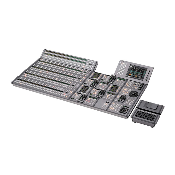
Names and Functions of Parts of the Control Panel Control Panel: Example Configuration 1 (With Standard Transition Modules) The MVS-8000 system control panel standard transition modules used in the comprises a number of modules. transition control block. The following illustration shows a typical 32-button, 4-M/E configuration, with Auxiliary bus control block (page 77) M/E-1 bank... - Page 44 Keyframe control block (page 70) Menu control block (page 81) Key control block (page 58) Device control block (page 62/page 66) Memory card/USB adaptor block (page 82) “Memory Stick”/USB connections block (page 83) Utility/Shotbox control block (page 84) Downstream key control block (page 92) Transition control block (standard type) (page 51) Numeric keypad control block (page 73)
-
Page 45: (With Simple Transition Modules)
Control Panel: Example Configuration 2 (With Simple Transition Modules) The following illustration shows a typical Except for the simple modules, this is the configuration, with simple transition same configuration as in example modules used in the transition control configuration 1. block. - Page 46 Transition control block and Flexi Pad control block (simple type) (page 85) Independent key transition control block (simple type) (page 90) Control panel configuration 2 (right side) (with simple transition modules) Names and Functions of Parts of the Control Panel...
-
Page 47: (With Compact Transition Modules)
Control Panel: Example Configuration 3 (With Compact Transition Modules) The following illustration shows a typical modules used in the transition control configuration, with compact transition block. Transition control block (compact type) (page 96) Control panel configuration 3 (with compact transition modules) Names and Functions of Parts of the Control Panel... -
Page 48: Cross-Point Control Block
Cross-Point Control Block In the cross-point control block, you can All operations except those of the [SHIFT] select the signals to be used in this M/E button are the same as for a module with bank or PGM/PST bank. source name displays. There are also modules without the source name displays shown in the following figure. - Page 49 the M/E bank (or the [DSK3] button in 2 bus, and can be used to select the the PGM/PST bank) is off, then press signal on that bus. the button assigned to the desired Reentry buttons: These allow you to select signal.
- Page 50 c Key bus selection buttons of the source name display, for each source KEY3 button: Press this button, turning it separately. You can set the source name on, to assign the key 1 cross-point display mode and background color in a buttons to the key 3 fill bus.
- Page 51 For details, see “Setting the Assignment of Macro Operation Buttons” in Chapter 19 (Volume 3). Notes For the CCP-6224/6324, [AUX CTRL] is assigned to this button. For details, see “Cross-Point Control Block (CCP-6224/6324) in the AUX Operating Mode” (page 100). POST MCRO (post macro) button: Use this button to set a macro attachment in post macro mode.
-
Page 52: Transition Control Block (Standard Type)
Transition Control Block (Standard Type) In the transition control block, you can common transition and independent key modify the output of the M/E bank or PGM/ transition operations are possible. PST bank, and perform transitions. Both 9 PRIOR SET button 1 Next transition selection buttons 8 Key status display 2 Transition type selection buttons... - Page 53 a Next transition selection buttons In a key transition, the key fades in (for Press these buttons, turning them on, to insertion) or out (for removal). determine what the next transition will NAM (non-additive mix): The current and apply to. new video signals are compared, and BKGD: Next transition changes the the signal with the higher luminance...
- Page 54 c Transition execution section REV (reverse): The wipe proceeds in the Transition indicator: This comprises opposite direction to that when the multiple LEDs, which show the [NORM] button is pressed. progress of the transition. When the VTR/disk recorder/frame Fader lever: Move up or down to carry out memory operation mode is enabled in the transition.
- Page 55 Move the fader lever to the position of keyer. Press one of the [KEY1] to [KEY4] a particular pattern size, and stop it buttons ([DSK1] to [DSK4] in the PGM/ there, then press this button to set the PST bank), turning it on. pattern limit range.
-
Page 56: Flexi Pad Control Block (Standard Type)
n Key snapshot setting buttons corresponding to the button appears in the final program output, the button K-SS (key snapshot): This enables key lights red, and otherwise lights amber. snapshot mode. AUTO TRANS (transition) buttons: K-SS STORE (key snapshot store): To These correspond to keys 1 to 4 from save a key snapshot, hold down this left to right;... - Page 57 1 Mode selection buttons 5 XPT HOLD status display 6 Numeric display 4 UNDO button 2 Bank selection buttons 3 Memory recall section a Mode selection buttons SHOTBOX: To recall or execute a WIPE: To save or recall a wipe snapshot, shotbox, use this in combination with or recall the pattern number of a wipe the buttons of the memory recall...
- Page 58 b Bank selection buttons DME wipe, a bank number, a register BANK0 (bank 0): Assigns the memory number, a transition rate, and so on in up to recall section to bank 0, of registers 1 to four digits. BANK1 (bank 1): Assigns the memory recall section to bank 1, of registers 11 to 20.
-
Page 59: Key Control Block
Key Control Block Each of the M/E banks and the PGM/PST any desired keyer. In this control block, you bank includes four keyers (for keys 1 to 4), can adjust and modify keys. and you can delegate this control block to 3 Key fill/key source selection buttons 2 Key type selection buttons q;... - Page 60 pressing one of the DME channel MATTE FILL: To use a color matte from selection buttons, you can preset the the internal generator as key fill, press DME channel to be used when a DME this button, turning it on. You can wipe is selected as the transition type adjust the color matte using the knobs.
- Page 61 i DME channel selection buttons • When emboss is selected, you can use the dedicated color matte signal for the Press one of these buttons, turning it on, to emboss function. delegate a DME channel to the keyer. • When outline is selected, the signal The number of valid DME channel selected on the key fill bus is used to fill selection buttons depends on the number of...
- Page 62 currently selected keyer, the key of the independent key transition control processed signals are selected for frame block. memory sources 1 and 2. If a DME is o RESIZER button selected on the currently selected (for the MVS-8000G only) keyer, the key fill and key source Enables or disables resizer.
-
Page 63: Device Control Block (Trackball)
Device Control Block (Trackball) The description below of frame memory DME, for wipe pattern position setting, and clip operations applies only to the MVS- for VTR/disk recorder/frame memory clip 8000A/8000G. operation. The device control block is used for three- dimensional transform operations using a 5 MENU button 1 Region selection buttons 3 Trackball... - Page 64 control block. Each button functions as pattern position setting for color follows. background 2 is enabled. (From upper left to right in the above K3: Press this button to enable wipe pattern figure) position setting for key 3 (DSK3). [M/E1] to [M/E3]: DEV1 (device 1) to K4: Press this button to enable wipe pattern DEV3 (device 3) position setting for key 4 (DSK4).
- Page 65 For details, see “Basic Operations” in detent values. Pressing twice in rapid Chapter 11 (Volume 2). succession returns the two-dimensional transformation settings to the defaults. When the VTR/disk recorder/frame c Trackball memory operation mode is enabled The buttons are used for VTR control or When the positioner operation mode is playback of frame memory clips.
- Page 66 When the effect run control mode is enabled By turning the Z-ring, you can run the keyframe effect, independent of the STOP NEXT KF, EFF LOOP, and similar settings in the keyframe control block. Turn clockwise to run the effect in the normal direction, and counterclockwise for the reverse direction.
-
Page 67: Device Control Block (Joystick)
Device Control Block (Joystick) The description below of frame memory All functions of the joystick type device clip operations applies only to the MVS- control block are equivalent to the functions 8000A/8000G. of the trackball type, except that the trackball and Z-ring operations are carried out with the joystick. -
Page 68: Device Control Block (Search Dial)
Move to the right to run the effect in the clip operation, at a speed determined by the normal direction, and to the left for the operating buttons. reverse direction. When the resizer control mode is enabled When the VTR/disk recorder/frame (for the MVS-8000G only) memory operation mode is enabled Move for operations in the x-, y-, and z-... - Page 69 a Timecode display DEV: Assign external devices DEV1 to This shows the current time (CURRENT) DEV12. and the start and stop point timecode values FM CLIP: Assign frame memory clips for the current reference device (START FM1 to FM8. TC, STOP TC). When you press a device Device selection buttons can be set as selection button, the button lights, selecting SBOX buttons or DELAY button in the...
- Page 70 this button is pressed. STB (standby) OFF: When pressed, this When the device the operation applies button flashes amber, and the device to is a VTR/disk recorder, the start selected with the device selection point updated by the setting of the buttons exits from the standby mode.
-
Page 71: Keyframe Control Block
g TIMELINE button REC: When pressed simultaneously with the [PLAY] button, this button lights Press to switch the device selected with the red (the [PLAY] button lights amber), device selection buttons to timeline setting and the image from the selected device mode. - Page 72 1 EDIT ENBL button 4 Duration setting buttons 8 Effect execution direction selection qa AUTO INS button buttons 5 KF LOOP button 0 EFF LOOP button 6 PAUSE button 9 STOP NEXT KF button 2 Edit point 7 Effect execution section specification 3 Editing buttons buttons...
- Page 73 c Editing buttons editing, macro event) is copied. You ALL: Press this button, turning it on, to can also select multiple keyframes or select all keyframes (during macro macro events, and copy them in a editing, all events) in the effect. single operation.
-
Page 74: Numeric Keypad Control Block
h Effect execution direction selection through the keyframes in the specified range. buttons NORM (normal): When this button is lit, f PAUSE button effect execution runs from the first When this button is pressed, a pause is keyframe to the last keyframe. applied to the selected keyframe. - Page 75 1 Mode selection buttons 5 Display 4 Numeric keypad 3 Function selection buttons 2 Region selection buttons a Mode selection buttons You can select more than one region at the EFF (effect): Press to save or recall an same time. effect.
- Page 76 DME1 to DME8: Select a DME channel. +/–/ EFF DISS (effect dissolve): Invert the P-Bus: Select the P-Bus region. sign, negative or positive. GPI: Select the GPI region. When the [SNAPSHOT] button is lit, RTR: Select the router region. applies the effect dissolve attribute to a DEV1 to DEV12: Select the Device 1 to snapshot.
-
Page 77: Fade To Black Control Block
Fade to Black Control Block 3 AUTO button 1 FTB button 2 Preview selection buttons a FTB (fade to black) button PVW, M/E-3 K-PVW, P/P K-PVW) of Press this button to fade to black the the M/E or PGM/PST bank program output of the PGM/PST bank, at corresponding to the pressed button is the set transition rate. -
Page 78: Auxiliary Bus Control Block (For Aux Buses)
Auxiliary Bus Control Block (for AUX Buses) There are also models without the selected All operations except those of the [DEST] source name displays and source name button and [SHIFT] button are the same as displays shown in the following figure. for a model with selected source name displays and source name displays. - Page 79 b Selected source name displays g KEY button These show the name of the currently While this button is held down, you can use selected signal (source) on the bus the cross-point row of buttons to select key corresponding to the delegation button. signals.
-
Page 80: Auxiliary Bus Control Block (For Router Control)
Auxiliary Bus Control Block (for Router Control) Press the [RTR] button, turning it on, to assign the auxiliary bus control block to router control. 7 KEY button 8 2ND button 1 Destination selection buttons qa RTR button 2 Selected source name displays 3 DEST button qs Level selection buttons 5 Source selection... - Page 81 mode, then the description names appear Source [SHIFT] [KEY] Selection here. selection operation 63 to 93 Hold down the c DEST (destination) button [KEY] button, and press the Press this button, turning it on, to display source selection the names of the destinations assigned to button.
-
Page 82: Menu Control Block
k RTR (router) button appear only while the [2ND] button is held down. Press this button, turning it on, to assign the auxiliary bus control block to router j SHIFT button control. While this button is active, the source name l Level selection buttons displays show the shifted signal names. -
Page 83: Memory Card/Usb Adaptor Block
For details on the devices that can be effect, and setup data. connected, consult your Sony representative. b DEVICE connectors There are three USB connectors. Names and Functions of Parts of the Control Panel... -
Page 84: Memory Stick"/Usb Connections Block
USB interface to any of these connectors. Notes For details on the devices that can be connected, consult your Sony Do not power the unit off or remove a representative. “Memory Stick” when the “Memory Stick” status indicator is lit. -
Page 85: Utility/Shotbox Control Block
• Do not attach anything other than the Notes supplied label to the “Memory Stick” • When using a “Memory Stick PRO,” labeling position. high-rate data transfer using parallel • Attach the label so that it does not stick interface is not supported. out beyond the labeling position. -
Page 86: Transition Control Block And Flexi Pad Control Block (Simple Type)
a Bank selection buttons lights orange, and the assigned register Press any of the [BANK1] to [BANK4] name appears. (If the register is empty, the buttons to select a bank of 24 memory recall button goes off.) In the case of a shotbox buttons. - Page 87 qa Numeric display 0 XPT HOLD status display 2 Key transition selection buttons 6 Key status display 1 Transition type selection buttons 3 Transition execution section 5 Pattern limit buttons 4 Wipe direction selection buttons 7 Mode selection buttons 9 UNDO button 8 Memory recall section Shown above is the right-hand type transition control block (with the right-hand fader lever).
- Page 88 Transition Control Block and Flexi Pad Control Block (with INH button) qs INH button Memory recall section UNDO button a Transition type selection buttons You can also assign a function to these You can assign these buttons in setup to any buttons to select whether or not the fader transition type (see “Overall Control Panel levers are used as key frame faders.
- Page 89 c Transition execution section 100% to zero in the second half while the new video is maintained at 100%. Fader lever: Move this vertically to carry WIPE: The current video is replaced by the out a transition. new video, using the wipe pattern When the [KF] button or a transition selected in the Wipe menu.
- Page 90 button, turning it on, enables the the memory recall section for recalling and pattern limit function. executing a macro. f Key status display j XPT HOLD (cross-point hold) status For each of keys 1 and 2, when the key is display inserted, the corresponding ON indicator A bus for which cross-point hold is set...
-
Page 91: Independent Key Transition Control Block (Simple Type)
Independent Key Transition Control Block (Simple Type) The left side of this control block controls In setup you can assign any key to either key 3, and the right side controls key 4. side of this control block. For details, see The control block for key 3 only is “Assigning Keys to the Independent Key described as an example, but the operations... - Page 92 control block lights, and a key 3 key bus cross-point can be selected. • If you press this button, while holding down [TRANS RATE] button in the numeric keypad control block, you can set the independent key transition rate on the control block.
-
Page 93: Downstream Key Control Block
Downstream Key Control Block 1 Key delegation buttons 5 Key source name display/key snapshot buttons 4 Key snapshot setting buttons 2 Independent key transition type selection buttons 3 Independent key transition execution section a Key delegation buttons b Independent key transition type Press one of the [DSK1] to [DSK4] buttons selection buttons to delegate this control block to the... - Page 94 e Key source name display/key SHIFT: When setting is made in the Setup menu to allow a different transition snapshot buttons type for inserting or deleting a key, it is These display the selected source name for possible to display and set the each corresponding keyer.
-
Page 95: Downstream Key/Fade-To-Black Control Block
Downstream Key/Fade-to-Black Control Block 4 Key source name display/key snapshot buttons 3 K-SS button 5 FTB button 7 Preview selection buttons 2 Independent key transition 1 Key delegation 6 AUTO button execution section buttons a Key delegation buttons a) The key bus selection button [KEY3] in the P/P cross-point control block goes off. - Page 96 an auto transition. The transition PST (preset): When this button is pressed, immediately starts, and the button the signal selected on the background B lights amber. When the transition row of the PGM/PST bank is selected completes, the button goes off. on the edit preview bus.
-
Page 97: Transition Control Block (Compact Type)
Transition Control Block (Compact Type) The compact version of the transition Independent key transition operations can control block shown in the following figure also be controlled with the compact has fewer buttons than the standard type. transition control block. 7 PRIOR SET button 1 Next transition selection buttons 6 Key status display 2 Transition type selection buttons... - Page 98 priority after the next transition appears zero in the second half while the new in the key status display. video is maintained at 100%. ALL: Pressing this button turns on a PST (preset) COLOR MIX: In the first preselected set of the [BKGD], [KEY1] transition, the current video is replaced to [KEY4], and [KEY PRIOR] buttons.
-
Page 99: Ccp-6224 2M/E Control Panel
(duration). The transition starts inserted. It also shows the priority (1 to 4) immediately, and the button lights of each key. amber. When the transition completes, g PRIOR (priority) SET button the button goes off. While this button is held down, you can set CUT button: Pressing this button carries the key priority. -
Page 100: Ccp-6324 3M/E Control Panel
3Device control block 2Transition control block (track ball) (compact type) 1 Cross-point control block 4Multifunction Flexi Pad control block a Cross-point control block b Transition control block (compact type) For details of cross-point control block operation, see “Cross-Point Control For details of operations, see “Transition Block”... -
Page 101: Cross-Point Control Block (Ccp-6224/6324) In The Aux Operating Mode
2Transition control block (compact type) 1 Cross-point control block 4Multifunction Flexi Pad control block 3Device control block (track ball) a Cross-point control block c Device control block (track ball) For details of operations, see “Cross-Point For details of operations, see “Device Control Block”... - Page 102 AUX cross-point buttons 2AUX CTRL (AUX control) button AUX CTRL (AUX control) button 3DEST (destination) button 1 AUX control block 4KEY button 5AUX DSPLY (AUX display) button 6A/B bus control block 7Source/bus name displays a AUX control block AUX delegation buttons: These select the This selects the AUX bus and the assigned AUX bus.
-
Page 103: Multifunction Flexi Pad Control Block
can make the rightmost button a of the key source signals assigned to the [SHIFT] button, in which case each AUX cross-point buttons, and they are now button can be used to select two video/ selectable. key source signals. e AUX DSPLY (AUX display) button When one of the DME 1V/K to 4V/K This switches the source name displays to buses is selected with the AUX... - Page 104 2 EDIT ENBL button 4 Alphanumeric display 7 Adjustment knobs 1 Mode selection buttons 6 Adjustment knob displays 3 Region selection buttons 5 Memory recall section a Mode selection buttons KEY ADJ (key adjust): Press this to carry EFF (effect): Press this to carry out effect out key adjustments and set modifiers.
- Page 105 c Region selection buttons d Alphanumeric display These select the function block to which This shows the selected region name or operations apply. register number, and entered numeric When the mode selection button selection is values. EFF/SNAPSHOT/SHOT BOX/MCRO, e Memory recall section you can select multiple region selection This comprises 16 LCD buttons, each with buttons simultaneously.
-
Page 106: Basic Menu Operations
Basic Menu Operations Menu Organization Operations on the MVS switcher system make frequent use of menu operations. This section describes the menus and their interrelationships. You can also display menus on an external monitor, and use a mouse. The menu operations using a mouse are basically the same as the menu control block operations described here, with mouse clicks in place... -
Page 107: Accessing Menus
page 107). Accessing Menus Depending on the button, this may display a fixed page or the page selected You can use any of the following methods last time you accessed the menu. • Press the menu page selection button at to access a menu, and the initially displayed the top left of the menu display. - Page 108 Buttons Menus Function Device Settings for external device Chapter 12 (Volume 2) operation MCRO Macro Macro register settings Chapter 16 (Volume 2) Key Frame Keyframe settings Chapter 13 (Volume 2) FRAME Effect Keyframe effect register settings Chapter 13 (Volume 2) SNAP Snapshot Snapshot register settings...
- Page 109 Transition control block (standard type, compact type) Buttons Menus • M/E-1, 2, 3 >Key1 >XX page 203 KEY1 (DSK1) • PGM/PST >DSK1 >XX • M/E-1, 2, 3 >Key2 >XX KEY2 (DSK2) • PGM/PST >DSK2 >XX • M/E-1, 2, 3 >Key3 >XX KEY3 (DSK3) •...
- Page 110 a) The menu to be recalled depends on the setup of the key assignment. Flexi Pad control block (standard type) Buttons Menus WIPE M/E-1, 2, 3, PGM/PST >Wipe >Main Pattern page 277 M/E-1, 2, 3, PGM/PST >DME Wipe >XX page 334 SNAPSHOT Snapshot >Snapshot >XX Chapter 14...
- Page 111 Numeric keypad control block Buttons Menus SHOTBOX Shotbox >Register >Store/Recall Chapter 15 (Volume 2) MCRO Macro >Register >XX Chapter 16 (Volume 2) Misc >Transition page 165 TRANS RATE STORE RCALL Chapter 13 Key Frame >Region Select (Volume 2) a) The menu recalled depends on which of the M/E-1 to M/E-3 banks and PGM/PST bank the numeric control block is delegated to.
- Page 112 Auxiliary bus control block Buttons Menus Color Bkgd1 signal assigned Color Bkgd >Color Bkgd1 page 426 button Color Bkgd2 signal assigned Color Bkgd >Color Bkgd2 button CCR1 signal assigned button CCR >CCR1 >XX page 452 CCR2 signal assigned button CCR >CCR2 >XX Device control block (trackball or joystick) Buttons Menus...
- Page 113 Transition control block and Flexi Pad control block (simple type) Buttons Menus KEY1 (DSK1) • M/E-1, 2, 3 >Key1 >XX page 203 • PGM/PST >DSK1 >XX KEY2 (DSK2) • M/E-1, 2, 3 >Key2 >XX • PGM/PST >DSK2 >XX WIPE • M/E-1, 2, 3 >Wipe >Main Pattern page 277 •...
-
Page 114: Displaying A Menu
Multifunction Flexi Pad control block Buttons Menus KEY ADJ > KEY1 page 203 M/E1, 2, 3 >Key1 >xxx PGM/PST >DSK1 >xxx KEY2 M/E1, 2, 3 >Key2 >xxx PGM/PST >DSK2 >xxx KEY3 M/E1, 2, 3 >Key3 >xxx PGM/PST >DSK3 >xxx KEY4 M/E1, 2, 3 >Key4 >xxx PGM/PST >DSK4 >xxx M/E-1 >Key1, 2, 3, 4 >Type... -
Page 115: Interpreting The Menu Screen
The M/E-1 >Key1 >Type menu appears in the menu display as follows. 5 Status area qs b (previous) button and B (next) button 6 Function button area 2 Menu page number button 7 Parameter group button 1 Menu title 0 Keyframe status button qa Default recall button 4 HF buttons... - Page 116 b Menu page number button e Status area This shows the menu screen page number. This shows the status of the settings items When you press this button, the top menu controlled by the selected menu. window (see page 125) appears. You can An orange frame appears around the enter the page number for the desired menu, parameter area relating to the displayed...
-
Page 117: Menu Operations
i Previous page button Menu Operations This shows the page number of the previously displayed menu screen. Press it The method of menu operation is basically to go back to that page. When the indication the same when using a mouse with an [Parent] appears, this displays the parent external monitor, but with mouse clicks in directory. - Page 118 Lit pale blue: The function is enabled, and Setting parameters the parameters can currently be adjusted with the knobs. Lit orange: The function is enabled. Lit purple: Execution button. Pressing the mark button immediately executes the function. (Example: [Auto Start] This marking on a function button indicates button in the Chroma Adjust menu) that there are parameters which can be...
- Page 119 This returns the settings within the This returns the knob parameter value function grouping to the default state, to the default state, and the [Default and the [Default Recall] button goes Recall] button goes off. off. Notes Notes • In the following table, “Menus allowing a return to default settings,”...
- Page 120 Top menu selection button VF number Menu number Menu name name (HF number) M/E2 1210-series Key1 1220-series Key2 1230-series Key3 1240-series Key4 1250-series Wipe 1260-series DME Wipe 1270-series Misc M/E3 1310-series Key1 1320-series Key2 1330-series Key3 1340-series Key4 1350-series Wipe 1360-series DME Wipe 1370-series...
- Page 121 Top menu selection button VF number Menu number Menu name name (HF number) 4110-series Edge 4120-series Video Modify 4131 Freeze 4141 Non-Linear 4150-series Light/Trail 4160-series Input/Output 4170-series Enhanced Video Modify GLB EFF 4210-series Ch1–Ch4 4220-series Ch5–Ch8 KEY FRAME (HF3) 6113 Path a) Menu to return to the default settings for particular functions or for particular knob parameters (for the relevant knob parameters, see page 120)
- Page 122 Knob parameters to which default recall does not apply Menu name Button name Knob Parameter Menu number 1116 Transition [Wipe] in <ON Transition Type> Transition group Rate Pattern [Wipe] in <OFF Transition Type> Transition group Rate Pattern [Key Blink] and [Edge Blink] in Blink Rate <Blink>...
-
Page 123: Operation With A Mouse
Knob parameters subject to restriction on default recall Menu number Menu name Button name Knob Parameter Transition >DME [Position] 1116.3 Wipe Adjust Edge Direction [Position] Position H 1154.1 >Matte Adjust Position V Main Modify [Position] in the <Position> group 1155 Main Modify [Position] 1155.1... - Page 124 b Max./min. (maximum/minimum) • Position the cursor over the knob setting parameter button for which you want to value indication adjust the value, then click the left mouse This shows the maximum and minimum button to open the numeric keypad settings of the parameter.
- Page 125 Keyboard window space, \, /, :, ;, , (comma), . (dot), <, >, Notes *, ?, ", | Except when changing source names, the following characters cannot be used. 4 BS button 1 Item display 2 Input string 3 Close button qd Line feed button 7 Space button...
- Page 126 j Left button MS-DOS does not distinguish case in filenames, and therefore you are This moves the cursor one character to the recommended to enter filenames in capital left in the input string. letters. k Right button f Shift button This moves the cursor one character to the This selects the characters on the shift side right in the input string.
- Page 127 a Top menu selection buttons Shutting down the menus These are the same as the top menu selection buttons in the menu control block. In the menu screen, press the menu Pressing one of these buttons closes the top page number button to open the top menu window and displays the selected menu window.
- Page 128 1Color palette buttons 2Operation buttons 3Color display 4Numeric keypad a Color palette buttons color palette button is set to the default Press one of these to enter the color. corresponding color in the display. c Color display By default the following settings are This shows the setting color, and the available.
-
Page 129: Switching Between The Main Menu Site And Subsidiary Menu Site
Switching Between the Main Menu Site and Subsidiary Menu Site For menu transitions, you can store two separate versions in the main and subsidiary menu sites. By switching sites, and pressing the b button and the B button you can trace the In the [Group Select] box, select the history in each menu. - Page 130 Press [Yes]. This deletes the settings. To register a menu on a button You can register 15 buttons in one group. In the Home >Favorites >Shortcut menu, press [Button Edit]. With the cursor, select the group name (in this case a blank button) for the operation.
- Page 131 To change the button color, press To execute a menu macro with a button [Color Set]. See “Recalling a Menu Macro Register and Button color samples appear. Executing a Menu Macro” in Chapter 16 (Volume 2). Press the desired color. This completes the assignment of the menu to the button.
-
Page 132: Chapter 3 Signal Selection And Transitions
Chapter 3 Signal Selection and Transitions... -
Page 133: Video Processing Flow
Video Processing Flow The switch from the current video stream (appearing on the corresponding program monitor) to a new video stream is referred to as a transition. The following illustration shows the flow of operations for carrying out a transition on an M/E bank or the PGM/PST bank. Video Processing Flow... - Page 134 Select current background video (page 134) Select next transition (page 144) Background Keys 1 to 4 Select new background video (page 134) Make key settings (page 195) Select transition type (page 144) DME wipe Super Preset color Wipe Make wipe settings (page 277) Make DME wipe settings (page 334)
-
Page 135: Signal Selection
Signal Selection You carry out signal selection with the cross-point buttons in the cross-point control block of each M/E bank or the PGM/PST bank, and the buttons in the auxiliary bus control block. The number of buttons in each cross-point row may be 16, 24, or 32, but here the description is of the 32-button case as an example. -
Page 136: Basics Of Signal Selection
Basics of Signal Selection Each of the M/E banks, PGM/PST bank and auxiliary bus control block has 32 cross-point buttons and three reentry buttons (four in the case of the auxiliary bus control block). These buttons are identified by numbers common to all of the banks and block, and a signal is assigned to each number. - Page 137 Bank Bus name Cross-point Delegation operation button row M/E-1, Background A – Background A bus M/E-2, M/E-3 Background B – Background B bus Key 1 bus Key 1 row Turn off the [KEY3] button Key 2 bus Key 2 row Turn off the [KEY4] button Key 3 bus Key 1 row...
- Page 138 Bank Bus name Cross-point Delegation operation button row Auxiliary AUX1 to AUX48 buses 1st row, 2nd row Turn on the appropriate bus control buttons in accordance with MONITOR 1 to block the signal assignment MONITOR 8 buses made in the Setup menu. Frame memory source 1 and frame memory source 2 buses...
-
Page 139: Aux Panel-Less Function
a) Dual background bus mode (see below) can be selected. Dual background bus mode In this mode, the shifted signal on the background A row can be selected on the key 1 row, and the shifted signal on the background B row can be selected on the key 2 row. -
Page 140: Signal Assignment And Selection
Signal Assignment and Selection Assigning signals to buttons Each of the 32 cross-point buttons and reentry buttons has a corresponding button number, to which you assign a signal. In addition to the signals input to the PRIMARY INPUTS 1 to 80 connectors (1 to 34 connectors for the MVS-8000SF/8000ASF/8000GSF) on the rear panel of the switcher, you can also select signals generated within the switcher. - Page 141 Notes On the MVS-8000A/8000G, you can use the rightmost button (number 32) as a [SIDE FLAG] button. In this case, the shift button moves one to the left, to number 31, and the button numbers are offset by one. For details of the [SIDE FLAG] button, see “Cross-Point Settings (Xpt Assign Menu)”...
- Page 142 When the [2ND] button is lit Different buses can be assigned to the 1st-row buttons and 2nd-row buttons. When the 32nd button is set as a shift button, the 1st-row buttons and 2nd-row buttons both have the following button numbers. Auxiliary bus control block button numbers ([2ND] button lit) Button Number when the shift...
-
Page 143: Signal Name Display
For details of the setting, see “Cross-Point Settings (Xpt Assign menu)” in Chapter 19 (Volume 3). Notes • For details of audio mixers that can be connected, contact your Sony service or sales representative. • When the signal is switched with a snapshot, keyframe, and so on, the audio mixer is not linked. - Page 144 • The source name displays in the cross-point control block and auxiliary bus control block show the source names of the video signals assigned to numbers 1 to 31. • To display the source names for numbers 32 to 62, press the [SHIFT] button to the right of the source name displays.
-
Page 145: Transitions
Transitions Selecting the Next Transition To execute a transition, it is first necessary to decide how the image will be changed as a result of the transition. This selection is carried out using the next transition selection buttons (see page 52) in the transition control block of each M/E or PGM/PST bank. - Page 146 Notes This transition type is not available for an independent key transition. Super mix In this dissolve, the current video is maintained at 100% output for the first half of the transition as the new video is mixed while increasing progressively to 100%, then the current video is progressively reduced from 100% to zero in the second half with the new video maintained at 100% output.
- Page 147 Clip transitions Linked to a mix (dissolve) or wipe transition, a frame memory clip (movie) is played back. Notes The clip transition function is only supported on the MVS-8000A/8000G. A cut switches instantaneously from the current video to the new video. When the next transition is a key transition, the key cuts in or out instantaneously.
-
Page 148: Procedure For Basic Transition Operation
Procedure for Basic Transition Operation The positions of the principal buttons used for basic transition operation are as follows. 1 2 3 4 1 2 3 4 1 2 3 4 1 2 3 4 BKGD KEY1 KEY2 KEY3 KEY4 Next transition SUPER PRIOR... - Page 149 For the transition to change the key priority, set the priority for after the transition. For details of the key priority setting operation, see “Key Priority Setting” (page 150). Select the new video used for the transition. • In the background B row of cross-point buttons, select the new background video.
- Page 150 – When carrying out a cross fade in some DME wipes (for example, “picture in picture”) – When executing a preset color mix in two-stroke mode • For details of audio mixers that can be used, contact your Sony service or sales representative. Procedure for Basic Transition Operation...
-
Page 151: Key Priority Setting
Key Priority Setting If a number of keys are already inserted in the current video, you can check or change the key priority, that is to say, the order in which the keys are overlaid. When a key priority ([KEY PRIOR]) is selected as the next transition, you can also change the key priority in the new video. - Page 152 Next transition selection buttons KEY PRIOR button PRIOR SET button Transition control block (standard type) Changing the currently inserted key priority If the next transition selection button [KEY PRIOR] is on, press another next transition selection button to turn the [KEY PRIOR] button off. (When the [KEY PRIOR] button is on, the transition control block switches to the mode for changing the key priority for after the transition.) Holding down the [PRIOR SET] button, press the one of the next transition...
-
Page 153: Setting The Key Priority By A Menu Operation
Changing the key priority for after the transition When executing a transition, turning on the next transition selection button [KEY PRIOR] causes the keys to be rearranged based on the set priority. To set the key priority for after the transition, use the following procedure. In the transition control block, hold down the [PRIOR SET] button and press the [KEY PRIOR] button to turn it on. - Page 154 For each of <Priority1>, <Priority2>, <Priority3>, and <Priority4>, select a key, to determine the key priority sequence. The keys are inserted in the key priority sequence with priority 1 at the front. Priority 1 Priority 2 Priority 3 Priority 4 Notes It is not possible to select the same key for two or more priority numbers.
-
Page 155: Display Of The Key Output Status And Key Priority
Display of the Key Output Status and Key Priority You can check whether keys are currently output, and the key priority setting, using the key status display in the transition control block of the M/E or PGM/ PST bank. The display is above the next transition selection buttons [KEY1] to [KEY4] ([DSK1] to [DSK4] buttons in the PGM/PST bank). -
Page 156: Selecting The Transition Type By A Menu Operation
Selecting the Transition Type by a Menu Operation You can also select the required transition type by a menu operation. In the M/E or PGM/PST menu, select first VF7 ‘Misc,’ then HF1 ‘Transition.’ The Transition menu appears. Select the required transition type in the <Transition Type> group. The parameter settings can now be adjusted with the knobs according to the selected transition type. -
Page 157: Super Mix Settings
Super Mix Settings You can set the output levels of the current and new video signals at the mid- point of the transition, in the range 0 to 100%. Notes This transition type is not available for an independent key transition. In the M/E or PGM/PST menu, select first VF7 ‘Misc,’... -
Page 158: Color Matte Settings
Color Matte Settings You can specify the color matte by luminance, saturation, and hue values. Also, in place of a color matte you can use an image selected on the utility 2 bus. Notes • This transition type is not available for an independent key transition. •... - Page 159 When a key is inserted Key fades out When a key is selected as the next transition When no key is selected Key fades in Preset color mix (transition including key) By means of a Setup menu setting, it is possible to preserve the key state while carrying out the color matte mix.
- Page 160 When “Flat Color” is selected, turn the knobs to adjust the color matte. Knob Parameter Adjustment Setting values Luminance Luminance 0.00 to 100.00 Saturation Saturation 0.00 to 100.00 359.99 to 0.00 Color Matte Settings...
-
Page 161: Executing A Transition
Executing a Transition There are two modes of executing a transition: an auto transition by button operation or a manual transition using the fader lever. It is also possible to combine both methods, taking control with the fader lever of an auto transition which has partly completed, or complete a transition started with the fader lever as an auto transition. -
Page 162: Setting The Transition Rate
When the transition is completed, all of the LEDs go off. Setting the Transition Rate There are three ways of setting the transition rate: using the Flexi Pad control block, Multifunction Flexi Pad control block or numeric keypad control block to enter a numeric value, or using the Misc menu to access the Transition menu for the M/E or PGM/PST bank. - Page 163 Frame display mode: Values are shown as from 0 to 999 frames. In this display mode, a value entered in timecode input mode is converted for display as a number of frames. Timecode display mode: Values are shown as timecode values, consisting of seconds and frames.
- Page 164 • Enter a value of up to three digits. • To cancel the entry, press any of the six buttons in the leftmost column ([WIPE], [DME], ...) or the [TRANS RATE] button. Press the [ENTR] button. This confirms the entry, and the new setting appears in the transition control block display.
- Page 165 Press the [ENTER] button. This confirms the entry, and the selected region name and the set transition rate appear in the numeric keypad control block display. The transition control block display of the same bank (M/E or PGM/PST) also shows the setting. To enter a difference from the current value After pressing the [+/–] button, enter the difference and press the [TRIM] button.
- Page 166 Press the [TRANS] button. You can now set the M/E-1 block background transition rate. Watching the alphanumeric display, enter the transition rate you want to set with the memory recall section button. If required, press the [TC] button to switch the input mode (frame count input or timecode input).
-
Page 167: Pattern Limit
For more details, see “Displaying a List of Transition Rates and Changing the Settings” (page 440). Pattern Limit When a wipe or DME wipe pattern is selected for the transition, you can specify the range of movement of the wipe pattern through the course of the transition, for each bank independently. - Page 168 TRANS PVW button PTN LIMIT button LIMIT SET button Transition control block (standard type) Setting the pattern limit with the fader lever Move the fader lever to the position corresponding to a particular pattern size. • First make sure that the [PTN LIMIT] button is off. •...
- Page 169 Turn the knobs to adjust the following parameters. Knob Parameter Adjustment Setting values Pattern Limit Pattern limit 0.00 to 100.00% a) 0.00%: Executing the transition does not change the video output at all. b) 100.00%: The transition is the same as when no pattern limit is set, but the cross-point button selections of the background A and B buses do not interchange when the transition completes.
-
Page 170: Executing An Auto Transition
carried out. Moving the fader lever even a little synchronizes the fader lever position with the transition state, and you can move the fader lever either in the forward direction or in the reverse direction. Depending on the Setup settings, the transition may be executed at the instant you press the [PTN LIMIT] button, and the button goes off. -
Page 171: Executing A Transition With The Fader Lever (Manual Transition)
Fader lever AUTO TRANS button CUT button Transition control block (standard type) To execute a transition on the M/E or PGM/PST bank by a button operation, use the following procedure in the transition control block. To carry out an instantaneous cut transition: Press the [CUT] button. To carry out a gradual transition: Press the [AUTO TRANS] button. -
Page 172: Combinations Of Auto And Manual Transitions
To pause a partly executed transition: Stop moving the fader lever. To resume a paused transition: Resume moving the fader lever. Combinations of Auto and Manual Transitions Using the [AUTO TRANS] button, the [CUT] button, and the fader lever, use the following procedures. -
Page 173: Fader Lever Operation In Bus Fixed Mode
Once the fader lever is moved to this position, the non-sync state ends, and the next transition (direction shown by the arrow) is possible. Manual transition completed as auto Manual transition completed as transition when moving the fader auto transition when moving the lever upward: Top two LEDs light. - Page 174 Flip-flop mode Bus fixed mode Fader lever Buttons lit Flip-flop mode and bus fixed mode In the bus fixed mode there is a fixed relationship between the position of the fader lever and the signal output on each bus. Depending on the direction of the transition, the fader lever must therefore always be moved in a particular direction, as shown in the following table.
-
Page 175: Transition Preview
Transition Preview With the preview output of the M/E banks and PGM/PST bank, you can check the effect of a transition in advance. To carry out a transition preview, press the [TRANS PVW] button in the transition control block. Notes In multi-program mode, DSK mode or bus fixed mode (page 172), it is not possible to carry out a transition preview. - Page 176 Transition Preview Switcher setup Panel setup mode (Transition menu) (Operation >Custom Button <Transition Preview> group menu) <Trans Pvw> group Hold Normal Hold One Time One Time – Notes • During a transition, whether executed with the [AUTO TRANS] button or the fader lever, it is not possible to press the [TRANS PVW] button.
-
Page 177: Independent Key Transitions
Independent Key Transitions What is an independent key transition? In addition to common transitions, it is possible to carry out independent transitions on the keyers of the M/E banks and PGM/PST bank. These are called “independent key transitions.” By carrying out an independent key transition in combination with a common transition, different transition types can be used for the background and keys. - Page 178 The key is deleted, Wipe and mix even if the (dissolve) are independent key carried out transition has not simultaneously. completed. Deleting a key with simultaneous transitions Inserting a key with simultaneous transitions: With the key not inserted, it is inserted simultaneously with the two transitions. If the common transition or independent key transition ends first, the other continues to completion.
- Page 179 Example: When the independent key transition [AUTO TRANS] button is pressed later The key is deleted, even if the Common transition Independent key independent key (wipe) start transition (mix) start transition has not completed. Time offset execution with the key inserted Time offset execution with the key not inserted: With the key not inserted, it is inserted with the transition whose [AUTO TRANS] button is pressed first.
-
Page 180: Basic Independent Key Transition Operations
Basic Independent Key Transition Operations Key source name display/key snapshot buttons Key delegation buttons Independent key transition type selection buttons Independent key transition execution section Independent key transition control block (standard type) To set independent transitions for the keyers on the M/E or PGM/PST bank, use the independent key transition control block. - Page 181 For details of the wipe settings, see “Wipe Settings for Independent Key Transitions” (page 303). For details of DME wipe settings, see “DME Wipe Settings for Independent Key Transitions” (page 345). Execute the transition. To insert or delete the key gradually with a mix or wipe transition: Press the [AUTO TRANS] button.
-
Page 182: Setting The Independent Key Transition Type By A Menu Operation
Independent key transition operations when using the CCP-6224/ 6324 Control Panel Independent key transition execution section Transition control block (compact type) To carry out an independent key transition, press the corresponding button in the independent key transition execution section of the transition control block. The color of the button shows the status as follows. -
Page 183: Setting The Independent Key Transition Rate
If, in the Setup menus, you set insertion/deletion as independent modes, make the settings for insertion in the <On Transition Type> group, and the settings for deletion in the <Off Transition Type> group. Setting the Independent Key Transition Rate There are two ways of setting the transition rate: using the Flexi Pad control block, Multifunction Flexi Pad control block or numeric keypad control block to enter a numeric value, or using the Key menu to access the Transition menu for the M/E or PGM/PST bank. - Page 184 Setting the independent key transition rate in the numeric keypad control block Notes You cannot use the numeric keypad control block to set the transition rate for a simple transition. In the numeric keypad control block, hold down the [TRANS RATE] button, and in the independent key transition control block, press the delegation button [KEY1] to [KEY4] ([DSK1] to [DSK4] in the PGM/PST bank) for the key for which you want to set the transition rate.
- Page 185 Press the [TRANS SEL] button in the memory recall section. You can select the type of transition for which to set the rate. Press the [KEY1] button. This enables setting of the independent key transition rate for M/E-1 key1. Watching the alphanumeric display, enter the transition rate you want to set with the memory recall section button.
- Page 186 Displaying the independent key transition rates in a menu and changing the settings For each of the M/E and PGM/PST banks, you can also display the transition rate, independent key transition rate and fade-to-black transition rate, and change the settings. For more details, see “Displaying a List of Transition Rates and Changing the Settings”...
-
Page 187: Fade To Black
Fade to Black The PGM/PST bank provides a fade-to-black function, controlled with the [FTB] button in the fade to black control block. Notes In multi-program mode or DSK mode, it is possible to carry out a fade-to-black on a number of programs simultaneously. You can also make a Setup menu setting such that a fade-to-black does not apply to particular programs. -
Page 188: Setting The Fade To Black Transition Rate
During the transition, the [FTB] button lights amber. When the transition completes (the video is completely black), the button lit color changes to red. Setting the Fade to Black Transition Rate Setting the fade to black transition rate In the PGM/PST menu, select first VF7 ‘Misc,’ then HF1 ‘Transition.’ The Transition menu appears. -
Page 189: Simple Transition
Simple Transition Basic Operations for Simple Transitions Key transition selection buttons Key status display Transition type selection buttons Transition execution section Transition control block (simple right-hand type) Notes The simple transition control block cannot be installed in the CCP-6224/6324 Control Panel. Carrying out a transition using a simple-type transition control block With the background A row of cross-point buttons in the cross-point... - Page 190 Using one of the following methods, select the way in which the transition will affect the image. Use a combination of the transition type selection buttons ([MIX], [NAM], [WIPE] and [DME]) and the next transition selection buttons ([KEY1] and [KEY2]). For an overview of the mix, NAM, wipe, and DME wipe transition types, see “Transition Types”...
-
Page 191: Display Of The Key Output Status And Key Priority
For details of the settings, see the following sections: Super mix: “Super Mix Settings” (page 156) Preset color mix: “Color Matte Settings” (page 157) Wipe: “Basic Procedure for Wipe Settings” (page 277) DME Wipe: “Basic Procedure for DME Wipe Settings” (page 334) Clip transition: “Clip Transition Operations”... -
Page 192: Independent Key Transitions With A Simple Transition Module
• The necessary settings have been made in a Setup menu to enable the split fader (See “Settings Relating to Video Switching (Transition Menu)” in Chapter 20 (Volume 3).) • A background is selected for the next transition. • For the transition type, [MIX] or [NAM] is selected. Split fader operation The two halves of the split fader lever correspond to the buses as follows. - Page 193 Key 3 control block Key 4 control block Independent key transition execution section Independent key transition type selection buttons The functions of the key 3 control block and key 4 control block are the same. Independent key transition control block (simple type) Carrying out a transition using a simple-type independent key transition control block Select the transition type for key 3 or key 4 using the independent key...
- Page 194 If, in the Setup menus, you set insertion and deletion as independent modes, make the settings for the next transition in the independent key transition control block. Separate settings are required both when inserting a key and when deleting it. For example, with the key not inserted, if you select the transition type and carry out a transition, this will be the setting when inserting a key.
- Page 195 Simple Transition...
-
Page 196: Chapter 4 Keys
Chapter 4 Keys... -
Page 197: Overview
Overview A key is an effect in which a part of the background image is replaced by an image or superimposed text. The signal determining how the background is cut out is termed “key source,” and the signal that replaces the cut-out part is termed “key fill.”... - Page 198 quality, but means that the part of the key fill signal which is not to be inserted must be completely black, or it will color the background. You set the clean mode with the Type menu of the respective keyer. (See “Setting the key type in a menu”...
-
Page 199: Key Modifiers
Key wipe pattern key This uses the wipe pattern selected for an independent key transition as the key source. Note on wipe pattern modifiers In a wipe pattern key or key wipe pattern key, you can apply various modifications, depending on the pattern used, and the modifiers in common with a wipe. - Page 200 Name Effect Image Drop This applies a border below and to the right border for example, of the key. You can adjust the border width, position, and density. Shadow This applies a shadow below and to the right for example, of the key. You can adjust the shadow width, position, and density.
- Page 201 Key drop ON mode: The key fill/key source position moves downward by eight scan lines or four scan lines. When a drop border or shadow is selected, it is possible to apply a border to the top edge of the key. Key drop OFF mode: The key fill/key source position does not move.
-
Page 202: Key Memory
Key mask and background mask There are two types of mask: a key mask and a background mask. Key mask: This masks out a part of the key, which will result in the background appearing. Background mask: This masks out a part of the background, which will result in the key fill appearing. -
Page 203: Key Default
However, in the case of a chroma key, it excludes color cancel, Y balance, foreground CCR, window, and shadow.) Full mode: All settings except transition (the same parameters as simple mode, Fine Key, key modifiers, main and sub mask settings, chroma key detailed settings, and so on) For the settings for these modes, see “Settings Relating to Keys, Wipes, Frame Memory and Color Correction (Key/Wipe/FM/CCR Menu)”... -
Page 204: Key Setting Operations Using Menus
Key Setting Operations Using Menus There are two ways of making key settings: either using menus, or using the key control block or the Multifunction Flexi Pad control block. This section describes basic procedures for making key settings using the menus, taking the M/E-1 >Key1 menu as an example. -
Page 205: Key Type Setting
Key Type Setting Setting the key type in a menu In the M/E-1 >Key1 menu, select HF1 ‘Type.’ The Type menu appears. In the <Key Type> group, select the key type. Luminance: luminance key Linear: linear key Chroma: chroma key Color Vector: color vector key Wipe Pattern: wipe pattern key Key Wipe Pattern: key wipe pattern key... - Page 206 • When a luminance key or linear key is selected Knob Parameter Adjustment Setting values Clip Reference level for generating the +109.59 to –7.31 key signal Gain Key sensitivity –100.00 to +100.00 Density Key density 0.00 to 100.00 Filter Filter coefficient 1 to 9 a) Setting this value to 1, produces the “through”...
-
Page 207: Chroma Key Composition
To invert the black and white sense of the key source: Press [Key Invert], turning it on. To adjust the horizontal position or key source width for a luminance key, linear key, or chroma key: Press [Key Position], turning it on, and set the parameters. -
Page 208: Chroma Key Adjustments
Select [Chroma Adjust]. The Chroma Adjust menu appears. Carry out auto chroma key adjustments. Also carry out manual adjustments if necessary to obtain an optimum chroma key image. In the <Mix Mode> group, select [Normal Mix] or [Additive Mix] depending on the desired type of chroma key composition. When using an additive mix for chroma keying, the (typically blue) background parts of the foreground video must be converted to black. - Page 209 Color cancel If the foreground image includes shades of the background color, turn this function on to remove the color from the foreground image. Chroma key window You can adjust the range over which the key signal is determined as matching the specified hue.
- Page 210 You can use the Y balance function independently on the key signal for the composition and the key signal for the color cancel function. When applied to the key signal for the composition, this produces the foreground with the color cancel effect applied.
- Page 211 a) The setting ranges depend on the signal format, screen aspect ratio, and size settings. Select [Auto Start] in the <Auto> group. This executes an auto chroma key based on the color specified by the sample selector, and displays the composite image on the monitor. Making key active adjustments When the key active function is on, the composite image is output to the monitor, and you can watch the monitor while manually adjusting the keying.
- Page 212 Set [Key Active] on. The chroma key composite image now appears in the monitor. Making key signal adjustments for color cancel When the color cancel function is set on, you can adjust the key signal for color cancel. In the <Color Cancel> group of the Chroma Adjust menu, set [Color Cancel] on.
- Page 213 • When setting [Y Balance] on and adjusting the ratio in which Y balance is added to the color cancel key Knob Parameter Adjustment Setting values Mixture Ratio of Y balance key 0.00 to 100.00 Adjusting the window Setting the window function on allows you to adjust the detection range used to determine the key signal.
-
Page 214: Selecting Key Fill And Key Source
less than a certain luminance are treated as shadows, there is no effect on cutting out of the foreground. In the Chroma Adjust menu, set [Shadow] on. Adjust the following parameters. Knob Parameter Adjustment Setting values Luminance Reference luminance for shadows 0.00 to 100.00 Gain Shadow key gain –100.00 to +100.00... - Page 215 The Type menu appears. In the <Key Fill> group, select either of the following for use as key fill. Key Bus: signal selected on the key 1 fill bus Matte: signal from the dedicated color matte generator If you selected [Key Bus] in step 2, select the key fill signal on the key 1 row in the cross-point control block.
- Page 216 cross-point control block key 1 row, select the key source signal. Alternatively, hold down the key delegation button in the transition control block and press a cross-point button in the key 1 row to select the key source signal. Notes •...
- Page 217 In the <Target> group, press [Source]. In the <Key Source> group, select the key source selection mode (Self, Auto Select, or Split). See step 5 in “Selecting Key Fill and Key Source” (page 214). If you selected [Split], using any of the following methods, select the key source signal.
- Page 218 This selects the key fill signal. Carrying out a color mix for key fill When [Matte] is selected for key fill, you can combine color 1 and color 2. For the combination, you can use not only a key wipe generator pattern, but also the dedicated pattern for key edge color mix.
-
Page 219: Key Edge Modifications
Knob Parameter Adjustment Setting values Saturation Saturation 0.00 to 100.00 359.99 to 0.00 To interchange color 1 and color 2, press the [Color Invert] button, turning it on. Key Edge Modifications To modify the key edge of key 1 on the M/E-1 bank, use the following procedure. - Page 220 a) In the “4H mode” and when [Fine Key] (page 221) is on, the setting value range is 0.00 to 4.00. b) When a wipe pattern key or key wipe pattern key is selected as the key type • Separate edge on The left, right, top, and bottom border or outline widths can be adjusted independently.
- Page 221 Knob Parameter Adjustment Setting values Density 0.00 to 100.00 Density a) The Density adjustment only affects the key edge. This can be adjusted separately from Key Density, and if Key Density is set to 0.00, the embossed edge effect only can be applied.
- Page 222 When emboss is selected for the edge type, adjust the color in the <Emboss Fill> group. To adjust matte 1 press [Matte1], and to adjust matte 2 press [Matte2], then adjust the following parameters. Knob Parameter Adjustment Setting values Luminance Luminance 0.00 to 100.00 Saturation...
- Page 223 • When applying a border to the key edge, enabling the [Fine Key] function halves the border width setting range. To fix key fill and key source in key drop off mode In the Edge menu, press [Key Delay Mode]. The Key Delay Mode menu appears.
- Page 224 patterns (standard wipe patterns 1 to 24) displayed in the Mix Pattern Select menu, you can adjust the following parameters. Knob Parameter Adjustment Setting values Size Pattern size 0.00 to 100.00 Soft Softness of pattern edge 0.00 to 100.00 Adjust color 1 and color 2. To adjust color 1 press [Color 1], and to adjust color 2 press [Color 2], turning it on respectively, and adjust the following parameters.
- Page 225 • When turning [Angle] on in the <Rotation> group and inclining the pattern Knob Parameter Adjustment Setting values Angle Angle of pattern rotation –100.00 to +100.00 a) See page 292. • When turning [Speed] on in the <Rotation> group and rotating the pattern at a constant speed Knob Parameter...
-
Page 226: Masks
Key Edge Pattern: Use a color mixing pattern for key edge. You can change this pattern by pressing [Pattern Select] to open the menu for edge color mix dedicated wipe pattern selection (Mix Pattern Select menu), and make adjustments by pressing [Pattern Adjust] to open the menu for pattern adjustment (Matte Adjust menu). - Page 227 Set the mask source parameters. • When a box is selected Knob Parameter Adjustment Setting values Top position –100.00 to +100.00 Left Left position –100.00 to +100.00 Right Right position –100.00 to +100.00 Bottom Bottom position –100.00 to +100.00 Soft Box softness 0.00 to 100.00 •...
- Page 228 • When turning [Multi] on and replicating the pattern Knob Parameter Adjustment Setting values H Multi Number of repetitions of pattern 1 to 63 horizontally V Multi Number of repetitions of pattern 1 to 63 vertically Invert Type Replication layout 1 to 4 a) See page 295.
-
Page 229: Applying A Dme Effect To A Key
In the <Mask Source> group, select the mask source. Wipe: wipe pattern selected for a transition If you select [Wipe], select the pattern and make modifier settings in the M/E-1 >Wipe menu (see page 277), then return to this M/E-1 >Key1 menu. - Page 230 When combining the SDI interface with the dedicated interface, you can apply DME effects to a maximum of three keys. (Requires a setting in setup.) For details, see “Interfacing With External Devices (Device Interface Menu)” in Chapter 19 (Volume 3). Assigning a DME to a key In the M/E-1 >Key1 menu, select HF5 ‘Processed Key.’...
- Page 231 Using four DME channels on one keyer When using the DME dedicated interface, proceed as follows. Select the DME channel 1 (or channel 5) for the first channel (see “Assigning a DME to a key” (page 229)). In the same way, select the DME channel 2 (channel 6) for the second channel, the DME channel 3 (channel 7) for the third channel, and the DME channel 4 (channel 8) for the fourth channel.
-
Page 232: Specifying The Key Output Destination
Assigning a DME output signal as a monitor signal In the Processed Key menu, press [Monitor]. The Monitor menu appears. Press [Monitor Set], turning it on. In the <DME Select> group, select the DME channel (DME1 to DME8) to be used. This assigns the selected DME output to DME MON V and DME MON K. -
Page 233: Key Modify Clear
Key Modify Clear A simple button operation or a menu operation returns the key settings to the initial status settings. Press [Default Recall] at the lower left of the menu display, turning it on, then press the corresponding VF button (VF1 to VF4) to return the key settings to their initial status. -
Page 234: Video Processing
• When edge blink is selected Knob Parameter Adjustment Setting values Blink Rate Length of blink cycle 1 to 100 Duty Proportion of cycle for which 0.00 to 100.00 original state holds Video Processing You can adjust the luminance and hue of the selected key fill signal. For example, to apply video processing to the signal selected on the M/E-1 bank key 1 fill bus, use the following procedure. -
Page 235: Key Setting Operations With The Key Control Block
Key Setting Operations With the Key Control Block This section describes the basic procedures for key settings using the key control block. Key delegation buttons M/E delegation buttons Displays Knobs Key type selection buttons Key fill/key source selection buttons Edge type selection buttons MORE button Operations in the Key Control Block Parameter adjustment with the knobs... - Page 236 Selecting the bank and keyer To make key settings, first select the bank (from M/E-1 to M/E-3 and PGM/ PST) and keyer, then assign them to the key control block. For example, to set key 1 on M/E-1 with the key control block, use the following procedure.
- Page 237 • When the [CRK] button is lit green Knob Parameter Adjustment Setting values Clip Chroma key reference level 0 to 100 Gain Key sensitivity –100 (shown as –00) to +100 0 to 359 Density Key density 0 to 100 – When [Key Active] is off, only the parameters Hue and Density are displayed.
- Page 238 When using a color matte: Press the [MATTE FILL] button, setting it on. The button lights green, and you can now set the parameters with the knobs. Knob Parameter Adjustment Setting values Luminance Color 1 luminance 0 to 100 Saturation Color 1 saturation 0 to 100 Color 1 hue...
-
Page 239: Key Edge Modifications
• To select key source independently of the key fill signal selected on the key fill bus and paired with key source, hold down the [SPLIT] button, turning it on, then press the desired Key 1 or Key 2 button in the cross-point control block. - Page 240 • Separate edge on The border width settings can be made independently for left, right, top, and bottom sides. The separate edge function is only available when luminance key, linear key, or chroma key is selected as the key type. Knob Parameter Adjustment...
- Page 241 Knob Parameter Adjustment Setting values Position Position 359 to 0 Density Density 0 to 100 a) In the “4H mode” and when [Fine Key] (page 221) is on, the setting value range is 0 to 4. To adjust the edge fill color When [DROP BDR] or [SHDW] is selected, the [MORE] button lights amber.
- Page 242 a) In the “4H mode” and when [Fine Key] (page 221) is on, the setting value range is 0 to 4. When [Outline] is selected with separate edge on, the [MORE] button lights amber. Pressing the [MORE] button to turn it green then allows you to adjust the key fill density parameter with a knob.
-
Page 243: Masks
Knob Parameter Adjustment Setting values Luminance Luminance 0 to 100 Saturation Saturation 0 to 100 359 to 0 Density Density 0 to 100 Masks Using the main mask In the key control block, press the [MAIN MASK] button, turning it on. The parameter settings depend on the mask source selected as [Box] or [Pattern] in the <Mask Source>... -
Page 244: Applying A Dme Effect To A Key
Using the subsidiary mask In the key control block, press the [SUB MASK] button, turning it on. The parameter settings depend on the mask source selected as [Wipe] or [Utility 1 Bus] in the <Mask Source> group of the Sub Mask menu for the key. •... - Page 245 The later selection is valid, and the button lights green. Using two or three DME channels on one keyer When using the DME dedicated interface, proceed as follows. Select the DME for the first channel (see the previous item, “Assigning a DME to a key”), then select the successive channel for the second channel.
-
Page 246: Other Key Setting Operations
To select the video signal for the fourth channel, hold down the [UTIL] button in the cross-point control block, and carry out the following operation. • If the selected DME is channel 4, turn on the [KEY4] button in the key 2 row, then select the signal in the key 4 row (DME utility 2 bus). - Page 247 Select the keyer to be allocated. In the key control block, press [PROC KEY], turning it on. The button lights amber, and on the currently selected keyer, the key fill and key source are assigned to reentry signals PROC V and PROC K. When a DME is selected on the currently selected keyer, the key fill and key source signals to which the DME effect is applied are assigned to PROC V and PROC K.
- Page 248 Returning the key adjustment values to their defaults Holding down a key type button ([LUM], [LIN], [CRK], [CVK], or [PTN]) recalls the key default values (page 202). Key modify clear When an M/E delegation button is held down, holding down a key delegation button together returns the key settings to the initial status settings.
-
Page 249: Key Adjustment Operations With The Multifunction Flexi Pad Control
Key Adjustment Operations With the Multifunction Flexi Pad Control Block This section describes basic key adjustment operations when using the Multifunction Flexi Pad control block. EDIT ENBL button Alphanumeric display Adjustment knobs Mode selection buttons Region selection buttons Adjustment knob displays Memory recall section Selecting the switcher bank and keyer Before carrying out key adjustment, first select the key adjust mode, then select... - Page 250 The button displays in the memory recall section now appear as shown in the following illustration. Pressing the [PAGE 1/3] >[PAGE 2/3] buttons further changes the display as follows, then pressing [PAGE 3/3] returns to the original display shown in the illustration. Key Adjustment Operations With the Multifunction Flexi Pad Control Block...
- Page 251 With these buttons in the memory recall section, you can carry out the following key adjustment. Key Adjustment Operations With the Multifunction Flexi Pad Control Block...
- Page 252 Selecting the key type [LUM] button: Selects a luminance key. [LIN] button: Selects a linear key. [CRK] button: Selects a chroma key. [WIPE PTN] button: Selects a key wipe pattern key. Adjust the parameters for each type with the adjustment knobs. For details of the parameters, see the following sections.
- Page 253 Setting the resizer function [RE SIZR] button: Enables and disables the resizer function. The parameters that can be adjusted with the adjustment knobs are on two pages; to access the second page, press the [KNOB 1/2] button. For details of the parameters, see “Menu operations for key shrinking, magnification and movement”...
- Page 254 [DROP BDR] button: Applies a drop border to the edge. [SHDW] button: Applies a shadow to the edge. For parameters that can be adjusted with the adjustment knobs, see “Key Edge Modifications” (page 218). Setting the degree of edge softening [SOFT EDGE] button: Softens the key edge.
- Page 255 However, it is first necessary to assign this channel on the DME to the delegation (keyer or transition) to be monitored. Selecting the DME channel [DME1] to [DME8] buttons: Press one of these to select the corresponding DME channel. The number of valid buttons depends on the number of DME channels in use.
-
Page 256: Resizer
Resizer Resizer allows you to apply DME-like effects such as image shrinking, magnification and movement, as well as change of the aspect ratio, to the processed key. The following functions are available. • Two-dimensional transformations of keys • Resizer interpolation settings •... - Page 257 Menu operations for key shrinking, magnification and movement For example, to shrink, magnify or move key1 of the M/E-1 bank, use the following procedure. In the M/E-1 >Key1 >Processed Key menu, press [Resizer], turning it on. Adjust the following parameters with the knobs. Parameter group [1/2] Knob Parameter Adjustment...
- Page 258 Key control block operations for key shrinking, magnification and movement Delegation buttons Knobs RESIZER button MORE button Use the delegation buttons to select the key to which you want to apply a resizer function. Press the [RESIZER] button, turning it on. Adjust the following parameters with the knobs.
- Page 259 Parameter group [2/2] Knob Parameter Adjustment Setting values Change aspect 0.0 to 99 ratio horizontally Change aspect 0.0 to 99 ratio vertically Change aspect 0.0 to 2.0 ratio horizontally and vertically at a time Device control block operations for key shrinking, magnification and movement RSZR CTRL button Delegation buttons...
-
Page 260: Resizer Interpolation Settings
• To shrink, magnify, or move the key, turn on the [LOC XYZ(LOC)]. Hold these buttons down while carrying out the operation of step 5 to enable fine adjustment (fine mode). Use the trackball and joystick for the operation. For details of parameters, see step 3 of “Key control block operations for key shrinking, magnification and movement”... -
Page 261: Resizer Crop/Border Settings
In the M/E-1 >Key1 >Processed Key menu, press [Resizer], turning it on. This enables the resizer function. Press [Resizer Process]. The Resizer Process menu appears. In the <Video Field/Frame Mode> and other groups, make the interpolation settings. Resizer Crop/Border Settings Making a crop setting for a key for which resizer is on For example, to make the crop settings for key 1 of the M/E-1 bank, use the following procedure. - Page 262 This enables the resizer function. Press [Border/Crop]. The Border/Crop menu appears. Press [Border], turning it on. This enables the adjustment of crop. Set the parameters. The valid ranges of the parameter values depend on the combination of signal format (SD/HD) and aspect ratio (4:3/16:9) selected in the system, as follows.
- Page 263 Knob Parameter Adjustment Setting Values 359.99 to 0.00 To soften the inner edge of a border In the Border/Crop menu, press [Border Soft]. Adjust the following parameters. Knob Parameter Adjustment Setting Values Inner Soft Border inner softness 0.00 to 100.00 To apply a beveled light edge In the <Border Mode>...
-
Page 264: Applying Resizer Effects
Set the color parameters. For details, see “To apply color to a border” (page 261) Press [Border Soft]. Adjust the following parameters. Knob Parameter Adjustment Setting values Inner Soft Border inner softness 0.00 to 100.00 Bound Soft Border boundary softness 0.00 to 100.00 Applying Resizer Effects For example, to apply effects to key 1 of the M/E-1 bank, use the following... - Page 265 Knob Parameter Adjustment Setting values Simultaneously adjust border 0.00 to +100.00 width of left and right edges Simultaneously adjust border 0.00 to +100.00 width of upper and lower edges Simultaneously adjust border Value of H shown width of all four edges Softness of border 0.00 to +100.00 Soft...
- Page 266 • HD format Knob Parameter Adjustment Setting values Horizontal position of shadow –24.00 to +24.00 (4:3)-32.00 to +32.00 (16:9) Vertical position of shadow –18.00 to +18.00 Size Shadow size 0.00 to 2.00 Softness of shadow 0.00 to 100.00 Soft Density Density of shadow 0.00 to 100.00 a) Shared with the wide key border “Soft”...
- Page 267 Notes If mosaic is enabled, and in the <Mosaic/Defocus Mode> group you select Video/Key, then the crop and mask are disabled. Set the parameters. Knob Parameter Adjustment Setting values Horizontal defocusing 0.00 to 100.00 Vertical defocusing 0.00 to 100.00 Horizontal and vertical defocusing H value shown To make the mosaic like a relief pattern With [Mosaic] on, press [Relief], turning it on.
- Page 268 Press [Mask], turning it on. This enables the mask function. To make the mask settings, continue with steps 3 and following. Press [Mask Menu]. The Mask menu appears. In the <Mask Source> group, select either of [Box] and [Circle]. Box: Use a box pattern as the mask signal. Circle: Use a circle pattern as the mask signal.
- Page 269 In a dual resizer effect, predetermined combinations, key 1 and key 2, or key 3 and key 4 are used. For example, if either of key 1 and key 2 has resizer set to On, the other key cannot be used for a dual resizer effect. The same restriction applies when using a resizer DME wipe in place of resizer.
-
Page 270: Key Snapshots
Key Snapshots Key settings other than the key on/off status and the key priority can all be instantaneously saved in a dedicated register, for recall when required. A key snapshot comprises three values: a cross-point button number, key memory full mode, and independent key transition, and can be called in any combination. - Page 271 The system switches to key snapshot mode, and the key source name display/key snapshot buttons show the status of registers 1 to 4 for key 1. Off: Nothing is saved in the register. Lit orange: Settings are saved in the register. For a register holding a snapshot, the register name is shown as up to eight characters.
- Page 272 Key snapshot operation on the Multifunction Flexi Pad control block By default, the [KEY SS] key snapshot mode selection button does not appear in the Multifunction Flexi Pad control block. To carry out key snapshot saving and recall in this control block, it is first necessary in the Engineering Setup >Panel >Config >Link/Program Button >Multi Function >Mode Sel Assign menu to assign the Key Snapshot mode to a mode selection button.
-
Page 273: Key Snapshot Operations Using A Simple Transition Module
[TRNS ENBL] button: Recall independent key transition settings. If both are Off, then key memory is enabled, and just the saved key fill and key source signal selections are recalled. Press button [1] for the register you want to recall. The [1] button lights yellow, and the key snapshot is recalled. - Page 274 Key 3 control block Key 4 control block Key source name display/key snapshot buttons K-SS button In setup, assign the function of the K-SS 3/4 button to any of these four buttons. The functions of the key 3 control block and key 4 control block are the same. Independent key transition control block (simple type) Saving a key snapshot For example, to save the settings of M/E-1 key 3, use the following procedure.
- Page 275 Notes If you save a key snapshot in a register for which the button is lit orange or yellow, the existing contents of the register are overwritten. Recalling a key snapshot For example, the following procedure recalls the state of the M/E-1 key 3 settings.
-
Page 276: Chapter 5 Wipes
Chapter 5 Wipes... -
Page 277: Overview
Overview A wipe is a transition from the current video stream to a new video stream, using a wipe pattern. Changing the background by means of a wipe is referred to as a “background wipe,” and inserting or deleting a key with a wipe is termed a “key wipe.” There are two types of wipe: those that can be selected in a common transition, and those that can be selected in an independent key transition. -
Page 278: Basic Procedure For Wipe Settings
Basic Procedure for Wipe Settings You carry out wipe setting operations principally using the Wipe menu for each of the M/E-1 to M/E-3 and PGM/PST banks. This section describes the basic procedures for wipe settings, taking the M/E- 1 >Wipe menu as an example. For details of independent key transition wipe settings, see “Wipe Settings for Independent Key Transitions”... - Page 279 Press the button to select the desired pattern. The selected pattern is displayed on the screen. The parameters change according to the selected pattern, and you can adjust the pattern. • When a polygon wipe is selected (pattern number 49) Knob Parameter Adjustment...
-
Page 280: Pattern Mix
Notes When Flash Rate is set to 0.00, you cannot change the pattern. In this state, adjusting H Size or V Size has no effect on the pattern. For details of a pattern mix, see the next section. For details of applying pattern modifiers, see “Setting Wipe Modifiers” (page 284). - Page 281 Positive NAM Negative NAM Morphing: As the transition progresses, the pattern morphs from the main pattern, through the “mix” combination, to the sub pattern. Basic Procedure for Wipe Settings...
- Page 282 Parameter settings Main pattern at 100% Start: Point in the course of the transition at which the main pattern Sub pattern at 100% is at 100% End: Point in the course of the transition at which the sub pattern is at 100% Transition (0.00 - 100.00) Mix ends during Mix combination of...
- Page 283 Main and sub modifier link function When carrying out a pattern mix, it is possible to link the modifier settings for the main pattern and sub pattern. There are two modes for this function. FULL LINK (fully linked) mode In this mode, all modifier settings are the same for the main pattern and sub pattern.
- Page 284 Main Sub pattern pattern Standard Enhanced Rotary Mosaic Random/ diamond dust Enhanced Rotary Mosaic Random/ diamond dust Select HF2 ‘Pattern Mix.’ The Pattern Mix menu appears. In the <Pattern Mix> group, select the type of pattern mix. Mix: mix +Nam: positive Nam –Nam: negative Nam Morphing: morphing For an overview of types of pattern mix, see “Types of pattern mix”...
-
Page 285: Setting Wipe Modifiers
Applying the effect of a diamond dust wipe to the selected pattern (Dust mix) In the Pattern Mix menu, press [Dust Mix], turning it on. Set the following parameters as required. Knob Parameter Adjustment Setting values Mix Ratio Proportion of diamond dust 0.00 to 100.00 pattern in mix H Size... - Page 286 • Aspect ratio • Pattern replication (MULTI) • Pairing • Modulation • Spring • Spiral The following sections show examples of modifying the main pattern. Specifying the wipe direction (Direction) You can specify the direction of the wipe: the regular direction is referred to as “normal,”...
- Page 287 Splitting the wipe pattern (Split) This splits the pattern, making the parts of the wipe move in opposite directions. Split off Split on The parameter Split No specifies the number of splits. The parameter Spacing specifies the spacing between adjacent patterns. In the M/E-1 >Wipe menu, select HF4 ‘Edge/Direction.’...
- Page 288 Soft border: You can adjust the border width, and the softness of the inner and outer edges of the border. When a border or soft border is selected, the signal filling the border is called edge fill. For the edge fill, you can use a matte generated by the dedicated color matte generator, or the signal selected on the utility 2 bus.
- Page 289 While the [UTIL] button is held down, the background B bus changes to the utility 2 bus. Notes To enable the [UTIL] button, its operation mode must be set to [Hold] beforehand. (See “Operation Settings (Operation Menu)” in Chapter 19 (Volume 3).) When ‘Matte’...
- Page 290 • When Wipe is selected Knob Parameter Adjustment Setting values Size Pattern size 0.00 to 100.00 Soft Edge softness 0.00 to 100.00 • When Pattern is selected Knob Parameter Adjustment Setting values Size Pattern size 0.00 to 100.00 Soft Edge softness 0.00 to 100.00 Pattern Pattern number...
- Page 291 • When turning [Aspect] on and setting the aspect ratio of the pattern Knob Parameter Adjustment Setting values Aspect Aspect ratio –100.00 to +100.00 a) See page 294. • When turning [Angle] on in the <Rotation> group and slanting the pattern Knob Parameter...
- Page 292 • The parameter H Position controls the horizontal position of the pattern. A negative value moves the pattern to the left, and a positive value moves the pattern to the right. • The parameter V Position controls the vertical position of the pattern. A negative value moves the pattern down, and a positive value moves the pattern up.
- Page 293 Table 2: Buttons assigned to functions Button name Function Toggle Position on or off. X, Y Fix the operating direction. Return the pattern position to the center of the screen. Press the [MAIN] button or [SUB] button, turning it on. Press the [POS] button, turning Position on.
- Page 294 Speed Through the course of the transition the wipe pattern rotates at a fixed specified speed. The parameter Speed determines the speed of pattern rotation. A value of –100.00 of the parameter Speed corresponds to one turn per second counterclockwise; a value of +100.00 corresponds to one turn per second clockwise.
- Page 295 In the <Rotation> group, select the rotation type. Angle: Incline the pattern through a fixed angle. Speed: Rotate at a fixed rate. Magnitude: Rotate through a particular angle during the course of the transition. According to the selection in step 2, set the following parameters. •...
- Page 296 Press [Aspect], turning it on. Set the following parameter Knob Parameter Adjustment Setting values Aspect Aspect ratio –100.00 to +100.00 Setting the wipe pattern replication (Multi) The same pattern can be repeated horizontally and vertically or both, up to 63 times.
- Page 297 You can set pattern replication independently for the main pattern and sub pattern. In the M/E-1 >Wipe menu, select HF5 ‘Main Modify.’ The Main Modify menu appears. Press the [Multi] button, turning it on. Set the following parameters. Knob Parameter Adjustment Setting values H Multi...
- Page 298 Making a wipe pattern like a Venetian blind (Pairing) This slits the pattern into multiple strips, making it like a venetian blind. Pairing off Pairing on H: Create slits in the horizontal direction. V: Create slits in the vertical direction. •...
- Page 299 Applying modulation to the wipe pattern (Modulation) The pattern signal can be modulated, giving waves on the horizontal or vertical edges, or radially. The parameter Shape determines the form of the modulation. 1: sine wave, 2: triangular wave, 3: rectangular wave Notes When using 1080PsF mode in an HD system, the modulation function is not available.
- Page 300 Fringe This modulates the pattern, applying waviness in the radial direction to edges. The parameter Speed determines the speed of waves. A value of –100.00 generates the maximum counterclockwise speed of waves, and a value of +100.00 the maximum clockwise speed. You can apply modulation independently to the main pattern and sub pattern.
- Page 301 Applying barrel or pincushion distortion to the edge of the wipe pattern (Spring) As the transition progresses, the edge of the pattern is subjected to barrel or pincushion distortion. Spring off Spring on A negative parameter value produces pincushion distortion, and a positive value produces barrel distortion.
- Page 302 • The parameter Magnitude determines the size and direction of the spiral. A value of –100.00 represents the maximum movement in the counterclockwise direction, and a value of +100.00 represents the maximum movement in the clockwise direction. • The parameter Wave Speed determines the speed of the lateral waves. A value of –100.00 represents the maximum speed to the left, and a value of +100.00 represents the maximum speed to the right.
-
Page 303: Wipe Modify Clear
Modifiers Type of wipe Standard Enhanced Rotary Mosaic Random/ diamond dust Spiral a) Not patterns 1 to 16, 19, and 20 b) Not patterns 300 to 303 c) Not patterns 100 to 103, 150, 151, 516, 518, 604, and 606 d) Not patterns 1 to 8, 17, and 18 e) Not patterns 220 to 223 f) Not patterns 19 and 20... -
Page 304: Wipe Settings For Independent Key Transitions
Wipe Settings for Independent Key Transitions You carry out independent key transition wipe setting operations using the Wipe Adjust menu for each keyer. For an overview of independent key transitions, see “What is an independent key transition?” (page 176). This section describes the independent key transition wipe settings, taking the M/E-1 >Key1 >Transition >Wipe Adjust menu as an example. -
Page 305: Setting Independent Key Transition Wipe Modifiers
In the Key1 Wipe Adjust menu, select [Pattern Select]. The Pattern Select menu appears. Press the button for the desired pattern. Setting Independent Key Transition Wipe Modifiers Available modifiers You can use the following modifiers with an independent key transition wipe. Note that the available modifiers may depend on the pattern you are using. - Page 306 To set the wipe position using the trackball or joystick You can also set the wipe position using the trackball or joystick in the device control block. In the device control block, press the [M/E1], [M/E2], [M/E3], or [P/P] button, turning it on. The buttons in the device control block are assigned to the wipe position setting as follows.
- Page 307 a) See page 290. To move the pattern from its current position to the center through the course of a transition Press [Auto Center] in the <Position> group, turning it on. Rotating the wipe pattern (Rotation) In the <Rotation> group of the Key1 Wipe Adjust menu, select the rotation type.
- Page 308 Knob Parameter Adjustment Setting values Aspect Aspect ratio –100.00 to +100.00 a) See page 294. Replicating the wipe pattern (Multi) Press [Multi] in the Key1 Wipe Adjust menu, turning it on. Set the following parameters. Knob Parameter Adjustment Setting values H Multi Number of repetitions of pattern 1 to 63...
-
Page 309: Wipe Snapshots
Wipe Snapshots You can snapshot and save a wipe pattern together with the current settings of its modifiers and pattern limit in a dedicated register for recall when required. There are 10 wipe snapshot registers on each M/E bank and the PGM/PST bank. - Page 310 WIPE button Numeric display Memory recall buttons UNDO button Flexi Pad control block (simple type) Selecting a wipe pattern in the Flexi Pad control block To select a pattern with a standard type Flexi Pad control block, use the following procedure. (It is not possible to select a wipe pattern with a simple type Flexi Pad control block.) In the M/E-1 Flexi Pad control block, press the [WIPE] button.
- Page 311 For the pattern numbers, see “Wipe Pattern List” (page 510). Saving a wipe snapshot Make the wipe settings that you want to save. Make any modifier settings required. For details, see “Setting Wipe Modifiers” (page 284). In the Flexi Pad control block, hold down the [WIPE] button, and press the memory recall button corresponding to the register in which you want to save.
-
Page 312: Wipe Snapshot Operations With The Menus
Press the memory recall button for the register from which you want to recall the wipe snapshot. The button lights, and the saved wipe snapshot is recalled. At this point, the numeric display shows the pattern number or register name. Canceling the recall of a wipe snapshot To cancel the recall of a wipe snapshot, press the [UNDO] button. - Page 313 Memory recall buttons Button displays In setup you can select whether the memory recall buttons show the pattern number or register name. See “Operation Settings (Operation Menu)” in Chapter 19 (Volume 3). Saving a wipe snapshot from the menu Set up the wipe you want to save. In the Wipe Snapshot menu, press [Store], lighting it amber.
- Page 314 Notes The Flexi Pad and menu settings are linked. A setting in setup determines whether register names or pattern numbers appear. Deleting a wipe snapshot from the menu In the Wipe Snapshot menu, press [Delete]. Press the memory recall button for the wipe snapshot you want to delete. This deletes the wipe snapshot.
-
Page 315: Wipe Pattern Operations In The Multifunction Flexi Pad Control Block
Wipe Pattern Operations in the Multifunction Flexi Pad Control Block Recalling a Wipe Snapshot You can recall a wipe snapshot in the Multifunction Flexi Pad control block. To recall a wipe snapshot, use the operations shown in the following illustration. In the Multifunction Flexi Pad control block, press the [WIPE] button. -
Page 316: Selecting The Wipe Pattern
Press the numeric button (lit orange) in the memory recall section corresponding to the register in which the desired wipe snapshot is stored. The button you pressed lights yellow, and this recalls the saved wipe snapshot. At this point the numeric display shows the register name or pattern number for the pattern. - Page 317 Wipe pattern edge setting buttons BDR (border): Applies a border to the wipe pattern. SOFT BDR (soft border): Softens the applied border. SOFT (soft edge): Softens the edge. EDGE MAT (edge matte): Selects whether to fill the edge with a color matte, or insert an image from the utility bus.
- Page 318 Parameter group [1/2] Knob Parameter Adjustment Setting values Degree of softening of 0 to100 outside of border Parameter group [2/2] Knob Parameter Adjustment Setting values Luminance 0 to 100 Saturation 0 to 100 359 to 0 • When soft edge is selected Knob Parameter Adjustment...
-
Page 319: Saving, Canceling, And Deleting Edited Wipe Patterns
Buttons for setting the wipe pattern limit PTN LIMT (pattern limit): Enables the following settings for the pattern limit using the control knobs. LIMT SET (limit set): If you change the pattern size with the fader lever then press this button, this sets the current size as the pattern limit. Knob Parameter Adjustment... - Page 320 At other times, hold down the [STOR STAT] button, and press the button for the register in which the wipe snapshot you want to cancel is saved. Buttons for registers in which wipe snapshots are already saved light orange. Canceling recall of a wipe snapshot To cancel the operation of recalling a wipe snapshot, press the [UNDO] button.
- Page 321 Wipe Pattern Operations in the Multifunction Flexi Pad Control Block...
-
Page 322: Chapter 6 Dme Wipes
Chapter 6 DME Wipes... -
Page 323: Overview
Overview A DME wipe is a wipe transition that uses a DME effect to change from one video image to the next. There are two types of DME wipe: those which can be selected for a normal transition, and those which can be selected for an independent key transition. For details of independent key transitions, see page 349. - Page 324 Slide: The new video slides in over the old video. (Pattern numbers: 1001 to 1008 (one-channel mode), 2601 to 2608 (two- channel mode)) Squeeze: The new video appears squeezed over the old video, and progressively expands to cover it. (Pattern numbers: 1021 to 1031 (one-channel mode), 2621 to 2628 (two- channel mode)) Split: The old video splits, and the new video appears in the gap.
- Page 325 Picture-in-picture: The one-channel mode and two-channel mode differ as follows. In one-channel mode, this completes in two transitions. In the first transition, the old video shrinks, and the new video appears behind it. In the second transition, the old video expands again until it is its original size.
- Page 326 In three-channel mode, a brick appears over the old video as the image is expanding and rotating, and switches to the new video. (Pattern number: 3601 (three-channel mode)) User programmable DME: Using a DME keyframe effect created with a keyframe operation, this executes a DME wipe. (Pattern numbers: 1901 to 1999 (one-channel mode), 2901 to 2999 (two- channel mode), 3901 to 3999 (three-channel mode)) For details of creating keyframe effects, see “Creating User...
- Page 327 The image movement is reflected at both the transition start point and end point. (See page 328.) Transition mode “Compress” The change in the image when the transition mode is set to “Compress” is as follows, in comparison to the case of “Picture-in-picture.” •...
- Page 328 First transition Transition start completion point Transition end Image created by interpolation Background A Background B Effect execution At the first transition completion point, if you move the image with the positioner, the transition appears as in the following figure. First transition Transition start completion point...
- Page 329 First transition Transition start completion point Transition end Image created by interpolation Background A Background B Effect execution At the first transition completion point, if you move the image with the positioner, the transition appears as in the following figure. First transition Transition start completion point...
- Page 330 First transition Transition start completion point Transition end Image created by interpolation Background A Effect execution Background B At the first transition completion point, if you move the image with the positioner, the transition appears as in the following figure. First transition Transition start completion point...
-
Page 331: Dme Wipe Pattern Variation And Modifiers
Signals forming part of the background for a DME wipe For a two-channel mode page turn, page roll, brick, frame in-out, and so on, the part of the pattern shown in gray (see page 510) is filled with the signal selected on the DME external video bus. - Page 332 Notes In an MVS-8000 system, edge cannot be used for a key DME wipe. Positioner: You can move the DME wipe pattern or center of the effect to an arbitrary position. Using the position select function, you can also instantaneously move the pattern. •...
-
Page 333: Relation Between Dme Wipes And Other Effects
When [Last 5%] is selected, you can set the [Release Transition] as follows. • Last 30% • Last 5% • Off Notes • When pattern numbers 1701 and 1702 are selected, crop cannot be used. • The MVS-8000 does not support the [Last 5%] setting for [Release Transition]. - Page 334 When the DME dedicated interface is used, a maximum of two DME wipes can be used simultaneously, and when the SDI interface is used, only one DME wipe can be used at one time. Notes When combining the SDI interface with the dedicated interface, it may be possible to use up to three wipes simultaneously.
-
Page 335: Basic Procedure For Dme Wipe Settings
Basic Procedure for DME Wipe Settings You carry out DME wipe setting operations principally using the DME Wipe menu for each bank. This section describes the basic procedures for DME wipe settings, taking the M/E-1 >DME Wipe menu as an example. For details of independent key transition DME wipe settings, see “DME Wipe Settings for Independent Key Transitions”... - Page 336 Select the desired DME wipe pattern group with one of the following buttons. • Slide/Squeeze: slide and squeeze • Split/Door: split and door • Flip Tumble: flip tumble • Mirror/Sphere: mirror and sphere • Character Trail: character trail • Wave/Ripple: wave and ripple •...
- Page 337 Knob Parameter Adjustment Setting values Height Height of brick 0.01 to 100.00 Center X Horizontal center position –100.00 to +100.00 Center Y Vertical center position –100.00 to +100.00 a) The horizontal center position of the video pasted on Side V. At –100.00 the center is at the left edge of the screen, and at +100.00 the center is at the right edge of the screen.
-
Page 338: Setting Dme Wipe Modifiers
c) The vertical center position of the video pasted on Side V. At –100.00 the center is at the bottom edge of the screen, and at +100.00 the center is at the top edge of the screen. Parameter group [2/2] Knob Parameter Adjustment... - Page 339 To specify the DME wipe direction with a button in the transition control block In the transition control block of each of the M/E-1 to M/E-3 and PGM/PST banks, press the following direction selection buttons. NORM: Normal NORM/REV: Normal/Reverse REV: Reverse Modifying the DME wipe pattern edge In the M/E-1 >DME Wipe menu, select HF4 ‘Edge/Direction.’...
- Page 340 Display indications when multiple channels are selected at the same time The indications on the knobs show the settings of the lowest-numbered channel. When you turn the knobs to adjust the settings, this changes the settings on the other channels by the same amount. Setting the DME wipe position (Positioner) In the M/E-1 >DME Wipe menu, select HF5 ‘Modify.’...
- Page 341 In the <Position Select> group, the one of the [Top Left], [Top Right], [Bottom Left], and [Bottom Right] buttons that is on indicates the current display position of the DME wipe pattern. In the <Position> group, press [Position], turning it on. Depending on whether the DME wipe pattern is in one-channel mode or two-channel mode, proceed as follows.
- Page 342 The Modify menu appears. Depending on whether the selected pattern is in one-channel mode or two- channel mode, proceed as follows. For a pattern in one-channel mode: press [1st Ch], turning it on. For a pattern in two-channel mode: from the <Ch Select> group, select the corresponding channel.
- Page 343 Parameter group [1/2] Knob Parameter Adjustment Setting values Crop the left and right of the Left value shown image Crop the top and bottom of the Top value shown image Crop the top, bottom, left, and Left value shown right of the image Parameter group [2/2] Knob Parameter...
- Page 344 The Remove From Begin menu appears. In the <Crop Transition> group, select the execution mode for the DME wipe crop transition. Cut: Cut mode. The cropping does not change during the transition, but at the end point of the transition the cropping is removed (enlarges). Last 5%: The cropping is maintained for the first 95% of the transition, and is progressively removed during the last 5% of the transition (enlarges).
-
Page 345: Dme Wipe Modify Clear
Last 30%: The transition completes at the end of 70% of the transition execution time. The transition has a dead zone from 70% to 95% of the transition time. Last 5%: The transition completes at the end of 95% of the transition execution time. -
Page 346: Dme Wipe Settings For Independent Key Transitions
DME Wipe Settings for Independent Key Transitions You carry out independent key transition DME wipe setting operations using the DME Wipe Adjust menu for each keyer. For an overview of independent key transitions, see page 176. This section describes the independent key transition DME wipe settings, taking the M/E-1 >Key1 >Transition >DME Wipe Adjust menu as an example. -
Page 347: Setting Independent Key Transition Dme Wipe Modifiers
Select the desired DME wipe pattern group with one of the following buttons. (In two-channel mode, only Page Turn and Page Roll are selectable.) • Slide/Squeeze: slide and squeeze • Split/Door: split and door • Mirror/Sphere: mirror and sphere • Character Trail: character trail •... - Page 348 To return the DME wipe pattern position to the center of the screen In the <Position> group, press [Center]. Setting the DME wipe pattern size (Size) For applicable pattern numbers, see page 331. In the Key 1 DME Wipe Adjust menu, press [Size], turning it on. Set the following parameter.
- Page 349 To set the operation for DME wipe crop transition execution In the <Crop Mode> group of the Key1 DME Wipe Adjust menu, press [Crop], turning it on. In the <Crop Mode> group, press [Crop] or [4:3 Crop] (to crop to 4:3 in 16:9 mode), turning it on.
-
Page 350: Resizer Dme Wipe Setting
Resizer DME Wipe Setting You can carry out a DME wipe on a key using the resizer. Notes • This function is supported by the MVS-8000G. • When the screen aspect ratio is 4:3 in HD format, when the resizer DME wipe is used to shrink a video image, this is applied to the 16:9 screen including the added video on the left and right sides. - Page 351 The wipe patterns that can be used for a resizer DME wipe are as follows. • Slide (pattern numbers: 7001 to 7008) • Squeeze (pattern numbers: 7021 to 7031) • Frame in-out (pattern numbers: 7201 to 7208, 7221 to 7224) Press the desired pattern to select it.
-
Page 352: Dme Wipe Snapshots
DME Wipe Snapshots You can snapshot and save a DME wipe pattern together with the current settings of its modifiers and pattern limit in a dedicated register for recall when required. There are 10 DME wipe snapshot registers for each of the M/E and P/P banks. To save and recall these registers, use the Flexi Pad control block, the Multifunction Flexi Pad block in each switcher bank or the Menu control block. -
Page 353: Dme Snapshot Operations With The Menus
DME Snapshot Operations With the Menus In the same way as for wipe snapshots, you can save, recall, and delete DME snapshots. For details of the operating procedures, see “Wipe Snapshot Operations With the Menus” (page 311). DME Wipe Snapshots... -
Page 354: Creating User Programmable Dme Patterns
Creating User Programmable DME Patterns With a user programmable DME, you can use DME effects created through the use of keyframes for a transition on the switcher system. Note the following points when creating a keyframe effect for use as a user programmable DME pattern. - Page 355 Channels Transition mode Effect group One-channel mode Single transition mode Slide, Split, Door, Page turn, Page roll, Squeeze, Mirror, Sphere, Character Trail, Wave, Ripple, 2D Trans, 3D Trans, Sparkle, Split Slide Flip Tumble Flip Tumble, Mosaic, Defocus Frame in-out Frame in-out Frame in-out Frame in-out H Frame in-out V...
- Page 356 • In the <Transition Mode> group of the Key Frame >DME User PGM menu, select [Flip Tumble]. Notes on frame in-out (one-channel mode) Create a minimum of three keyframes. • Either create the first keyframe image outside the screen area, or set the image size to zero so that it cannot be seen within the screen.
- Page 357 • Create the first transition to end such that the image can be seen within the screen. At this point, press the [PAUSE] button in the keyframe control block, turning it on, to set a pause for the keyframe. • Either create the last keyframe image outside the screen area, or set the image size to zero so that it cannot be seen within the screen.
- Page 358 • During the course of a transition, there is a “dead zone” corresponding to the intermediate point of the whole effect (see following figure), during which the image does not change. Therefore, it is necessary to create the effect so that the image in the intermediate part of the transition is the keyframe for the mid-point of the whole effect.
-
Page 359: Dme Wipe Pattern Operations In The Multifunction Flexi Pad Control
DME Wipe Pattern Operations in the Multifunction Flexi Pad Control Block Recalling a DME Wipe Snapshot The operation of recalling a DME wipe snapshot in the Multifunction Flexi Pad control block is the same as the operation of recalling a wipe snapshot, except for pressing the [DME WIPE] button to select DME wipe snapshot mode. -
Page 360: Editing The Dme Wipe Pattern
For pattern numbers, see “DME Wipe Pattern List” (page 516). Editing the DME Wipe Pattern By pressing the [EDIT ENBL] button to switch the memory recall section to editing mode as shown in the following illustration, you can edit the selected DME wipe pattern with the following buttons. - Page 361 You can adjust the parameters selected with these buttons using the control knobs, when the button is lit green. • When border is selected Knob Parameter Adjustment Setting values Border width 0 to 100 Luminance 0 to 100 Saturation 0 to 100 0 to 359 •...
- Page 362 Buttons for setting DME wipe pattern cropping CROP: Adjusts the DME wipe pattern cropping. 4:3 CROP: Crops a 16:9 image to 4:3. When the [CROP] button is lit green, you can set the cropping ratio of the DME wipe pattern, with the control knobs. Parameter group [1/2] Knob Parameter...
-
Page 363: Saving, Canceling, And Deleting Dme Wipe Snapshots
Saving, Canceling, and Deleting DME Wipe Snapshots The operations of saving, canceling, and deleting a DME wipe pattern snapshot you have created are the same as the operations of saving, canceling, and deleting a wipe snapshot. For the operations for wipe snapshots, see “Saving, Canceling, and Deleting Edited Wipe Patterns”... -
Page 364: Chapter 7 Frame Memory
Chapter 7 Frame Memory... -
Page 365: Overview
Overview Frame memory is a function whereby a frame of input video can be frozen and written to memory, for further use as material for editing. You can also play recorded frame memory clips (movies). Frame capacity The maximum number of images that can be written to memory is as follows. MVS-8000 system HD system: 58 frames (88 frames in 720P/59.94 format) SD system: 222 frames... - Page 366 Video format Memory capacity 1080PsF/30 Approx. 800 frames 720P/50 Approx. 1400 frames 720P/59.94 Approx. 1700 frames SD system: (Without ancillary data) Video format Memory capacity 480i/59.94 Approx. 5600 frames 576i/50 Approx. 4800 frames (With ancillary data) Video format Memory capacity 480i/59.94 Approx.
- Page 367 About extended clips When two frame memory boards (MKS-8440A for the MVS-8000A, MKS- 8442G for the MVS-8000G) are installed, one is dedicated to clips. Such clips held in a frame memory board are called “extended clips.” Use of frame memory There are eight frame memory channels, FM1 to FM8, and each channel independently allows a freeze image to be saved or recalled.
- Page 368 Pair files and single files A file that can be recalled in pair mode is termed a “pair file.” A pair file can be created by setting pair mode and capturing an image, or by using the coupling function (see page 410) to combine two single files. A file other than a pair file is termed a “single file.”...
-
Page 369: Still Image Operations
Still Image Operations The frame memory functions provides the following still image file functions. • Freezing an input image • Saving a still image • Recalling a still image • Processing an image • Image output • Continuously capturing images (record) •... -
Page 370: Interpreting The Frame Memory Menu
Interpreting the Frame Memory Menu The menu screen consists of the following principal parts. The frame memory selection area display is the same for all except the Pattern Adjust/Pattern Select/Field Invert/File (excluding Pair Recombination menu)/ Folder/External Device menus. 1 Auto store status display 2 Display of available image capacity 4 Pair selection button Frame memory... - Page 371 b Display of available image capacity This shows the remaining number of frames. When no more frames can be stored, in pair mode “1” or “0” appears in red, and in single mode “0” appears in red. The lower figure shows the remaining number of frames that can be used as extended clips.
- Page 372 Reposition/Lock status display This shows “R” when the reposition function (see page 386) is on, and shows “L” when the lock function (see page 387) is on. Extended clip display For an extended clip, an “E” appears. Ancillary data-attached clip display For an ancillary data attached clip, an “A”...
- Page 373 File information detail display Selected file. When a pair file is selected each press switches the front and the back. Thumbnail indications Still image files and clip files: Still image files are displayed as gray buttons and clip files are displayed as yellow buttons. Single files and pair files: Single files are displayed with shadow and pair files are displayed with no shadow.
-
Page 374: Selecting An Input Image
Selecting an Input Image For the input image to frame memory, you can use either the signal selected on one of the two frame memory source buses or a dedicated color matte signal. When using the signal on frame memory source bus 1 or 2 for the input image, select the signal as described below. -
Page 375: Capturing And Saving An Input Image
In the Frame Memory menu, press one of VF1 to VF4, and select the required HF menu. The current status of frame memory appears. (See page 369.) From the pair selection buttons, press the buttons corresponding to FM1 and FM2. This assigns the signals to FM1 and FM2. - Page 376 For a freeze, an image can be captured either as video frame (a “frame freeze”) or a video field (“field freeze”). Notes When the system is powered off, any freeze images written to temporary memory are lost. Freezing an image and writing it to memory To freeze the signal selected as input material, and write it to memory, use the following procedure.
- Page 377 Frame: Freeze one frame. Field: Freeze one field. Off: Release the freeze, and delete the recorded freeze image. After carrying out the freeze, to return to the state immediately before the freeze, press [Undo] in the <Freeze> group. Notes • All freeze images written to temporary memory are lost when the system is powered off.
- Page 378 In the keyboard window, press the [Enter] button. This saves the still image file in memory. The destination folder is the folder selected in step 4 of “Freezing an image and writing it to memory.” If the entered folder name already exists, a message to confirm overwriting appears.
-
Page 379: Recalling Still Images
source bus 1. The pair setting cannot be used to set the frame memory source bus 2. If you want to set video process for frame memory source bus 1 only with the pair setting when old settings for frame memory source bus 2 remain, return the frame memory source bus 2 settings to their default values. - Page 380 Sub file Main file In the frame memory selection area, select the FM to be assigned. (See page 374.) If [Direct Recall] is on, press and turn it off. Select the desired folder in the folder selection area. By pressing [More] to switch the display, you can select from a maximum of 12 folders.
- Page 381 This immediately recalls the file. To display the subsidiary file in front With the direct recall mode on, press [Sub Display], turning it on. To search by file name Press the [Find] button. The Find window appears. Press [Find]. A keyboard window appears. Enter the string you want to search for, and press [Enter].
-
Page 382: Image Processing
Press the arrow keys or turn the knob to scroll the thumbnail display. Knob Parameter Adjustment Setting values Scroll Scroll thumbnail display 1 and upwards Select the thumbnail of the still image on which you want to carry out field inversion. - Page 383 Notes An external key can only be used when the pair mode is enabled (see page 366). MIX: Mix the background image with the signal selected on the frame memory source bus or color matte signal. The mix ratio can be set. NAM: Non-additive mix the background image with the signal selected on the frame memory source bus or color matte signal.
- Page 384 To use a color matte signal for the input signal, press [Frgd Color], turning it on. Even when pair mode is enabled, you can make separate settings for each Turn the knobs to adjust the following parameters. Knob Parameter Adjustment Setting values Luminance Luminance...
- Page 385 memory are saved automatically when the frame memory selection is changed. • For the following signal formats, a field freeze is not possible. 1080PsF/23.976, 1080PsF/24, 1080PsF/25, 1080PsF/29.97, 720P/50, 720P/59.94 Saving a processed freeze image To save a processed freeze image as a file, in the Still >Composite menu use the following procedure.
- Page 386 Knob Parameter Adjustment Setting values Pattern Pattern number 1 to 24 a) The patterns are the same as for a standard wipe. See “Wipe Pattern List” in Appendix (Volume 1) (page 510). • When [Ext Key] is selected Knob Parameter Adjustment Setting values Clip...
-
Page 387: Image Output
• When turning [Rotation Angle] on and inclining the pattern Knob Parameter Adjustment Setting values Angle Angle of pattern rotation –100.00 to +100.00 a) See page 292. To select the pattern, display the Pattern Select menu by pressing [Pattern Select] in the Pattern Adjust menu. You can change the pattern selected in step 2 here. -
Page 388: Continuously Capturing Still Images (Record)
The Reposition menu appears. In this menu, you can also enable the V/K mode (see page 375). In the frame memory selection area, select the FM output (see page 374). In the <Reposition> group, select the movement mode. Normal: Move in normal mode. Black&White: Move in black &... - Page 389 The name of each image recorded in this way consists of a first character string followed by a second string. First character string: A common part of name assigned to all the still images captured in one record operation. This string includes a maximum of four characters, which can be specified using a menu before carrying out the capture.
-
Page 390: Recalling A Continuous Sequence Of Still Images (Animation)
Press [Record Enable], turning it on. The signals of frame memory source buses 1 and 2 are assigned to the pair of FMs selected in step 2, the recording function is now possible. Input the file name if required. Pressing [File Name] displays the keyboard window and you can enter the first character string (up to four characters) of the file name. - Page 391 selection buttons, see Chapter 19 “Control Panel Setup (Panel)” (Volume 3).) In the Frame Memory menu, effect creation follows the image file names. Of the eight characters in the file names, if files have the same characters except for the last three characters they are treated as an image file group, and the effect is created with the last three (numeric) characters in sequence.
- Page 392 Turn the knob to select the register number in the user region. Knob Parameter Adjustment Setting values Register Effect register number 1 to 99 Notes To search for an empty register in the user region, use the numeric keypad control block or the Multifunction Flexi Pad control block (see step 3 of “Recalling a Register”...
- Page 393 This creates the effect in the selected user region register. To cancel creating the effect Press [Cancel]. Notes • The effect is built with the selected files, in increasing order of the last three characters of the file name. If you do not want to include some of these files in the effect, first delete or rename them.
-
Page 394: Frame Memory Clip Function
Frame Memory Clip Function The frame memory clip function is not supported on the MVS-8000. What is a “frame memory clip”? Movies can be read into frame memory, and recalled and played back. A movie held in frame memory is called a “frame memory clip.” A frame memory clip can be named using up to four characters. - Page 395 • Enable(d): In this state, ancillary data is present, and can be played back. This is the status when the [Ancillary Enable] button in the Frame Memory >Clip menu is set to On. This is the status after a clip recording operation. This status information is saved in a file, and is followed when the file is recalled.
-
Page 396: Frame Memory Clip Operations
Frame Memory Clip Operations For an overview of frame memory clip concepts, see “Frame Memory Clip Function” (page 393). Notes • The frame memory clip function is supported on the MVS-8000A/8000G only. • During playback of a frame memory clip of the pair assigned to either of the target FM selection buttons (see page 397), frame memory operations may not be performed properly. - Page 397 Frame memory Target selection buttons folder selection area Frame memory Pair selection buttons selection area Find button Clip file selection area Direct Recall button In the frame memory selection area, select an assigned target FM. (See page 373) Notes For the MVS-8000A, if other than FM1 and FM2 is selected, extended clips are not displayed.
-
Page 398: Clip Playback
Using the arrow keys or turning the knob, scroll the file thumbnail display. Knob Parameter Adjustment Setting values Scroll Thumbnail display 1 and upwards scrolling Press the thumbnail of the clip you want to recall. Press [Recall]. This recalls the clip file, which is assigned to the FM you selected in step 2. In pair mode, if a clip is selected, the main file is output to FM1, and the sub file to FM2. - Page 399 Playing a clip using the menu In the Frame Memory menu, select VF2 ‘Clip’ and HF2 ‘Play.’ The Play menu appears. The status of the clip shown in the current target FM selection buttons appears here. Status buttons Current position These show the timecode values for (red bar) the start point, current position, and...
- Page 400 To play the image at the end of the clip (Clip End) Press [FF]. To specify the playback start point To set the current position as the playback start point, in the <Start TC> group, press [Set]. To set a different position, press the [Start] status button, and enter a timecode value from the numeric keypad window.
- Page 401 To specify the playback start point To make the current position the playback start point, press the [START TC] button. To set a different position, press the [SET START TC] button, then enter the timecode from the numeric keypad control block. To specify the duration Press the [SET DUR] button, and enter a timecode from the numeric keypad control block.
-
Page 402: Clip Creation
For details of the playback start point, stop point, and duration settings, see the previous item, “Using the device control block (search dial) to play back clips” (page 399). To carry out the variable speed playback Press any of the [SHTL], [JOG], and [VAR] buttons, then turn the Z-ring or move the joystick. - Page 403 Frame memory Pair selection selection area buttons Operation target Folder selection selection buttons area With [Pair] off, press the operation target selection button, to select the operation target. In the folder selection area, select the folder containing the clip to be recorded.
-
Page 404: Creating And Handling Frame Memory Folders
To set the clip duration Press [Clip Duration]. A numeric keypad window appears. Enter a timecode value or number of frames, and press Enter. This confirms the clip duration. Creating and Handling Frame Memory Folders You can create, rename, and delete frame memory folders. Creating a new folder In the Frame Memory menu, select VF5 ‘Folder.’... -
Page 405: Clip Output
Notes The following names cannot be used for folders: Default, Flash1, Flash2 CON, PRN, AUX, CLOCK$, NUL, COM0, COM1, COM2, COM3, COM4, COM5, COM6, COM7, COM8, COM9 LPT0, LPT1, LPT2, LPT3, LPT4, LPT5, LPT6, LPT7, LPT8, LPT9 This changes the folder name. Deleting a folder In the Frame Memory >Folder menu, select the folder with the arrow keys or by turning the knobs. -
Page 406: Recording And Playback Of Ancillary Data
Recording and Playback of Ancillary Data Preparations To record ancillary data, it is first necessary in the Setup menu to select “save with ancillary data” as the frame memory saving mode (see “Saving a Frame Memory Clip With Ancillary Data” in Chapter 18 (Volume 3)). Recording ancillary data To record ancillary data in a frame memory clip, use the Frame Memory >Clip >Record menu. - Page 407 • When you play back the recorded embedded audio, depending on the device to be used, noises are produced at the playback start point and end point. For details of devices that are used for playback, contact your Sony service or sales representative.
-
Page 408: Clip Transition Operations
Clip Transition Operations A frame memory clip (movie) is played back, linked to a transition using a mix (dissolve) or wipe. The following restrictions apply to the use of a clip transition. • Key frame capture is not possible. • It is not possible to apply a pattern limit. •... - Page 409 Clip transition display area Background transition display area Clip display area Press the [Clip] button. The Clip menu appears, and the status area shows a list of clips. Select the clip to use in the clip transition. Return to the Clip Transition menu, and in the <BKGD Transition Type> group, select the background transition type.
- Page 410 • Turn knob 1 to set the number of frames. (The left end of the reference axis (see following figure) is the position of frame 0.) Position of frame 0 Reference axis Using either of the following methods, set the end point of the background transition.
-
Page 411: Image Data Management
Image Data Management You can carry out the following operations on the files in which images are saved. • Pair file processing • Move • Delete • Rename • Backup • Restore Notes • The following sections describe the operations available in the MVS-8000A system and MVS-8000G system. -
Page 412: Moving Files
In the Frame Memory >Still >Recall menu or Frame Memory >Clip >Recall menu, recall the two single files you want to convert to a pair file, to FM1 and FM2. In the Frame Memory menu, select VF4 ‘File’ and HF1 ‘Pair Recombination.’... -
Page 413: Deleting Files
• Press the arrow keys to scroll the display. • Press directly on the thumbnail in the status area. • Turn the knobs. Knob Parameter Adjustment Setting values File selection 1 and upwards Selection of number of files in 1 and upwards sequence Select the destination folder and file. -
Page 414: Renaming Files
Press [Delete]. A message for confirming the deletion appears. To confirm the deletion press [Yes], and to cancel press [No]. Renaming Files In the Frame Memory menu, select VF4 ‘File’ and HF6 ‘Rename’ The Rename menu appears. In the status area, whether pair mode is on or off, all of the saved files appear as thumbnails. -
Page 415: File Backups
File Backups To back up a file saved in memory to hard disk, use the following procedure. In the Frame Memory menu, select VF4 ‘File’ and HF7 ‘Backup/Restore.’ The Backup/Restore menu appears. Press [Backup]. This backs up the saved file. Restoring Files Restoring backed up files To recall files backed up on the hard disk, use the following procedure. -
Page 416: External Hard Disk Drive Access
FM selection buttons (see page 397), frame memory operations may not be performed properly. Carry out frame memory operations after stopping clip playback. Consult your Sony service representative or sales representative about the hard disk drives that can be connected. Selecting the switcher When the system is operating in Dual Simul mode, select the switcher on which to carry out formatting, file saving, and file recall operations. -
Page 417: Hard Disk Formatting
The button for the selected switcher lights. You can select two switchers simultaneously. In this case, the last operated button lights green, and the other lights amber. The menu shows the information for the switcher lit green. Press [OK]. Hard Disk Formatting When you connect a hard disk drive for the first time, it is necessary to format the hard disk. -
Page 418: Saving Files
Press [OK]. The popup window disappears. Saving Files You can save all of the files from frame memory to the external hard disk drive. Notes Before carrying out this operation for the first time, it is necessary to format the hard disk (see previous item, “Hard Disk Formatting”). -
Page 419: Recalling Files
Press [Yes]. This starts the file saving operation. If there is no directory in the logical drive, a directory is automatically created, and the files are saved within it. A progress bar and numerical indication appear to show the progress of the operation. - Page 420 Press [Yes]. This starts the file recall operation. A progress bar and numerical indication appear to show the progress of the operation. When the operation is completed, a popup window reading “Completed.” appears. Press [OK]. External Hard Disk Drive Access...
-
Page 421: Managing Images Using A Ddr/Vtr
Managing Images Using a DDR/VTR Using a DDR/VTR for High-speed Backup and Restoring You can save all files currently held in frame memory as a backup data set, by high-speed recording on video tape or other medium. To restore the folder structure, it is necessary to save the automatically generated file list (of file name, length of clip, and so on) in memory. - Page 422 Start recording at the external device, and immediately after that press [Yes]. This starts the backup, and when completed a message appears. Stop the recording at the external device, and press the [OK] button. To save the file list in memory, press [File >File Name Data]. The File >File Name Data menu appears.
-
Page 423: Extracting Images From Video Tape
Press [Restore Start]. A confirmation popup window appears. Start playback at the external device, and immediately after that press [Yes]. Notes Make sure to include that the red or blue image inserted at the beginning when the backup was made. If this image is not found, the clip or still image will not be played back correctly. - Page 424 Example 2: When a video signal clip is followed by a key signal clip with the same number of frames (pair file) V: video K: key Red: red marker frame Blue: blue marker frame Video tape Result of extraction: The section surrounded by red marker frames is extracted as the main file, and the section surrounded by blue marker frames is extracted as the sub file.
- Page 425 This starts the extraction, analyzes the currently selected single clip, and automatically extracts a movie (Clip) or still image (Still). When there is key data, a pair file is created. To check the details of the images (still image/clip) Use the following knob operations. Knob Parameter Setting...
-
Page 426: Chapter 8 Color Backgrounds, Copy And Swap, And Other Settings
Chapter 8 Color Backgrounds, Copy and Swap, and Other Settings... -
Page 427: Color Background
Color Background The dedicated generators generate color signals, and these can be used as color backgrounds in video effects. Color background selection There are two color backgrounds, color background 1 and color background 2, which you use by assigning to cross-point buttons. Color combinations (“color mix”) The color generators can output the result of combining two colors, which are color 1 and color 2. - Page 428 In the <Matte> group of the Color Bkgd 1 menu, press [Flat Color], turning it on. You can now adjust color 1. Set the following parameters. Knob Parameter Adjustment Setting values Luminance Luminance 0.00 to 100.00 Saturation Saturation 0.00 to 100.00 359.99 to 0.00 Making a color combination (color mix) To combine color 1 and color 2, use the following procedure.
- Page 429 Knob Parameter Adjustment Setting values 359.99 to 0.00 If required, set the pattern modifiers. • When turning [Position] on and setting the pattern position Knob Parameter Adjustment Setting values Position H Horizontal position –200.00 to +200.00 Position V Vertical position –200.00 to +200.00 a) See page 290.
- Page 430 • When turning [Speed] on in the <Rotation> group and rotating the pattern at a constant rate Knob Parameter Adjustment Setting values Speed Rotation rate of pattern –100.00 to +100.00 a) See page 293. • When selecting H (horizontal) or V (vertical) in the <Modulation> group and applying waviness to the pattern (The modulation is always a sine wave.) Notes...
-
Page 431: Copy And Swap
Copy and Swap You can copy or swap the settings among the switcher banks or between keyers. The following settings can be copied or swapped. • Overall settings for the M/E-1 to M/E-3, and PGM/PST banks • Keyer settings • Wipe settings in a transition control block •... - Page 432 Target bank Target keyer Target data M/E-1 Keys 1 to 4 Key settings excluding the following data M/E-2 items: M/E-3 • Setup data • Key snapshots PGM/PST Downstream keys 1 to 4 • Key memory Notes If a DME is being used on the source keyer for a copy or either keyer for a swap, then if for example there are insufficient DME channels, or the limit on using DME channels within an M/E bank is exceeded, it may not be possible to select the DME.
- Page 433 DME wipe copy and DME wipe swap in the independent key transition control block You can copy and swap the DME wipe settings among the 16 keyers listed in the following table. Target bank Target keyer Target data M/E-1 Keys 1 to 4 DME wipe settings in the independent M/E-2 key transition control block.
- Page 434 DME channel copy and swap You can copy and swap the channel data among DME channels 1 to 4 or DME channels 5 to 8. It is not possible to copy or swap the channel data between DME channels 1 to 4 and DME channels 5 to 8.
-
Page 435: Copy And Swap Operations
Copy and Swap Operations Copy and Swap Menu Operations Accessing the Copy/Swap menu In the menu operation section top menu selection buttons, press the [Copy/ Swap] button, then press VF1 ‘Copy/Swap.’ The Copy/Swap menu appears. Here a copy/swap operation on wipe data is described by way of example, using the Copy/Swap >Wipe menu, but the same general procedure applies to all of the following menus. -
Page 436: Copy By Button Operation
Using any of the following methods, select the data to be copied or swapped. • Press directly on the list in the status area. • Press the arrow keys to scroll the reverse video cursor. • Turn the knobs to make the setting. Knob Parameter Adjustment... - Page 437 M/E copy button operation In the Flexi Pad control block of each M/E bank, use the [SNAPSHOT] button. To copy from M/E-1 to M/E-2 In the M/E-1 Flexi Pad control block, hold down the [SNAPSHOT] button, then press the [SNAPSHOT] button in the M/E-2 Flexi Pad control block. Keyer copy button operation To specify the copy source, use the key delegation buttons in the key control block, and to specify the copy destination, use the key delegation buttons in the...
-
Page 438: Misc Menu Operations
Misc Menu Operations In the Misc menu, you can carry out the following operations. • Enabling and disabling operation from an external device, System Manager, or an editing keyboard. • Enabling and disabling side flags on the background bus of each of the M/E- 1 to M/E-3 and PGM/PST banks. -
Page 439: Editing Keyboard Settings
DME override In the menu control block, press the top menu selection button [MISC], then select VF1 ‘Enable’ and HF1 ‘Port Enable.’ The Misc >Enable >Port Enable menu appears. In the <DME Override> group, select the DME override mode. DME Override: When a switcher snapshot or effect using a DME is recalled, forcibly select the DME that was used when saving. -
Page 440: Safe Title Settings
Enabling or disabling control from the editing keyboard In the menu control block, press the top menu selection button [MISC], then select VF1 ‘Enable’ and HF2 ‘Plug-In Editor.’ The Misc >Enable >Plug-In Editor menu appears. In the <Control From Plug-In Editor> group, press [Editor Enable]. Each time you press the button toggles between enable and disable. -
Page 441: Displaying A List Of Transition Rates And Changing The Settings
Press [Safe Title] to set it on or off. Displaying a List of Transition Rates and Changing the Settings In the Transition menu, for each bank you can display a list of the M/E (or PGM/PST) transition rates and independent key (or DSK) transition rates, and change the settings. - Page 442 Knob Parameter Adjustment Setting values Transition Rate Transition rate 0 to 999 (frames) Notes When a clip transition is selected as the transition type, it is not possible to change the transition rate in this menu. To set the independent key transition rate In the <M/E-1 Transition Rate>...
-
Page 443: Aux Menu Operations
AUX Menu Operations AUX Bus Settings Making video process settings for an AUX bus In the Aux >Aux Bus menu, using any of the following methods, select the AUX bus to which the settings apply. • Directly press the list in the status area. •... -
Page 444: Status Menu
Status Menu The Status menu shows the following information. • Operating status of the DME Viewing the DME operating status To view the DME operating status, press the top menu selection button [STATS] in the menu control block. This selects VF1 ‘DME Status’ and the Status menu appears. DME status display For each DME channel, you can see how the DME is being used in the corresponding operation block. -
Page 445: Router Control Menu Operations
Router Control Menu Operations Using the Router >Router Control >Router Control menu, you can carry out router switching operations. Checking the List of Inputs for Each Destination You can check the list of signals currently input for each destination. In the menu control block, press the top menu selection button [RTR], then select VF1 ‘Router Control’... -
Page 446: Switching The Source For Each Destination
Switching the Source for Each Destination You can switch the source for each destination with a menu operation. For the assignment of destinations and sources to buttons, use the Setup >Panel >Aux Assign >RTR Mode Setting menu. For details, refer to “Using the Auxiliary Bus Control Block for Router Control”... -
Page 447: Video Process
Video Process The term “video process” is applied to adjustments to the luminance and hue of the input video signal. There are two types of adjustment, depending on the application: • Adjustment of an individual primary input signal • Image effects on a particular bus Notes These types of adjustment may be carried out independently. -
Page 448: Video Process Memory
Making the adjustments Adjust VIDEO GAIN, Y GAIN, BLACK LEVEL, C GAIN, and HUE DELAY in the following menus. Applicable bus Menu used for operation See page M/E-1 to M/E-3 Key fill buses for keys M/E-1 to M/E-3 menus page 233 banks 1 to 4 Background A and B... -
Page 449: Video Process Settings
Video Process Settings This section describes operations on the M/E-1 to M/E-3, and PGM/PST background A and B buses, and utility buses 1 and 2. For these operations, use the Misc >Video Process menu in the respective operating bank. For video process settings on other buses, see the following. •... -
Page 450: Chapter 9 Color Corrector
Chapter 9 Color Corrector... -
Page 451: Preparations
Preparations The color corrector enables video signal color correction (black balance/white balance adjustment, gamma correction, knee correction, etc.). Notes To use the color corrector on the MVS-8000A, the MKS-8420M Color Corrector Board is required. To use the color corrector on the MVS-8000G requires the MKS-8442G Frame Memory Board and BZS-8420 Color Corrector Software. - Page 452 • When using the color corrector on a 3M/E system with an HD dedicated board The above restriction 2 applies. • When using the color corrector on a 4M/E system The above restriction 1 applies. • When not using the color corrector on a 4M/E system The above restriction 2 applies.
- Page 453 Accessing the CCR menu For color correction operations, use the CCR menu. To access the CCR menu, in the menu control block, press the top menu selection button [CCR]. The following description uses CCR1 as an example. To apply color correction to CCR2, replace VF1 ‘CCR1’...
-
Page 454: Overall Color Corrector Operations
Overall Color Corrector Operations Enabling Color Corrector To enable the functions of color corrector 1, for example, use the following procedure. In the CCR menu, press VF1 ‘CCR1’ and any HF. In the <CCR> group, press [CCR], turning it on. This enables the functions of color corrector 1. - Page 455 Knob Parameter Adjustment Setting values Left No Select copy source data 1 or 2 Right No Select copy destination 1 or 2 data Press [Copy]. This carries out the copy. Swapping color corrector data Refer to the procedure described in the previous item “Copying color corrector data.”...
-
Page 456: Color Corrector Functions
Color Corrector Functions This section describes the color corrector functions. For each of the following operations, it is possible to copy or swap data between two color correctors (CCR1 and CCR2). Input Video Processing Operations Carry out the following corrections to a YUV signal before conversion to an RGB signal. -
Page 457: Primary Color Correction Operations
Primary Color Correction Operations Carry out the following corrections to each of the R, G, and B signals. Black balance adjustment: setting the output level for a 0% level input signal. White balance adjustment: setting the output level for a 100% level input signal. - Page 458 Depending on the selection in step 3, adjust the following parameters. • When Black or Gamma is selected Knob Parameter Adjustment Setting values Red signal adjustment –100.00 to +100.00 Green Green signal adjustment –100.00 to +100.00 Blue Blue signal adjustment –100.00 to +100.00 Simultaneous RGB adjustment Red value is shown...
- Page 459 Depending on the selection in step 3, adjust the following parameters. • When Box is selected Knob Parameter Adjustment Setting values Top position –100.00 to +100.00 Left Left position –100.00 to +100.00 Right Right position –100.00 to +100.00 Bottom Bottom position –100.00 to +100.00 Soft Degree of softness of box...
- Page 460 Knob Parameter Adjustment Setting values V Multi Number of repetitions of pattern 1 to 63 vertically Invert Type Replication layout 1 to 4 a) See “Setting the wipe pattern replication (Multi)” (page 295). • When turning [Aspect] on and setting the aspect ratio of the pattern Knob Parameter Adjustment...
-
Page 461: Secondary Color Correction Operations
Secondary Color Correction Operations For the six colors R (red), G (green), B (blue), Y (yellow), C (cyan), and M (magenta), adjust the luminance and saturation, and also the hue within a range of ±30 degrees of the center value for each color. You can mask a part of the region to be corrected. -
Page 462: Rgb Clip Operations
RGB Clip Operations For each of the R, G, and B signals, you can make dark clip and white clip adjustments. Making RGB clip adjustments In the CCR menu, press VF1 ‘CCR1’ and HF4 ‘RGB Clip.’ The RGB Clip menu appears. In the <RGB Clip>... - Page 463 Over Bright point Bright/Middle point Under Dark point Middle/Dark point Dark Middle Bright Input signal luminance level There are three modes for luminance processing, as follows. Tint mode: adding a specified color to the original video signal. Color Modify mode: adjusting the original video signal. Y Modify mode: adjusting the output levels of the input luminance signal.
- Page 464 The Luminance Process menu appears. In the <Luminance Process> group, press [Luminance Process], turning it In the <Mode> group, specify the adjustment mode. Tint: add a specified color to the original video signal. Color Modify: adjust the original video signal. Y Modify: adjust the output levels of the input luminance signal.
-
Page 465: Spot Color Adjustment
Knob Parameter Adjustment Setting values Under D Soft Degree of softness at Under Dark 15.00 to 70.00 point In the <Luminance Process Adjust> group, press [Dark], [Mid], or [Bright], and adjust the following parameters for the three regions. • In tint mode Knob Parameter Adjustment... - Page 466 Notes When secondary color correction is enabled in the setup settings, this function is disabled. On the MVS-8000G, secondary color correction and spot color adjustment can be enabled at the same time. For details, see “Switching the Color Correction Function” in Chapter 18 (Volume 3).
- Page 467 Knob Parameter Adjustment Setting values Saturation Saturation 0.00 to 100.00 359.99 to 0.00 Gain Key gain –100.00 to +100.00 Press [Window], turning it on, to adjust the key detection range for spot color adjustment. Knob Parameter Adjustment Setting values Luminance Luminance 0.00 to 100.00 Saturation...
-
Page 468: Output Video Processing Operations
Knob Parameter Adjustment Setting values Hue Delay Hue delay –180.00 to +180.00 Black Level Black level –116.90 to +116.90 To return the parameters to their default settings In the <Outer Out Proc> group, press [Unity]. Output Video Processing Operations Carry out the following corrections are available on the YUV signal. •... -
Page 469: Yuv Clip Operations
YUV Clip Operations For each of the luminance and color difference signals, the following processing is available. White clip: setting the maximum level of the luminance signal. Dark clip: setting the minimum level of the luminance signal. Positive clip: setting the maximum amplitude in the positive direction of the color difference signal. - Page 470 To return the parameters to their default settings In the <YUV Clip> group, press [Unity]. Color Corrector Functions...
- Page 471 Color Corrector Functions...
-
Page 472: Chapter 10 Special Functions
Chapter 10 Special Functions... -
Page 473: Side Flags
Side Flags Overview The term “side flags” refers to the areas to left and right of an image with aspect ratio 4:3 embedded within a 16:9 frame, when these areas are filled with a separate image selected from the utility 1 bus. You can adjust the width of the side flag area. - Page 474 In the menu control block, press the top menu selection button [MISC], then select VF1 ‘Enable’ and HF3 ‘Side Flags.’ The Misc >Enable >Side Flags menu appears. The status area shows the buttons for Bkgd A and Bkgd B for each of the M/E-1 to M/E-3, and PGM/PST (P/P) banks.
-
Page 475: Wipe Action On Images With Side Flags
Creating an image with side flags For example, to create an image with side flags in the background B row of the M/E-1 bank, use the following procedure. In the M/E-1 bank cross-point control block, hold down the [UTIL] button, and in the background A row select the signal (utility bus 1 signal) you want to insert in the side flag areas. -
Page 476: Dme Wipe Action For An Image With Side Flags
Wipe from a 4:3 image to another 4:3 image (when side flags are on for both images) Side flag areas Side flag areas 4:3 image (Side flags on) The circles indicate the position of the wipe pattern edge when the transition is half finished. - Page 477 DME wipe from a 4:3 image to a 16:9 image Wipe action using slide (No. 1001) Side flag area Auto crop off Side flag areas Auto crop on 16:9 image 4:3 image (Side flags on) DME wipe from a 4:3 image to another 4:3 image (when side flags are on for both images) Wipe action using squeeze (No.
-
Page 478: Multi Program 2
(If the software has been factory installed, the install key is not required.) For the method of obtaining an install key, contact your Sony representative. To obtain a key, you may be required to submit the unique device ID of the switcher you are using. -
Page 479: Sequence Of Operations In Multi Program 2
Example 1: Assigning M/E-1 main and sub to a single switcher bank, and switching between them Used switched between M/E-1 main and sub Example 2: Assigning separate switcher banks as “M/E-1 main dedicated” and “M/E-1 sub dedicated” Used for M/E-1 main operations Used for M/E-1 sub operations Video creation operations in Multi Program 2 mode For each of main and sub, there are differences from the operations in standard... -
Page 480: Basic Operations (Required)
↓ For each switcher bank, make a main/sub assignment (one of main dedicated, sub dedicated, and main and sub shared) ↓ For a switcher bank assigned to main and sub shared, assign the [MAIN] and [SUB] delegation buttons ↓ Create the main and sub images ↓... - Page 481 Shut down the menus. (see page 126.) Power the switcher and SCU off and on again. Setting the operating mode for each switcher bank To set a desired switcher bank to Multi Program 2 mode, use the following procedure. Display the Engineering Setup >Switcher >Config menu. Select the switcher bank from M/E-1 to M/E-3, and P/P.
- Page 482 Background configuration: Consists of the following combinations. • For main: Clean, Bkgd A, Bkgd B • For sub: Sub Clean, Utility 2, Utility 3 Key configuration: Key1 can be set to “Enable” only when the background is Clean, Bkgd A, or Bkgd B. For details, see “Setting the Operation Mode”...
- Page 483 In the status area of the Engineering Setup >Panel >Config >MP2 Main/ Sub Assign menu, select 1st Row (M/E-1), then press [Main] in the <Main/ Sub Assign> group. Press [Dual M/E Assign] to assign M/E to two banks. In this state, both 1st Row and 2nd Row are set to main. Set 2nd Row to [Sub].
-
Page 484: Examples Of Operations In The Multi Program 2 Mode
For details of the CCP-6224 2M/E control panel, see page 98, and for the details of the CCP-6324 3M/E control panel, see page 99. In the Transition Module menu, select the switcher bank. In the <NORM/NORM REV/REV Button Assign> group, press [Main/ Sub]. -
Page 485: Optional Operations
With the normal operations, create the main video. Press the [SUB] button, turning it on, and turning off the [MAIN] button. Now you can create the sub video. Create the sub video. The basic method of operation is the same as for the main video, except that the utility 2 bus signal is assigned to background A, and the utility 3 bus signal is assigned to background B. - Page 486 This enables DME wipe operations for sub background. This setting applies to the whole control panel (all M/E banks and PGM/PST bank). Notes If a DME wipe for sub is recalled in a snapshot or keyframe, the image will not be handled correctly.
- Page 487 Changing the key assignment for each output (Misc menu) In Multi Program 2 mode you can change the key assignments independently. The following describes an example using M/E-1, but the operation is the same for other banks. Notes • This setting is linked to the setting in the Engineering Setup >Switcher > Config >PGM Config menu.
- Page 488 As for the bus number of the utility 3 bus, a DME Key bus number is used as follows. Bus (Standard) Bus (MP2) M/E-1 DME Key M/E-1 Utility3 M/E-2 DME Key M/E-2 Utility3 M/E-3 DME Key M/E-3 Utility3 P/P DME Key P/P Utility3 Making settings for timeline-related keyframe operations To assign sub regions to the region selection buttons in the...
-
Page 489: Functions Added In Multi Program 2 Mode
• A maximum of eight re-entry stages are possible, with the final output having a delay of 4H. • The selection order of re-entry signals affects the number of lines by which the output signal is lowered. • If a delay occurs in the image, even when the through mode is set, the ancillary data does not pas through. -
Page 490: Differences Between Multi Program 2 Mode And Standard Mode
which [M/E-x Sub] is assigned, the [TRNS] button operates as a button for the sub region. Differences Between Multi Program 2 Mode and Standard Mode The differences from operation in standard mode are as follows. Item Main Keys 1 to 4 can be used Keys 2 to 4 only can be Keys used... -
Page 491: Restrictions On Using Multi Program 2 Mode
Item Main Snapshots Cross-point Utility 2 cannot be set Utility 3 is added. BKGD hold A/B and Key1 cannot be set. Control from an editor Same as standard mode Cannot be used Operation setting for Same as standard mode Cannot be used switcher GPI inputs and outputs a) Keys 2 to 4 are common to main and sub. - Page 492 • If a snapshot is recalled simultaneously for main and sub, or a keyframe is executed simultaneously for main and sub, then for the following common to main and sub the main settings are reflected. – Key – M/E Config –...
-
Page 493: Simple P/P Software
(If the software has been factory installed, the install key is not required.) For the method of obtaining an install key, contact your Sony representative. On that occasion, you may be required to submit the unique device ID of the switcher you are using. - Page 494 • A processed key cannot be used. Therefore, it is not possible to apply a DME effect to a downstream key. • As an independent key transition type, wipe and DME wipe cannot be used. • The resizer cannot be used. •...
- Page 495 Output Fixed assigned outputs connector Standard mode Multi-program mode DSK mode OUT17 Program Program 1 P/P OUT1 OUT18 Program Program 2 P/P OUT1 OUT19 Preview Key preview 1 P/P OUT2 OUT20 Clean Key preview 2 P/P OUT3 OUT21 Key preview Clean 1 P/P OUT4 OUT22...
- Page 496 Configuration of the switcher bank outputs If Multi Program mode is selected in setup (M/E Config in the Switcher >Config menu), then for Bkgd in the PGM Config menu, it is only possible to select Clean. Simple P/P Software...
-
Page 497: Dual Link Support
(If the software has been factory installed, the install key is not required.) For the method of obtaining an install key, contact your Sony representative. On that occasion, you may be required to submit the unique device ID of the switcher you are using. - Page 498 • “Interfacing With External Devices (Device Interface Menu)” in Chapter 21 “DME Setup (DME)” • “GPI Input Settings (GPI Input Assign Menu)” in Chapter 22 “Setup (DCU)” The available input reference signals are as follows. Signal format Input reference signal Tri Sync Black burst 1080P/59.94...
- Page 499 This assigns the signal. Restrictions when using a dual link When using a dual link, the switcher and DME resources are linked in duplex (link A and link B), resulting in the following restrictions. Restrictions Details Functions that cannot be Functions of the following items in the Engineering used in the system Setup >Switcher >Config menu...
-
Page 500: 3D Support
(It is not necessary to enter an install key if the software was factory-installed.) Ask your Sony representative about entering the install key. At this time, the unique device ID may be required. -
Page 501: Preparations
Image showing view from right eye Image showing view from left eye X-axis Combined by brain into stereoscopic image Left eye Right eye Z-axis Parallax (spacing between eyes) Increasing the parallax value increases the apparent stereoscopic effect. Preparations Switching the system to 3D mode Notes It is only possible to switch to 3D mode when the system signal format is set to one of the following. - Page 502 Press [3D Mode], turning it on. A popup window appear, with a message. Check the message, and select [Yes]. This switches the system to 3D mode. Setting input signals for 3D mode Input primary numbers for left and right signals The primary input numbers are set for each of the signals used in 3D mode for the left eye view and right eye view (referred to simply as left and right signals).
- Page 503 When On, different signals are used for left and right. When there is no indication (Off), the same signal is shared between left and right. When On, left and right are reversed. Link number Using any of the following methods, select the link number to operate on. •...
- Page 504 Output connector numbers for the left and right signals The combinations of connector numbers for left and right signal outputs are also fixed. For details of the input and output signals in 3D mode, consult your Sony representative. 3D Support...
- Page 505 Setting frame memory outputs for 3D mode Select whether to use frame memory outputs 1 to 8 in combinations of left and right signals for 3D mode. The left and right combinations are fixed, as 1 and 5, 2 and 6, 3 and 7, and 4 and 8. Display the Engineering Setup >Switcher >Config >3D Config menu.
- Page 506 Notes When [FM Link] is On, frame memory output does not include ancillary data for the right image. Repeat steps 3 and 4, to set all of the frame memory outputs for 3D mode. Functions for which left and right frame memory outputs are coupled when [FM Link] is On Pair mode On/Off, clip playback, clip transition , clip transition snapshot...
-
Page 507: Restrictions In 3D Mode
Restrictions in 3D Mode In 3D mode, the following restrictions apply, because the switcher and DME hardware is operating in tandem (link A and link B). Restrictions Details Functions that cannot be used Functions of the following items in the Engineering in the system Setup >Switcher >Config menu Single Simul, Dual Simul... - Page 508 Knob Parameter Setting Values 2ch Parallax Adjust the parallax for channel 2 0.00 to 8.00 Notes If the position of an image in three-dimensional space is in the plane of the monitor screen, adjusting the parallax does not change the 3-D effect. In this case, adjust the parameters in the local coordinate space so that the image is either in front of or behind the plane of the screen before adjusting the parallax.
- Page 509 3D Support...
-
Page 510: Appendix (Volume 1)
Appendix (Volume 1) -
Page 511: Wipe Pattern List
Wipe Pattern List Standard Wipes Wipe Pattern List... -
Page 512: Enhanced Wipes
Enhanced Wipes Wipe Pattern List... -
Page 513: Rotary Wipes
Rotary Wipes Wipe Pattern List... -
Page 514: Mosaic Wipes
Mosaic Wipes Wipe Pattern List... - Page 515 Wipe Pattern List...
-
Page 516: Random/Diamond Dust Wipes
Random/Diamond Dust Wipes Wipe Pattern List... -
Page 517: Dme Wipe Pattern List
DME Wipe Pattern List DME Wipe Patterns Available in One-Channel Mode Slide Split DME Wipe Pattern List... - Page 518 Squeeze Door DME Wipe Pattern List...
- Page 519 2D trans 3D trans DME Wipe Pattern List...
- Page 520 Flip tumble Frame in-out DME Wipe Pattern List...
- Page 521 Picture-in-picture Page turn DME Wipe Pattern List...
- Page 522 Page roll Mirror DME Wipe Pattern List...
- Page 523 Sphere Character trail Wave Ripple DME Wipe Pattern List...
- Page 524 Split slide Sparkle Mosaic Defocus DME Wipe Pattern List...
-
Page 525: Dme Wipe Patterns Available In Two-Channel Mode
User programmable DME The illustrations for patterns 1901 to 1999 show an effect register number or register name. DME Wipe Patterns Available in Two-Channel Mode Slide Squeeze DME Wipe Pattern List... - Page 526 3D trans Picture-in-picture DME Wipe Pattern List...
- Page 527 Page turn DME Wipe Pattern List...
- Page 528 Page roll DME Wipe Pattern List...
- Page 529 Brick Frame in-out User programmable DME The illustrations for patterns 2901 to 2999 show an effect register number or register name. DME Wipe Pattern List...
-
Page 530: Dme Wipe Patterns Available In Three-Channel Mode
DME Wipe Patterns Available in Three-Channel Mode Brick User programmable DME The illustrations for patterns 3901 to 3999 show an effect register number or register name. DME Wipe Pattern List... -
Page 531: Resizer Dme Wipe Pattern List
Resizer DME Wipe Pattern List Slide Squeeze Resizer DME Wipe Pattern List... - Page 532 Frame in-out Resizer DME Wipe Pattern List...
-
Page 533: Menu Tree
Menu Tree Recalling Menus This section details the menu structure, and shows the top menu selection buttons in the menu control block which are used to access the menus. Top menu selection buttons Menu control block Some menus can also be accessed by pressing other buttons twice in rapid succession. - Page 534 In this section, the numbers for the M/E-1 menus are given as examples. [M/E 1], [M/E 2], and [M/E 3] buttons to next page The functions in the Key 2 to Key 4 menus are the same as those in the Key 1 menu, with the following menu page numbers.
- Page 535 [M/E 1], [M/E 2], and [M/E 3] buttons to previous page a) In Multi Program 2 mode, the menus for sub are displayed with 400 higher numbers than the aboves for main. Menu Tree...
-
Page 536: Pgm/Pst Menu
PGM/PST Menu [P/P] button to next page The functions in the DSK 2 to DSK 4 menus are the same as those in the DSK 1 menu, with the following menu page numbers. DSK 2 menu: 142x, DSK 3 menu: 143x, DSK 4 menu: 144x a) For MVS-8000G only Menu Tree... - Page 537 [P/P] button to previous page a) In Multi Program 2 mode, the menus for sub are displayed with 400 higher numbers than the aboves for main. Menu Tree...
-
Page 538: Frame Memory Menu
Frame Memory Menu [FRAME MEM] button Menu Tree... -
Page 539: Color Bkgd Menu
Color Bkgd Menu [COLOR BKGD] button AUX Menu [AUX] button Menu Tree... -
Page 540: Ccr Menu
CCR Menu [CCR] button Menu Tree... -
Page 541: Copy/Swap Menu
Copy/Swap Menu [COPY SWAP] button a) For MVS-8000G only Misc Menu [MISC] button Menu Tree... -
Page 542: Status Menu
Status Menu [STATS] button Menu Tree... -
Page 543: Dme Menu
DME Menu [DME] button Menu Tree... -
Page 544: Global Effect Menu
Global Effect Menu [GLB EFF] button Device Menu [DEV] button Menu Tree... -
Page 545: Macro Menu
Macro Menu [MCRO] button Menu Tree... -
Page 546: Key Frame Menu
Key Frame Menu [KEY FRAME] button Menu Tree... -
Page 547: Effect Menu
Effect Menu [EFF] button Menu Tree... -
Page 548: Snapshot Menu
Snapshot Menu [SNAPSHOT] button Menu Tree... -
Page 549: Shotbox Menu
Shotbox Menu [SHOTBOX] button Menu Tree... -
Page 550: File Menu
File Menu [FILE] button Menu Tree... -
Page 551: Engineering Setup Menu
Engineering Setup Menu [ENG SETUP] button to following pages Menu Tree... - Page 552 to previous pages to following pages Menu Tree...
- Page 553 [ENG SETUP] button to previous pages to next page a) For MVS-8000G with the optional board installed only Menu Tree...
- Page 554 [ENG SETUP] button to previous pages Menu Tree...
-
Page 555: Diagnostic Menu
Diagnostic Menu [DIAG] button Menu Tree... -
Page 556: Index
Index Numerics BS button 124 Color cancel 208 Bus fixed mode adjustments 210 3D 33, 499 fader operation 172 Color corrector 449 wipe direction 174 Color data Bus selection 135 copy 432 Button swap 432 Additive mix 206 numbers 139, 140 Color mix 426, 427 Ancillary data 393, 405 for edge fill matte 288... - Page 557 applying to a key 228, EDIT ENBL button 71 pair file processing 410 Edit point specification recalling a continuous channel selection buttons buttons 71 sequence of still images Editing buttons 72 (animation) 389 menu 542 EFF LOOP button 73 Frame memory operations DME channel Effect copy 433...
- Page 558 wipe modifiers 304 output status display 154, wipe settings 303 Left button 125 Independent key transition signal adjustments 211 Level selection buttons 78 control block status display 54, 89, 98 Line feed button 125 simple type 90 Key active 207 Linear key 196 standard type 179 adjustment 210...
- Page 559 screen 114 Numeric keypad 75 shortcut menu 128 control block 73 Random/diamond dust wipes shutting down 126 switching between the Recording main menu sites 128 to DDR 420 ON AIR indicators 60 title button 114 to VTR 420 One-stroke mode 157 top menu list 105 Reentry buttons 48, 135 One-time mode 157...
- Page 560 Slide 516, 524, 530 simple type 85 memory 447 Snapshot 36 standard type 51 settings 448 menu 547 Transition execution Soft edge 199, 304 section 53, 88, 97 Softening with the fader lever 170 Window adjustment 208, 212 edge 241 Transition indicator 53, 97 WIPE 52, 54, 97 wipe pattern edge 304...
- Page 561 Y balance 208 adjustment 212 Zabton 199, 224, 241 Z-ring 64 Index...
- Page 562 The material contained in this manual consists of infor- mation that is the property of Sony Corporation and is intended solely for use by the purchasers of the equip- ment described in this manual. Sony Corporation expressly prohibits the duplication of...
- Page 563 Sony Corporation MVS-8000/8000SF Printed in Japan System (SY) 2010.04 32 ©2001 3-206-016-14 (1) Printed on recycled paper.
Need help?
Do you have a question about the CCP-8000 Series and is the answer not in the manual?
Questions and answers