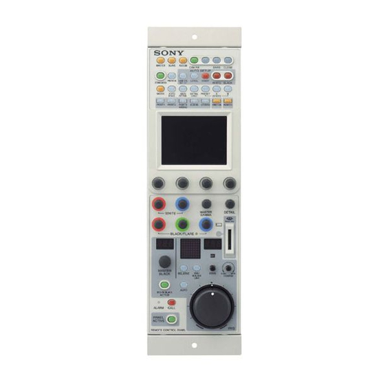
Sony RCP-D50 Service Manual
Remote control panel
Hide thumbs
Also See for RCP-D50:
- Operating instructions manual (62 pages) ,
- Operating instructions manual (194 pages)
Table of Contents
Advertisement
Quick Links
Advertisement
Table of Contents

Related Manuals for Sony RCP-D50


Summary of Contents for Sony RCP-D50
- Page 1 REMOTE CONTROL PANEL RCP-D50 RCP-D51 SERVICE MANUAL 1st Edition (Revised 2)
- Page 2 électrique, d’incendie ou de blessure n’effectuer que les réparations indiquées dans le mode d’emploi à moins d’être qualifié pour en effectuer d’autres. Pour toute réparation faire appel à une personne compétente uniquement. RCP-D50 RCP-D51...
- Page 3 Hävitä käytetty paristo valmistajan ohjeiden Remplacer uniquement avec une batterie du même mukaisesti. type ou d’un type équivalent recommandé par le constructeur. Mettre au rebut les batteries usagées conformément aux instructions du fabricant. 1 (P) RCP-D50 RCP-D51...
- Page 4 Gerät abschaltet und signalisiert “Batterie leer” oder nach längerer Gebrauchsdauer der Batterien “nicht mehr einwandfrei funktioniert”. Um sicherzugehen, kleben Sie die Batteriepole z.B. mit einem Klebestreifen ab oder geben Sie die Batterien einzeln in einen Plastikbeutel. 2 (P) RCP-D50 RCP-D51...
-
Page 5: Table Of Contents
Replacing the Touch Panel and Back Light .... 2-3 (E) 1-5. Location of Printed Wiring Boards ......1-3 (E) 2-3. Replacing the Master Black Control (RCP-D50) ..2-4 (E) 1-6. Circuit Description ........... 1-4 (E) 2-4. Removing/Reattaching the Joystick Assembly 1-6-1. - Page 6 7. Board Layouts MPU-126/126G .............. 7-2 VR-284 ................7-4 LED-405 ................. 7-5 LED-406 ................. 7-6 LED-407 ................. 7-7 CN-2425 ................. 7-8 CN-2426 ................. 7-8 VR-285 ................7-8 VR-286 ................7-8 VR-287 ................7-8 VR-288 ................7-8 2 (E) RCP-D50 RCP-D51...
-
Page 7: Manual Structure
Manual Structure Purpose of this manual This manual is the service manual for Remote Control Panel RCP-D50, RCP-D51. This manual is intended for use by the trained system enginneers and sevice engin- neers, and describes information (service overview, parts lists, schematic diagram and board layout) on the premise of component level service. -
Page 8: Contents
Section 5 Block Diagram Contains overall block diagram. Section 6 Schematic Diagrams Contains schematic diagrams for every circuit board and frame wiring. Section 7 Board Layouts Contains board layouts for every circuit board. 4 (E) RCP-D50 RCP-D51... -
Page 9: Service Overview
Color Video Camera DXC-D50 series. When using the file data stored in the memory stick, make (External View) sure that the file data for RCP-D50/D51 or DXC-D50 series is stored. No. Signal Specification PREVIEW S1 PREVIEW SW 1-2. -
Page 10: Removing The Bottom Assembly
CN6 on the CN-2426 board. Be careful not to bend the flexible card wire. This shortens the wire life. B3 x 8 B3 x 8 Flexible card wire CN-2426 board Bottom assembly * This figure is the RCP-D50. 1-2 (E) RCP-D50 RCP-D51... -
Page 11: Location Of Printed Wiring Boards
1-5. Location of Printed Wiring Boards RCP-D50 LED-405 board VR-284A board VR-287 board LED-407 board CN-2426 board MPU-126 board CN-2425 board VR-288 board VR-286 board RCP-D51 LED-405 board VR-284 board LED-406 board CN-2426 board MPU-126 board CN-2425 board VR-285 board... -
Page 12: Circuit Description
(IC4), is used as the operation clocks for the communication IC (IC305), memory stick interface (IC313), PLD (IC111), and the 8-bit sub microcomputer (IC1) on the LED-406/407 board. Other clock data are generated in the Clock Oscillator (X301) and the Clock IC (IC310). 1-4 (E) RCP-D50 RCP-D51... -
Page 13: Control System For Panel Operation And Display (Led-406/407 Boards)
1-6-2. Control System for Panel Operation and Display (LED-406/407 Boards) LED-406/407 Boards The LED-407 board and the LED-406 board is installed in the RCP-D50 and RCP-D51 respectively.They differ in the shape of the panel and the operation knobs. However, the functions of both circuits are the same: operation and display on the panel and their controls. -
Page 14: Functions Of Internal Switches
Connecting Install the flexible card wire as far as it will go, and push down the * marked portions of connector. Conductive S301 surface Flexible card wire (suffix -11) MPU-126 BOARD (A SIDE) 1-6 (E) RCP-D50 RCP-D51... -
Page 15: Forming The Flexible Card Wire
(C) to lock. 25 to 30 Unit : mm Conductive surface . Do not insert the flexible card wire on a slant. . Do not short the terminals of the flexible card wire. 1-7 (E) RCP-D50 RCP-D51... -
Page 16: Updating The Software
3. Press [Ver|Up] in the Diag Mode 2 menu. The display check the software version. will be switched to the Firmware Update display. Diag Mode 2 Main BL ON Sub BL OFF Ver Up Date Hours Moni. /Time Meter 1-8 (E) RCP-D50 RCP-D51... - Page 17 Update Update MASTER button SLAVE button 5. On completing updating, the message “COMPLET- ED” appears. FUNCTION button OTHERS button <FIRMWARE UPDATE 1/2> ERASING PROGRAMMING <FIRMWARE UPDATE 2/2> COMPLETED ERASING PROGRAMMING PANEL ACTIVE PANEL ACTIVE button 1-9 (E) RCP-D50 RCP-D51...
-
Page 18: Diagnosis
WHITE-B MASTER GAMMA DETAIL BLACK-R BLACK-G BLACK-B Master black control ring (RCP-D50) _90 to +75 (or more) MASTER BLACK control (RCP-D51) _90 to +90 _90 to +65 (or more) IRIS control lever (RCP-D50) IRIS control (RCP-D51) _90 to +99 IRIS SENS IRIS COAURSE *1: The rotary encoder 1 is the left most of the control knob. -
Page 19: Touch Panel Calibration
LCD first, and touch the center of x mark (Portion B) at the bottom right on the LCD using the stylus pen. The display will be switched to the Calibration Check display. Portion A Touch Panel Calibration PANEL ACTIVE PANEL ACTIVE button Portion B 1-11 (E) RCP-D50 RCP-D51... -
Page 20: And Fram
FRAM (IC8, IC9) on the MPU-126 board are 7. Perform the Touch Panel Calibration and Control replaced. Adjustment Value Calibration (RCP-D50). . Initializing the FRAM (Refer to the following proce- (Refer to Sections 1-11 and 1-13.) dures.) . -
Page 21: Control Adjustment Value Calibration (Rcp-D50)
6. Press [SAVE] on the left of the LCD to store the 1-13. Control Adjustment Value Calibration (RCP-D50) adjustment value. The default value is stored when the [SAVE] is 1-13-1. IRIS Control Adjustment Value Calibration pressed without moving the IRIS lever in step 5. -
Page 22: Master Black Control Adjustment Value Calibration
Mark Center Master black control ring 4. Press and light the [SET] at the bottom of the master black adjustment value indicator. The position of the master black control ring is set as the center position. 1-14 (E) RCP-D50 RCP-D51... -
Page 23: Optional Fixtures And Measuring Equipment
EX-932 Board A-8347-029-A For extension of MPU-126 board (Refer to Section 1-17.) L-shaped hexagonal wrench 7-700-736-04 For Torque Adjustment of Joystick (RCP-D50) (width across flat 2.5 mm) (Refer to Section 1-15.) PLD download fixture J-7120-140-A PLD data download cable (Refer to Section 1-16.) -
Page 24: Torque Adjustment Of Joystick (Rcp-D50)
1-15. Torque Adjustment of Joystick Adjustment for Disassembly (Coarse Adjustment) (RCP-D50) 1. Move the joystick lever fully in the arrow direction. When replacing a part in the joystick assembly of the RCP- 2. Adjust the hexagon socket head cap screw so that the joystick lever moves when the power of 250 ±... -
Page 25: Writing And Rewriting The Pld Internal Data
5. Upon completion of programming, check that error used. message is not displayed. Turn off the power of this . The PLD internal data is controlled in the Sony Database unit and back on. Server under the name Project file (E_xxx_xxx_xx_xx). -
Page 26: Extending The Mpu-126 Board
EX-932 board Be careful not to bend the flexible card wires. This shortens the wire life. VR-284/284A board MPU-126 board CN305 CN305 CN104 CN103 CN104 MPU-126 board CN103 EX-932 board VR-284/284A board Bottom assembly Bottom assembly 1-18 (E) RCP-D50 RCP-D51... -
Page 27: Description On Backup Battery
The lithium battery is a critical part to safe operation. current by steeply increasing the inner resistance when the Replace the component with Sony part whose part number device rises to a certain temperature due to overcurrent or is listed in the manual published by Sony. -
Page 28: Recommended Replacement Parts
1-21. Recommended Replacement Parts Parts listed below are recommended replacement parts. Replace them according to necessary. Fig No. Description Sony P/N Remarks Fig No. Description Sony P/N Remarks KNOB ASSY, X-3167-051-X rubber KEY (D/J), RUBBER 3-635-906-XX rubber VOLUME (RCP-D51) BLIND, RUBBER... -
Page 29: Notes On Repair Parts
Suffix of mount Suffix of mount board board 2. Standardization of Parts 1 -A Some repair parts supplied by Sony differ from those Available 2 -B used for the unit. These are because of parts common- Available ality and improvement. -
Page 31: Replacement Of Main Parts
Be careful not to bend the flexible card wire. This shortens conductor of the MPU-126 board. the wire life. Fig.1 1. Pull out the knobs (RCP-D50 : 11 pieces, RCP-D51 : Pliers PWB holder 12 pieces). Be careful not to lose the washers. - Page 32 CN2 on the VR-284A board to the connector CN1 on the LED-407 board. BTP2.6 x 6 VR-284A board BTP2.6 x 8 Shield plate (2) LCD unit Protection sheet LED-407 board 8. Reassemble the parts in the reverse order of removal. 2-2 (E) RCP-D50 RCP-D51...
-
Page 33: Replacing The Touch Panel And Backlight
The new touch panel is supplied with the protection sheet attached. Peel off the protection sheet before LCD unit board installation. Precision Precision P1.7 x 2.5 P1.7 x 2.5 Precision Claws B P1.7 x 2.5 Backlight Claws B Claws A Protection Touch panel sheet 2-3 (E) RCP-D50 RCP-D51... -
Page 34: Replacing The Master Black Control (Rcp-D50)
2-3. Replacing the Master Black Control 4. Remove the harness from the locking clamp as shown (RCP-D50) in the figure, and pull out the MB VR plate in the arrow direction. 1. Remove the two screws, and remove the cover tube. - Page 35 Grease (SGL-601) : 7-651-000-10 Applying value : About the tip of a cotton swab Applying area : Shaded area in the above figure. 13. Perform the Master Black Control Adjustment Value Calibration. (Refer to Section 1-13-2.) 2-5 (E) RCP-D50 RCP-D51...
-
Page 36: Removing/Reattaching The Joystick Assembly (Rcp-D50)
2-4. Removing/Reattaching the Joystick 4. Disconnect the harness from the connector CN2 on the Assembly (RCP-D50) LED-407 board and the flexible card wire from the connector CN1 on the VR-286 board. 1. Remove the master black control. (Refer to Section 2-3.) Be careful not to bend the flexible card wires. -
Page 37: Adjustment After Replacing The Iris Control (Rcp-D50)
2-5. Adjustment after Replacing the IRIS 6. Tighten the two setscrews in a position to gear the Control (RCP-D50) IRIS gear (A) with the drum. After replacing of the IRIS control of the joystick, adjust the IRIS gear (A) and the drum so that they mesh properly. -
Page 38: Replacing The Knob (D)/Iris Ring Assembly (Rcp-D51)
(D) in the arrow direction at 3.0 kgf.cm. Shaft of control Set screw Knob (D) Set screw 2.6 x 3 3 kgf.cm Knob (D) 2-8 (E) RCP-D50 RCP-D51... -
Page 39: Note On Tightening Screws
The screws shown in the following figures can replace for BTP2.6 x 8 from BTP2.6 x 6. Be sure to tighten the following screws (BTP2.6 x 6) of RCP-D50 this unit in vertical position with specified torque. BTP2.6 x 6 BTP2.6 screws: 32 x 10... -
Page 41: Spare Parts
Connector Block (RCP-D50/D51) Section 3 Spare Parts 3-1. Exploded Views B3 x 8 RCP-D51 RCP-D50 B2.6 x 5 B3 x 8 B2.6 x 5 Part No. SP Description A-8346-667-A s MOUNTED CIRCUIT BOARD, CN-2426 3-673-910-00 o SCREW (STEEL) 7-621-770-87 s SCREW +B2.6X5... - Page 42 Board Block (RCP-D50) BTP2.6 x 6 BTP2.6 x 6 B2.6 x 5 Part No. SP Description A-8346-665-A s MOUNTED CIRCUIT BOARD, VR-284A (Board No. suffix 11) A-8346-665-B s MOUNTED CIRCUIT BOARD, VR-284A (Board No. suffix 21 and higher) BTP2.6 x 6 A-8346-666-A s MOUNTED CIRCUIT BOARD, CN-2425 2.6 x 6...
- Page 43 Joystick and LCD Unit (RCP-D50) B2 x 3 BTP2.6 x 6 1: Exchange it for MPU-126 BOARD A-8346-679-A or B simultaneously. 2: Exchange it for MPU-126G BOARD A-1157-436-A simultaneously. B2.6 x 5 Precision P1.7 x 2.5 SET SCREW, HEXAGON Precision 2.6 x 3 (WP)
- Page 44 7-621-770-87 s SCREW +B2.6X5 7-685-533-14 s SCREW +BTP2.6X6 7-685-534-14 s SCREW +BTP2.6X8 1: Exchange it for LCD UNIT (RCP) 1-477-236-15 simultaneously. 2: Exchange it for LCD UNIT (RCP) 1-477-236-31 simultaneously. 3: Refer to Section 3-2. “FRAME of Electrical Parts List”. RCP-D50 RCP-D51...
- Page 45 (for LCD UNIT (RCP) suffix 31 and higher) 7-621-734-09 s SET-SCREW,HEX 2.6X3 (WP) 7-627-552-07 s SCREW, PRECISION +P1.7X2.5 1: Exchange it for MPU-126 BOARD A-8346-679-A or B simultaneously. 7-685-533-14 s SCREW +BTP2.6X6 2: Exchange it for MPU-126G BOARD A-1157-436-A simultaneously. RCP-D50 RCP-D51...
-
Page 46: Electrical Parts List
8-719-038-03 s LED CL-190Y-CD-T 8-719-061-16 s LED CL-190SR-C 8-719-038-03 s LED CL-190Y-CD-T 8-719-047-66 s LED CL-190D-CD 8-719-038-03 s LED CL-190Y-CD-T 8-719-991-00 s DIODE DAP222 8-719-061-16 s LED CL-190SR-C 8-719-991-00 s DIODE DAP222 8-719-038-03 s LED CL-190Y-CD-T 8-719-991-00 s DIODE DAP222 RCP-D50 RCP-D51... - Page 47 1-218-941-11 s RESISTOR,CHIP 100 1/16W (1005) 1-218-941-11 s RESISTOR,CHIP 100 1/16W (1005) 1-218-941-11 s RESISTOR,CHIP 100 1/16W (1005) 1-218-941-11 s RESISTOR,CHIP 100 1/16W (1005) 1-218-941-11 s RESISTOR,CHIP 100 1/16W (1005) 1-218-941-11 s RESISTOR,CHIP 100 1/16W (1005) 1-218-941-11 s RESISTOR,CHIP 100 1/16W (1005) RCP-D50 RCP-D51...
- Page 48 8-719-061-16 s LED CL-190SR-C 8-719-991-00 s DIODE DAP222 1-218-941-11 s RESISTOR,CHIP 100 1/16W (1005) 1-218-941-11 s RESISTOR,CHIP 100 1/16W (1005) 8-719-038-03 s LED CL-190Y-CD-T 1-218-941-11 s RESISTOR,CHIP 100 1/16W (1005) 8-719-991-00 s DIODE DAP222 1-218-941-11 s RESISTOR,CHIP 100 1/16W (1005) RCP-D50 RCP-D51...
- Page 49 8-759-082-58 s IC TC7W08FU IC10 8-759-271-86 s IC TC7SH04FU 1-414-398-11 s INDUCTOR (SMD) 10UH 1-414-404-11 s INDUCTOR (SMD) 100UH 1-414-398-11 s INDUCTOR (SMD) 10UH 8-719-939-53 s LED ARRAY LB-203ML 8-719-939-53 s LED ARRAY LB-203ML 8-719-050-78 s LED MD0708C-RG RCP-D50 RCP-D51...
- Page 50 8-729-929-08 s TRANSISTOR DTC123JE 1-218-939-11 s RESISTOR, CHIP 68 1/16W (1005) 8-729-929-08 s TRANSISTOR DTC123JE 1-218-939-11 s RESISTOR, CHIP 68 1/16W (1005) 8-729-928-54 s TRANSISTOR DTA123JE 1-208-707-11 s RESISTOR,CHIP 10K 1/16W (1005) 1-208-707-11 s RESISTOR,CHIP 10K 1/16W (1005) 3-10 RCP-D50 RCP-D51...
- Page 51 8-759-082-58 s IC TC7W08FU IC10 6-706-484-01 s IC TC7SH04FU(T5RSOYJF) 1-414-398-11 s INDUCTOR (SMD) 10UH 1-414-404-11 s INDUCTOR (SMD) 100UH 1-414-398-11 s INDUCTOR (SMD) 10UH 8-719-939-53 s LED ARRAY LB-203ML 8-719-939-53 s LED ARRAY LB-203ML 8-719-050-78 s LED MD0708C-RG 3-11 RCP-D50 RCP-D51...
- Page 52 8-729-929-08 s TRANSISTOR DTC123JE 1-218-939-11 s RESISTOR, CHIP 68 1/16W (1005) 8-729-929-08 s TRANSISTOR DTC123JE 1-218-939-11 s RESISTOR, CHIP 68 1/16W (1005) 8-729-928-55 s TRANSISTOR DTA123JE-TL 1-208-911-11 s RESISTOR, CHIP 10K (1005) 1-208-911-11 s RESISTOR, CHIP 10K (1005) 3-12 RCP-D50 RCP-D51...
- Page 53 ------------------------------------- (LED-406 BOARD [SUFFIX 21] for RCP-D51) LED-407 BOARD [SUFFIX 11] for RCP-D50 ------------------------------------- Ref. No. Ref. No. or Q'ty Part No. SP Description or Q'ty Part No. SP Description 1-208-911-11 s RESISTOR, CHIP 10K (1005) A-8346-673-A s MOUNTED CIRCUIT BOARD, LED-407...
- Page 54 (LED-407 BOARD [SUFFIX 11] for RCP-D50) (LED-407 BOARD [SUFFIX 11] for RCP-D50) Ref. No. Ref. No. or Q'ty Part No. SP Description or Q'ty Part No. SP Description 1-414-398-11 s INDUCTOR (SMD) 10UH 8-729-929-08 s TRANSISTOR DTC123JE 8-729-929-08 s TRANSISTOR DTC123JE...
- Page 55 ----------------------------------------- (LED-407 BOARD [SUFFIX 11] for RCP-D50) LED-407 BOARD [SUFFIX 21, 22-] for RCP-D50 ----------------------------------------- *1: [Board No. suffix 21] Ref. No. *2: [Board No. suffix 22-] or Q'ty Part No. SP Description 1-218-939-11 s RESISTOR, CHIP 68 1/16W (1005) Ref.
- Page 56 (LED-407 BOARD [SUFFIX 21, 22-] for RCP-D50) (LED-407 BOARD [SUFFIX 21, 22-] for RCP-D50) Ref. No. Ref. No. or Q'ty Part No. SP Description or Q'ty Part No. SP Description 1-414-398-11 s INDUCTOR (SMD) 10UH 8-729-929-08 s TRANSISTOR DTC123JE 1-414-404-11 s INDUCTOR (SMD) 100UH...
- Page 57 ------------------------- (LED-407 BOARD [SUFFIX 21, 22-] for RCP-D50) MPU-126 BOARD [SUFFIX 11] ------------------------- Ref. No. Ref. No. or Q'ty Part No. SP Description or Q'ty Part No. SP Description 1-218-939-11 s RESISTOR, CHIP 68 1/16W (1005) A-8346-679-A s MOUNTED CIRCUIT BOARD, MPU-126...
- Page 58 1-126-396-11 s CAPACITOR,ELECT 47MF/16V(CHIP) C412 1-164-943-11 s CAPACITOR,CHIP CERAMIC 0.01MF C490 1-126-396-11 s CAPACITOR,ELECT 47MF/16V(CHIP) C413 1-164-943-11 s CAPACITOR,CHIP CERAMIC 0.01MF C493 1-137-980-91 s CAPACITOR,CHIP CERAMIC 0.47MF C414 1-164-943-11 s CAPACITOR,CHIP CERAMIC 0.01MF C494 1-115-670-11 s CAPACITOR ELECT 220MF/35V(CHIP 3-18 RCP-D50 RCP-D51...
- Page 59 8-759-712-68 s IC EP1K50QC208-3 Q409 8-729-143-07 s TRANSISTOR 2SA1610-Y33 IC112 6-700-655-01 s IC LT1963ES8#TR Q410 8-729-143-07 s TRANSISTOR 2SA1610-Y33 IC114 8-759-662-38 s IC 74VHCT08AMTCX Q411 8-729-143-13 s TRANSISTOR 2SC4176-B34 IC115 6-702-749-01 s IC S-80928CNNB-G8YT2G Q412 8-729-143-13 s TRANSISTOR 2SC4176-B34 3-19 RCP-D50 RCP-D51...
- Page 60 1-208-683-11 s RESISTOR CHIP 1K 1/16W (1005) R129 1-208-635-11 s RESISTOR CHIP 10 1/16W (1005) R212 1-208-635-11 s RESISTOR CHIP 10 1/16W (1005) R130 1-208-683-11 s RESISTOR CHIP 1K 1/16W (1005) R213 1-218-990-11 s RESISTOR,CHIP 0 1/16W (1005) 3-20 RCP-D50 RCP-D51...
- Page 61 1-208-711-11 s RESISTOR CHIP 15K 1/16W (1005) R388 1-208-695-11 s RESISTOR CHIP 3.3K 1/16W(1005) R451 1-208-711-11 s RESISTOR CHIP 15K 1/16W (1005) R389 1-208-707-11 s RESISTOR,CHIP 10K 1/16W (1005) R452 1-208-711-11 s RESISTOR CHIP 15K 1/16W (1005) 3-21 RCP-D50 RCP-D51...
- Page 62 1-234-381-21 s RES, NETWORK 100KX4 (1005) R515 1-208-955-11 s RESISTOR CHIP 680K 1-234-381-21 s RES, NETWORK 100KX4 (1005) R516 1-218-941-11 s RESISTOR,CHIP 100 1/16W (1005) RB10 1-234-381-21 s RES, NETWORK 100KX4 (1005) R517 1-218-941-11 s RESISTOR,CHIP 100 1/16W (1005) 3-22 RCP-D50 RCP-D51...
- Page 63 (1005) RB309 1-234-381-21 s RES, NETWORK 100KX4 (1005) RB310 1-234-381-21 s RES, NETWORK 100KX4 (1005) RB311 1-234-381-21 s RES, NETWORK 100KX4 (1005) RB312 1-234-381-21 s RES, NETWORK 100KX4 (1005) RY301 1-755-380-21 s RELAY RY401 1-755-380-21 s RELAY 3-23 RCP-D50 RCP-D51...
- Page 64 1-125-777-81 s CAP, CHIP CERAMIC 0.1MF B 1005 C420 1-164-943-81 s CAP,CHIP CERAMIC 10000PF B1005 C146 1-125-777-81 s CAP, CHIP CERAMIC 0.1MF B 1005 C421 1-164-943-81 s CAP,CHIP CERAMIC 10000PF B1005 C422 1-164-842-81 s CAP,CHIP CERAMIC 2.0PF CK 1005 3-24 RCP-D50 RCP-D51...
- Page 65 6-801-893-02 s IC 29DL161TE-RCP75X-BOOT C501 1-164-934-81 s CAP, CHIP CERAMIC 330PF B 1005 8-759-524-10 s IC TC74VHC157FT(EL) C502 1-164-858-81 s CAP, CHIP CERAMIC 22PF CH 1005 C700 1-107-420-21 s CAP, CHIP ELECT 47MF 6-707-242-01 s IC R1LV0416CSB-5SI 3-25 RCP-D50 RCP-D51...
- Page 66 1-416-344-21 s COIL, CHOKE 10UH R107 1-220-870-81 s RES, CHIP 10 (1005) L701 1-416-948-21 s COIL, CHOKE 10UH R108 1-208-891-81 s RES, CHIP 1.5K (1005) L702 1-416-344-21 s COIL, CHOKE 10UH R109 1-208-863-81 s RES, CHIP 100 (1005) 3-26 RCP-D50 RCP-D51...
- Page 67 1-208-887-81 s RES, CHIP 1.0K (1005) R377 1-208-911-81 s RES, CHIP 10K (1005) R191 1-208-887-81 s RES, CHIP 1.0K (1005) R378 1-208-911-81 s RES, CHIP 10K (1005) R192 1-208-863-81 s RES, CHIP 100 (1005) R379 1-208-919-81 s RES, CHIP 22K (1005) 3-27 RCP-D50 RCP-D51...
- Page 68 1-208-927-81 s RES, CHIP 47K (1005) R501 1-208-887-81 s RES, CHIP 1.0K (1005) R441 1-220-870-81 s RES, CHIP 10 (1005) R502 1-208-887-81 s RES, CHIP 1.0K (1005) R442 1-208-911-81 s RES, CHIP 10K (1005) R503 1-208-947-81 s RES, CHIP 330K (1005) 3-28 RCP-D50 RCP-D51...
- Page 69 1-234-372-21 s RES, NETWORK 100 (1005X4) R577 1-208-863-81 s RES, CHIP 100 (1005) R578 1-220-870-81 s RES, CHIP 10 (1005) RB109 1-234-372-21 s RES, NETWORK 100 (1005X4) R700 1-218-990-81 s CONDUCTOR, CHIP (1005) RB110 1-234-372-21 s RES, NETWORK 100 (1005X4) 3-29 RCP-D50 RCP-D51...
- Page 70 1-125-777-81 s CAP, CHIP CERAMIC 0.1MF B 1005 C143 1-125-777-81 s CAP, CHIP CERAMIC 0.1MF B 1005 C144 1-125-777-81 s CAP, CHIP CERAMIC 0.1MF B 1005 C145 1-125-777-81 s CAP, CHIP CERAMIC 0.1MF B 1005 C146 1-125-777-81 s CAP, CHIP CERAMIC 0.1MF B 1005 3-30 RCP-D50 RCP-D51...
- Page 71 1-125-777-81 s CAP, CHIP CERAMIC 0.1MF B 1005 C411 1-164-943-81 s CAP,CHIP CERAMIC 10000PF B1005 C486 1-126-396-21 s CAP, CHIP ELECT 47MF (6.3X5.7) C412 1-164-943-81 s CAP,CHIP CERAMIC 10000PF B1005 C490 1-126-396-21 s CAP, CHIP ELECT 47MF (6.3X5.7) 3-31 RCP-D50 RCP-D51...
- Page 72 1-414-864-21 s FERRITE, EMI (SMD) (1608) L106 1-411-227-21 s COIL, CHOKE 100UH FB705 1-414-864-21 s FERRITE, EMI (SMD) (1608) L109 1-414-400-41 s INDUCTOR (SMD) 22.0UH FB706 1-414-864-21 s FERRITE, EMI (SMD) (1608) L302 1-414-398-41 s INDUCTOR (SMD) 10.0UH 3-32 RCP-D50 RCP-D51...
- Page 73 1-208-899-81 s RES, CHIP 3.3K (1005) R172 1-208-895-81 s RES, CHIP 2.2K (1005) 1-208-863-81 s RES, CHIP 100 (1005) R173 1-220-870-81 s RES, CHIP 10 (1005) 1-220-870-81 s RES, CHIP 10 (1005) R174 1-220-870-81 s RES, CHIP 10 (1005) 3-33 RCP-D50 RCP-D51...
- Page 74 1-208-911-81 s RES, CHIP 10K (1005) R418 1-208-867-81 s RES, CHIP 150 (1005) R348 1-208-911-81 s RES, CHIP 10K (1005) R419 1-208-887-81 s RES, CHIP 1.0K (1005) R349 1-208-911-81 s RES, CHIP 10K (1005) R420 1-208-871-81 s RES, CHIP 220 (1005) 3-34 RCP-D50 RCP-D51...
- Page 75 1-208-863-81 s RES, CHIP 100 (1005) R554 1-208-887-81 s RES, CHIP 1.0K (1005) R479 1-208-887-81 s RES, CHIP 1.0K (1005) R555 1-208-911-81 s RES, CHIP 10K (1005) R480 1-208-883-81 s RES, CHIP 680 (1005) R556 1-208-915-81 s RES, CHIP 15K (1005) 3-35 RCP-D50 RCP-D51...
- Page 76 1-234-381-21 s RES, NETWORK 100K (1005X4) X301 1-781-696-21 s VIBRATOR, CRYSTAL (32.768 KHz) RB25 1-234-381-21 s RES, NETWORK 100K (1005X4) X401 1-567-859-21 s VIBRATOR, CRYSTAL (3.579545 MHz) X402 1-567-860-11 s VIBRATOR, CRYSTAL (4.433619 MHz) RB26 1-234-381-21 s RES, NETWORK 100K (1005X4) 3-36 RCP-D50 RCP-D51...
- Page 77 ----------------------------- VR-284/284A BOARD [SUFFIX 11] (VR-284/284A BOARD [SUFFIX 11]) ----------------------------- *a: [VR-284 for RCP-D51] Ref. No. *b: [VR-284A for RCP-D50] or Q'ty Part No. SP Description Ref. No. 1-770-297-21 o HOUSING, CONNECTOR 12P or Q'ty Part No. SP Description 1-785-207-11 s HOUSING, CONNECTOR 25P...
- Page 78 (VR-284/284A BOARD [SUFFIX 11]) VR-284/284A BOARD [SUFFIX 21, 22, 23, 24-] ------------------------------------------ *a: [VR-284 for RCP-D51] Ref. No. *b: [VR-284A for RCP-D50] or Q'ty Part No. SP Description *1: [Board No. suffix 21, 22] 1-208-691-11 s RESISTOR CHIP 2.2K 1/16W(1005) *2: [Board No.
- Page 79 1-414-864-11 s INDUCTOR, MICRO (CHIP TYPE) FB512 1-414-864-11 s INDUCTOR, MICRO (CHIP TYPE) R522 1-219-610-11 s RESISTOR, (SQUARE TYPE) 0.022 FB513 1-414-864-11 s INDUCTOR, MICRO (CHIP TYPE) R523 1-208-683-11 s RESISTOR CHIP 1K 1/16W (1005) FB514 1-414-864-11 s INDUCTOR, MICRO (CHIP TYPE) 3-39 RCP-D50 RCP-D51...
- Page 80 ------------------------ (VR-284/284A BOARD [SUFFIX 21, 22, 23, 24-]) VR-287 BOARD for RCP-D50 ------------------------ Ref. No. Ref. No. or Q'ty Part No. SP Description or Q'ty Part No. SP Description 1-234-378-11 s RES, NETWORK 10KX4 (1005) A-8346-671-A s MOUTNED C.BOARD,VR-287 1-234-378-11 s RES, NETWORK 10KX4 (1005)
-
Page 81: Supplied Accessories
*S 1-574-144-12 s WIRE, FLAT TYPE (12 CORE) (From CN3/LED-407 (suffix 11, 21) to CN1/VR-286) HN009 ------------ HARNESS, SUB (DIAL) (To CN2/LED-406) 1-569-196-11 o HOUSING, CONNECTOR 3P 3pcs 1-569-194-11 o TERMINAL, SOLDERLESS (To W1/VR-285) 1-562-736-11 o HOUSING,CONNECTOR 3P 3-41 RCP-D50 RCP-D51... - Page 83 In addition, for semiconductors with ID Nos., refer to the separate CD-ROM titled “Semiconductor Pin Assignments” (Sony Part No. 9-968-546-06) that allows searching for parts by semiconductor type or ID No. The semiconductors in the manual or on the CD-ROM are listed by equivalent types.
- Page 84 TC7SH04FU ..............TC7S04F TC7SH04FU-TE85R ............TC7S04F TC7W04FU ..............TC7W04F TC7W04FU(TE12R) ............TC7W04F TC7W08FU ..............TC7W08F TC7W08FU(TE12R) ............TC7W08F TC7W66FU(TE12R) ............TC4W66F TC7WH04FU(TE12R) ............TC7W04F TC7WH08FU(TE12R) ............TC7W08F TC7WH74FU(TE12R) ........... TC7W74FU TLC7733IPWR-12 ............ TLC7733IPWR UPD4991AGS ............UPD4991AGS UPD4991AGS-E2 ............. UPD4991AGS RCP-D50 RCP-D51...
-
Page 85: Block Diagram
Index Index Section 5 Block Diagram Index Page Overall ............... 5-2 RCP-D50 RCP-D51... - Page 86 Overall Overall RCP-D50 RCP-D51...
-
Page 87: Overall
Overall Overall Overall RCP-D50 RCP-D51... - Page 89 C. CN-2425 ............. 6-19 CN-2426 ............. 6-19 L. LED-405 ............. 6-12 LED-406 ............. 6-14 LED-407 ............. 6-16 M. MPU-126/126G ..........6-2 V. VR-284/284A ............. 6-10 VR-285 ............... 6-19 VR-286 ............... 6-19 VR-287 ............... 6-18 VR-288 ............... 6-18 Frame Wiring ............. 6-19 RCP-D50 RCP-D51...
- Page 90 IC21 (4/4) 100k TC7W04FU(TE12R) +3.3V RB13 100k 0.1uF IC21 (2/4) TC7W04FU(TE12R) RY/BY RB14 100k COM_INT RB15 100k MS_CTRL_INT +3.3V TLC7733IPWR-12 RESET CONTROL RESET RESET RESIN RESET SENSE RESET CONTROL BUS 0.1uF 10uF ADDRESS BUS DATA BUS CHIP SELECT RCP-D50 RCP-D51...
- Page 91 5V_D1 5V_D0 FRAM RB42 VSS1 VSS2 +3.3V IC18 (1/2) 0.1uF NC7SZ04P5X HM62V16256CLTT-5SLZ +3.3V 0.1uF IC17 (3/3) TC7WH08FU(TE12R) IC18 (2/2) NC7SZ04P5X I/O BUS I/O_BUS 002,003,004 CONTROL_BUS 002,003 ADDRESS_BUS 002,003 DATA_BUS 002,003 CHIP_SELECT 002,003 MPU-126 (1/4) BOARD NO. 1-688-945-11 CAX-089A_MPU-126_008_1 RCP-D50 RCP-D51...
- Page 92 R120 C113 C114 C128 C129 CN101 1.5k 0.1uF 82uF 0.1uF 82uF 6.3V 6.3V R164 R121 TRST TRST TRST C136 R187 R122 2.2k 2.2k E101 0.1uF (MODE) IC107 (3/3) TC7WH08FU(TE12R) +3.3V IC107 (2/3) TC7WH08FU(TE12R) C131 0.1uF IC108 74VHC244MTCX R129 RCP-D50 RCP-D51...
- Page 93 001,002,003,004 LCD_UNREG ADDRESS_BUS 001,003 LCD_UNREG DATA_BUS 001,003 RB103 RB104 RB105 RB107 RB109 RB111 RB112 CONTROL_BUS 001,002,003 CHIP_SELECT 001,003 FRAME_GND FRAME_GND +3.3V R180 R181 100k 100k CN105 F-GND R182 +3.3V OPTION_RE(B) OPTION_RE(A) R183 MPU-126 (2/4) BOARD NO. 1-688-945-11 CAX-089A_MPU-126_008_2 RCP-D50 RCP-D51...
- Page 94 DIPSW7 IC303 (7/7) 74VHC04MTCX DIPSW5 DIPSW3 DIPSW4 RB306 DIPSW2 100k DIPSW3 DIPSW1 DIPSW2 C313 C314 DIPSW0 0.1uF 0.1uF DIPSW1 DIPSW0 R323 R325 IC303 (3/7) IC304 (1/3) 74VHC04MTCX TC7WH08FU(TE12R) COM_INT IC304 (2/3) IC303 (4/7) TC7WH08FU(TE12R) 74VHC04MTCX IC303 (6/7) 74VHC04MTCX RCP-D50 RCP-D51...
- Page 95 (3/5) 74VHCT08AMTCX COM1_CONNECT COM1_CONNECT R355 COM0_CONNECT COM0_CONNECT AUX_6 AUX6 BUZZER5 R356 IC312 (4/5) RB312 74VHCT08AMTCX IC314 (2/2) 100k AUX_7 R374 AUX7 NJM2904V(TE2) R383 R357 BUZZER_OUT IC303 (5/7) 74VHC04MTCX D304 Q305 MPU-126 (3/4) DAP222-TL DTC123JE-TL BOARD NO. 1-688-945-11 CAX-089A_MPU-126_008_3 RCP-D50 RCP-D51...
- Page 96 R445 C421 R448 C426 R451 C427 R459 C428 R462 C431 R465 C433 R467 C435 0.01uF 0.01uF 0.01uF 0.01uF 0.01uF 0.01uF 0.01uF 0.01uF 4.7k 0.01uF 0.01uF 0.01uF R560 COLOR CONTRAST SHARPNESS V_COM_AMP SUB_BRT_R SUB_BRT_B BRIGHT RGB_GAIN GAMMA_0 GAMMA_2 (ANALOG) RCP-D50 RCP-D51...
- Page 97 C440 0.01uF +5V_A (ANALOG) SL401 IC402 (3/5) 74VHCT08AMTCX C477 0.01uF (ANALOG) (ANALOG) SL402 R528 DA_B X-COM LCD_B R529 DA_G Y-COM LCD_G (ANALOG) R530 DA_R Z-COM LCD_R IC406 74VHC4053MTCX C478 0.01uF (ANALOG) (ANALOG) MPU-126 (4/4) BOARD NO. 1-688-945-11 CAX-089A_MPU-126_008_4 RCP-D50 RCP-D51...
- Page 98 +3.3V RB13 100k 0.1uF IC21 (2/4) RY/BY TC7W04FU(TE12R) RB14 100k COM_INT RB15 100k MS_CTRL_INT +3.3V TLC7733IPWR-12 RESET CONTROL RESET RESET RESIN RESET SENSE RESET CONTROL BUS 0.1uF 10uF ADDRESS BUS DATA BUS CHIP SELECT 6-2 (a) 6-2 (a) RCP-D50 RCP-D51...
- Page 99 74LCX245MTCX R1LV0416CSB-5SI +3.3V 0.1uF IC17 (3/3) TC7WH08FU(TE12R) IC18 (2/2) NC7SZ04P5X I/O BUS I/O_BUS 002,003,004 CONTROL_BUS 002,003 ADDRESS_BUS 002,003 DATA_BUS 002,003 CHIP_SELECT 002,003 MPU-126 (1/4) BOARD NO. 1-688-945-21, 22 MPU-126G (1/4) BOARD NO. 1-688-945-22 RCP-D50_MPU-126_003_1 6-3 (a) 6-3 (a) RCP-D50 RCP-D51...
- Page 100 TC7WH08FU(TE12R) R190 R191 R115 R119 C131 2.2k 2.2k 0.1uF IC108 SHDN SHDN 74VHC244MTCX R163 R120 C114 C128 C129 1.5k C113 0.1uF 0.1uF 82uF 82uF 6.3V 6.3V R129 R164 R121 R187 R122 2.2k 2.2k E101 6-4 (a) 6-4 (a) RCP-D50 RCP-D51...
- Page 101 RB107 RB109 RB111 RB112 CONTROL_BUS 001,002,003 CHIP_SELECT 001,003 FRAME_GND FRAME_GND +3.3V R180 R181 100k 100k CN105 R182 F-GND +3.3V MPU-126 (2/4) OPTION_RE(B) OPTION_RE(A) R183 BOARD NO. 1-688-945-21, 22 MPU-126G (2/4) BOARD NO. 1-688-945-22 RCP-D50_MPU-126_003_2 6-5 (a) 6-5 (a) RCP-D50 RCP-D51...
- Page 102 74VHC04MTCX DIPSW3 DIPSW4 RB306 DIPSW2 100k DIPSW3 DIPSW1 DIPSW2 C313 C314 DIPSW0 0.1uF 0.1uF DIPSW1 DIPSW0 R323 R325 IC303 (3/7) IC304 (1/3) 74VHC04MTCX TC7WH08FU(TE12R) COM_INT IC304 (2/3) IC303 (4/7) TC7WH08FU(TE12R) 74VHC04MTCX IC303 (6/7) 74VHC04MTCX 6-6 (a) 6-6 (a) RCP-D50 RCP-D51...
- Page 103 RB312 74VHCT08AMTCX IC314 (2/2) 100k AUX_7 R374 AUX7 NJM2904V(TE2) R357 R383 IC312 (5/5) BUZZER_OUT 74VHCT08AMTCX IC303 (5/7) 74VHC04MTCX MPU-126 (3/4) D304 Q305 DAP222-TL DTC123JE-TL BOARD NO. 1-688-945-21, 22 MPU-126G (3/4) BOARD NO. 1-688-945-22 RCP-D50_MPU-126_003_3 6-7 (a) 6-7 (a) RCP-D50 RCP-D51...
- Page 104 R451 C427 R459 C428 R462 C431 R465 C433 R467 C435 0.01uF 0.01uF 0.01uF 0.01uF 0.01uF 0.01uF 0.01uF 0.01uF 4.7k 0.01uF 0.01uF 0.01uF R560 COLOR CONTRAST SHARPNESS V_COM_AMP SUB_BRT_R SUB_BRT_B BRIGHT RGB_GAIN GAMMA_0 GAMMA_2 (ANALOG) 6-8 (a) 6-8 (a) RCP-D50 RCP-D51...
- Page 105 (ANALOG) (ANALOG) SL402 R528 DA_B X-COM LCD_B R529 DA_G Y-COM LCD_G (ANALOG) R530 DA_R Z-COM LCD_R IC406 74VHC4053MTCX C478 0.01uF (ANALOG) (ANALOG) MPU-126 (4/4) BOARD NO. 1-688-945-21, 22 MPU-126G (4/4) BOARD NO. 1-688-945-22 RCP-D50_MPU-126_003_4 6-9 (a) 6-9 (a) RCP-D50 RCP-D51...
- Page 106 +3.3V RB13 100k 0.1uF IC21 (2/4) RY/BY TC7W04FU(TE12R) RB14 100k COM_INT RB15 100k MS_CTRL_INT +3.3V TLC7733IPWR-12 CONTROL RESET PIO_RESET RESET RESIN RESET SENSE RESET CONTROL BUS 0.1uF 10uF ADDRESS BUS DATA BUS CHIP SELECT 6-2 (b) 6-2 (b) RCP-D50 RCP-D51...
- Page 107 VSS1 VSS2 +3.3V IC18 (1/2) 0.1uF NC7SZ04P5X R1LV0416CSB-5SI +3.3V 0.1uF IC17 (3/3) TC7WH08FU(TE12R) IC18 (2/2) NC7SZ04P5X I/O BUS I/O_BUS 002,003,004 CONTROL_BUS 002,003 ADDRESS_BUS 002,003 DATA_BUS 002,003 CHIP_SELECT 002,003 MPU-126/126G (1/4) BOARD NO. 1-688-945-31 RCP-D50_MPU-126G_002_1 6-3 (b) 6-3 (b) RCP-D50 RCP-D51...
- Page 108 R115 R119 C131 2.2k 2.2k 0.1uF R112 IC108 SHDN SHDN 74VHC244MTCX R163 R120 C114 C128 C129 1.5k C113 0.1uF 0.1uF 82uF 82uF 6.3V 6.3V R129 R164 R121 R111 TDO_L R187 R122 2.2k 2.2k E101 6-4 (b) 6-4 (b) RCP-D50 RCP-D51...
- Page 109 DATA_BUS 001,003 RB103 RB104 RB105 RB107 RB109 RB111 RB112 CONTROL_BUS 001,002,003 CHIP_SELECT 001,003 FRAME_GND FRAME_GND +3.3V R180 R181 100k 100k CN105 NM F-GND R182 +3.3V MPU-126/126G (2/4) OPTION_RE(B) OPTION_RE(A) R183 BOARD NO. 1-688-945-31 RCP-D50_MPU-126G_002_2 6-5 (b) 6-5 (b) RCP-D50 RCP-D51...
- Page 110 DIPSW6 +3.3V DIPSW7 IC303 (7/7) 74VHC04MTCX DIPSW3 DIPSW2 RB306 100k DIPSW1 C313 C314 DIPSW0 0.1uF 0.1uF R323 R325 IC303 (3/7) IC304 (1/3) 74VHC04MTCX TC7WH08FU(TE12R) COM_INT IC304 (2/3) IC303 (4/7) TC7WH08FU(TE12R) 74VHC04MTCX IC303 (6/7) 74VHC04MTCX 6-6 (b) 6-6 (b) RCP-D50 RCP-D51...
- Page 111 0.1uF AUX6 BUZZER5 R356 IC312 (4/5) RB312 74VHCT08AMTCX 100k AUX_7 R374 IC314 (2/3) AUX7 NJM2904V(TE2) R383 R357 IC312 (5/5) BUZZER_OUT 74VHCT08AMTCX IC303 (5/7) 74VHC04MTCX D304 Q305 DAP222-TL DTC123JE-TL MPU-126/126G (3/4) BOARD NO. 1-688-945-31 RCP-D50_MPU-126G_002_3 6-7 (b) 6-7 (b) RCP-D50 RCP-D51...
- Page 112 R451 C427 R459 C428 R462 C431 R465 C433 R467 C435 0.01uF 0.01uF 0.01uF 0.01uF 0.01uF 0.01uF 0.01uF 0.01uF 4.7k 0.01uF 0.01uF 0.01uF R560 COLOR CONTRAST SHARPNESS V_COM_AMP SUB_BRT_R SUB_BRT_B BRIGHT RGB_GAIN GAMMA_0 GAMMA_2 (ANALOG) 6-8 (b) 6-8 (b) RCP-D50 RCP-D51...
- Page 113 SL401 IC402 (3/5) 74VHCT08AMTCX C477 0.01uF (ANALOG) (ANALOG) SL402 R528 DA_B X-COM LCD_B R529 DA_G Y-COM LCD_G (ANALOG) R530 DA_R Z-COM LCD_R IC406 74VHC4053MTCX MPU-126/126G (4/4) C478 0.01uF (ANALOG) BOARD NO. 1-688-945-31 (ANALOG) RCP-D50_MPU-126G_002_4 6-9 (b) 6-9 (b) RCP-D50 RCP-D51...
- Page 114 +LCD_REG 4.7uF RXD_MPU SHDN 100uF TXD_MPU 100uF RESET RESET RB060L-40TE25 100uF 100uF 4.7k BUZZER+ 0.1uF BUZZER- 4.7uF 1.5k 0.1uF +3.3V +3.3V-1 +3.3V 10uH +3.3V +3.3V +3.3V 47uF +12V +12V +12V LCD_UNREG +LCD_REG LCD_UNREG FRAME_GND FRAME_GND F-GND 6-10 6-10 RCP-D50 RCP-D51...
- Page 115 (3/7) 0.022uF 74VHC04MTCX Frame_GND RB13 (4/7) DETAIL 0.022uF 74VHC04MTCX 0.1uF 0.1uF 0.1uF 0.1uF 62 61 FRAME GND 0.022uF F-GND 0.022uF F-GND F-GND VR-284 VR-284A EN12 VR-284/284A BOARD NO. 1-688-935-11 VR-284 : RCP-D51 VR-284A : RCP-D50 CAX-089A_VR-284_005_1 6-11 6-11 RCP-D50 RCP-D51...
- Page 116 INTVCC 33pF C507 0.001uF SGND PGND 3.3VOUT ITH2 BOOST2 +3.3V +3.3V-1 VOSENSE2 +3.3V 10uH SENSE2- +3.3V SENSE2+ RUN/SS2 +3.3V C520 +3.3V 2.2uF 47uF C519 4.7uF +12V +12V +12V LCD_UNREG +LCD_REG LCD_UNREG FRAME_GND FRAME_GND F-GND 6-10 (a) 6-10 (a) RCP-D50 RCP-D51...
- Page 117 RB13 74VHC04MTCX Frame_GND DETAIL 0.022uF (4/7) 0.1uF 0.1uF 0.1uF 0.1uF 62 61 74VHC04MTCX FRAME GND 0.022uF F-GND 0.022uF F-GND F-GND VR-284/284A BOARD NO. 1-688-935-21, 22, 23, 24 VR-284 : RCP-D51 VR-284A : RCP-D50 RCP-D50_VR-284A_003_1 6-11 (a) 6-11 (a) RCP-D50 RCP-D51...
- Page 118 SWL3 SWL3 SDIN0 SDIN0 SDIN1 SDIN1 SDIN2 0.1uF SDIN2 SDIN3 SDIN3 SDIN4 SDIN4 SDIN5 SDIN5 SDIN6 SDIN6 10uH +5V-1 +5V(LED) 10uH +5V(LED) +5V(LED) TC74VHC238FT(EL) 0.1uF 0.1uF SWL0 SWAD0 SWL1 SWAD1 SWL2 SWAD2 SWL3 SWAD3 GND-1 0.1uF 6-12 6-12 RCP-D50 RCP-D51...
- Page 119 CL-190D-CD-T CL-190D-CD-T CL-190Y-CD-T CL-190Y-CD-T GND-1 LEDOUT1 LEDOUT2 CL12 CL16 CL20 CL24 CL28 CL32 CL36 CL40 CL44 CL48 CL52 CL56 LEDOUT3 LEDOUT4 DAP222-TL DAP222-TL DAP222-TL DAP222-TL LEDOUT5 LEDOUT6 RB10 SWAD3 LPAD3 GND-1 LED-405 BOARD NO. 1-688-942-11 CAX-089A_LED-405_005_1 6-13 6-13 RCP-D50 RCP-D51...
- Page 120 SDIN0 SDIN0 SDIN1 SDIN1 SDIN2 0.1uF SDIN2 SDIN3 SDIN3 SDIN4 SDIN4 SDIN5 SDIN5 SDIN6 SDIN6 10uH +5V-1 +5V(LED) 10uH +5V(LED) +5V(LED) TC74VHC238FT(EL) 0.1uF 0.1uF SWL0 SWAD0 SWL1 SWAD1 SWL2 SWAD2 SWL3 SWAD3 GND-1 0.1uF 6-12 (a) 6-12 (a) RCP-D50 RCP-D51...
- Page 121 CL-190Y-CD-T CL-190Y-CD-T GND-1 LEDOUT1 LEDOUT2 CL12 CL16 CL20 CL24 CL28 CL32 CL36 CL40 CL44 CL48 CL52 CL56 LEDOUT3 LEDOUT4 DAP222-TL DAP222-TL DAP222-TL DAP222-TL LEDOUT5 LEDOUT6 RB10 SWAD3 LPAD3 GND-1 LED-405 BOARD NO. 1-688-942-21 RCP-D50_LED-405_002_1 6-13 (a) 6-13 (a) RCP-D50 RCP-D51...
- Page 122 0.01uF +3.3V +3.3V 100uH 82uF 0.01uF 6.3V FRAME GND FRAME GND RB10 RB15 RB16 RB11 RB13 RB14 100k RB12 100k 100k 100k 100k 100k 100k 100k F-GND +5V-A COARSE SENS IRIS 100k F-GND 0.1uF 0.1uF 0.1uF 6-14 6-14 RCP-D50 RCP-D51...
- Page 123 PANEL ALARM FLARE TC74VHC238FT(EL) +3.3V 0.1uF 10uF RB19 RB21 LEDOUT0 SWL0 SML-020MLTT86 LEDOUT1 LD-101YY LD-101YY SML-020MLTT86 SWL1 LEDOUT2 SWL2 LEDOUT3 SWL3 LEDOUT4 SWAD4 LEDOUT5 LEDOUT6 LEDOUT7 LPAD5 0.1uF RB20 LED-406 BOARD NO. 1-688-943-11 FOR RCP-D51 CAX-089A_LED-406_005_1 6-15 6-15 RCP-D50 RCP-D51...
- Page 124 +3.3V 100uH 82uF 0.01uF 6.3V FRAME GND FRAME GND RB10 RB11 RB14 RB15 RB16 RB12 RB13 100k 100k 100k 100k 100k 100k 100k 100k F-GND +5V-A COARSE SENS IRIS 100k F-GND 0.1uF 0.1uF 0.1uF 6-14 (a) 6-14 (a) RCP-D50 RCP-D51...
- Page 125 FLARE TC74VHC238FT(EL) +3.3V 0.1uF 10uF RB19 RB21 LEDOUT0 MU11-4201 MU11-4201 SWL0 SML-020MLTT86 LEDOUT1 SML-020MLTT86 SWL1 LEDOUT2 SWL2 LEDOUT3 SWL3 LEDOUT4 SWAD4 LEDOUT5 LEDOUT6 LEDOUT7 LPAD5 LED-406 0.1uF RB20 BOARD NO. 1-688-943-21 FOR RCP-D51 RCP-D51_LED-406_003_1 6-15 (a) 6-15 (a) RCP-D50 RCP-D51...
- Page 126 RB10 RB12 RB13 RB15 RB16 100k 100k RB14 100k 100k 100k 100k 100k 100k F-GND PREVIEW_S2 PREVIEW_S1 +5V-A IRIS MASTER BLACK PREVIEW S1 100k 100k PREVIEW S2 0.1uF 0.1uF F-GND COARSE SENS 100k 100k 0.1uF 0.1uF 6-16 6-16 RCP-D50 RCP-D51...
- Page 127 PANEL ALARM FLARE TC74VHC238FT(EL) +3.3V 0.1uF 10uF RB19 RB21 LEDOUT0 SWL0 LEDOUT1 SML-020MLTT86 LD-101YY LD-101YY SML-020MLTT86 SWL1 LEDOUT2 SWL2 LEDOUT3 SWL3 LEDOUT4 SWAD4 LEDOUT5 LEDOUT6 LEDOUT7 LPAD5 0.1uF RB20 LED-407 BOARD NO. 1-688-944-11 FOR RCP-D50 CAX-089B_LED-407_005_1 6-17 6-17 RCP-D50 RCP-D51...
- Page 128 100k RB10 RB12 RB13 RB14 100k 100k 100k 100k 100k 100k 100k F-GND PREVIEW_S2 PREVIEW_S1 +5V-A IRIS MASTER BLACK PREVIEW S1 100k 100k PREVIEW S2 0.1uF 0.1uF F-GND COARSE SENS 100k 100k 0.1uF 0.1uF 6-16 (a) 6-16 (a) RCP-D50 RCP-D51...
- Page 129 +3.3V 0.1uF TC74VHC238FT(EL) 10uF RB19 LEDOUT0 MU11-4201 MU11-4201 LEDOUT1 SML-020MLTT86 RB21 SML-020MLTT86 LEDOUT2 SWL0 LEDOUT3 SWL1 LEDOUT4 SWL2 LEDOUT5 SWL3 LEDOUT6 SWAD4 LEDOUT7 LPAD5 LED-407 RB20 BOARD NO. 1-688-944-21, 22 0.1uF FOR RCP-D50 RCP-D50_LED-407_003_1 6-17 (a) 6-17 (a) RCP-D50 RCP-D51...
- Page 130 (Board in) (3/5) (2/5) IRIS (4/5) 0.1uF PREVIEW1 (5/5) PREVIEW2 PREVIEW1 RV1(1/2) PREVIEW2 0.1uF PREVIEW1 VR-287 PREVIEW2 BOARD NO. 1-688-938-11 RV1 (2/2) To VR-287 FOR RCP-D50 (Board in) CAX-089B_VR-287_005_1 F-GND VR-288 BOARD NO. 1-688-939-11 FOR RCP-D50 CAX-089B_VR-288_005_1 6-18 6-18 RCP-D50 RCP-D51...
- Page 131 (DIAL) T_RXD T_TXD IRIS IRIS RESET +3.3V IRIS CLK(NC) UNREG_GND 0.01uF 0.01uF UNREG MAIN_Bright MAIN_ON Dial VR DETECT SUB_Bright SUB_ON RCP-D50 UNIT LCD_B HN005 MPU-126/126G VR-284 HARNESS,SUB LCD_G (IRIS) VR-288 VR-287 (RCP-D51) LCD_R IRIS IRIS HN007 VR-284A LED-406 MASTER BLACK...
- Page 133 Page C. CN-2425 ............. 7-8 CN-2426 ............. 7-8 L. LED-405 ............. 7-5 LED-406 ............. 7-6 LED-407 ............. 7-7 M. MPU-126/126G ..........7-2 V. VR-284 ............... 7-4 VR-285 ............... 7-8 VR-286 ............... 7-8 VR-287 ............... 7-8 VR-288 ............... 7-8 RCP-D50 RCP-D51...
- Page 134 * C3 RB106 *C2 C307 C469 IC111 R164 R335 R432 R528 C308 C470 * D1 IC112 * C3 R165 * D1 R336 R433 R529 RB107 C309 C471 IC114 * D1 R166 * D1 R337 R434 R530 RB108 *C2 RCP-D50 RCP-D51...
- Page 135 R215 RV401 R404 R157 R216 R162 C440 C497 R134 R145 R217 R106 R564 R135 R138 R193 R195 C494 R136R137 R194 R213 R222 R104 FB105 FB104 R161 CN104 FB106 MPU-126 MPU-126 -A SIDE- -B SIDE- SUFFIX: -11 SUFFIX: -11 RCP-D50 RCP-D51...
- Page 136 * B2 C490 IC17 * B3 Q419 R164 R339 R436 R536 * D3 RB101 * C1 C323 * B2 C493 * E3 IC18 * A3 Q420 R165 R340 R437 R537 * D3 RB102 * C1 7-2 (a) 7-2 (a) RCP-D50 RCP-D51...
- Page 137 R554 R524 R503 R513 C471 C473 C432 R492 C455 C490 C438 Q416 C483 R490 R484 R578 R489 C405 RV401 R162 R106 R195 C494 CN104 MPU-126 MPU-126 -A SIDE- -B SIDE- SUFFIX: -21 SUFFIX: -21 7-3 (a) 7-3 (a) RCP-D50 RCP-D51...
- Page 138 C322 * B2 C490 IC17 * B3 Q419 R164 R339 R436 R536 * D3 RB42 C323 * B2 C493 * E3 IC18 * A3 Q420 R165 R340 R437 R537 * D3 RB101 * C1 7-2 (b) 7-2 (b) RCP-D50 RCP-D51...
- Page 139 R443 Q408 C432 R438 C499 R442 C490 C438 Q416 R522 C500 C483 R521 R407 C480 R215 R404 R216 R564 C494 R222 FB105 CN104 FB106 MPU-126 MPU-126 -A SIDE- -B SIDE- SUFFIX: -22 SUFFIX: -22 7-3 (b) 7-3 (b) RCP-D50 RCP-D51...
- Page 140 IC13 * A3 R166 * D1 R361 R456 R562 * E2 RB304 * B2 C323 * B2 C493 IC14 * B3 * B3 R167 * D1 R362 R457 R563 * E2 RB305 * B2 7-2 (c) 7-2 (c) RCP-D50 RCP-D51...
- Page 141 R552 R429 L401 R549 C412 R518 R428 R514 R424 R577 C402 Q419 Q401 C409 R158 C497 R157 R403 FB106 R215 R195 R535 R216 R196 MPU-126G MPU-126G -A SIDE- -B SIDE- SUFFIX: -31 SUFFIX: -31 7-3 (c) 7-3 (c) RCP-D50 RCP-D51...
- Page 142 * E3 * D3 * E1 * E3 * E2 RB10 * E1 RB11 RB12 RB13 * E2 * E2 * E2 * E2 *:B SIDE EN10 EN11 EN12 VR-284 VR-284 -A SIDE- -B SIDE- SUFFIX: -11 SUFFIX: -11 RCP-D50 RCP-D51...
- Page 143 * A1 CL51 * A1 CL52 CL53 CL54 * A2 CL55 * A2 CL56 CL10 CL11 CL12 CL13 CL14 CL15 CL16 CL17 CL18 CL19 CL20 CL21 CL22 CL23 CL24 CL25 CL26 CL27 CL28 CL29 CL30 CL31 CL32 CL33 CL34 RCP-D50 RCP-D51...
- Page 144 FB513 *E1 * E2 C533 C532 FB514 *E1 * E3 * E3 L500 * E3 L501 * E3 VR-284 VR-284 -A SIDE- -B SIDE- SUFFIX: -21, 22, 23, 24 SUFFIX: -21, 22, 23, 24 7-4 (a) 7-4 (a) RCP-D50 RCP-D51...
- Page 145 CL18 CL19 * B2 CL20 * B2 * B1 CL21 * B1 CL22 CL23 * B2 CL24 * B2 * B1 CL25 CL26 * B1 CL27 * B2 * B2 CL28 * B1 CL29 7-5 (a) 7-5 (a) RCP-D50 RCP-D51...
- Page 146 * A1 SUFFIX: -11 SUFFIX: -11 RCP-D51 RCP-D51 RB10 RB11 RB12 RB13 RB14 RB15 IC10 * B3 RB16 RB17 RB18 RB19 RB20 RB21 RB22 * A1 RB23 * B1 RB24 * B1 * A2 * A2 *:B SIDE RCP-D50 RCP-D51...
- Page 147 * A1 * B3 * A1 * B2 LED-407 LED-407 -A SIDE- -B SIDE- * B3 SUFFIX: -11 SUFFIX: -11 * A1 * B2 RCP-D50 RCP-D50 * A1 * B2 RB10 RB11 RB12 * A1 RB13 IC10 RB14 RB15 RB16...
- Page 148 * A1 * B2 * B2 * B3 * B2 * B3 * A1 * A2 * A1 * B3 IC10 * A1 * B1 * B1 * B3 * B3 * B3 *:B SIDE 7-6 (a) 7-6 (a) RCP-D50 RCP-D51...
- Page 149 LED-407 LED-407 -A SIDE- -B SIDE- * A1 * B1 SUFFIX: -21, 22 SUFFIX: -21, 22 * B2 * B3 RCP-D50 RCP-D50 * B2 * B3 * A1 * B2 * A1 * B2 * B2 * A1 * B1...
- Page 150 CN-2425 CN-2425 -A SIDE- -B SIDE- SUFFIX: -11 SUFFIX: -11 VR-286 VR-286 -A SIDE- -B SIDE- SUFFIX: -11 SUFFIX: -11 RCP-D50 RCP-D50 CN-2426 CN-2426 -A SIDE- -B SIDE- SUFFIX: -11 SUFFIX: -11 VR-287 VR-287 -A SIDE- -B SIDE- SUFFIX: -11...
- Page 152 RCP-D50 (SY) Printed in Japan Sony Corporation RCP-D51 (SY) J, E 2007. 11 08 9-955-434-03 ©2003...
Need help?
Do you have a question about the RCP-D50 and is the answer not in the manual?
Questions and answers