Sony MVS-8000 User Manual
Multi format switcher system
Hide thumbs
Also See for MVS-8000:
- User manual (1364 pages) ,
- System setup manual (134 pages) ,
- Operation manual (22 pages)
Table of Contents
Advertisement
Quick Links
Download this manual
See also:
User Manual
Advertisement
Table of Contents

Subscribe to Our Youtube Channel
Related Manuals for Sony MVS-8000


Summary of Contents for Sony MVS-8000
-
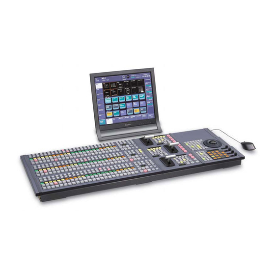
Page 1: Control Panel: Example Configuration
MVS-8000/8000SF System (With CCP-8000 Series Center Control Panel) User’s Guide Multi Format Switcher System [English] Volume 1 1st Edition (Revised 7) Software Version 5.00 and Later... - Page 2 NOTICE TO USERS © 2001 Sony Corporation. All rights reserved. This manual or the software described herein, in whole or in part, may not be reproduced, translated or reduced to any machine readable form without prior written approval from Sony Corporation.
-
Page 3: Vol.1 Vol
Functions Newly Supported in Version 5.00 The functions newly supported in the MVS-8000 system version 5.00 are as follows. Functions relating to switcher processor Classification Functions supported Menu No. See page Vol.1 Vol.2 In an HD system, holds a maximum of 444 still 2121 –... - Page 4 Classification Functions supported Menu No. See page Vol.1 Vol.2 Setup protection Locking operation of setup menus 7317.1 Installation Automatic detection of the software that can be 7316.10 – installed on each device Assignment of side flag enable/disable function 7322.1 Side flags to a cross-point button Side flag adjustments 7331.7...
- Page 5 There are some menus from which you cannot move to a different menu or which have buttons becoming inoperable depending on the operating situation. Functions Not Supported in Version 5.00 The following functions are not supported in the MVS-8000 system version 5.00. Functions relating to switcher processor...
- Page 6 Functions relating to setup Classification Functions not supported Menu No. See page Vol.1 Vol.2 Prefs/Utility buttons Assigning the command “Enabling and disabling 7324 – 331, operation from an editing keyboard” to the utility/ 7324.1 shotbox control block, or user preference buttons a) Scheduled to be supported from Version 5.10...
-
Page 7: Table Of Contents
Table of Contents Chapter 1 MVS-8000 Functions Introduction ....................19 Features of the MVS-8000 Multi Format Switcher System......22 Video Processing Flow .................24 Signal Selection .....................25 Basics of Signal Selection ..............26 Bus Selection ..................26 Signal Assignment and Selection ............28 Signal Name Display................31 Transitions.....................32... - Page 8 Frame Memory .....................78 Overview ....................78 Frame Memory Functions ..............79 Color Backgrounds..................84 Copy and Swap .....................85 Side Flags.......................89 Overview ....................89 Side Flag Settings ..................89 Wipe Action on Images With Side Flags ..........90 DME Wipe Action for an Image With Side Flags ........91 Video Process ....................93 Video Process Adjustments of a Primary Input Signal ......93 Video Process Adjustments on a Particular Bus ........93...
- Page 9 Effect Execution ..................165 Master Timelines .................166 Snapshots.....................167 Snapshot Types..................167 Snapshot Attributes ................168 Utility ......................170 Shotbox ......................171 Setup ......................172 Overview of Setup................172 System Setup ..................172 Saving and Recalling Setup Data ............177 Panel Setup ..................178 Switcher Setup..................181 DME Setup ..................184 Setup Relating to DCU Input/Output ..........185 Setup Relating to the Router Interface and Tally Interface....185 Simple Connection to MKS-8080/8082 AUX Bus Remote Panel..187 Files ......................188...
- Page 10 Flexi Pad Control Block (Standard Type) ...........226 Key Control Block................228 Device Control Block (Trackball) ............232 Device Control Block (Joystick) ............236 Keyframe Control Block ..............237 Numeric Keypad Control Block............240 Fade to Black Control Block ...............242 Auxiliary Bus Control Block (for AUX Buses) ........243 Auxiliary Bus Control Block (for Router Control) ......246 Menu Control Block ................249 Memory Card/USB Adaptor Block .............250...
- Page 11 Executing a Transition With the Fader Lever (Manual Transition) ..305 Combinations of Auto and Manual Transitions ........306 Non-Sync State..................306 Fader Lever Operation in Bus Fixed Mode.........307 Transition Preview ..................309 Independent Key Transitions ..............311 Basic Independent Key Transition Operations........311 Setting the Independent Key Transition Type by a Menu Operation..312 Setting the Independent Key Transition Rate........313 Fade to Black....................316 Fade to Black Operation..............316...
- Page 12 Key Snapshot Operations ..............366 Key Snapshot Operations Using a Simple Transition Module....368 Chapter 5 Wipes Basic Procedure for Wipe Settings ............372 Wipe Settings Menu ................372 Wipe Pattern Selection ................372 Pattern Mix ..................375 Setting Wipe Modifiers ...............377 Wipe Modify Clear................389 Wipe Settings for Independent Key Transitions ........390 Basic Procedure for Independent Key Transition Wipe Settings..390 Setting Independent Key Transition Wipe Modifiers ......391 Wipe Snapshots...................395...
- Page 13 Recalling Images .................427 Image Processing.................429 Image Output ..................432 Continuously Capturing Images (Record)...........434 Recalling a Continuous Sequence of Images (Animation)....435 Image Data Management................438 Deleting Files ..................438 Renaming Files..................439 File Backups ..................440 Restoring Files..................441 External Hard Disk Drive Access .............442 Hard Disk Formatting................443 Saving Files ..................443 Recalling Files ..................445 Chapter 8 Color Backgrounds...
- Page 14 Table of Contents...
- Page 15 Chapter 1 MVS-8000 Functions Introduction ....................19 Features of the MVS-8000 Multi Format Switcher System ....22 Video Processing Flow ................24 Signal Selection ...................25 Basics of Signal Selection ..............26 Bus Selection ..................26 Signal Assignment and Selection ............28 Signal Name Display ................31 Transitions ....................32 Selecting the Next Transition ..............32...
- Page 16 Relation Between DME Wipes and Other Effects ......75 DME Wipe Snapshots .................76 DME Wipe Modify Clear ..............76 Frame Memory ...................78 Overview .....................78 Frame Memory Functions ..............79 Color Backgrounds ..................84 Copy and Swap ...................85 Side Flags .....................89 Overview .....................89 Side Flag Settings ................89 Wipe Action on Images With Side Flags ..........90 DME Wipe Action for an Image With Side Flags ......91 Video Process ....................93...
- Page 17 Control of GPI Devices ..............146 VTR/Disk Recorder/Extended VTR Control ........147 Regions and Registers ................150 Regions ....................150 Registers ....................151 Keyframes ....................153 Effects ....................153 Saving and Recalling Effects ............154 Effect Attributes ................154 Effect Editing ..................154 Time Settings ..................156 Paths ....................159 Effect Execution ................165 Master Timelines ................166 Snapshots ....................167 Snapshot Types ..................167...
- Page 18 Macros .......................193 Overview ...................193 Macro Creation and Editing ..............195 Macro Execution ................198 Macro Editing Using Menus .............199 Macro Attachment ................200 Color Corrector ..................204 Simple P/P Software .................208 Overview ...................208 Restrictions on Use ................208...
-
Page 19: Introduction
Introduction This manual is the User’s Guide for the MVS-8000/8000SF Multi Format Switcher system. The MVS-8000 and MVS-8000SF have different numbers of M/E banks and input/output signals, but are otherwise functionally identical. This manual refers to these generically as the “MVS-8000 system,” and describes principally the operation of the system using the CCP-8000 series of center control panels. -
Page 20: Related Manuals
8000ASF system, these may be noted specifically in the relevant place. b) Where differences between the MVS-8000/8000SF system and MVS-8000A/8000ASF system are noted, these are referred to as “MVS-8000 (system)” and “MVS-8000A (system).” System nomenclature The following terms are used for systems, depending on the combination of installed options, and the signal format. - Page 21 • MVE-9000-C Operation Manual • MVE-9000-C Installation Manual CCP-8000 Center Control Panel Pack • CCP-8000 Operation Manual • CCP-8000 Installation Manual DCU-8000 Device Control Unit Pack • DCU-8000 Operation Manual • DCU-8000 Installation Manual DCU-2000 Device Control Unit Pack • DCU-2000-C Operation Manual •...
-
Page 22: Features Of The Mvs-8000 Multi Format Switcher System
DME functionality. Powerful external device interfaces By connecting to a Sony routing switcher or similar, a large system can be built. From the control panel, it is also possible to operate other equipment, including VTRs and disk recorders. - Page 23 Powerful frame memory functions In an MVS-8000 system, an HDTV system can hold 58 still image frames (88 frames in 720p/59.94 format), and an SDTV system can store 222 frames in memory, while up to eight frames can be recalled and used simultaneously.
-
Page 24: Video Processing Flow
Video Processing Flow The following illustration shows the flow of operations for carrying out a transition on an M/E bank or the PGM/PST bank. Select current background video (page 25) Select next transition (page 32) Background Keys 1 to 4 Select new background video (page 25) Make key settings (page 46) Select transition type (page 39) -
Page 25: Signal Selection
Signal Selection You carry out signal selection with the cross-point buttons in the cross-point control block of each M/E bank or the PGM/PST bank, and the buttons in the auxiliary bus control block. The number of buttons in each cross-point row may be 16, 24, or 32, but here the description is of the 32-button case as an example. -
Page 26: Basics Of Signal Selection
Basics of Signal Selection Each of the M/E banks, PGM/PST bank and auxiliary bus control block has 32 cross-point buttons and three reentry buttons (four in the case of the auxiliary bus control block). These buttons are identified by numbers common to all of the banks and block, and a signal is assigned to each number. - Page 27 Bank Bus name Cross-point Delegation operation button row PGM/PST Program bus Program row – Preset bus Preset row – DSK 1 bus DSK1 row Turn off the [DSK3] button DSK 2 bus DSK2 row Turn off the [DSK4] button DSK 3 bus DSK1 row Turn on the [DSK3] button DSK 4 bus...
-
Page 28: Signal Assignment And Selection
Bank Bus name Cross-point Delegation operation button row Auxiliary AUX1 to AUX48 buses 1st row, 2nd row Turn on the appropriate bus control buttons in accordance with MONITOR 1 to block the signal assignment MONITOR 8 buses made in the Setup menu. Frame memory source 1 and frame memory source 2 buses... - Page 29 In addition to the signals input to the PRIMARY INPUTS 1 to 80 connectors on the rear panel of the switcher, you can also select signals generated within the switcher. Each button has assigned to it a video signal and a key signal, forming a pair. You can set these video and key combinations in a Setup menu.
- Page 30 Switching button numbers The rightmost (32nd) button functions as a shift button. (The shift button function can be disabled in a Setup menu.) When selecting the signals of button numbers 1 to 31, press the cross-point button for the desired signal. To select button numbers 32 to 62, hold down the shift button, and press the cross-point button for the desired signal.
-
Page 31: Signal Name Display
Auxiliary bus control block button numbers ([2ND] button lit) Button Number when the shift Number when the shift button is not pressed button is pressed From the left end to the 31st 1 to 31 32 to 62 button Reentry buttons 121 to 124 125 to 128 Signal Name Display... -
Page 32: Transitions
Transitions In the M/E banks and PGM/PST bank, the switch from the current video stream (appearing on the corresponding program monitor) to a new video stream is referred to as a transition. Selecting the Next Transition To execute a transition, it is first necessary to decide how the image will be changed as a result of the transition. - Page 33 Inserting and deleting a key You can insert one or more of the four keys (downstream keys on the PGM/ PST bank). If you select a key which is already inserted, the transition will delete the key. A simultaneous combination of deleting and inserting keys is also possible. Key 1 Insert Delete...
- Page 34 Simultaneously changing the background and keys You can change any of the four keys (downstream keys on the PGM/PST bank) and the background at the same time. Key 1 Transition Key 2 Changing the background and key 2 simultaneously Key 1 Transition Key 2 Key 4...
-
Page 35: Independent Key Transitions
The key priority values go from 1 to 4, with a higher priority key being “in front” as seen on the screen. Priority sequence on the screen Independent Key Transitions What is an independent key transition? In addition to common transitions, it is possible to carry out independent transitions on the keyers of the M/E banks and PGM/PST bank. - Page 36 Effect of a common transition In the case shown in the previous illustration, carrying out a common transition produces the following change in the image. Same wipe is applied to Transition type: wipe background and key. Effect of a common transition Effect of use with an independent key transition The key is inserted with an independent key transition as the background changes with a common transition, providing the following result.
- Page 37 Simultaneous execution If the [AUTO TRANS] buttons for the two transitions are pressed simultaneously, the following is the result. Note that in both cases the common transition is a wipe and the independent key transition is a mix (dissolve). Deleting a key with simultaneous transitions: With the key inserted, it is deleted simultaneously with the two transitions.
- Page 38 Time offset execution with the key inserted: With the key inserted, it is deleted with the two transitions acting with a time offset. Whichever button is pressed first, when the common transition completes, even if the independent key transition is still not completed, the two end simultaneously.
-
Page 39: Transition Types
Example 1: When the independent key transition [AUTO TRANS] button is pressed later The transition Common transition Independent key completes with the (wipe) start transition (mix) key deleted. start Example 2: When the common transition [AUTO TRANS] button is pressed later The transition Independent Common... - Page 40 NAM (non-additive mix) In this dissolve, the current video and new video signals are compared, and the signal with the higher luminance level is given priority in the output. The current video is maintained at 100% output for the first half of the transition as the new video increases progressively to 100%, then the current video is progressively reduced from 100% to zero in the second half with the new video maintained at 100% output.
- Page 41 • You can also make a setting such that when a preset color mix is completed, the next transition switches to the previous transition type automatically. This is called “one-time mode.” When only the background is changed Current video Color matte New video Preset color mix (changing background only) When a key is inserted...
-
Page 42: Executing A Transition
Wipe A wipe replaces the current video by the new video according to a predetermined pattern. This transition type can also be selected for an independent key transition. For details, see “Wipes” (page 56) and Chapter 5 “Wipes” (page 371). DME wipe Using a DME effect, it is possible to obtain a transition to a new image from the current image, as in a wipe. -
Page 43: Manual Transitions
You can set the transition rate in advance. (See “Setting the Transition Rate” (page 298).) Manual transitions Using the fader lever, you can manually control the progress of the transition. Moving the fader lever from one end of its travel to the other completes the transition. -
Page 44: Transition Preview
Transition preview With the preview output of the M/E banks and PGM/PST bank, you can check the effect of a transition in advance. To carry out a transition preview, press the [TRANS PVW] button in the transition control block. (See “Transition Preview”... - Page 45 For details of the setting, see “Settings Relating to Video Switching (Transition Menu)” in Chapter 16 (Volume 2). Transitions...
-
Page 46: Keys
Keys A key is an effect in which a part of the background image is replaced by an image or superimposed text. The signal determining how the background is cut out is termed “key source,” and the signal that replaces the cut-out part is termed “key fill.”... -
Page 47: Chroma Key
Clean mode In a luminance key, linear key or color vector key, you can enable the clean mode. When the clean mode is on, the key source does not affect the key fill, which is added unchanged to the background. This improves the keyed image quality, but means that the part of the key fill signal which is not to be inserted must be completely black, or it will color the background. - Page 48 Normal mix: The foreground is cut out with the key signal, and then combined with the background, which has also been cut out with the key signal. Additive mix: The background, which has been cut out with the key signal, is combined with the unshaped foreground.
- Page 49 Angle Reference color specified by Hue setting Crop Range of colors creating the key signal Range of colors remaining (to be replaced by background signal) as foreground a) The Crop and Angle values do not change even if you use the auto chroma key function. Window adjustment Y balance In normal chroma keying, the key signal is based on the chrominance...
-
Page 50: Key Modifiers
For details of video adjustment operations and the adjustment items, see “Chroma Key Adjustments” (page 330). Wipe pattern key This uses the wipe pattern selected for a transition as the key source. Key wipe pattern key This uses the wipe pattern selected for an independent key transition as the key source. - Page 51 Border This applies a uniform width border to the edge of the key. You can adjust the border width and density. You can also enable the separate edge function, and adjust the top, bottom, left, and right border widths separately. Drop border This applies a border below and to the right for example, of the key.
- Page 52 Outline This uses the outline of the original key as the key. You can adjust the width and density of the outline. You can also enable the separate edge function, and adjust the top, bottom, left, and right outline widths separately. Emboss This applies an embossing effect to the outline of the key.
- Page 53 • When the edge type is normal with soft edge being on • When Fine Key is on Edge fill When a border, drop border, or shadow modifier is selected, you can select a signal to fill these edge effects. The edge fill may be either the signal from the dedicated color matte generator, or the signal currently selected on the utility 1 bus.
-
Page 54: Key Memory
mask source. When the box generator is selected, a rectangular mask is formed. You can adjust the positions of the four sides of the box separately. When the pattern generator is selected, you can select the pattern and apply modifiers. Sub mask: This uses the wipe generator signal or the signal selected on the utility 1 bus on the M/E or PGM/PST bank, as the mask source. -
Page 55: Blink
Blink The blink function provides the following effects. Key blink: The key is inserted and deleted at the specified frequency. You can also set the frequency and the proportion of the cycle for which the key is inserted. Edge blink: Key fill and key edge fill are interchanged at the specified frequency. -
Page 56: Wipes
Wipes A wipe is a transition from the current video stream to a new video stream, using a wipe pattern. Changing the background by means of a wipe is referred to as a “background wipe,” and inserting or deleting a key with a wipe is termed a “key wipe.” There are two types of wipe: those that can be selected in a common transition, and those that can be selected in an independent key transition. - Page 57 Note It is not possible to apply a pattern mix to an independent key transition. For details, see “Pattern Mix” (page 375). Types of pattern mix There are four ways in which patterns can be combined in a pattern mix, as follows.
- Page 58 Parameter settings Main pattern at 100% Start: Point in the course of the transition at which the main pattern Sub pattern at 100% is at 100% End: Point in the course of the transition at which the sub pattern is at 100% 0.00 100.00 Transition (0.00 - 100.00)
-
Page 59: Wipe Pattern Variation And Modifiers
Main and sub modifier link function When carrying out a pattern mix, it is possible to link the modifier settings for the main pattern and sub pattern. There are two modes for this function. FULL LINK (fully linked) mode In this mode, all modifier settings are the same for the main pattern and sub pattern. - Page 60 Split This splits the pattern, making the parts of the wipe move in opposite directions. Split off Split on The parameter Split No specifies the number of splits. The parameter Spacing specifies the spacing between adjacent patterns. Edge You can apply a border to the pattern, soften the edges, or soften the applied border.
- Page 61 Positioner You can move the wipe pattern to any position. Positioner off Positioner on • The parameter H Position controls the horizontal position of the pattern. A negative value moves the pattern to the left, and a positive value moves the pattern to the right.
- Page 62 Speed Through the course of the transition the wipe pattern rotates at a fixed specified speed. The parameter Speed determines the speed of pattern rotation. A value of –100.00 of the parameter Speed corresponds to one turn per second counterclockwise; a value of +100.00 corresponds to one turn per second clockwise.
-
Page 63: Aspect Ratio
Aspect ratio You can freely change the aspect ratio of the pattern. Aspect off Aspect on (a horizontal stretch) A negative value of the parameter Aspect stretches the pattern vertically; a positive value stretches the pattern horizontally. Pattern replication (“Multi”) The same pattern can be repeated horizontally and vertically or both, up to 63 times. - Page 64 1: All replications in the same orientation 2: Even-numbered rows staggered 3: Even-numbered columns and rows inverted 4: Even-numbered columns and rows inverted, and even-numbered rows staggered Pairing This slits the pattern into multiple strips, making it like a venetian blind. Pairing off Pairing on H: Create slits in the horizontal direction.
- Page 65 Modulation The pattern signal can be modulated, giving waves on the horizontal or vertical edges, or radially. The parameter Shape determines the form of the modulation. 1: sine wave, 2: triangular wave, 3: rectangular wave Note When using 1080PsF mode in an HD system, the modulation function is not available.
- Page 66 Fringe This modulates the pattern, applying waviness in the radial direction to edges. The parameter Speed determines the speed of waves. A value of –100.00 generates the maximum counterclockwise speed of waves, and a value of +100.00 the maximum clockwise speed. Spring As the transition progresses, the edge of the pattern is subjected to barrel or pincushion distortion.
-
Page 67: Wipe Snapshots
• The parameter Magnitude determines the size and direction of the spiral. A value of –100.00 represents the maximum movement in the counterclockwise direction, and a value of +100.00 represents the maximum movement in the clockwise direction. • The parameter Wave Speed determines the speed of the lateral waves. A value of –100.00 represents the maximum speed to the left, and a value of +100.00 represents the maximum speed to the right. -
Page 68: Dme Wipes
DME Wipes A DME wipe is a wipe transition that uses a DME effect to change from one video image to the next. There are two types of DME wipe: those which can be selected for a normal transition, and those which can be selected for an independent key transition. For independent key transitions, see page 35. - Page 69 Squeeze: The new video appears squeezed over the old video, and progressively expands to cover it. (Pattern numbers: 1021 to 1031 (one-channel mode), 2621 to 2628 (two- channel mode)) Door: The new video moves like a door closing, and progressively covers the old video.
- Page 70 • Note that for an independent key transition, only the Slide, Split, Squeeze, Door, Frame in-out, and user programmable DME patterns are available. User programmable DME in transition mode For the transition mode set when creating a keyframe effect for a user programmable DME pattern, the following can be used.
- Page 71 • Example of the image change in the transition mode “Compress” First stroke Second stroke Transition mode “frame in-out” In this mode, when the first transition has completed, you can move the image with the positioner in both horizontal and vertical directions, but the image position at the transition start point and end point does not change.
- Page 72 First transition Transition start completion point Transition end Image created by interpolation Background A Background B Effect execution State before modification Transition mode “frame in-out H” This mode is specified when creating a transition effect in the horizontal direction. In this mode, when the first transition has completed, you can move the image with the positioner in both horizontal and vertical directions.
- Page 73 First transition completion point Transition start Transition end Image created by interpolation Background A Background B Effect execution State before modification Transition mode “frame in-out V” This mode is specified when creating a transition effect in the vertical direction. In this mode, in the state at completion of the first transition, you can move the image with the positioner in both horizontal and vertical directions.
-
Page 74: Dme Wipe Pattern Variation And Modifiers
At the first transition completion point, if you move the image with the positioner, the transition appears as in the following figure. First transition Transition start completion point Transition end Image created by interpolation Background A Effect execution Background B State before modification Signals forming part of the background for a DME wipe... -
Page 75: Relation Between Dme Wipes And Other Effects
In the case of a user programmable DME pattern in which a border has already been applied to the effect, the behavior is as follows. • When the DME wipe border setting is on, only part of the border applied in the effect is enabled, and that portion can be adjusted. -
Page 76: Dme Wipe Snapshots
Relation to ordinary wipes • DME wipes do not use the wipe generator built into the switcher. Therefore, during the execution of a DME wipe, you can still use a pattern produced by the wipe generator as the source for a pattern key or mask. •... - Page 77 For details of the menu operation to return the DME wipe state to that set in initial status, see “Returning to default state in function groupings” (page 275). DME Wipes...
-
Page 78: Frame Memory
Frame memory is a function whereby a frame of input video can be frozen and written to memory, for further use as material for editing. In an MVS-8000 HD system the maximum number of image frames that can be written to memory is 58 (88 frames in 720p/59.94 format), and in an SD system a maximum of 222 frames. -
Page 79: Frame Memory Functions
applies to the other pairs. When a pair of images are captured in pair mode, the image frozen in FM1 (3, 5, or 7) is referred to as the main file and the other frozen in FM2 (4, 6, or 8) is referred to as the sub file. Operation modes The frame memory has the following operation mode. - Page 80 Note When the system is powered off, any freeze images written to temporary memory are lost. Saving an image (store) You can save an image in temporary memory which has been placed with the freeze function as a file in memory. You can save a single image in a single file and apply a name of up to eight characters to the file.
-
Page 81: Image Output
Image output Moving the output image (reposition function) For up to two channels of FM1 to FM8 (one from FM1, FM3, FM5 and FM7 and the other from FM2, FM4, FM6 and FM8), you can move the output image with respect to the screen. The area of the screen around the image that has been moved is filled with black. -
Page 82: Image Data Management
• To execute the effect, you must assign the user region to which FM1 is assigned to a region selection button in the numeric keypad control block. (For details of assigning to region selection buttons in the numeric keypad control block, see “Overall Control Panel Settings (Config menu)” in Chapter 16 (Volume 2).) In the Frame Memory menu, effect creation follows the image file names. - Page 83 Memory card capacity Number of images that can be saved SD system HD system 16MB 32MB 64MB 128MB a) For all available signal formats except 720p Note that when transferring to the hard disk, there is ample capacity, so that problems such as this do not occur.
-
Page 84: Color Backgrounds
Color Backgrounds The dedicated generators generate color signals, and these can be used as color backgrounds in video effects. Color background selection There are two color backgrounds, color background 1 and color background 2, which you use by assigning to cross-point buttons. Color combinations (“color mix”) The color generators can output the result of combining two colors, which are color 1 and color 2. -
Page 85: Copy And Swap
Copy and Swap You can copy and swap the settings among the M/E-1 to M/E-3, and PGM/PST banks or between keyers. The following settings can be copied or swapped. • Overall settings for the M/E-1 to M/E-3, and PGM/PST banks •... - Page 86 Keyer copy and keyer swap You can carry out copy and swap operations among the 16 keyers listed in the following table. Target bank Target keyer Target data M/E-1 Keys 1 to 4 Key settings excluding the following data M/E-2 items: M/E-3 •...
- Page 87 Target bank Target data M/E-1 DME wipe settings. M/E-2 It is not, however, possible to carry out copy or swap involving M/E-3 independent key transition DME wipe settings. PGM/PST DME wipe copy and DME wipe swap in the independent key transition control block You can copy and swap the DME wipe settings among the 16 keyers listed in the following table.
- Page 88 Target bank Target keyer and data DME ch1 to ch8 • Background • Border • Sepia • Light • Shade • Drop shadow (other than DME ch4 and DME ch8) • Trail DME channel copy and swap You can copy and swap the channel data among DME channels 1 to 4 or DME channels 5 to 8.
-
Page 89: Side Flags
Side Flags Overview The term “side flags” refers to the areas to left and right of an image with aspect ratio 4:3 embedded within a 16:9 frame, when these areas are filled with a separate image selected from the utility 1 bus. (See following figure.) You can adjust the width of the side flag area. -
Page 90: Wipe Action On Images With Side Flags
Input source aspect ratio, auto side flags, and auto crop settings Aspect ratio 4:3 setting Set the input signal to aspect ratio 4:3. If set to 16:9, the side flags are disabled. Auto side flag setting This function automatically applies side flags when a 4:3 signal is selected in the cross-point control block. -
Page 91: Dme Wipe Action For An Image With Side Flags
Wipe from a 4:3 image to a 16:9 image Side flag areas 16:9 image 4:3 image (Side flags on) Wipe from a 4:3 image to another 4:3 image (when side flags are on for both images) Side flag areas Side flag areas 4:3 image (Side flags on) The circles indicate the position of the wipe pattern... - Page 92 DME wipe from a 4:3 image to a 16:9 image Wipe action using slide (No. 1001) Side flag area Auto crop off Side flag areas Auto crop on 16:9 image 4:3 image (Side flags on) DME wipe from a 4:3 image to another 4:3 image (when side flags are on for both images) Wipe action using squeeze (No.
-
Page 93: Video Process
Video Process The term “video process” is applied to adjustments to the luminance and hue of the input video signal. There are two types of adjustment, depending on the application: • Adjustment of an individual primary input signal • Image effects on a particular bus Note These types of adjustment may be carried out independently. -
Page 94: Video Process Memory
Making the adjustments Adjust VIDEO GAIN, Y GAIN, BLACK LEVEL, C GAIN, and HUE DELAY in the following menus. Applicable bus Menu used for operation See page M/E-1 to M/E-3 Key fill buses for keys M/E-1 to M/E-3 menus page 352 banks 1 to 4 Background A and B... -
Page 95: Digital Multi Effects (Dme)
MVE-9000 Multi Format DME Processor The MVE-9000 is a “Digital Multi Effects” with multi-format support. Two interfaces are available for the MVE-9000: a dedicated interface (MKE- 9020M) for use in an MVS-8000 series switcher, and an SDI interface (MKE- 9021M). Digital Multi Effects (DME) -
Page 96: Three-Dimensional Transformations
Note When using the SDI interface, the following operations are different from when uing the dedicated interface. • Setting the input signals from the switcher to the MVE-9000 (AUX bus outputs), and signals returned to the switcher as primary inputs (reentry inputs). - Page 97 Source coordinate space Target coordinate space Source coordinate space and target coordinate space For example, as shown in the following figure, the image moves in a different direction when you move it along the x-axis of the source coordinate space and along the x-axis of the target coordinate space.
- Page 98 Rotation around y-axis in local coordinate space Rotation around y-axis in global coordinate space Local coordinate space and global coordinate space Three-dimensional parameters Three-dimensional parameters are x, y, and z values which define the position of an image, its axis of rotation, the position of an imaginary point of view on the image, and so on.
- Page 99 • Lower left corner of image or monitor When using SD format signals: x = – 4.00, y = –3.00, z = 0.00 When using HD format signals: x = –12.00, y = –9.00, z = 0.00 y-axis z-axis + +3(+9) x-axis –4(–12)
- Page 100 • Lower left corner of image or monitor When using SD format signals: x = −4.00, y = −2.25, z = 0.00 When using HD format signals: x = −16.00, y = −9.00, z = 0.00 y-axis z-axis + +2.25 (+9.00) x-axis –4.00 (–16.00) +4.00 (+16.00)
- Page 101 Detents The system defines points called detents at regular intervals on the three- dimensional space. Pressing the [CTR] button in the device control block sets the current three-dimensional parameter values to the closest detent points. (For details, see “Three-Dimensional Transformation Operations” in Chapter 11 (Volume 2).) The following table shows the interval between successive detents for each transformation operation mode (see page 102).
-
Page 102: Transformation Operation Modes
Resetting of parameter values set in the source coordinate space In some transformation operation modes, if you switch to the target coordinate space after setting up a three-dimensional transformation in the source coordinate space, the setting values in the source coordinate space (three- dimensional parameter values) are converted to values in the target coordinate space (source/target conversion). - Page 103 Image movement in the target coordinate space Movement on the x-axis Movement on the y-axis Movement on the z-axis Rotation Rotates the image on the x-axis, y-axis, or z-axis. The type of rotation differs depending on whether you are manipulating the image in the source coordinate space or the target coordinate space.
- Page 104 the image in the source coordinate space or the target coordinate space. (The way the image rotates around an axis is the same as in Rotation mode.) Axis Location Moves an axis of rotation in the source coordinate space. Axis movement Movement on the x-axis Movement on the y-axis Movement on the z-axis...
- Page 105 Magnification and shrinking in the target coordinate space Aspect In the source coordinate space, changes the aspect ratio in the x-axis direction and y-axis direction, either independently or simultaneously. Change of aspect ratio in Change of aspect ratio in Simultaneous change x-axis direction y-axis direction aspect ratio in x-axis...
-
Page 106: Graphics Display
Skew In the source coordinate space, change the skew of the image on the x-axis or y-axis. Change of skew on x-axis Change of skew on y-axis Graphics Display Graphics display is a function that allows you to display wire frames, coordinate axes and a grid over the current DME image, to make it easier to create effects in three-dimensional coordinate space. - Page 107 Channel ID This displays the channel number so that you can check which channel you are using, a useful feature when you are working with multiple channels. Channel IDs are displayed differently in local and global coordinate space. • In local coordinate space, the channel number is displayed along with “F” or “B”...
-
Page 108: Three-Dimensional Parameter Display
Wire frame Range displayed on normal monitor screen To automatically erase the graphic display Turn Auto Erase on. The graphic display is erased automatically whenever a keyframe is executed. It is displayed again after the keyframe ends, after the time set in Recovery Time. Flex Shadow center axis When using the Flex Shadow function (see page 111), turn Flex Shadow Axis on to display the Flex Shadow center axis. - Page 109 Border This effect adds a border to the image frame. You can adjust the width (or thickness) of the border, its color, and the softness of the border edges. Crop This effect crops away the edges of the image. You can crop the top, bottom, left, and right sides individually or all together.
- Page 110 Blur Applies a rounded blurring to the whole image. Beveled Edge This gives an image a beveled edge. You can set the edge width and color. The inner edge softness and edge boundary softness can also be set. Color Light Key Border This effect adds borders to keys or gives a key consisting of an outline only.
- Page 111 Examples of Art Edge source Gradation Matte Radial Gradation Rainbow Matte Radial Rainbow Example effect using Art Edge source [Rainbow Matte] Note The Art Edge function is not supported on the MVE-8000/8000A. Flex Shadow This effect allows a shadow to be added to the image using only one DME channel.
- Page 112 – Internal: Generate shadow using an internally generated, full-size DME key signal. • Shadow shrinking and magnification • Shadow position • Shadow color and density • Center axis of deformation • Shadow slant and perspective External Internal Note The Flex Shadow function is not supported on the MVE-8000/8000A. Wipe crop This effect crops the video image to be visible inside or outside a wipe pattern.
- Page 113 Color mix This is a combination of two colors with a pattern generator. This color mix signal can be used to fill parts such as a background or border. Color 2 Color 1 Note The Color Mix function is not supported on the MVE-8000/8000A. Multi Move Shrinks the image and lines up a number of copies vertically and horizontally.
- Page 114 Posterization Coarsens the luminance gradations of the image, for a painting-like effect. You can specify the degree of luminance coarsening. Solarization Like the Posterization effect, creates a painting-like effect, but does so by coarsening the chroma gradations of the image. You can specify the degree of chroma coarsening.
- Page 115 Sketch Provides a sketch-like effect based on the outlines of the image, using different touches such as sketch, edge color, drawing, relief, and sharp. Sketch Note The Sketch function is not supported on the MVE-8000. Metal Provides a metallic gloss like that from gold, silver, or a rainbow colored surface.
- Page 116 Dim and Fade Dim makes the picture progressively dimmer into its depths. Fade progressively makes the depths of the picture fade into the background. Fade Note The Dim and Fade functions are not supported on the MVE-8000/8000A. Glow Softens the edges of highlights, giving an effect like being struck by a soft light. Note The Glow function is not supported on the MVE-8000.
- Page 117 Effect video Effect video image (Mosaic) Video image image (Mosaic) Video image Mask (normal) Mask (invert) Notes • The Mask function is not supported on the MVE-8000. • On the MVE-8000A, the Mask function cannot be applied to both effect group 1 and effect group 2 simultaneously.
- Page 118 There are two modes: H&V and Size. You can set the size and frequency of the waves, the wave form, the amount of wave movement, and the range. In H&V mode, you can also set the wave angle. Note When 720p/59.94 signal format is used, the wave effect is not supported on the MVE-8000.
- Page 119 Twist Twists the image. You can twist the image in the horizontal or vertical direction. You can set the size and frequency of waves in the image, the wave form, the amount of wave movement, and other parameters. Ripple Applies an effect like ripples moving across the image. There are four modes: Radial, Angular, Both, and Shape.
- Page 120 Broken Glass Partitions the image like broken glass, with shards flying outward. You can set the degree of transition, the degree of randomness in the distance moved by each block, the amount of movement, the width of the partitions, the degree of randomness in partition width, the center point, the starting angle, and other parameters.
- Page 121 Split Splits the image upper and lower, left and right. You can set the degree to which the image is split, the split positions, and other parameters. Split Slide Divides the image into bars which slide alternately in reverse directions. You can set the degree of transition, the degree of randomness in the distance moved by each block, the degree of sliding, block width, block angle, and other parameters.
- Page 122 You can set the width of the original, the center position of the original, the offset of the image with fixed mirrors, the direction of the mirrors, and other parameters. Kaleidoscope Creates an image like a view into a kaleidoscope. You can set the number of blocks, the partition reference point and angle, horizontal and vertical offsets, a reflection position, and other parameters.
- Page 123 You can set the size of the circle, and make the axis of modulation vertical. Panorama Curves the upper and lower edges of the image to emphasize the sense of perspective. You can set the horizontal and vertical curve ratio, and the curve center position.
- Page 124 There are four modes: H&V, H, V, and Off. You can select the turn position, the radius of the turned portion, the amount and angle of turning, and the input video for the front and back pages. Cylinder Winds the whole image onto a cylinder. You can set the degree of winding onto the cylinder, the radius, the horizontal position of the wound image, and front and back side output for the image.
- Page 125 You can set the pattern shape and aspect ratio, the center position, the amount of movement by fragments, the curvature of the transition path, and other parameters. Swirl Swirls the image. You can set the amount of swirl, the swirl region, the amount of rotation, and the swirl center position.
- Page 126 You can set the effect starting position, the degree of expansion, the slant angle of the effect region, and trail direction, the degree to which the image disappears, the trail type and amount of stardust, and other parameters. Lighting Provides the effect of light striking the image. You can specify the intensity and color of the light and the lighting pattern.
- Page 127 Combine Shadow When there are several images, adds a flex shadow in the depth of an image or overlays multiple flex shadows. Example 1: When Flex Shadow is enabled on both of two channels. Video Video Over Over Over Under Under Under Shadow...
- Page 128 Example 2: Flex Shadow is enabled on one channel only. Video Video Over Over Over Under Under Under Shadow No combine shadow is set. Over Over Over Under Under Under Over Over Over Under Under Under Combine shadow is enabled. Combine shadow is enabled.
- Page 129 You can make the afterimages stardust trails. Keyframe Strobe Freezes the video each time the effect passes a keyframe. (See “Note” in the section “Trail.”) You can make the afterimages stardust trails. Wind This effect strobes the image at regular intervals, and moves the frozen image in a fixed direction, leaving an afterimage.
- Page 130 Adjustments to the image surface The following adjustments can be made to the image surface struck by the light. • Adjusting the brightness of the whole image • Selecting the image surface effect Flat: The image surface is unchanged, causing the selected light source to appear as the effect.
- Page 131 Image before movement Coordinate axis = Fix Texture does not move, even if DME image moves. • Texture deformations You can change the texture pattern, position, and size, and use the repetition function. The following figure shows examples of a texture pattern repeated in the X and Y directions.
- Page 132 Light source Light source Light source Parallel Point Line Whole • Linking and unlinking image and spotlight The spotlight can move together with a DME image, or be fixed in place. Source: Place the light source in source coordinate space. The spotlight is linked and moves when the image moves.
- Page 133 Background Spotlight Foreground No effect FRGD selected BKGD selected Both selected • Surface Flat For the currently selected light source only, you can forcibly make the image surface effect flat. This is effective when you have selected texture as image surface effect and want a flat effect for one light source only.
- Page 134 • Fill blending modes Specifies the way in which the light is blended with the image. Mix: Light as if reflected from a mirror. The light can be given a color. Multiply: Light as if reflected from a dull surface (diffuse reflection). Relation between test spheres and parallel rays The following figure shows an example of the effect of parallel rays on a test sphere.
- Page 135 The unit of these direction parameters is the number of rotations, with 360° (1 rotation) expressed as 1.00, in the same way as 3D rotation parameters. The following relationships apply in the example shown in the figure. Parameter Setting Angle Longitude 0.12 45°...
- Page 136 Note The user texture pattern function is not supported on the MVE-8000/8000A. For details of spotlighting, see page 129. For details of how to create a user texture pattern, see “Adding user texture patterns” in Chpater 16 (Volume 2) , and for how to select a pattern once created, see “To select a texture pattern”...
-
Page 137: Interpolation
Invert Inverts the input video signal and/or key signal horizontally or vertically. You can make separate settings for the front and back. Horizontal inversion Input signal Vertical inversion Inversion of input signal Interpolation Specifies the methods used for interpolation processing of input video signals and input key signals. -
Page 138: Key Density Adjustment
– MVE-8000/8000A: 480i/59.94, 576i/50 – MVE-9000: 480i/59.94, 576i/50, 1080i/59.94, 1080i/50, 1080i/60 • The anti-moire filter function is only effective when the MVE-8000/8000A is used in an HD system. Key Density Adjustment You can adjust the key density for the key signal input to the DME. Key Source Selection You can select either the key signals received from the switcher or the key signals generated in the DME for application to the front and back of the image... - Page 139 Combination of channel 1 (Ch1) and channel 2 (Ch2) Combiner Combination of Ch1, Ch2, and Ch3 Combiner Digital Multi Effects (DME)
- Page 140 Combination of Ch1 and Ch2 / combination of Ch3 and Ch4 Combiner Combiner Combination of Ch1, Ch2, Ch3, and Ch4 Combiner Mixing Ch1 and Ch2 Mix1 If the Mix1 setting is 70, the proportion of the channels in the mixed portion in the previous illustration is as shown in the following table.
- Page 141 Combination Indication in figure Ch1 and Ch2 Mixing Ch1, Ch2, and Ch3 Mix1 Mix2 If the Mix1 setting is 70 and the Mix2 setting is 40, the proportions of the channels in the mixed portions in the previous illustration are as shown in the following table.
- Page 142 If the Mix1 setting is 70 and the Mix2 setting is 40, the proportions of the channels in the mixed portions in the previous illustration are as shown in the following table. Combination Indication in figure Ch1 and Ch2 – –...
- Page 143 Combinations of Ch2, Ch3, and Ch4 Upper side: Ch2 image Side V: Ch3 image Side H: Ch4 image You can adjust the height of the brick, the overlap between the three images and the way to insert the side images. Shadow This effect gives the image a shadow.
-
Page 144: External Devices
The following is an outline of external device control. For external device control operations, see Chapter 12 “External Devices” (Volume 2). For details on the devices that can be connected, consult your Sony representative. Shared Functions for External Device Control... -
Page 145: Control Of P-Bus Devices
The following keyframe functions cannot be used. • KF LOOP, EFFECT LOOP, REVERSE, NORMAL/REVERSE • PATH Saving to registers Set the data for controlling external devices in the Device menu. You can save the set data in keyframe, snapshot, or shotbox registers. You can recall the register in which the data is saved, and carry out operations on it with the keyframe control block. -
Page 146: Control Of Gpi Devices
P-Bus trigger mode actions The actions that can be used in P-Bus trigger mode are as follows. • Store • Recall • Trigger For details of the buttons assigned to each action, see Chapter 12, “External Devices” (Volume 2). P-Bus timeline At a keyframe point on the P-Bus timeline, you can set an action (setting what action command is output to which device). -
Page 147: Vtr/Disk Recorder/Extended Vtr Control
GPI output port. VTR/Disk Recorder/Extended VTR Control In the MVS-8000 system, for up to 12 VTRs, disk recorders or Extended VTRs connected to a DCU, you can carry out the following manual operations and timeline settings. - Page 148 • Setting a start point: For each selected VTR/disk recorder/Extended VTR you can set the start point timecode value as keyframe data. • Setting a stop point: For each selected VTR/disk recorder/Extended VTR you can set the stop point timecode value as keyframe data. •...
- Page 149 Recalling disk recorder/Extended VTR files Material held on a disk recorder/Extended VTR is managed in units of files. You can recall a file to play it back. (In the case of an Extended VTR, the register number is recalled.) Accessing the file list Before playback and suchlike operations on a disk recorder/Extended VTR, it is first necessary to display a list of the disk recorder files on the DCU.
-
Page 150: Regions And Registers
Regions and Registers Regions The term “region” refers to some sort of functional block of the system. When saving or recalling snapshot registers and effect registers, or creating or editing effects, you first select the region to which the operation applies. You can also select multiple regions simultaneously. -
Page 151: Registers
Reference region When multiple regions are selected, only one region appears in the displays for menu and numeric keypad operations. This is called the “reference region.” The reference region is determined according to the following precedence. M/E1 >M/E2 >M/E3 >P/P >USER1 > USER2 > USER3 > USER4 >USER5 >... - Page 152 [DME1] and [DME2]. Similarly, for registers in the 300 range, select three consecutive registers. Work register This is a temporary register used when editing keyframes. When you recall an effect, it is read from the effect register into the work register, and when you save, the contents of the work register are written to the effect register.
-
Page 153: Keyframes
Keyframes A keyframe represents an instantaneous state of an image; it can be saved and recalled for reuse. Effects By arranging a number of keyframes on the time axis, and interpolating between successive keyframes, you can create an effect in which there is a continuous change from each keyframe to the next. -
Page 154: Saving And Recalling Effects
Saving and Recalling Effects To create a new effect, first recall an empty register, then create the keyframes one at a time in this register. To run an effect, it is also necessary to set the time and the path. To edit an existing effect, recall the register holding the effect, then make the changes. - Page 155 You can edit either on a keyframe within the effect, or at any point between keyframes. Insert: Insert the current image as a keyframe. Inserting a keyframe in an existing effect may change the duration of the effect (see page 157). Modify: Modify a keyframe.
-
Page 156: Time Settings
Difference in the effect of a paste operation Variable duration mode: The copied keyframe is inserted at the specified position. Constant duration mode: The copied keyframe is written over the specified position. Transition mode You can use an effect created with keyframes as a DME wipe pattern on the switcher. - Page 157 The effect duration may also be changed by inserting or deleting keyframes. Changes in the effect duration caused by inserting a keyframe • When the effect is stopped on a keyframe, inserting a keyframe increases the effect duration by the duration of the inserted keyframe. •...
- Page 158 Changes in the effect duration caused by deleting a keyframe • When the effect is stopped on a keyframe, a delete operation deletes the keyframe, and reduces the effect duration by the duration of the deleted keyframe. • When the effect is stopped between two keyframes, a delete operation deletes the preceding keyframe, and reduces the effect duration by the duration of the deleted keyframe.
-
Page 159: Paths
Delay setting You can set the delay from the time of executing an operation to run the effect, and the effect actually starting (that is, the delay until the first keyframe). You can make this setting in the keyframe control block. (See “Time Settings” in Chapter 13 (Volume 2).) Note that changing the delay does not alter the duration of the effect. - Page 160 Item Paths that can be set Wipe/DME Wipe Overall path settings for items relating to wipes and DME wipes are made simultaneously. Wipe Wipe/DME Wipe All Wipe Path for wipes DME Wipe Path for DME wipes Trans – Transition path for each M/E and P/P bank User1 to User8 menus The items that can be adjusted depend on the settings in the Setup menu.
- Page 161 Item Paths that can be set Color Bkgd Overall path settings for color backgrounds are made simultaneously. Color Bkgd All Color Bkgd 1 Paths for color background 1 Color Bkgd 2 Paths for color background 2 Overall path settings for color corrector CCR All CCR 1 Path for color corrector 1...
- Page 162 Item Paths that can be set Skew Overall path settings for items relating to skew are made simultaneously. Skew All Skew X, Skew Y Paths for the x- and y-axes Aspect Path for aspect ratio Pers Overall path settings for items relating to perspective are made simultaneously.
- Page 163 Item Paths that can be set Axis Loc Overall path settings for items relating to image rotation axis are made simultaneously. Axis All Axis X, Axis Y, Axis Z Paths for the x-, y- and z-axes DME Effect menu Item Paths that can be set Effect All Overall path settings for DME effect items are...
- Page 164 Item Paths that can be set Light Overall path settings for lighting items are made simultaneously. Light All Lighting Path for lighting Spot Lighting Path for spotlighting Trail Path for trails In/Out Overall path settings for items relating to input/ output are made simultaneously.
-
Page 165: Effect Execution
CW: The hue changes in a clockwise direction as seen on a Vectorscope. CCW: The hue changes in a counterclockwise direction as seen on a Vectorscope. Short: The hue changes in whichever of the clockwise and counterclockwise directions is shorter. Long: The hue changes in whichever of the clockwise and counterclockwise directions is longer. -
Page 166: Master Timelines
Master Timelines You can save the regions selected for a keyframe effect and the register numbers saved in the regions in a master timeline register so that operation can be applied to two or more regions at a time. To save master timeline registers, use the numeric keypad control block or menu;... -
Page 167: Snapshots
Snapshots The term “snapshot” refers to a function whereby the various settings required to apply a particular effect to an image are saved in memory as a set of data, for recall as required, to recover the original state. You can carry out snapshot operations using the numeric keypad control block, the Flexi Pad control block in each of the M/E-1 to M/E-3 and PGM/PST banks, and the Snapshot menu. -
Page 168: Snapshot Attributes
Snapshot Attributes An individual snapshot may also have attached special conditions relating to switcher or DME operation when the snapshot is recalled. These conditions are called “attributes” of the snapshot, and can be added when the snapshot is saved or recalled. Types of attribute There are five snapshot attributes, as follows. - Page 169 Attribute Region M/E-1, M/E-2, M/E-3, and USER 1 to USER 8 DME 1 to DME 8 PGM/PST Key disable Effect dissolve Auto transition GPI outputs Attribute display You can view the attributes of a snapshot in the Snapshot menu. For more details, see “Snapshot Operations in the Menus” in Chapter 14 (Volume 2).
-
Page 170: Utility
Utility The utility function refers to a function whereby you can assign an arbitrary action or a shortcut for frequently used menu to a particular button, then instantly recall the action or menu by pressing the button. The functions you can assign include menu shortcuts, enabling/disabling functions (recalling utility commands), and recalling (shotbox registers or macro registers). -
Page 171: Shotbox
Shotbox The term “shotbox” refers to a function whereby for each specified region any snapshot or keyframe effect can be recalled simultaneously. The simultaneous recall setting data such as region names, snapshot numbers and keyframe effect numbers are stored in “registers.” There are 99 registers for each control panel. -
Page 172: Setup
Setup Overview of Setup Various settings are required, in order to operate the switcher, control panel, DME, external devices, and so on, connected together in a single system. This is referred to as “setup,” and you can carry out the setup operations from the Engineering Setup menu. - Page 173 Operation mode setting • Single Proc mode: The control panel controls a single switcher and up to two DMEs. • Single Simul mode: See “Special system setting (Single Processor Simul mode)” (page 173). • Dual Simul mode: The control panel controls two switchers and DMEs simultaneously.
- Page 174 The actual operation is linked between the top and bottom rows of the table (e.g. M/E-3 and M/E-1), but the common setting values cannot be used between the two screen aspect ratios. The edges of the screen, for example, differ between 16:9 and 4:3. For image operations in the device control block, first make the settings separately on the different channels.
- Page 175 Signal format Input reference signal Tri Sync Black burst 1080PsF/29.97, 59.94 Black Burst 59.94 Sync 59.94 1080i/59.94 1080PsF/25, 1080i/50 Black Burst 50 Sync 50 1080PsF/23.976 47.952 Black Burst 59.94 Sync 59.94 1080PsF/30, 1080i/60 – 1080PsF/24 – 720p/59.94 59.94 Black Burst 59.94 Sync 59.94 720p/50 –...
- Page 176 Autoload function Switch on or off the function to automatically load predetermined register data or frame memory image data at power on. Set the data to be read in the File menu. System reset and memory initialization (Initialize) • Reset: Reset to state after powering on. •...
-
Page 177: Saving And Recalling Setup Data
Saving and Recalling Setup Data Hard disk / memory card User setup data Load Save File menu: File menu: [Save] [Load] Current setup data (If in Resume mode, settings data is saved.) Store Initialize In Custom mode, power on or reset Setup Setup menu: menu:... -
Page 178: Panel Setup
each device is recalled when a reset is made or the power is turned back on. (See “Selecting the start up state (Start Up)” (page 175).) Note that the setup data in RAM can also be saved to the control panel hard disk or memory card. - Page 179 – For each table, specify whether the rightmost cross-point button in each row is used as a shift button, and the operation mode when it is used as a shift button. – For the [SHIFT] button in the cross-point control block and for each table, select the mode in which this is a shift button dedicated to the source name displays, or the mode in which it is a shift button for all buses.
- Page 180 disabling functions (recalling utility commands) and recalling shotbox registers or macro registers. External device connections (Device Interface) • GPI Input: Set the GPI input ports and trigger type, and make the action settings. • GPI Output: Set the GPI output ports and trigger type, and make the action settings.
-
Page 181: Switcher Setup
• Flexi Pad: Carry out Flexi Pad settings. Specify the delegation selection coupling, and display mode for the LCD buttons. • Custom Button: Set the following button operation modes. – [ALL] button for next transition selection – [AUTO TRANS], [TAKE] or [FTB] button during auto transition execution –... - Page 182 – Multi-program mode: Increase the number of M/E or P/P programs, and assign any of the following to the maximum of six outputs (Out1 to 6). (M/ E Output Assign) Program outputs 1 to 4, preview output, key preview outputs 1 and 2, clean output.
- Page 183 • Through Mode: Enable or disable through mode. Through mode can be enabled for AUX1 to 48 outputs, M/E and PGM/PST program outputs, and clean output. • Safe Title: Enable or disable safe title, and carry out settings for box 1 and 2 and cross.
-
Page 184: Dme Setup
Link settings (Link) • Internal Bus Link: Make a setting of the bus link function that links together two buses internal to the switcher. • GPI Link: Make settings for linking any cross-point buttons or [CUT] and [AUTO TRANS] buttons in the cross-point control block and GPI output ports. -
Page 185: Setup Relating To Dcu Input/Output
Interface with external devices (Device Interface) • Editor Protocol: Set the protocol to be used on the Editor port. • Editor Port Setting: Make settings relating to the control of the four editor ports installed in the DME. • GPI Input: Set the GPI input ports and trigger polarities, and make the action settings. - Page 186 Tally interface setup (Tally) Group tally settings (Group Tally) • Tally Group: Select the group tally (Gp1 to 4 or Gp5 to 8) which can be used. (For the parallel tally, all groups can be used regardless of this setting.) •...
-
Page 187: Simple Connection To Mks-8080/8082 Aux Bus Remote Panel
Simple Connection to MKS-8080/8082 AUX Bus Remote Panel To connect the MKS-8080/8082 AUX Bus Remote Panel to a CCP-8000 Center Control Panel using an S-Bus data link requires a BKPF-R70A Routing Switcher Controller Board or similar primary station and various settings for connection. -
Page 188: Files
Files You can save register data, including setup information and snapshot information, as a file on a hard disk or memory card, and recall it as required. You can operate on individual files or registers, or together in a batch. Regarding frame memory, it is possible to capture image data stored in an external device into frame memory. - Page 189 Importing or exporting files to or from frame memory Import: Import a file in a different format from hard disk or memory card into frame memory after changing its format. Export: Export a file in a register to hard disk or memory card after changing its format.
- Page 190 720 pixels 487 pixels Position of small picture Parts discarded when image is too large Section filled with black for a small picture No pixel ratio conversion is performed when images are imported for the SDTV format. When the signal format is 480i/59.94, if you create an image with a size of 720 ×...
-
Page 191: Directory Operations
Signal format × Image size (H 1080i/50 × 1920 1080 1080i/59.94 1080PsF/23.976 1080PsF/24 1080PsF/25 1080PsF/29.97 720p/50 × 1280 720p/59.94 Directory operations You can create a new directory within a hard disk or memory card, and carry out other operations, such as renaming and deleting. For details of operations, see “Directory Operations”... - Page 192 For the on/off setting of the autoload function, see “Selecting the State After Powering On (Start Up Menu)” in Chapter 16 (Volume 2). For details of saving operations, see “Saving Files Recalled by Autoload” in Chapter 17 (Volume 2). Files...
-
Page 193: Macros
Macros Overview The term “macro” refers to the function whereby a sequence of signal selections and other operations on the control panel is saved as data in memory, so that it can be recalled as required to automatically execute the same sequence of operations. - Page 194 Control block Event Transition control block • Auto transition and cut for the transition execution section • Auto transition and key on/off for the independent key transition execution section • Next transition setting • Transition type selection • Pattern limit on/off •...
-
Page 195: Macro Creation And Editing
Control block Event Device control block • VTR/disk recorder/Extended VTR start point setting • VTR/disk recorder/Extended VTR playback • VTR/disk recorder/Extended VTR stop • VTR/disk recorder/Extended VTR cue-up • VTR/disk recorder/Extended VTR start point setting • VTR/disk recorder/Extended VTR playback •... - Page 196 Creating a macro To include all information associated with an operation when registering a macro event When registering an auto transition operation as an event, you can register the auto transition event to include the transition rate and background A/B bus selection status.
-
Page 197: Editing A Macro
Editing a macro You can carry out the following macro editing operations. Event insertion Insert the control panel operation as an event in a macro. Event modification Modify any event. You can modify all events within a macro, or events within a specified range in a single operation. -
Page 198: Macro Execution
Recall macro register 2, and Recall register 1. move to another event. Macro being edited (register 2) Newly recalled macro (register 1) Copy contents of register 1 and add after current event (register 2). Contents of register 1 remain unchanged. Macro Execution To execute a macro, recall the register in which the macro is held. -
Page 199: Macro Editing Using Menus
Step execution (requires a Setup menu setting) By selecting step execution mode in the Setup menu, you can make macro execution pause every time an event is executed. Take operation When a paused macro is restarted, this is referred to as a “Take” operation. Macro take operation using a GPI input You can carry out a macro take operation using a GPI input on the control panel and DCU. -
Page 200: Macro Attachment
You can also create a new macro. Macro Attachment Macro attachment is a function whereby a macro register is assigned to a control panel button or a particular position of a fader lever, linking the execution of the button function or a fader lever operation with a macro execution. - Page 201 Block Button • Background A row cross-point buttons (page 218) PGM/PST or M/E bank • Background B row cross-point buttons (page 218) • Key 1 bus cross-point buttons (page 218) • Key 2 bus cross-point buttons (page 218) • Key 3 bus cross-point buttons (page 218) •...
- Page 202 macro is executed, the event is only replayed if the key state matches the saved state. (Example: For a macro with an event that deletes a key, when the macro is executed, if the key is inserted it is deleted, but otherwise nothing occurs as concerns keying.) b) Cross-point buttons of the bus assigned by AUX delegation setting.
- Page 203 Displaying the macro attachment list You can display the macro attachment settings in the form of a list in the menu display to check them. Macros...
-
Page 204: Color Corrector
Color Corrector The color corrector enables video signal color correction (black balance/white balance adjustment, gamma correction, knee correction, etc.). Note To use the color corrector function requires the MKS-8420M Color Corrector Board. The color corrector includes the following functions. Input video processing Carrying out the following corrections to a YUV signal before conversion to an RGB signal. -
Page 205: Secondary Color Correction
Output level Output level White balance adjustment Gamma correction Input level Input level Knee correction Black balance adjustment Unadjusted signal Adjusted signal It is also possible to mask part of the region to be corrected. Secondary color correction For the six colors R (red), G (green), B (blue), Y (yellow), C (cyan), and M (magenta), adjust the luminance and saturation, and also the hue within a range of ±30 degrees of the center value for each color. -
Page 206: Spot Color Adjustment
Over Bright point Bright/Middle point Under Dark point Middle/Dark point Dark Middle Bright Input signal luminance level There are three modes for luminance processing, as follows. Tint mode: adding a specified color to the original video signal. Color Modify mode: adjusting the original video signal. Y Modify mode: adjusting the output levels of the input luminance signal. -
Page 207: Output Video Processing
Then for the region other than the region whose color you have changed, you can make the following corrections. • Video signal overall gain adjustment • Y signal gain adjustment • Y signal offset adjustment • C signal gain adjustment •... -
Page 208: Simple P/P Software
(If the software has been factory installed, the install key is not required.) For the method of obtaining an install key, contact your Sony representative. On that occasion, you may be required to submit the unique device ID of the switcher you are using. - Page 209 • A processed key cannot be used. Therefore, it is not possible to apply a DME effect to a downstream key. • As an independent key transition type, wipe and DME wipe cannot be used. Restrictions on executing transitions in the transition control block •...
- Page 210 Output Fixed assigned outputs connector Standard mode Multi-program mode DSK mode OUT17 Program Program 1 P/P OUT1 OUT18 Program Program 2 P/P OUT1 OUT19 Preview Key preview 1 P/P OUT2 OUT20 Clean Key preview 2 P/P OUT3 OUT21 Key preview Clean 1 P/P OUT4 OUT22...
-
Page 211: Chapter 2 Menus And Control Panel
Chapter 2 Menus and Control Panel Names and Functions of Parts of the Control Panel ......213 Control Panel: Example Configuration 1 (With Standard Transition Modules) ........213 Control Panel: Example Configuration 2 (With Simple Transition Modules) ........215 Control Panel: Example Configuration 3 (With Compact Transition Modules) ........217 Cross-Point Control Block ..............218 Transition Control Block (Standard Type) ........222... - Page 212 Accessing a Menu ................272 Interpreting the Menu Screen ............273 Menu Operations ................274...
-
Page 213: Names And Functions Of Parts Of The Control Panel
Names and Functions of Parts of the Control Panel Control Panel: Example Configuration 1 (With Standard Transition Modules) The MVS-8000 system control panel standard transition modules used in the comprises a number of modules. transition control block. The following illustration shows a typical... - Page 214 Keyframe control block (page 237) Menu control block (page 249) Key control block (page 228) Device control block (page 232/page 236) Memory card/USB adaptor block (page 250) “Memory Stick”/USB connections block (page 251) Utility/Shotbox control block (page 253) Downstream key control block (page 260) Transition control block (standard type) (page 222) Numeric keypad control block (page 240)
-
Page 215: Control Panel: Example Configuration 2
Control Panel: Example Configuration 2 (With Simple Transition Modules) The following illustration shows a typical Except for the simple modules, this is the configuration, with simple transition same configuration as in example modules used in the transition control configuration 1. block. - Page 216 Transition control block and Flexi Pad control block (simple type) (page 254) Independent key transition control block (simple type) (page 258) Control panel configuration 2 (right side) (with simple transition modules) Names and Functions of Parts of the Control Panel...
-
Page 217: Control Panel: Example Configuration 3
Control Panel: Example Configuration 3 (With Compact Transition Modules) The following illustration shows a typical modules used in the transition control configuration, with compact transition block. Transition control block (compact type) (page 264) Control panel configuration 3 (with compact transition modules) Names and Functions of Parts of the Control Panel... -
Page 218: Cross-Point Control Block
Cross-Point Control Block In the cross-point control block, you can All operations except those of the [SHIFT] select the signals to be used in this M/E button are the same as for a module with bank or PGM/PST bank. source name displays. There are also modules without the source name displays shown in the following figure. - Page 219 into the video on this M/E bank or Background B row: Press the desired PGM/PST bank. button to select the signal as the To select the key 1 fill signal, check background after the next transition on that the right-hand [KEY3] button in this M/E bank or PGM/PST bank.
- Page 220 control block. According to the settings KEY4 button: Press this button, turning it made in the menu, the video and key signals on, to assign the key 2 cross-point are assigned to the cross-point buttons in buttons to the key 4 fill bus. pairs.
- Page 221 f SHIFT button When this button is enabled, either the source name displays show the shifted signal names, or the shifted signals for all buses in this M/E (P/P) bank are enabled. You can select either mode in a Setup menu.
-
Page 222: Transition Control Block (Standard Type)
Transition Control Block (Standard Type) In the transition control block, you can common transition and independent key modify the output of the M/E bank or PGM/ transition operations are possible. PST bank, and perform transitions. Both 8 PRIOR SET button 1 Next transition selection buttons 7 Key status display 2 Transition type selection buttons... - Page 223 a Next transition selection buttons transition as the new video increases Press these buttons, turning them on, to progressively to 100%, then the current determine what the next transition will video is progressively reduced from apply to. 100% to zero in the second half while BKGD: Next transition changes the the new video is maintained at 100%.
- Page 224 amber. When the transition completes, • When the transition completes, the system returns to the normal mode. the button goes off. • The transition preview mode is CUT button: Pressing this button carries maintained while this button is pressed. out the transition as a cut (i.e. •...
- Page 225 k Independent key transition type to [KEY4]) corresponding to the key you want to bring to the front. selection buttons Press one of the following buttons, turning i KF (keyframe) button it on, to select the independent key When the VTR/disk recorder operation transition type.
-
Page 226: Flexi Pad Control Block (Standard Type)
K-MOD ENBL (key modifier enable): To K-TR ENBL (key transition enable): To recall key adjustment values and key recall independent key transition modifier settings when recalling a key settings when recalling a key snapshot, snapshot, press this button, turning it press this button, turning it on. - Page 227 d UNDO button of a DME wipe pattern, use this in combination with the buttons of the UNDO: After recalling a register, press this memory recall section. button to return to the state before SNAPSHOT: To save or recall a snapshot, recalling the register.
-
Page 228: Key Control Block
Key Control Block Each of the M/E banks and the PGM/PST any desired keyer. In this control block, you bank includes four keyers (for keys 1 to 4), can adjust and modify keys. and you can delegate this control block to 3 Key fill/key source selection buttons 2 Key type selection buttons q;... - Page 229 TRANS: By pressing this button, you can selected in the transition, and this is check the DME channel used for DME filled with the key fill signal. wipes on the M/E or PGM/PST bank. c Key fill/key source selection buttons Also, by pressing this button, then AUTO SEL (selection): Use the signal pressing one of the DME channel...
- Page 230 selected, this button lights it changes from amber to green and the fifth automatically. and subsequent parameters are assigned to BDR (border): Apply a border of a the knobs, allowing them to be adjusted. uniform thickness to the whole key. f SHOW KEY button DROP BDR (drop border): Apply a While this button is held down, a key...
- Page 231 j ON AIR indicators l OVERRIDE button These light red when the corresponding To select a DME channel already allocated DME channels are included in the final to another keyer or transition to the program output. currently selected keyer (or transition), hold down this button, and press the DME k Output destination specification channel selection button.
-
Page 232: Device Control Block (Trackball)
Device Control Block (Trackball) The device control block is used for three- DME, for wipe pattern position setting, and dimensional transform operations using a for VTR operation. 5 MENU button 1 Region selection buttons 3 Trackball M/E1 M/E2 M/E3 USER DME1 DME2 DME3... -
Page 233: Operation Buttons
M/E2 (DEV2): device 2 SUB: Press this button to enable sub wipe M/E3 (DEV3): device 3 pattern position setting for normal P/P (DEV4): device 4 transitions. DME1 (DEV5): device 5 DME2 (DEV6): device 6 Among the [K1 CB1] button, [K2 CB2] DME3 (DEV7): device 7 button, [K3 FM1] button, [K4 FM2] button, DME4 (DEV8): device 8... - Page 234 AXIS LOC (location): When this button is ROT (rotation): When this button is lit, the lit, the trackball moves the rotational trackball rotates the image about the x- axis of the image in the x-axis and y- and y-axes, and the Z-ring rotates the axis directions, and the Z-ring moves image about the z-axis.
-
Page 235: Menu Button
d Z-ring the stop point. Each time you press the button, the stop point changes. When the positioner operation mode is LOC SIZE (VAR: variable speed enabled playback): Pressing this button and When the [USER] button is selected, by turning the Z-ring plays back the tape at turning the ring you can adjust the size of a variable speed and direction the pattern. -
Page 236: Device Control Block (Joystick)
Device Control Block (Joystick) All functions of the joystick type device trackball and Z-ring operations are carried control block are equivalent to the functions out with the joystick. of the trackball type, except that the MENU button Region selection buttons 1 Joystick M/E1 M/E2... -
Page 237: Keyframe Control Block
to the right for the normal direction, and to the left for the reverse direction. Keyframe Control Block In the keyframe control block, you can carry out effect editing and execution. 1 EDIT ENBL button 4 Duration setting buttons 8 Effect execution direction selection qa AUTO INS button buttons 5 KF LOOP button... - Page 238 block, and move the edit point to the immediately preceding keyframe is specified keyframe. modified. You can also select multiple During macro editing, pressing this keyframes, and modify them in a single button moves the edit point to the event operation.
- Page 239 d Duration setting buttons REWIND: When this button is pressed, the KF DUR (keyframe duration): Press this currently recalled effect is rewound to button, turning it on, to set the the first keyframe. keyframe duration of the selected FF (fast forward): When this button is keyframe, by numeric value entry from pressed, the currently recalled effect is the numeric keypad control block.
-
Page 240: Numeric Keypad Control Block
Numeric Keypad Control Block The numeric keypad control block is used operation and keyframe operation, and for for region selection, for saving and transition rate entry. recalling snapshots, effects and shotboxes, for entering numeric values for trackball 1 Mode selection buttons 5 Display SNAP SHOT... - Page 241 d Numeric keypad With the exception of the [MASTER] and [ALL] buttons, you can change the region In addition to the buttons for numeric input, assignment to the buttons as desired in the this includes buttons for adding attributes to Setup menu.
-
Page 242: Fade To Black Control Block
Fade to Black Control Block 3 AUTO button 1 FTB button 2 Preview selection buttons AUTO a FTB (fade to black) button corresponding to the pressed button is Press this button to fade to black the selected on the edit preview bus. program output of the PGM/PST bank, at DME V (DME monitor video): When this the set transition rate. -
Page 243: Auxiliary Bus Control Block (For Aux Buses)
Auxiliary Bus Control Block (for AUX Buses) There are also models without the selected All operations except those of the [DEST] source name displays and source name button and [SHIFT] button are the same as displays shown in the following figure. for a model with selected source name displays and source name displays. - Page 244 • AUX buses 1 to 48 row (1st row) and a lower row (2nd row), • MONITOR 1 to MONITOR 8 buses and are allocated to the buses selected with • FMS 1 (frame memory source 1) and the AUX delegation buttons. The 1st row FMS 2 buses contains the cross-point buttons for •...
- Page 245 down, the 2nd row signal name is displayed. While the [KEY] button is held down, the source name of the key signal assigned to the cross-point buttons appears. j SHIFT button While this button is enabled, the shifted signal names appear in the source name display.
-
Page 246: Auxiliary Bus Control Block (For Router Control)
Auxiliary Bus Control Block (for Router Control) Press the [RTR] button, turning it on, to assign the auxiliary bus control block to router control. 7 KEY button 8 2ND button 1 Destination selection buttons qa RTR button 2 Selected source name displays 3 DEST button qs Level selection buttons LEVEL... - Page 247 mode, then the description names appear Source [SHIFT] [KEY] Selection here. selection operation 63 to 93 Hold down the c DEST (destination) button [KEY] button, and press the Press this button, turning it on, to display source selection the names of the destinations assigned to button.
- Page 248 appear only while the [2ND] button is held down. j SHIFT button While this button is active, the source name displays show the shifted signal names. Press this button to toggle between the shifted and unshifted states. k RTR (router) button Press this button, turning it on, to assign the auxiliary bus control block to router control.
-
Page 249: Menu Control Block
Menu Control Block 1 Top menu selection buttons 2 Menu display DISPL MENU FRAME COLOR COPY BKGD /MON COPY MISC SWAP MCRO SNAP SHOT FRAME SHOT USER FILE DIAG SETUP SETUP PREFS PREFS PREFS PREFS PREFS PREFS PREFS PREFS 4 User preference buttons 3 Knobs a Top menu selection buttons d User preference buttons... -
Page 250: Memory Card/Usb Adaptor Block
USB interface to any of these connectors. For details on the devices that can be connected, consult your Sony representative. Names and Functions of Parts of the Control Panel... -
Page 251: Memory Stick"/Usb Connections Block
Do not power the unit off or remove a “Memory Stick” when the “Memory Stick” For details on the devices that can be status indicator is lit. connected, consult your Sony representative. b “Memory Stick” slot Insert “Memory Sticks.” You can use it in About “Memory Sticks”... - Page 252 – Under direct sunlight Normal: MSX-256S/512S/1GS – Very humid or subject to corrosive • MSH-M32N/M64N/M128N “Memory substances Stick Duo” • “Memory Stick PRO Duo” High speed : MSX-M256N/M512N/ M1GN/M2GN Normal: MSX-M256S/M512S/M1GS Notes • When using a “Memory Stick PRO,” high-rate data transfer using parallel interface is not supported.
-
Page 253: Utility/Shotbox Control Block
Utility/Shotbox Control Block 1 Bank selection buttons BANK BANK BANK BANK 2 Memory recall buttons a Bank selection buttons button goes off.) In the case of a shotbox Press any of the [BANK1] to [BANK4] function, pressing the button executes the buttons to select a bank of 24 memory recall assigned shotbox function, and the button buttons. -
Page 254: Transition Control Block And Flexi Pad Control Block (Simple Type)
Transition Control Block and Flexi Pad Control Block (Simple Type) The simple versions of the transition control block and Flexi Pad control block shown in the following figure is designed to allow simplified operations than with the standard type. The transitions carried out using these simple-type control blocks are also referred to as “simple transitions”... - Page 255 qa Numeric display 0 XPT HOLD status display 2 Key transition selection buttons 6 Key status display 1 Transition type selection buttons XPT HOLD OVER OVER A B U 1 2 3 4 KEY1 KEY2 WIPE NORM LIMIT WIPE /REV LIMIT SNAP SHOT...
- Page 256 16 (Volume 2)), two or more of the Key delegation button Corresponding following buttons may light. (double press) key bus MIX: In a background transition, the new [KEY1] video fades in as the current video key 1 fades out. During the transition, the [KEY2] key 2 overall signal level is maintained at...
- Page 257 h Memory recall section the arrow as shown in the appendixes “Wipe Pattern List” and “DME Wipe This consists of eight buttons with LCDs, Pattern List” (Volume 2). whose display changes according to the NORM/REV (normal/reverse): The wipe operation mode. Use these in combination direction alternates between normal with the mode selection buttons to save, and reverse every time a transition is...
-
Page 258: Independent Key Transition Control Block (Simple Type)
Independent Key Transition Control Block (Simple Type) The left side of this control block controls The control block for key 3 only is key 3, and the right side controls key 4. described as an example, but the operations on the key 4 control block are the same. 3 K-SS button 4 Key source name display/key snapshot buttons K-SS... - Page 259 b Independent key transition execution section KEY3 ON button: This inserts or deletes key 3 instantaneously. When key 3 is present in the final program output from the switcher, this lights red, and otherwise lights amber. TAKE button: This carries out an auto transition on key 3.
-
Page 260: Downstream Key Control Block
Downstream Key Control Block 1 Key delegation buttons 5 Key source name display/key snapshot buttons 4 Key snapshot setting buttons DSK1 DSK2 UNDO WIPE K-SS K-SS DSK3 DSK4 SHIFT STORE DSK1 DSK2 DSK3 DSK4 TAKE TAKE TAKE TAKE 2 Independent key transition type selection buttons 3 Independent key transition execution section a Key delegation buttons... - Page 261 SHIFT: When setting is made in the Setup mode, they correspond to registers 1 to 4 of menu to allow a different transition the selected keyer, and pressing the button type for inserting or deleting a key, it is saves or recalls a key snapshot. possible to display and set the transition after the next transition while this button is held down.
-
Page 262: Downstream Key/Fade-To-Black Control Block
Downstream Key/Fade-to-Black Control Block 4 Key source name display/key snapshot buttons 3 K-SS button 5 FTB button AUTO DSK1 DSK2 K-SS DSK1 DSK2 AUTO AUTO TRANS TRANS 7 Preview selection buttons 2 Independent key transition 1 Key delegation 6 AUTO button execution section buttons a Key delegation buttons... - Page 263 lights amber. When the transition PVW, M/E-2 PVW, M/E-3 PVW, P/P completes, the button goes off. PVW) of the M/E or PGM/PST bank corresponding to the pressed button is c K-SS (key snapshot) button selected on the edit preview bus. Pressing this button, turning it on, enables M/E1 K to M/E3 K, P/P K (M/E1 to M/E the key snapshot mode.
-
Page 264: Transition Control Block (Compact Type)
Transition Control Block (Compact Type) The compact version of the transition also be controlled with the compact control block shown in the following figure transition control block. has fewer buttons than the standard type. Independent key transition operations can 7 PRIOR SET button 1 Next transition selection buttons 6 Key status display 2 Transition type selection buttons... - Page 265 removed, and if it is not currently zero in the second half while the new inserted, it will be inserted. video is maintained at 100%. In the PGM/PST bank, this inserts or PST (preset) COLOR MIX: In the first removes downstream keys 1 to 4. transition, the current video is replaced KEY PRIOR (priority): When this button by the color matte in a mix (dissolve),...
- Page 266 NORM (normal): The wipe proceeds in • When the [KEY PRIOR] button is off, the current key priority is set. the direction from black to white as • When the [KEY PRIOR] button is lit, the shown on the pattern in the lists of key priority after the next transition is set.
-
Page 267: Basic Menu Operations
The top menu window appears; press the Menu Organization top menu selection button for the particular menu, or enter the menu Operations on the MVS-8000 switcher number with the numeric keypad, and system make frequent use of menu press the Enter button. - Page 268 Menus accessed from a top menu selection button Buttons Menus Function M/E 1 M/E-1 Transition, keys, and wipe page 294 (transitions), page settings for the M/E-1 bank 326 (keys), page 372 (wipes) M/E 2 M/E-2 Transition, keys, and wipe settings for the M/E-2 bank M/E 3 M/E-3 Transition, keys, and wipe...
- Page 269 Menus accessed by pressing a button twice For relevant buttons other than the top buttons, together with the menus they menu selection buttons, pressing twice in recall rapid succession directly recalls a related (XX represents the HF menu recalled last in menu page.
- Page 270 Menus accessed by pressing a button twice Button locations Buttons Menus Independent key transition WIPE • M/E-1, 2, 3, Key1 to page 390 control block of M/E-1, M/E-2, M/ Key4>Transition>Wipe Adjust>Pattern Select E-3, or PGM/PST bank • PGM/PST DSK1 to DSK4>Transition>Wipe Adjust>Pattern Select •...
- Page 271 Menus accessed by pressing a button twice Button locations Buttons Menus Chapter 13 Numeric keypad control block • Effect>Effect 1-99>XX (Volume2) • Effect>Master Timeline>Store SNAPSHOT Chapter 14 • Snapshot>Snapshot>XX (Volume2) • Snapshot>Master Snapshot>Store SHOTBOX Shotbox>Register>Store/Recall Chapter 15 (Volume2) MCRO Macro>Register>XX Chapter 18 (Volume 2) TRANSRATE...
-
Page 272: Accessing A Menu
display the top menu window, then enter Accessing a Menu the page number of the M/E- 1>Key1>Type menu, which is 1111, and To display, for example, the M/E- press the [Enter] button. 1>Key1>Type menu, use either of the For details of the menu page numbers, see following operations. -
Page 273: Interpreting The Menu Screen
Depending on the selected item, the menu Interpreting the Menu indications change. Screen Depending on the function, if any one is on, the status is shown by an orange bar, as in the following figure. The menu screen consists of the following principal parts. -
Page 274: Menu Operations
numeric keypad window (see page 281), Menu Operations and you can then enter a new value for the corresponding parameter with the numeric Selecting an item keypad. Use the following procedure. i Previous page button Press the VF button (1 to 7) for the This shows the page number of the desired group of items. - Page 275 When the [MENU] button in the device control block is lit, you can use the trackball and Z-ring to control the parameters. • Move the trackball on the x-axis to control the parameter for knob 1 or on the y-axis to control the parameter for knob Pressing a button of this type displays a 2.
- Page 276 Returning knob parameters to recall function does not apply to some knob parameters. For details, see the default state table, “Knob parameters subject to Use the following procedure. restriction on default recall” on page 280. • The default recall function does not Press the default recall button, turning return the horizontal (H) and vertical (V) it on.
- Page 277 Top menu selection button VF number Menu number Menu name name (HF number) M/E3 1310-series Key1 1320-series Key2 1330-series Key3 1340-series Key4 1350-series Wipe 1360-series DME Wipe 1370-series Misc 1410-series DSK1 1420-series DSK2 1430-series DSK3 1440-series DSK4 1450-series Wipe 1460-series DME Wipe 1470-series Misc...
- Page 278 Top menu selection button VF number Menu number Menu name name (HF number) 4110-series Edge 4120-series Video Modify 4131 Freeze 4141 Non-Linear 4150-series Light/Trail 4160-series Input/Output 4170-series Enhanced Video Modify GLB EFF 4210-series Ch1–Ch4 4220-series Ch5–Ch8 KEY FRAME (HF3) 6113 Path a) Menu to return to the default settings for particular functions or for particular knob parameters (for the...
- Page 279 Knob parameters to which default recall does not apply Menu name Button name Knob Parameter Menu number 1111 Type [Luminance] and [Linear] in Filter <Key Type> group [Color Vector] in <Key Type> Y Filter, group C Filter (Parameter group [2/2]) 1111.1 Type>CRK Adjust [Key Active]...
- Page 280 Knob parameters to which default recall does not apply Menu name Button name Knob Parameter Menu number 1171 Transition [Mix], [Nam], [Super Mix], Transition [Preset Color Mix], [Wipe], [DME Rate Wipe], and [FTB] in <Transition Type> group a) The menu numbers shown by way of example are those for M/E-1: the same applies for M/E-2, M/E- 3, and P/P.
- Page 281 and P/P. Equally, content applying to Key1 applies equally to Key2, Key3, and Key4. b) The same applies to Color Bkgd2. c) The menu numbers shown by way of example are those for CCR1: the same applies to CCR2. d) The sample applies to Mask2 Adjust. Numeric keypad window e TC (timecode) button When the numeric keypad window is...
- Page 282 Keyboard window space, \, /, :, ;, , (comma), . (dot), <, >, Note *, ?, ", | Except when changing source names, the following characters cannot be used. The same applies to macro file editing. 4 BS button 1 Item display 2 Input string 3 Close button qd Line feed...
- Page 283 j Left button MS-DOS does not distinguish case in filenames, and therefore you are This moves the cursor one character to the recommended to enter filenames in capital left in the input string. letters. k Right button f Shift button This moves the cursor one character to the This selects the characters on the shift side right in the input string.
- Page 284 a Top menu selection buttons In the menu screen, press the menu These are the same as the top menu page number button to open the top selection buttons in the menu control block. menu window. Pressing one of these buttons closes the top For details of the top menu window, see menu window and displays the selected “Function of the top menu window”...
-
Page 285: Chapter 3 Transitions
Chapter 3 Transitions Basic Operating Procedure ..............286 Key Priority Setting ..................289 Setting the Key Priority in the Transition Control Block ....289 Setting the Key Priority by a Menu Operation ........291 Display of the Key Output Status and Key Priority ......292 Selecting the Transition Type by a Menu Operation ......294 Super Mix Settings ...................295 Color Matte Settings .................296... -
Page 286: Basic Operating Procedure
Basic Operating Procedure The positions of the principal buttons used for basic transition operation are as follows. 1 2 3 4 1 2 3 4 1 2 3 4 1 2 3 4 BKGD KEY1 KEY2 KEY3 KEY4 Next transition SUPER PRIOR selection buttons... - Page 287 For the transition to change the key priority, set the priority for after the transition. For details of the key priority, see “Selecting the key priority” (page 34). For details of the key priority setting operation, see “Key Priority Setting” (page 289).
- Page 288 When you have selected a wipe or DME wipe as the transition type, you can also set the transition range. (See “Pattern Limit” (page 301).) For an instantaneous transition: Press the [CUT] button. For details, see “Executing a Transition” (page 297). Basic Operating Procedure...
-
Page 289: Key Priority Setting
Key Priority Setting You can select the key priority, that is, the order in which the keys are laid over each other, in the current video and after the transition. There are two ways of setting the priority: either using the [PRIOR SET] button in the transition control block, or using the Misc menu to access the Key Priority menu for the M/E or PGM/PST bank. - Page 290 The selected key now appears on top, on the program monitor. The priority of keys other than the selected one does not change. Key 1 selected. Key priority: 3, 1, 4, 2 Key priority: 1, 3, 4, 2 To change the priority of more than one key, repeat this operation as required.
-
Page 291: Setting The Key Priority By A Menu Operation
Execute the transition. The keys are rearranged based on the set priority. Setting the Key Priority by a Menu Operation Changing the priority of the currently inserted keys Use the following procedure. In the M/E or PGM/PST menu, select first VF7 ‘Misc,’ then HF3 ‘Key Priority.’... -
Page 292: Display Of The Key Output Status And Key Priority
The Next Key Priority menu appears. For each of <Priority1>, <Priority2>, <Priority3>, and <Priority4>, select a key, to determine the key priority sequence. For details of the key priority sequence, see the figure shown for step 2 in the previous item (see page 291). The keys appear in the set order on the preview monitor. - Page 293 Flashing Flashing 1 2 3 4 1 2 3 4 1 2 3 4 1 2 3 4 BKGD KEY1 KEY2 KEY3 KEY4 Example key status display (showing the key priority after the transition) Key Priority Setting...
-
Page 294: Selecting The Transition Type By A Menu Operation
Selecting the Transition Type by a Menu Operation You can also select the required transition type by a menu operation. Use the following procedure. In the M/E or PGM/PST menu, select first VF7 ‘Misc,’ then HF1 ‘Transition.’ The Transition menu appears. Select the required transition type in the <Transition Type>... -
Page 295: Super Mix Settings
Super Mix Settings To make the super mix settings, use the following procedure. For an overview of the super mix, see page 40. In the M/E or PGM/PST menu, select first VF7 ‘Misc,’ then HF1 ‘Transition.’ The Transition menu appears. Select [Super Mix] in the <Transition Type>... -
Page 296: Color Matte Settings
Color Matte Settings To set the color matte of a preset color mix, use the following procedure. For an overview of the preset color mix, see page 40. In the M/E or PGM/PST menu, select first VF7 ‘Misc,’ then HF1 ‘Transition.’... -
Page 297: Executing A Transition
Executing a Transition There are two ways of executing a transition: as an auto transition by a button operation, and as a manual transition using the fader lever. You can also use a combination of these two modes. For an overview of the auto transitions and manual transitions, see “Executing a Transition”... -
Page 298: Setting The Transition Rate
Setting the Transition Rate There are two ways of setting the transition rate: using the Flexi Pad control block or numeric keypad control block to enter a numeric value, or using the Misc menu to access the Transition menu for the M/E or PGM/PST bank. You can also display the transition rate, independent key transition rate, and fade-to-black transition rate for each of the M/E and PGM/PST banks, and change the settings. - Page 299 Setting the transition rate in the Flexi Pad control block Note In the PGM/PST bank or when using a simple-type transition control block, you cannot use the Flexi Pad control block to set the transition rate. Use the following procedure. In the M/E bank Flexi Pad control block, press the [TRANS RATE] button.
- Page 300 Setting the transition rate in the numeric keypad control block TRANS RATE button Display Numeric keypad SNAP SHOT TRANS MCRO UNDO SHOT RATE STORE MASTR P-BUS STATS DISS AUTO USER USER USER USER TRANS TRIM STORE ENBL RCALL ENTER Region selection buttons TC button ENTER button Numeric keypad control block...
-
Page 301: Pattern Limit
To enter a difference from the current value After pressing the [+/–] button, enter the difference and press the [TRIM] button. To change the sign (+ or –), press the [+/–] button. Setting the transition rate by a menu operation Use the following procedure. - Page 302 1 2 3 4 1 2 3 4 1 2 3 4 1 2 3 4 BKBD KEY1 KEY2 KEY3 KEY4 SUPER PRIOR COLOR WIPE PRIOR NORM TRANS NORM /REV TRANS PVW button AUTO TRANS LIMIT LIMIT PTN LIMIT button LIMIT SET button Transition control block (standard type) Setting the pattern limit with the fader lever...
- Page 303 Turn the knobs to adjust the following parameters. Knob Parameter Adjustment Setting values Pattern Limit Pattern limit 0.00 to 100.00% a) 0.00%: Executing the transition does not change the video output at all. b) 100.00%: The transition is the same as when no pattern limit is set, but the cross-point button selections of the background A and B buses do not interchange when the transition completes.
- Page 304 • When you move the fader lever, the transition is carried out from the pattern limit state to the state before the pattern limit transition was carried out. Moving the fader lever even a little synchronizes the fader lever position with the transition state, and you can move the fader lever either in the forward direction or in the reverse direction.
-
Page 305: Executing An Auto Transition
Executing an Auto Transition 1 2 3 4 1 2 3 4 1 2 3 4 1 2 3 4 BKBD KEY1 KEY2 KEY3 KEY4 SUPER PRIOR Fader lever COLOR WIPE PRIOR NORM TRANS NORM /REV AUTO TRANS LIMIT LIMIT AUTO TRANS button CUT button Transition control block (standard type) -
Page 306: Combinations Of Auto And Manual Transitions
To carry out the transition completely: Move the lever over the full range of its travel. To pause a partly executed transition: Stop moving the fader lever. To resume a paused transition: Resume moving the fader lever. Combinations of Auto and Manual Transitions Using the [AUTO TRANS] button, the [CUT] button, and the fader lever, use the following procedures. -
Page 307: Fader Lever Operation In Bus Fixed Mode
Once the fader lever is moved to this position, the non-sync state ends, and the next transition (direction shown by the arrow) is possible. Manual transition completed as auto Manual transition completed as transition when moving the fader auto transition when moving the lever upward: Top two LEDs light. - Page 308 Next transition Transition direction Fader lever movement On t Off (deletion) Keys 1, 2, 3, and 4 Downward Off t On (insertion) Upward • When a transition applies to a combination of more than one of the background and keys 1, 2, 3, and 4, then the transition for all of these must be in the same direction complying with the above table.
-
Page 309: Transition Preview
Transition Preview Carrying out a transition preview To carry out a transition preview, use the following procedure. For an overview of the transition preview, see page 44. In the M/E or PGM/PST bank transition control block, press the [TRANS PVW] button. The [TRANS PVW] button lights green, and the switcher is now in the transition preview mode. - Page 310 • When using the simple-type transition control block (see page 318), transition previews are not available. Transition Preview...
-
Page 311: Independent Key Transitions
Independent Key Transitions Key source name display/key snapshot buttons Key delegation buttons K-MOD KEY1 KEY2 KEY3 KEY4 K-SS EMBL Independent key transition type K-TR K-SS WIPE ENBL STORE selection buttons KEY1 KEY2 KEY3 KEY4 Independent key transition execution section AUTO AUTO AUTO AUTO... -
Page 312: Setting The Independent Key Transition Type By A Menu Operation
transition control block. Separate settings are required both when inserting a key and when deleting it. For example, with the key not inserted, if you select the transition type and carry out a transition, this will be the setting when inserting a key. You can also use the Transition menu to select a desired independent key transition type for each key (see the next section). -
Page 313: Setting The Independent Key Transition Rate
Setting the Independent Key Transition Rate There are two ways of setting the transition rate: using the Flexi Pad control block or numeric keypad control block to enter a numeric value, or using the Key menu to access the Transition menu for the M/E or PGM/PST bank. You can also display the transition rate, independent key transition rate, and fade-to-black transition rate for each of the M/E and PGM/PST banks, and change the settings. - Page 314 Note You cannot use the numeric keypad control block to set the transition rate for a simple transition. In the numeric keypad control block, hold down the [TRANS RATE] button, and in the independent key transition control block, press the delegation button [KEY1] to [KEY4] ([DSK1] to [DSK4] in the PGM/PST bank) for the key for which you want to set the transition rate.
- Page 315 Knob Parameter Adjustment Setting values Transition Rate Transition rate 0 to 999 (frame count) Independent key transition rate display To check the set independent key transition rate, press the key source name display/key snapshot button above the corresponding delegation button when the [K-SS] button is off.
-
Page 316: Fade To Black
Fade to Black Fade to Black Operation FTB button AUTO Fade to black control block Carrying out a fade to black To carry out a fade to black, press the [FTB] button in the fade to black control block. The fade to black is carried out with the transition rate set for the program output of the PGM/PST bank. - Page 317 Turn the knob to set the fade to black transition rate. Knob Parameter Adjustment Setting values Transition Rate Transition rate 0 to 999 (frame count) Displaying the transition rates in a menu and changing the settings You can also display the transition rate, independent key transition rate, and fade-to-black transition rate for each of the M/E and PGM/PST banks, and change the settings.
-
Page 318: Simple Transition
Simple Transition The “simple transitions” refer to the transitions carried out using the simple- type transition control block (or simple-type independent key transition control block). Key transition selection buttons Key status display Transition type selection buttons OVER OVER KEY1 KEY2 NORM LIMIT WIPE... - Page 319 Using one of the following methods, select the way in which the transition will affect the image. Use a combination of the transition type selection buttons ([MIX], [NAM], [WIPE] and [DME]) and the next transition selection buttons ([KEY1] and [KEY2]). For an overview of the mix, NAM, wipe, and DME wipe transition types, see “Transition Types”...
-
Page 320: Display Of The Key Output Status And Key Priority
For a gradual transition such as a mix or wipe: Press the [TAKE] button, or operate the fader lever. See “Setting the Transition Rate” (page 298) and “Pattern Limit” (page 301) as required. Display of the Key Output Status and Key Priority You can check the output status of keys 1 and 2 and the key priority setting, in the key status display in the transition control block. -
Page 321: Independent Key Transitions With A Simple Transition Module
The relationship between the positions of the two fader levers and the image output in a mix is as follows. Left lever position Right lever A bus output B bus output position 100% Bottom 100% 100% Bottom Bottom Bottom 100% Center Center •... - Page 322 Key 3 control block Key 4 control block K-SS WIPE K-SS WIPE SHIFT SHIFT KEY3 KEY4 TAKE TAKE Independent key transition execution section Independent key transition type selection buttons The functions of the key 3 control block and key 4 control block are the same. Independent key transition control block (simple type) Carrying out a transition using a simple-type independent key transition control block...
- Page 323 If, in the Setup menus, you set insertion and deletion as independent modes, make the settings for the next transition in the independent key transition control block. Separate settings are required both when inserting a key and when deleting it. For example, with the key not inserted, if you select the transition type and carry out a transition, this will be the setting when inserting a key.
- Page 324 Simple Transition...
-
Page 325: Chapter 4 Keys
Chapter 4 Keys Key Setting Operations Using Menus .............326 Key Setting Menus ................326 Key Type Setting ................327 Chroma Key Composition ..............329 Chroma Key Adjustments ..............330 Selecting Key Fill and Key Source ...........335 Key Edge Modifications ..............337 Masks ....................344 Applying a DME Effect to a Key ............347 Specifying the Key Output Destination ..........350 Key Modify Clear ................351 Blink Function ...................351... -
Page 326: Key Setting Operations Using Menus
Key Setting Operations Using Menus There are two ways of making key settings: either using menus, or using the key control block. This section describes basic procedures for making key settings using the menus, taking the M/E-1>Key1 menu as an example. Operations in the Key menus are the same for all banks (M/E-1 to M/E-3 and PGM/PST). -
Page 327: Key Type Setting
Key Type Setting Setting the key type in a menu Use the following procedure. In the M/E-1>Key1 menu, select HF1 ‘Type.’ The Type menu appears. In the <Key Type> group, select the key type. Luminance: luminance key Linear: linear key Chroma: chroma key Color Vector: color vector key Wipe Pattern: wipe pattern key... - Page 328 Knob Parameter Adjustment Setting values Clip Reference level for generating the +109.59 to –7.31 key signal Gain Key sensitivity –100.00 to +100.00 Density Key density 0.00 to 100.00 Filter Filter coefficient 1 to 9 a) Setting this value to 1, produces the “through” state in which no filter is applied. The larger the value, the more strongly the filter applies.
-
Page 329: Chroma Key Composition
To invert the black and white sense of the key source: Press [Key Invert], turning it on. To adjust the horizontal position or key source width for a luminance key, linear key, or chroma key: Press [Key Position], turning it on, and set the parameters. -
Page 330: Chroma Key Adjustments
When using an additive mix for chroma keying, the (typically blue) background parts of the foreground video must be converted to black. For this, use the color cancel function (see page 331). Using the plane function In an additive mix, since no key is applied to the foreground, any variations in the (typically blue) background may appear in the composite image. - Page 331 Adjust the position and size of the sample selector, to specify the color to be used as the basis of chroma keying (typically a blue background). Knob Parameter Adjustment Setting values Position H Horizontal position –100.00 to +100.00 Position V Vertical position –100.00 to +100.00 Size...
- Page 332 In the <Color Cancel> group, set [Color Cancel] on. Adjust the following parameters. Knob Parameter Adjustment Setting values Luminance Luminance 0.00 to 100.00 Saturation Saturation 0.00 to 100.00 359.99 to 0.00 Filter Filter coefficient 1 to 9 Set [Key Active] on. The chroma key composite image now appears in the monitor.
- Page 333 • When setting [Window] on and adjusting the detection range of the color cancel key Knob Parameter Adjustment Setting values Crop Crop value 100.00 to 0.00 Angle Angle value 180.00 to 0.00 For details of the crop and angle parameters, see “Chroma key window” (page 48).
- Page 334 Knob Parameter Adjustment Setting values Clip Luminance range 0.00 to 100.00 Gain Key gain –100.00 to +100.00 Luminance Luminance 0.00 to 100.00 Adjusting the chroma key shadow This function allows a shadow falling on the (typically blue) background color to be rendered more realistically. Since portions of the (blue) background of less than a certain luminance are treated as shadows, there is no effect on cutting out of the foreground.
-
Page 335: Selecting Key Fill And Key Source
Knob Parameter Adjustment Setting values Hue offset amount –180.00 to +180.00 Selecting Key Fill and Key Source Selecting key fill and key source To select key fill and key source for key 1 on the M/E-1 bank, use the following procedure. - Page 336 Self: The key fill bus signal is automatically selected as the key source. When the key type is selected as chroma key, select [Self]. Auto Select: The signal allocated, being paired with the key fill bus signal, to a cross-point button is automatically selected as the key source. The setting of key fill and key source pairs is carried out in the Setup menu.
-
Page 337: Key Edge Modifications
menu (Pattern Select menu) for key wipe pattern selection, and change the pattern. Key Edge Pattern: Combine using the dedicated pattern selected for the color mix in the key edge fill. You can also press [Pattern Select] to open the menu (Mix Pattern Select menu) for edge color mix dedicated wipe pattern selection, and change the pattern. - Page 338 If you select [Normal], skip to step 7. Set the border width and other parameters. When border or outline is selected: The setting parameters depend on the key type and whether the separate edge function is enabled or not. To enable the separate edge function, press [Separate Edge], setting it •...
- Page 339 • “Key drop ON” mode Knob Parameter Adjustment Setting values Width Width 0.00 to 8.00 Position Position 359.99 to 0.00 Density Density 0.00 to 100.00 a) In the “4H mode” and when [Fine Key] (page 340) is on, the setting value range is 0.00 to 4.00.
- Page 340 Note To enable the [UTIL] button, its operation mode must be set to [Hold] beforehand. (See “Operation Settings (Operation Menu)” in Chapter 16 (Volume 2).) When [Matte] is selected: Press [Matte Adjust] in the same EDGE menu, to display the Matte Adjust menu, and adjust a single color or two- color combination color matte.
- Page 341 Parameter group [2/2] Knob Parameter Adjustment Setting values H Phase Key horizontal position Left edge position value shown V Phase Key vertical position Top edge position value shown Note In the emboss function it is not possible to set [Fine Key] on. •...
- Page 342 Knob Parameter Adjustment Setting values Size Pattern size 0.00 to 100.00 Soft Softness of pattern edge 0.00 to 100.00 Adjust color 1 and color 2. To adjust color 1 press [Color 1], and to adjust color 2 press [Color 2], turning it on respectively, and adjust the following parameters.
- Page 343 • When turning [Angle] on in the <Rotation> group and inclining the pattern Knob Parameter Adjustment Setting values Angle Angle of pattern rotation –100.00 to +100.00 a) See page 61. • When turning [Speed] on in the <Rotation> group and rotating the pattern at a constant speed Knob Parameter...
-
Page 344: Masks
You can also press [Pattern Select], and in the corresponding pattern adjustment menu, change the pattern. To adjust the color, press [Zabton Color] and adjust the following parameters. Knob Parameter Adjustment Setting values Luminance Luminance 0.00 to 100.00 Saturation Saturation 0.00 to 100.00 359.99 to 0.00 Density... - Page 345 • When a box is selected Knob Parameter Adjustment Setting values Top position –100.00 to +100.00 Left Left position –100.00 to +100.00 Right Right position –100.00 to +100.00 Bottom Bottom position –100.00 to +100.00 Soft Box softness 0.00 to 100.00 •...
- Page 346 • When turning [Multi] on and replicating the pattern Knob Parameter Adjustment Setting values H Multi Number of repetitions of pattern 1 to 63 horizontally V Multi Number of repetitions of pattern 1 to 63 vertically Invert Type Replication layout 1 to 4 a) See page 64.
-
Page 347: Applying A Dme Effect To A Key
In the <Mask Source> group, select the mask source. Wipe: wipe pattern selected for a transition If you select [Wipe], select the pattern and make modifier settings in the M/E-1>Wipe menu (see page 372), then return to this M/E- 1>Key1 menu. In the case of a wipe pattern selected for a mask, the modifier [Edge] and [Direction] settings are not available. - Page 348 Assigning a DME to a key Use the following procedure. In the M/E-1 >Key1 menu, select HF5 ‘Processed Key.’ The Processed Key menu appears. In the <DME Select> group, select the DME channel (DME1 to DME8) to be used. The lit colors of [DME1] to [DME8] indicate the DME assignment. Lit green: Shows the DME assigned to the currently selected key.
- Page 349 Select the DME channel 1 (or channel 5) for the first channel (see “Assigning a DME to a key” (page 348)). In the same way, select the DME channel 2 (channel 6) for the second channel, the DME channel 3 (channel 7) for the third channel, and the DME channel 4 (channel 8) for the fourth channel.
-
Page 350: Specifying The Key Output Destination
This assigns the selected DME output to DME MON V and DME MON K. The colors with which [DME1] to [DME8] are lit show the key assignment status. Lit green: DME currently being monitored Lit amber: DME that can be monitored Off: Unassigned DME Specifying the Key Output Destination Using the key processed keyer signals (external processed key) -
Page 351: Key Modify Clear
Key Modify Clear Press [Default Recall] at the lower left of the menu display, turning it on, then press the corresponding VF button (VF1 to VF4) to return the key settings to their initial status. For details of menu operations, see “Menu Operations” (page 274). Blink Function With the blink function, you can obtain the following effects. -
Page 352: Video Processing
Video Processing You can adjust the luminance and hue of the selected key fill signal. For example, to apply video processing to the signal selected on the M/E-1 bank key 1 fill bus, use the following procedure. In the M/E-1>Key1 menu, select HF7 ‘Video Process.’ The Video Process menu appears. -
Page 353: Key Setting Operations With The Key Control Block
Key Setting Operations With the Key Control Block This section describes the basic procedures for key settings using the key control block. Key delegation buttons Displays M/E delegation buttons Knobs Key type selection buttons KEY1 KEY2 KEY3 KEY4 TRANS AUTO MATTE SOFT SPLIT... -
Page 354: Selecting The Key Type
Selecting the bank and keyer To make key settings, first select the bank (from M/E-1 to M/E-3 and PGM/ PST) and keyer, then assign them to the key control block. For example, to set key 1 on M/E-1 with the key control block, use the following procedure. -
Page 355: Selecting Key Fill
Knob Parameter Adjustment Setting values Clip Chroma key reference level 0 to 100 Gain Key sensitivity –100 (shown as –00) to +100 0 to 359 Density Key density 0 to 100 • When [Key Active] is off, only the parameters Hue and Density are displayed. - Page 356 Knob Parameter Adjustment Setting values Luminance Color 1 luminance 0 to 100 Saturation Color 1 saturation 0 to 100 Color 1 hue 359 to 0 When [Mix Color] is selected in the key fill Matte Adjust menu, you can further adjust color 2. When [Mix Color] is on, and the [MORE] button is lit amber Knob Parameter...
-
Page 357: Key Edge Modifications
• To use as key source the same signal as the key fill signal selected on the key fill bus, select the SELF mode by pressing the [AUTO SEL] button and [SPLIT] button simultaneously so that both are off. When chroma key is selected as the key type, select the SELF mode. - Page 358 Knob Parameter Adjustment Setting values Left Left edge width 0 to 8 Right Right edge width 0 to 8 Bottom Bottom edge width 0 to 8 a) In the “4H mode” and when [Fine Key] (page 340) is on, the setting value range is 0 to 4. To adjust the edge fill color When [BDR] is selected, the [MORE] button lights amber.
- Page 359 To adjust the edge fill color When [DROP BDR] or [SHDW] is selected, the [MORE] button lights amber. Pressing the [MORE] button to turn it green then allows you to adjust the edge fill color parameters with the knobs. Knob Parameter Adjustment Setting values...
- Page 360 Knob Parameter Adjustment Setting values Density Outline density 0 to 100 Setting the embossing parameters When the [EMBOS] button is lit green, adjust the following parameters. Knob Parameter Setting values Width 0 to 4 Position 359 to 0 Density 0 to 100 Selecting a normal edge When all five edge type selection buttons are off, a normal edge is selected.
-
Page 361: Masks
Knob Parameter Adjustment Setting values 359 to 0 Density Density 0 to 100 Masks Using the main mask In the key control block, press the [MAIN MASK] button, turning it on. The parameter settings depend on the mask source selected as [Box] or [Pattern] in the <Mask Source>... -
Page 362: Applying A Dme Effect To A Key
Knob Parameter Adjustment Setting values Size Pattern size 0 to 100 Soft Edge softness 0 to 100 • When utility 1 bus is selected Knob Parameter Adjustment Setting values Clip Reference level for +109 to –7 creating mask signal Gain Gain –100 (shown as –00) to +100 Applying a DME Effect to a Key... - Page 363 Select the DME for the first channel (see the previous item, “Assigning a DME to a key”), then select the successive channel for the second channel. For the third channel select the channel after that. To select the video signal for the second channel, hold down the [UTIL] button in the cross-point control block, and select the signal in the Key1 row (DME external video bus).
-
Page 364: Other Key Setting Operations
• If the selected DME is channel 8, turn off the [KEY4] button in the key 2 row, then select the signal in the key 2 row (DME utility 1 bus). When using the SDI interface The operations to select the video signals for the third and fourth channels differ from those in the previous procedure: select the video signals on the AUX bus allocated in a Setup menu (Engineering Setup>Switcher>Device Interface >DME Setting >DME SDI Interface menu). -
Page 365: Using The Show Key Function
Note You cannot select the PROC V and PROC K signals using the cross-point selection buttons of the M/E or PGM/PST bank. Using a frame memory feed When you press the [FM FEED] button in the key control block, it lights momentarily amber, then the key fill and key source signals processed in the currently selected keyer are assigned to frame memory sources 1 and 2. -
Page 366: Key Snapshots
Key Snapshots Using the key snapshot function, you can instantaneously save all of the key settings, except the key insertion state (on/off) and key priority, in dedicated registers for later recall as required. For an overview of the key snapshots, see page 54. Key Snapshot Operations Key snapshot operations are carried out in the independent key transition control block or downstream key control block. - Page 367 The system switches to key snapshot mode, and the key source name display/key snapshot buttons show the status of registers 1 to 4 for key 1. Off: Nothing is saved in the register. Lit orange: Settings are saved in the register. For a register holding a snapshot, the register name is shown as up to eight characters.
-
Page 368: Key Snapshot Operations Using A Simple Transition Module
Key Snapshot Operations Using a Simple Transition Module When using a simple transition module, the key snapshots hold the settings for key 3 and key 4. You can carry out key snapshot operations in the independent key transition control block (simple type) and Flexi Pad control block (simple type). There are two dedicated key snapshot registers for each of keys 3 and 4. - Page 369 In the Flexi Pad control block, hold down the [SNAPSHOT] button and press the key source name display/key snapshot button corresponding to the register in which you want to save the snapshot. The key source name display/key snapshot button which you pressed lights yellow.
- Page 370 Key Snapshots...
-
Page 371: Chapter 5 Wipes
Chapter 5 Wipes Basic Procedure for Wipe Settings ............372 Wipe Settings Menu ................372 Wipe Pattern Selection ..............372 Pattern Mix ..................375 Setting Wipe Modifiers ..............377 Wipe Modify Clear ................389 Wipe Settings for Independent Key Transitions ........390 Basic Procedure for Independent Key Transition Wipe Settings ..390 Setting Independent Key Transition Wipe Modifiers .......391 Wipe Snapshots ..................395 Saving a Wipe Snapshot ..............396... -
Page 372: Basic Procedure For Wipe Settings
Basic Procedure for Wipe Settings You carry out wipe setting operations principally using the Wipe menu for each of the M/E-1 to M/E-3 and PGM/PST banks. This section describes the basic procedures for wipe settings, taking the M/E- 1> Wipe menu as an example. For details of independent key transition wipe settings, see “Wipe Settings for Independent Key Transitions”... - Page 373 Standard: standard wipes Enhanced: enhanced wipes Rotary: rotary wipes Mosaic1 to Mosaic3: mosaic wipes Random/Dust: random/diamond dust wipes The patterns from the selected pattern group appear on the screen. For details of wipe patterns, see “Types of Wipe Pattern” (page 56) and the appendix “Wipe Pattern List”...
- Page 374 Knob Parameter Adjustment Setting values H Size Tile width 0.00 to 100.00 V Size Tile height 0.00 to 100.00 Volatility Rate of tile generation 0.00 to 100.00 • When a diamond dust wipe is selected (pattern number 274) Knob Parameter Adjustment Setting values H Size...
-
Page 375: Pattern Mix
This switches the Flexi Pad control block to wipe pattern number recall mode, and the memory recall section display changes as shown in the following figure. WIPE button Numeric display XPT HOLD WIPE A B U 1 2 3 4 UNDO STORE STATS... - Page 376 In the same way as for the main pattern, select the sub pattern. The patterns that can be selected for the sub pattern depend on the pattern selected for the main pattern (see the following table). Possible combinations of main pattern and sub pattern Yes: Combination possible No: Combination not possible Main...
-
Page 377: Setting Wipe Modifiers
In the <Main/Sub Link> group, make the main/sub modifier link function settings. (See “Main and sub modifier link function” (page 59).) Full: fully linked mode Semi: semi-linked mode Applying the effect of a diamond dust wipe to the selected pattern (Dust mix) Use the following procedure. - Page 378 • To set the modifiers for the main pattern, in the M/E-1> Wipe menu, select HF5 ‘Main Modify,’ and make the settings in the Main Modify menu. • To set the modifiers for the sub pattern, select HF6 ‘Sub Modify,’ and make the settings in the Sub Modify menu.
- Page 379 In the M/E-1 > Wipe menu, select HF4 ‘Edge/Direction.’ The Edge/Direction menu appears. Press [Split], turning it on. Set the following parameters. Knob Parameter Adjustment Setting values Split No Number of splits 1 to 4 (integer) Spacing Spacing between adjacent 0.00 to 100.00 patterns Modifying the wipe pattern edge...
- Page 380 When you selected border or soft border, select the edge fill signal in the <Edge Fill> group. Utility 2 Bus: signal selected on the utility 2 bus Matte: signal from the dedicated color matte generator Depending on the operation in step 4, carry out the following operation. When ‘Utility 2 Bus’...
- Page 381 In the <Mix Pattern> group, make one of the following selections. Wipe: Use the wipe pattern selected for the transition. Pattern: Use the dedicated pattern. Depending on the selection in step 3, set the following parameters. • When Wipe is selected Knob Parameter Adjustment...
- Page 382 Knob Parameter Adjustment Setting values H Multi Number of repetitions of pattern 1 to 63 horizontally V Multi Number of repetitions of pattern 1 to 63 vertically Invert Type Replication layout 1 to 4 a) See page 64. • When turning [Aspect] on and setting the aspect ratio of the pattern Knob Parameter Adjustment...
- Page 383 Setting the wipe position (Positioner) You can set the position independently for the main pattern and sub pattern. Use the following procedure. In the M/E-1> Wipe menu, select HF5 ‘Main Modify.’ The Main Modify menu appears. In the <Position> group, press [Position], turning it on, and set the pattern position.
- Page 384 Button name Function Return the pattern position to the center of the screen. Press the [MAIN] button or [SUB] button, turning it on. Press the [POS] button, turning Position on. Move the trackball or joystick, to set the wipe position. By pressing the [X] button, turning it on, you can restrict movement to the horizontal direction, and by pressing the [Y] button, turning it on, you can restrict movement to the vertical direction.
- Page 385 Knob Parameter Adjustment Setting values Angle Angle of pattern rotation at start of –100.00 to +100.00 transition Magnitude Angle of rotation through course –200.00 to +200.00 of transition a) See page 62. Setting the wipe pattern aspect ratio (Aspect ratio) You can set the aspect ratio independently for the main pattern and sub pattern.
- Page 386 Knob Parameter Adjustment Setting values Shift Replication layout –100.00 to +100.00 a) See page 64. To make more adjustments, press the [Multi Adjust] button. The Multi Adjust menu appears. Make the following settings, as required. H Invert: When this is on, alternate tiles are inverted left-to-right. V Invert: When this is on, alternate tiles are inverted top-to-bottom.
- Page 387 Applying modulation to the wipe pattern (Modulation) You can apply modulation independently to the main pattern and sub pattern. Use the following procedure. Note When using 1080PsF mode in an HD system, the modulation function is not available. In the M/E-1>Wipe menu, select HF5 ‘Main Modify.’ The Main Modify menu appears.
- Page 388 Set the following parameters. Knob Parameter Adjustment Setting values Gain Degree of barrel distortion –100.00 to +100.00 a) See page 66. Applying a spiral effect to the wipe pattern (Spiral) You can set the spiral function independently for the main and sub patterns. Use the following procedure.
-
Page 389: Wipe Modify Clear
Modifiers Type of wipe Standard Enhanced Rotary Mosaic Random/ diamond dust Modulation (H/V) Modulation (Fringe) Spring Spiral a) Not patterns 1 to 16, 19, and 20 b) Not patterns 300 to 303 c) Not patterns 100 to 103, 150, 151, 516, 518, 604, and 606 d) Not patterns 1 to 8, 17, and 18 e) Not patterns 220 to 223 f) Not patterns 19 and 20... -
Page 390: Wipe Settings For Independent Key Transitions
Wipe Settings for Independent Key Transitions You carry out independent key transition wipe setting operations using the Wipe Adjust menu for each keyer. For an overview of independent key transitions, see page 35. This section describes the independent key transition wipe settings, taking the M/E-1>Key1>Transition>Wipe Adjust menu as an example. -
Page 391: Setting Independent Key Transition Wipe Modifiers
In the Key1 Wipe Adjust menu, select [Pattern Select]. The Pattern Select menu appears. Press the button for the desired pattern. Setting Independent Key Transition Wipe Modifiers Available modifiers You can use the following modifiers with an independent key transition wipe. Note that the available modifiers may depend on the pattern you are using. - Page 392 To set the wipe position using the trackball or joystick You can also set the wipe position using the trackball or joystick in the device control block. Use the following procedure. In the device control block, press the [M/E1], [M/E2], [M/E3], or [P/P] button, turning it on.
- Page 393 Knob Parameter Adjustment Setting values Position V Vertical position –200.00 to +200.00 a) See page 61. To move the pattern from its current position to the center through the course of a transition Press [Auto Center] in the <Position> group, turning it on. Rotating the wipe pattern (Rotation) Use the following procedure.
- Page 394 Setting the wipe pattern aspect ratio (Aspect ratio) Use the following procedure. Press [Aspect] in the Key1 Wipe Adjust menu, turning it on. Set the following parameter Knob Parameter Adjustment Setting values Aspect Aspect ratio –100.00 to +100.00 a) See page 63. Replicating the wipe pattern (Multi) Use the following procedure.
-
Page 395: Wipe Snapshots
Wipe Snapshots Buttons used You can save a snapshot of a wipe pattern together with the current settings of its modifiers and the transition rate in a dedicated register, for recall when required. In a standard transition system there are ten wipe snapshot registers for each of the M/E-1 to M/E-3 and PGM/PST banks, and in a simple transition module eight registers for each bank. -
Page 396: Saving A Wipe Snapshot
WIPE button Numeric display XPT HOLD A B U 1 2 3 4 WIPE SNAP SHOT UNDO Memory recall buttons UNDO button Flexi Pad control block (simple type) Saving a Wipe Snapshot Saving a wipe snapshot Use the following procedure. Make the wipe settings that you want to save. -
Page 397: Recalling A Wipe Snapshot
• If you carry out a pattern mix, and both the main pattern and sub pattern are selected, then the memory recall button shows the main pattern. The pattern appears on the button you pressed, which lights yellow. The numeric display shows the number of the corresponding pattern. It is also possible to display the register name using a Setup menu (see “Operation Settings (Operation Menu)”... -
Page 398: Deleting A Wipe Snapshot
Deleting a Wipe Snapshot Deleting a wipe snapshot When the [WIPE] button is lit in the Flexi Pad control block, hold down the [STORE STATS] button and press the memory recall button for the register in which you want to delete the wipe snapshot. The indication of the memory recall button reverts from the wipe pattern or register name to the register number. -
Page 399: Chapter 6 Dme Wipes
Chapter 6 DME Wipes Basic Procedure for DME Wipe Settings ..........400 DME Wipe Settings Menu ..............400 DME Wipe Pattern Selection ............400 Setting DME Wipe Modifiers ............401 DME Wipe Modify Clear ..............408 DME Wipe Settings for Independent Key Transitions ......409 Basic Procedure for Independent Key Transition DME Wipe Settings .. Setting Independent Key Transition DME Wipe Modifiers ....410 DME Wipe Snapshots ................412 Creating User Programmable DME Patterns ........413... -
Page 400: Basic Procedure For Dme Wipe Settings
Basic Procedure for DME Wipe Settings You carry out DME wipe setting operations principally using the DME Wipe menu for each of the M/E-1 to M/E-3 and PGM/PST banks. This section describes the basic procedures for DME wipe settings, taking the M/E-1>DME Wipe menu as an example. -
Page 401: Setting Dme Wipe Modifiers
Select the desired DME wipe pattern group with one of the following buttons. Slide/Squeeze: slide and squeeze Split/Door: split and door Flip/Tumble: flip tumble Page Turn/Roll: page turn and page roll Frame I/O: frame in/out P In P: picture-in-picture User Program: user programmable DME In two-channel mode, only Slide/Squeeze, P In P and User Program are selectable. - Page 402 Specifying the DME wipe direction (Direction) You can specify the DME wipe direction (normal/reverse). To specify the DME wipe direction in a menu Use the following procedure. In the M/E-1>DME Wipe menu, select HF4 ‘Edge/Direction.’ The Edge/Direction menu appears. In the <Direction>group, specify the DME wipe direction. Normal: regular direction Normal/Reverse: alternate between regular and reverse for each transition Reverse: reverse direction to normal...
- Page 403 Knob Parameter Adjustment Setting values Width Border width 0.00 to 100.00 Luminance Luminance 0.00 to 100.00 Saturation Saturation 0.00 to 100.00 359.99 to 0.00 • When soft border is selected Knob Parameter Adjustment Setting values Width Border width 0.00 to 100.00 Inner Soft Border inner softness 0.00 to 100.00...
- Page 404 Knob Parameter Adjustment Setting values Vertical position –200.00 to +200.00 Display indications when multiple channels are selected at the same time The indications on the knobs show the settings of the lowest-numbered channel. When you turn the knobs to adjust the settings, this changes the settings on the other channels by the same amount.
- Page 405 The Modify menu appears. In the <Ch Select> group, select the target channels. Press [Position] in the <Position> group, turning it on. Set the following parameters. Knob Parameter Adjustment Setting values Relative H Relative movement in the –400.00 to +400.00 horizontal direction Relative V Relative movement in the vertical...
- Page 406 The indications on the knobs show the settings of the lowest-numbered channel. When you turn the knobs to adjust the settings, this changes the settings on the other channels by the same amount. Adjusting the DME wipe pattern cropping Use the following procedure. In the M/E-1>DME Wipe menu, select HF5 ‘Modify.’...
- Page 407 Depending on whether the selected pattern is in one-channel mode or two- channel mode, proceed as follows. For a pattern in one-channel mode: in the <Ch Select> group, press [1st Ch], turning it on. For a pattern in two-channel mode: from the <Ch Select> group, select the corresponding channels.
-
Page 408: Dme Wipe Modify Clear
To set a transition “dead zone” for the last 30% of the transition execution time When the execution mode for a DME wipe crop transition is set to [Last 5%], you can select whether to make the last 30% of the transition execution time a transition dead zone (in other words, to complete the transition when 70% of the transition execution time has elapsed). -
Page 409: Dme Wipe Settings For Independent Key Transitions
DME Wipe Settings for Independent Key Transitions You carry out independent key transition DME wipe setting operations using the DME Wipe Adjust menu for each keyer. For an overview of independent key transitions, see page 35. This section describes the independent key transition DME wipe settings, taking the M/E-1>Key1>Transition>DME Wipe Adjust menu as an example. -
Page 410: Setting Independent Key Transition Dme Wipe Modifiers
In the <Pattern Select> group of the Key1 DME Wipe Adjust menu, press [1ch]. The Pattern Select menu for one-channel mode appears. Select the desired DME wipe pattern group with one of the following buttons. Slide/Squeeze: slide and squeeze Split/Door: split and door Frame I/O: frame in/out User Program: user programmable DME For details of DME wipe patterns, see “Types of DME Wipe Pattern”... - Page 411 To return the DME wipe pattern position to the center of the screen In the <Position> group, press [Center]. Setting the DME wipe pattern size (Size) When one of the wipe pattern numbers 1201 to 1204, 1251, and 2651 to 2652 is selected, use the following procedure.
-
Page 412: Dme Wipe Snapshots
DME Wipe Snapshots To carry out DME wipe snapshot operations, use the Flexi Pad control block. You can save, recall and delete DME wipe snapshots using the procedures similar to the procedures for wipe snapshot operations. In DME wipe snapshot operations, use the [DME] button instead of the [WIPE] button used in wipe snapshot operations. -
Page 413: Creating User Programmable Dme Patterns
Creating User Programmable DME Patterns With a user programmable DME, you can use DME effects created through the use of keyframes for a transition on the switcher system. Note the following points when creating a keyframe effect for use as a user programmable DME pattern. - Page 414 The following transition modes are available. Channels Transition mode Effect group One-channel mode Single transition mode Slide Split Door Page turn Page roll Squeeze Flip Tumble Flip Tumble Frame in-out Frame in-out Frame in-out Frame in-out H Frame in-out V Frame in-out Picture-in-picture Picture-in-picture...
- Page 415 • In the <Transition Mode> group of the Key Frame>DME User PGM menu, select [Flip/Tumble]. Notes on frame in-out (one-channel mode) Create a minimum of three keyframes. • Either create the first keyframe image outside the screen area, or set the image size to zero so that it cannot be seen within the screen.
- Page 416 • Create the first transition to end such that the image can be seen within the screen. At this point, press the [PAUSE] button in the keyframe control block, turning it on, to set a pause for the keyframe. • Either create the last keyframe image outside the screen area, or set the image size to zero so that it cannot be seen within the screen.
- Page 417 • During the course of a transition, there is a “dead zone” corresponding to the intermediate point of the whole effect (see following figure), during which the image does not change. Therefore, it is necessary to create the effect so that the image in the intermediate part of the transition is the keyframe for the mid-point of the whole effect.
- Page 418 Creating User Programmable DME Patterns...
-
Page 419: Chapter 7 Frame Memory
Chapter 7 Frame Memory Frame Memory Operations ..............420 Preparations ..................420 Interpreting the Frame Memory Menu ..........420 Selecting an Input Image ..............422 Selecting Outputs and Target Frame Memory ........423 Capturing an Image (Freeze) .............424 Recalling Images ................427 Image Processing ................429 Image Output ..................432 Continuously Capturing Images (Record) .........434 Recalling a Continuous Sequence of Images (Animation) ....435 Image Data Management .................438... -
Page 420: Frame Memory Operations
Frame Memory Operations For an overview of frame memory concepts, see “Frame Memory” (page 78). Preparations Allocating the frame memory outputs (FM1 to FM8) to cross- point buttons To output a frame memory image to a monitor, for example, the output signal from the frame memory (FM1 to FM8) must be allocated to a cross-point button. - Page 421 1 Auto store status indication 2 Available frame capacity 4 Enable status display 3 Target FM selection buttons 5 Reposition/Lock status display 6 Pair button 7 <Select> group Frame Memory menu a Auto store status indication This appears when the auto store function has been enabled in setup. b Available frame capacity This shows the remaining number of frames that can be stored.
-
Page 422: Selecting An Input Image
To the right of the button is shown the current frame memory output signal, input signal, and processing background signal status. <Out>: output signal status Blk: when black signal is output Thr: when input image is output Frz: when a freeze is output Fil: when still image file is output Com: when image is processed Rec: when continuously capturing images (record) (Frame... -
Page 423: Selecting Outputs And Target Frame Memory
Selecting the signal on a frame memory source bus As an example, to select a signal on frame memory source bus 1, use the following procedure. In the auxiliary bus control block, press the AUX delegation button to which frame memory source bus 1 is allocated, turning it on. For allocation of buses to the AUX delegation buttons, see “AUX Delegation Buttons Settings (Aux Assign Menu)”... -
Page 424: Capturing An Image (Freeze)
This assigns the signals to FM1 and FM2. To the right of the target FM selection buttons, the FM output status appears (see page 421). If in step 2 you set [Pair] to be off, press the target FM selection button [FM1] or [FM2] (see page 421) to select the FM operations apply to. - Page 425 Notes • All freeze images written to temporary memory are lost when the system is powered off. • If you change the frame memory to use as in step 2 before saving the freeze images written to temporary memory, all the freeze images in temporary memory are lost, unless the auto store function has been enabled in setup.
- Page 426 Knob Parameter Adjustment Setting values C Gain Chrominance signal gain –200.00 to +200.00 Hue Delay Hue delay –180.00 to +180.00 Black Level Y signal black level –7.31 to +109.59 To return the settings to the default values, press [Unity] in the <Video Process>...
-
Page 427: Recalling Images
Recalling Images Using the thumbnail display to recall an image To recall an image file saved in memory using the thumbnails, and assign it to an FM output, use the following procedure. In the Frame Memory menu, select VF1 ‘Recall’ and HF1 ‘Recall Thumbnail.’... - Page 428 Using the arrow keys or turning the knob, scroll the file thumbnail display. Knob Parameter Adjustment Setting values Scroll Thumbnail display 1 and upwards scrolling Press the thumbnail of the image you want to recall. This recalls the image file, which is assigned to the FM you selected in step Using the list display to recall an image To recall an image file saved in memory using the list display, and assign it to an FM output, use the following procedure.
-
Page 429: Image Processing
Image Processing Combining the background image and input signal Use the following procedure. In the Frame Memory menu, select VF2 ‘Edit’ and HF2 ‘Composite.’ The Composite menu appears. In the status area, select the FM to be assigned. (See page 423.) To select V/K mode, press [V/K Mode], turning it on. - Page 430 Notes • When the background signal is originally black, [Bkgd Black] remains • When the background signal is a freeze image (an image frozen, but not saved), turning [Bkgd Black] on erases the unsaved freeze image and, as a result, [Bkgd Black] remains on. In the <Type>...
- Page 431 • Pattern Key: pattern key • Ext Key: external key (This can only be selected when the pair mode is enabled. The signal selected on the frame memory source 2 bus is used as the key signal.) • Mix: mix •...
-
Page 432: Image Output
Knob Parameter Adjustment Setting values H Multi Number of repetitions of 1 to 63 pattern horizontally V Multi Number of repetitions of 1 to 63 pattern vertically Invert Type Replication layout 1 to 4 a) See page 64. • When turning [Aspect] on and setting the aspect ratio of the pattern Knob Parameter Adjustment... - Page 433 Moving the output image (reposition function) Use the following procedure. In the Frame Memory menu, select VF3 ‘Reposition/Lock’ and HF1 ‘Reposition.’ The Reposition menu appears. In this menu, you can also enable the V/K mode (see page 424). In the status area, select the FM output. (See page 423.) In the <Reposition>...
-
Page 434: Continuously Capturing Images (Record)
This fixes the currently selected frame memory output image. To release the lock, set [Lock] to off. Continuously Capturing Images (Record) Note With the 720p format, you can continuously capture images using the frame memory in units of two frames only. Continuously freezing images and writing to memory Use the following procedure. -
Page 435: Recalling A Continuous Sequence Of Images (Animation)
Press [Stop] to stop recording. Even if the recording time is set, you can still stop recording before the set time has elapsed. Recalling a Continuous Sequence of Images (Animation) To recall a continuous sequence of images, create an effect in the user region with the image files as a keyframe, and run the created effect. - Page 436 Note To search for an empty register in the user region, use the numeric keypad control block (see step 3 in “Recalling a Register” in Chapter 13 (Volume 2)). Use the arrow keys or turn the knobs to scroll the thumbnail display of the files.
- Page 437 Notes • The effect is built with the selected files, in increasing order of the last three characters of the file name. If you do not want to include some of these files in the effect, first delete or rename them. •...
-
Page 438: Image Data Management
Image Data Management You can carry out the following operations on the files in which images are saved. • Delete • Rename • Backup • Restore For an overview of file management, see page 82. Deleting Files Deleting files using the thumbnail display Use the following procedure. -
Page 439: Renaming Files
In the Frame Memory menu, select VF4 ‘File’ and HF2 ‘Delete List.’ The Delete List menu appears. In the status area, whether pair mode is on or off, all of the saved files appear in a list. Using any of the following methods, select the file to be deleted. •... -
Page 440: File Backups
Press [Rename]. A keyboard window appears. Enter the new name, then press [Enter] in the keyboard window. This renames the file. Renaming files using the list display Use the following procedure. In the Frame Memory menu, select VF4 ‘File’ and HF4 ‘Rename List.’ The Rename List menu appears. -
Page 441: Restoring Files
Restoring Files Restoring backed up files To recall still image files backed up on the hard disk, use the following procedure. In the Frame Memory menu, select VF4 ‘File’ and HF5 ‘Backup/Restore.’ The Backup/Restore menu appears. Press [Restore]. This recalls the backed up file. Image Data Management... -
Page 442: External Hard Disk Drive Access
• Only one hard disk drive can be connected to a single switcher processor. • While the hard disk is being accessed, frame memory operations are not possible from other panels. Consult your Sony service representative or sales representative about the hard disk drives that can be connected. Selecting the switcher When the system is operating in Dual Simul mode, select the switcher on which to carry out formatting, file saving, and file recall operations. -
Page 443: Hard Disk Formatting
Hard Disk Formatting When you connect a hard disk drive for the first time, it is necessary to format the hard disk. This partitions the disk, creating five logical drives (FMHDD1 to FMHDD5). Use the following procedure. In the Frame Memory menu, select VF6 ‘External HDD’ and HF1 ‘Format.’... - Page 444 In the Frame Memory menu, select VF6 ‘External HDD’ and HF2 ‘Backup/Restore.’ The Backup/Restore menu appears. If in Dual Simul mode, select the switcher to operate (see page 442). To get the hard disk drive information Press [Refresh Status]. The Model Name item shows the product information for the hard disk drive, and the names of directories within the logical drives.
-
Page 445: Recalling Files
Recalling Files You can recall all of the saved files on the hard disk drive into frame memory. Use the following procedure. Carry out steps 1 and 2 of the procedure “Saving Files” (page 443). Note It is not possible to select a directory (logical drive) on which files are not saved. - Page 446 External Hard Disk Drive Access...
-
Page 447: Chapter 8 Color Backgrounds
Chapter 8 Color Backgrounds Color Background Setting Operations ...........448 Color Background Settings Menu .............448 Basic Color Background Setting Operations ........448... -
Page 448: Color Background Setting Operations
Color Background Setting Operations You carry out color background settings in the Color Bkgd menu. This section describes the settings menu for color background 1 as an example. For an overview of the color background, see page 84. Color Background Settings Menu Accessing the Color Bkgd1 menu Use either of the following operations. - Page 449 Making a color combination (color mix) To combine color 1 and color 2, use the following procedure. In the <Matte> group of the Color Bkgd1 menu, press [Mix Color], turning it on. Set the following parameters as required. Knob Parameter Adjustment Setting values Size...
- Page 450 Knob Parameter Adjustment Setting values H Multi Number of repetitions of pattern 1 to 63 horizontally V Multi Number of repetitions of pattern 1 to 63 vertically Invert Type Replication layout 1 to 4 a) See page 64. • When turning [Aspect] on and setting the aspect ratio of the pattern Knob Parameter Adjustment...
- Page 451 Knob Parameter Adjustment Setting values Amplitude Amplitude of modulation 0.00 to 100.00 Frequency Frequency of modulation 0.00 to 100.00 Speed Speed of waves –100.00 to +100.00 a) See page 65. To interchange color 1 and color 2, press the [Color Invert] button, turning it on.
- Page 452 Color Background Setting Operations...
-
Page 453: Chapter 9 Copy And Swap
Chapter 9 Copy and Swap Basic Copy and Swap Operations ............454 Copy and Swap Menu Operations .............454 Copy by Button Operation ..............455... -
Page 454: Basic Copy And Swap Operations
Basic Copy and Swap Operations Copy and Swap Menu Operations There are two ways of carrying out a copy operation: by using the menus or by a simple button operation. Swap operations, and operations on DME data can only be done with a menu operation. Accessing the Copy/Swap menu In the menu operation section top menu selection buttons, press the [Copy/ Swap] button. -
Page 455: Copy By Button Operation
Using any of the following methods, select the data to be copied or swapped. • Press directly on the list appearing in the status area. • Press the arrow keys to scroll the reverse video cursor. • Turn the knobs to make the setting. Knob Parameter Adjustment... - Page 456 To copy from M/E-1 to M/E-2 In the M/E-1 Flexi Pad control block, hold down the [SNAPSHOT] button, then press the [SNAPSHOT] button in the M/E-2 Flexi Pad control block. Keyer copy button operation To specify the copy source, use the key delegation buttons in the key control block, and to specify the copy destination, use the key delegation buttons in the independent key transition control block.
-
Page 457: Chapter 10 Misc Menu, Etc
Chapter 10 Misc Menu, Etc. Misc Menu Operations ................458 Port Settings for Control From an External Device ......458 Editing Keyboard Settings ..............459 Side Flag Settings ................460 Safe Title Settings ................462 Displaying a List of Transition Rates and Changing the Settings ..463 AUX Menu Operations ................465 AUX Bus Settings ................465 Status Menu ....................466... -
Page 458: Misc Menu Operations
Misc Menu Operations In the Misc menu, you can carry out the following operations. • Enabling and disabling operation from an external device, System Manager, or an editing keyboard. • Enabling and disabling side flags on the background bus of each of the M/E- 1 to M/E-3 and PGM/PST banks. -
Page 459: Editing Keyboard Settings
DME override Use the following procedure. In the menu control block, press the top menu selection button [MISC], then select VF1 ‘Enable’ and HF1 ‘Port Enable.’ The Misc>Enable>Port Enable menu appears. In the <DME Override> group, select the DME override mode. DME Override: When a switcher snapshot or effect using a DME is recalled, forcibly select the DME that was used when saving. -
Page 460: Side Flag Settings
“Installation and Device Setup (Install/Unit Config Menu)” in Chapter 16 (Volume 2). Enabling or disabling control from the editing keyboard Use the following procedure. In the menu control block, press the top menu selection button [MISC], then select VF1 ‘Enable’ and HF2 ‘Plug-In Editor.’ The Misc>Enable>Plug-In Editor menu appears. - Page 461 In the <M/E-1 Side Flags> group, press [Bkgd B]. Each time you press the button toggles between Enable and Disable. To display a menu for the aspect ratio 4:3, auto side flags, and auto crop settings In the Misc>Enable>Side Flags menu, press [Setup>SWER>Side Flags]. To display a menu for assigning the side flags on/off function to a cross-point button In the Misc>Enable>Side Flags menu, press [Side Flags Button Assign].
-
Page 462: Safe Title Settings
In the background B row, press the cross-point button corresponding to the 4:3 video material. At this point, if auto side flags are on, this automatically adds side flags to the 4:3 video material. (See “Settings for Switcher Configuration (Config Menu)”... -
Page 463: Displaying A List Of Transition Rates And Changing The Settings
Press [Safe Title] to set it on or off. Displaying a List of Transition Rates and Changing the Settings In the Transition menu, for each bank you can display a list of the M/E (or PGM/PST) transition rates and independent key (or DSK) transition rates, and change the settings. - Page 464 Turn the knob to set the number of frames. Knob Parameter Adjustment Setting values Transition Rate Transition rate 0 to 999 (frames) To set the independent key transition rate In the <M/E-1 Transition Rate> group of the Misc>Transition menu, press [Key].
-
Page 465: Aux Menu Operations
AUX Menu Operations AUX Bus Settings Making video process settings for an AUX bus Make the settings as follows. In the Aux/Mon>Aux Bus menu, using any of the following methods, select the AUX bus to which the settings apply. • Directly press the list in the status area. •... -
Page 466: Status Menu
Status Menu The Status menu shows the following information. • Operating status of the DME Viewing the DME operating status To view the DME operating status, press the top menu selection button [STATS] in the menu control block. This selects VF1 ‘DME Status’ and the Status menu appears. DME status display For each DME channel, you can see how the DME is being used in the corresponding operation block. -
Page 467: Video Process Settings
Video Process Settings This section describes operations on the M/E-1 to M/E-3, and PGM/PST background A and B buses, and utility buses 1 and 2. For these operations, use the Misc>Video Process menu in the respective operating bank. For video process settings on other buses, see the following. •... - Page 468 Video Process Settings...
-
Page 469: Index
Index parameters 357 Output video processing Brick 142 Additive mix 47 Broken glass 120 Primary color correction Angle 61 BS button 282 Art Edge 110 Bus fixed mode 43 RGB clip 205 Aspect ratio 63, 385, 394 fader operation 307 Secondary color correction Attributes 168 wipe direction 309... - Page 470 Delegation buttons 228 parameters 358 DEST button 244 Duration Fade to black 44, 316 Detents 101 effect 156 control block 242 Device keyframe 156 transition rate 316 management 176 modes 155 Fader lever 223, 261, 265 DEVICE connectors 250 setting buttons 239 Files 188 Device control block Dust mix 58, 377...
- Page 471 setting in the Flexi Pad Key active 48 control block 313 adjustment 331 Global setting in the numeric key- Key Border 110 coordinate space 97 pad control block 313 KEY button 244 effects 138 Input Key fill Glow 116 signal settings 182, 184 selection 335 GPI Device control 146 string 282...
- Page 472 card slot 250 selection buttons 223, 264 initialization 176 Non-additive mix 40, 223, Left button 283 recall buttons 253 Lens 122 Memory card/USB adaptor Nonlinear effects 117 Level selection buttons 245 block 250 Non-Sync state 306 Lighting 126 “Memory Stick”/USB connec- Normal Line feed button 283 tions block 251...
- Page 473 setting with the fader lever Separate sides 136 Spin 103 Sepia 113 Spiral 66, 388 transition 303 Setup 172 Split 60, 121, 378 Pattern mix 56, 375 DCU input/output 185 fader 320 types 57 overview 172 slide 121 Pattern replication 63 panel 178 Spotlighting 129 P-BUS devices...
- Page 474 Transformation operation UTIL button 220 types 56 modes 102 Utility 170 variation 59 Transition Utility/shotbox control block Wipe pattern/modifier combi- auto 42 nations 388 execution 42, 297 Wipe position 383, 391 indicator 261 Wipe settings 183, 372 manual 43 for independent key transi- V/K mode 79 mode 156 tions 390...
- Page 475 The material contained in this manual consists of infor- mation that is the property of Sony Corporation and is intended solely for use by the purchasers of the equip- ment described in this manual. Sony Corporation expressly prohibits the duplication of...
- Page 476 Sony Corporation MVS-8000/8000SF Printed in Japan System (SY) 2005.10.13 2001 3-206-016-08 (1) Printed on recycled paper...
Need help?
Do you have a question about the MVS-8000 and is the answer not in the manual?
Questions and answers