Sony ICP-X7000 Installation Manual

Sony ICP-X7000 Installation Manual

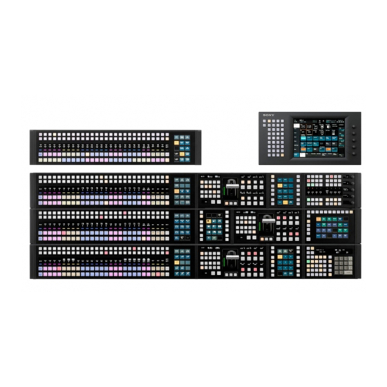
Integrated control panel
Hide thumbs Also See for ICP-X7000:
Table of Contents

Advertisement

INTEGRATED CONTROL PANEL
ICP-X7000
MKS-X7011
MKS-X7017
MKS-X7018
MKS-X7019
MKS-X7020
MKS-X7021
MKS-X7023
MKS-X7024
MKS-X7026
MKS-X7031TB
MKS-X7032
MKS-X7033
MKS-X7035
MKS-X7075
INSTALLATION MANUAL
1st Edition (Revised 7)
MKS-X2700
MKS-X7700
MKS-X7701
MKS-X7702
MKS-X7040
MKS-X7041
MKS-X7042
PWS-100SC1
PWS-110SC1
BZPS-7020
BZPS-7021
BZPS-7030
BZPS-7031
BZPS-7700

Advertisement

Table of Contents
loading

Summary of Contents for Sony ICP-X7000

  • Page 1 INTEGRATED CONTROL PANEL ICP-X7000 MKS-X7011 MKS-X2700 MKS-X7017 MKS-X7700 MKS-X7018 MKS-X7701 MKS-X7019 MKS-X7702 MKS-X7020 MKS-X7040 MKS-X7021 MKS-X7041 MKS-X7023 MKS-X7042 MKS-X7024 PWS-100SC1 MKS-X7026 PWS-110SC1 MKS-X7031TB BZPS-7020 MKS-X7032 BZPS-7021 MKS-X7033 BZPS-7030 MKS-X7035 BZPS-7031 MKS-X7075 BZPS-7700 INSTALLATION MANUAL 1st Edition (Revised 7)
  • Page 2 Conditions of Use: (1) Please use this information only for the purpose of sales, installation, configuration, and use of Sony products. Using this information for any purpose other than the purpose described foregoing is forbidden. (2) Do not copy, replicate, reproduce, alter, translate, transmit, sell, lease, or distribute this information in whole or in part without the prior written permission of the author.
  • Page 3 ICP-X7000 (SY) ICP-X7000 (CN) For MKS-X2700/MKS-X7700/PWS-100SC1/PWS- 110SC1 MKS-X7011 (SY) Serial No. 10001 and Higher Attention-when the product is installed in Rack: MKS-X7017 (SY) Serial No. 10001 and Higher MKS-X7018 (SY) Serial No. 10001 and Higher 1. Prevention against overloading of branch circuit MKS-X7019 (SY) Serial No.
  • Page 4 . Leave a space around the unit for ventilation. Follow the instructions for the above ports. . When the unit is installed on the desk or the like, keep the following space for service operation. For ICP-X7000/MKS-X7011/MKS-X7075/PWS- MKS-X2700 100SC1/PWS-110SC1 Right, Left: 4 cm or more...
  • Page 5: Table Of Contents

    PWS-100SC1 Installing Information ......2-7 (E) 1-13-5. MKS-X7011 ...........1-35 (E) 2-3-1. Operating Environment and Installation 1-13-6. ICP-X7000, MKS-X7075 ......1-35 (E) Space ..............2-7 (E) 1-14. Description of On-board Switches and LEDs ..1-36 (E) 2-3-2. Power Supply ...........2-9 (E) 1-14-1. MKS-X2700/MKS-X7700 ......1-36 (E) 2-3-3.
  • Page 6 Settings of Onboard Switch ......2-24 (E) 3. Service Overview 3-1. Troubleshooting............3-1 (E) 3-1-1. MKS-X2700, MKS-X7700 ......3-1 (E) 3-1-2. MKS-X7011 .............3-1 (E) 3-1-3. ICP-X7000, MKS-X7075 ........3-2 (E) 3-2. About the Data Backup Capacitor ......3-2 (E) 3-3. To Use Indicators Long ..........3-3 (E) 2 (E) ICP-X7000...
  • Page 7: Manual Structure

    Manual Structure Purpose of this manual This manual is the installation manual of Integrated Control Panel Pack ICP-X7000 and the optional units, MKS-X2700 and MKS-X7700 and optional units, and Switcher Control Station PWS-100SC1/PWS-110SC1. This manual is intended for use by trained system and service engineers, and de- scribes the information on installing the ICP-X7000.
  • Page 8: Contents

    Section 2 Installing the Options This section describes the installation of option. Section 3 Service Overview This section describes the troubleshooting and periodic inspection and maintenance. 4 (E) ICP-X7000...
  • Page 9: Installation

    Maximum 0.2 A MKS-X7011: Maximum 0.3 A Inrush current: ICP-X7000 (per row): 70 A (at peak), 10 A r.m.s. (AC 240 V) MKS-X7075: 70 A (at peak), 10 A r.m.s. (AC 240 V) MKS-X7011: 70 A (at peak), 10 A r.m.s. (AC240 V)
  • Page 10: Recommended Power Cord

    (For AC adaptor) This unit does not come with a power cord. To get a power cord, please contact your local Sony Sales For customers in the U.S.A. and Canada 1 Power cord, 125 V 7 A (2.0 m) : 1-846-101-21 Office/Service Center.
  • Page 11: Installation Space

    1-3. Installation Space 1-3-1. External Dimensions Main panel/AUX panel /Menu panel * A configuration using MKS-X7017/X7018/X7019 independently is called “AUX panel” in this manual. 584.8 Unit: mm 1-3 (E) ICP-X7000...
  • Page 12 Main panel (COMPACT, triple-row) 846.7 72.6 701.5 72.6 806.7 Unit: mm 1-4 (E) ICP-X7000...
  • Page 13 Menu panel (MKS-X7011) detailed dimensions 6-M3 Unit: mm 1-5 (E) ICP-X7000...
  • Page 14 Extension adaptor (MKS-X7075) Unit: mm 1-6 (E) ICP-X7000...
  • Page 15 System interface unit (MKS-X2700) Unit: mm 1-7 (E) ICP-X7000...
  • Page 16 System interface unit (MKS-X7700) Unit: mm 1-8 (E) ICP-X7000...
  • Page 17: Installation Space

    STANDARD: A panel consisting of a module (row: XPT, width: 137 mm), a module (row: XPT, width: 210.5 mm), and a module (row: XPT, width: 284 mm) . With respect to curve-shaped installation method, contact your local Sony Sales Office/Service Center. Main panel single-row type...
  • Page 18 Main panel size and combination of modules example (Module Size: 137mm/210.5mm/284mm) STANDARD NARROW COMPACT 1-10 (E) ICP-X7000...
  • Page 19 62.3 (rear side) ”Hole” 8-M4 67.2 (front side) Support plates TYPE COMPACT 20XPT 36XPT 1284 NARROW 28XPT 1130 20XPT 36XPT 1504 STANDARD 28XPT 1349 Unit: mm *1: The COMPACT type does not require the support plates. 20XPT 1195 1-11 (E) ICP-X7000...
  • Page 20 536.9 36XPT 845.7 1505 STANDARD 28XPT 691.3 1351 20XPT 536.9 1196 Unit: mm SHORT SIZE: A panel consisting of only MKS-X7017/X7018/X7019 FULL SIZE: A panel consisting of a combination of MKS-X7017/X7018/X7019 and the following model MKS-X7020/X7021/X7023/X7024/X7026/X7031TB/X7032/X7033/X7035, etc. 1-12 (E) ICP-X7000...
  • Page 21: Detailed Dimensions

    Product dimensions (allowance: ±1) (Refer to the table below.) 16.5 TYPE Product dimensions COMPACT 20XPT 36XPT 785.1 1174 1303 NARROW 28XPT 630.7 1019 1148 20XPT 476.3 864.6 36XPT 785.1 1393 1522 STANDARD 28XPT 630.7 1239 1368 20XPT 476.3 1085 1214 Unit: mm 1-13 (E) ICP-X7000...
  • Page 22 Main panel (Divisionally configuration) 71.2 22.3 62.3 71.2 22.3 62.3 71.2 22.3 62.3 67.2 11.5 67.2 11.5 67.2 11.5 76.2 16.6 76.2 16.6 76.2 16.6 1-14 (E) ICP-X7000...
  • Page 23 NARROW 28XPT 1148 20XPT 36XPT 1522 STANDARD 28XPT 1368 20XPT 1214 Unit: mm SHORT SIZE: A panel consisting of only MKS-X7017/X7018/X7019 FULL SIZE: A panel consisting of a combination of MKS-X7017/X7018/X7019 and the following model MKS-X7020/X7021/X7023/X7024/X7026/X7031TB/X7032/X7033/X7035, etc. 1-15 (E) ICP-X7000...
  • Page 24 Extension adaptor (MKS-X7075) 22.6 10 slotted hole 225 (Outside length of case) 16.6 245.5 0.5 262 0.6 (When side cap is used) (When supplied panel cover is used) Unit: mm 1-16 (E) ICP-X7000...
  • Page 25: Installing The Main Panel

    For ME separate types (2ME to 4ME separate types or Caps (L) 1ME to 3ME AUX BUS separate types) . Screw (B5 x 8): 4 pcs (per column) PSW3 . M5 washer (Sony part number: 7-688-005-11): 4 pcs (per Caps (R) column) 1-17 (E) ICP-X7000...
  • Page 26: Installing The Aux Panel

    Main panel Prepare the following screws and washers. . Screw (B5 x 8): 4 screws . M5 washer (Sony part number: 7-688-005-11): 4 washers 1. Detach the panel cover (L) and the panel cover (R) of the AUX panel. 2. Lift the AUX panel with two or more persons, and then place it on the adjustment console.
  • Page 27: Installing The Extension Adaptor

    Prepare the following screws and washers. . Screw (B5 x 8): 4 pcs PSW3 . M5 washer (Sony part number: 7-688-005-11): 4 pcs 1. Remove the right and left module covers. 2. Remove the four screws (PSW3 x 6) to detach the cap Cap (R) (L) and cap (R).
  • Page 28 4. Install the extension adaptor. (Refer to steps 3 to 6 in this section.) 5. Connect the AC adaptor and LAN cable, and clamp them with two clampers, after installing the extension adaptor. (Refer to step 6 of Section 1-4 ) 1-20 (E) ICP-X7000...
  • Page 29: Removing And Installing Cap/Diffusion Plate

    Cap pull tool, the tip of the Cap pull tool does not reach 3. Install the removed parts by reversing the steps of the groove of the diffusion plate and the cap/diffusion plate removal. may not be pulled out. Cap pull tool Groove Cap/diffusion plate Groove 1-21 (E) ICP-X7000...
  • Page 30: Removing And Installing Cap/Diffusion Plate Of Switch With Switch Guard

    4. Push switch cover until a snap is heard. Switch cover Hook Cap pull tool Projections Hook Cap pull tool Groove Switch guard Cap/diffusion plate Projection 1-22 (E) ICP-X7000...
  • Page 31 Cross-section view The switch cover must be in contact with the flange of the switch. Flange Flange Hook Arrow view Arrow view Switch cover Flange The switch cover must be in contact with the flange of the switch. 1-23 (E) ICP-X7000...
  • Page 32 Carefully insert the projections at the end of the cap pull tool into the grooves of the switch cover so as not to damage the switch cover and the panel by the pro- jections. Cap pull tool Groove Switch cover Projection 1-24 (E) ICP-X7000...
  • Page 33: Replacing Switch Label

    Replace the switch label according to the system configu- The menu panel (MKS-X7011) can be installed to the ration in combination with ICP-X7000 and setup settings. monitor arm (mounting dimensions below) conforming to Contact your local Sony Sales Office/Service Center about the VESA standard by using the adaptor supplied with ICP- label types and other information.
  • Page 34: Rack Mounting

    . Mount in the rack in a stable position. If several units are mounted in a rack, it is recommended that a ventilation fan is installed to prevent temperature rise 75 mm inside the rack. 100 mm Monitor arm 1-26 (E) ICP-X7000...
  • Page 35 1. Sufficiently loosen the four screws (with stopper) to detach the four feet. MKS-X2700 Rack tool MKS-X7700 Rack tool Feet Feet Screws (with stopper) Screws (with stopper) MKS-X7700 Rack tool Feet Feet Screws Screws (with stopper) (with stopper) 1-27 (E) ICP-X7000...
  • Page 36 Minimum depth of adaptor: 595 mm 4. Attach the right and left adaptors to the rack complete- ly using the specified six screws. (The illustration below shows the left adaptor.) Adaptor Rack 31.75 Rack Adaptor 31.75 MKS-X7700: 4U MKS-X2700: 1U Unit: mm 1-28 (E) ICP-X7000...
  • Page 37 (3) Disconnect the harness from the connector on the MKS-X7700 CA-90 board, and then detach the front panel. MKS-X7700 Clamper Connector Harness Screws (with stopper) CA-90 board Front panel Screws (with stopper) 9. Attach the front panel to the equipment. 1-29 (E) ICP-X7000...
  • Page 38: Matching Connectors And Cables

    Junction Shell 9-pin MKS-X7011 RJ-45 modular jack CAT5e or equivalent DEVICE USB Type A receptacle ICP-X7000 RJ-45 modular jack CAT5e or equivalent MKS-X7075 *1: Conforms to IEEE 802.3 Ethernet 1000BASE-TX standard. *2: Shield type is recommended. *3: Compliance with PoE + (IEEE802.3at) *4: Compliance with USB2.0...
  • Page 39: Input/Output Signals Of Connectors

    <Relay> ( 1) GPI OUT Signal Name Function GPI OUT : 1-36 TALLY/GPI TALLY/GPI OUT 1-18 OUT 19-36 OUT_1A OUT_19A General-purpose relay output(A) OUT_2A OUT_20A OUT_3A OUT_21A OUT_4A OUT_22A OUT_5A OUT_23A OUT_6A OUT_24A OUT_7A OUT_25A OUT_8A OUT_26A 1-31 (E) ICP-X7000...
  • Page 40: Mks-X7700

    Frame ground *1: This pin can be used as a +12 V input pin by setting the switch S1601 on the CA-90 board to ON. (Refer to “CA-90 board” in “1-14. Description of On-board Switches and LEDs”.) 1-32 (E) ICP-X7000...
  • Page 41: Mks-X7701

    *1: This pin can be used as a +12 V input pin by setting the switch S1601 on OUT_14A OUT_32A OUT_50A the CA-90 board to ON. (Refer to “CA-90 board” in “1-14. Description of On-board Switches and LEDs”.) 1-33 (E) ICP-X7000...
  • Page 42 GPI OUT : 1-54 . GPI input pins are pulled up on the board. These pins can be connected to 3.3 V TTL or open- collector output pins. 3.3 V 3.3 V 3.3 V GPI IN Buffer 1-34 (E) ICP-X7000...
  • Page 43: Mks-X7011

    1-13-5. MKS-X7011 1-13-6. ICP-X7000, MKS-X7075 1000BASE-T, PoE+, RJ-45 (8pin) 1000BASE-T, PoE+, RJ-45 (8pin) External View External View Pin No. Signal Name Function Pin No. Signal Name Function TRX1+ Transmitted/Received data (+) TRX1+ Transmitted/Received data (+) TRX1_ Transmitted/Received data (_) TRX1_...
  • Page 44: Description Of On-Board Switches And Leds

    Lit when the +1.0 V power is supplied. D409 (D-2): 2.5 V D403 (C-2): 1.0 V-2 +2.5 V power supply status indication. +1.0 V-2 power supply status indication. Lit when the +2.5 V power is supplied. Lit when the +1.0 V power is supplied. 1-36 (E) ICP-X7000...
  • Page 45 S3802 (D-1): SCU DBG SW Switch REF IN status indication. Used only for design. This LED is unlit while the REF signal is input to the REF IN connector, and is lit while the REF signal is not recognized. 1-37 (E) ICP-X7000...
  • Page 46 S2602 (C-1): NIOS8SB_RESET Switch Reset switch for the NIOS8SB(IC5). S3501 (C-1): SCU MON Switch The SIU CPU runs in the monitor mode when switch S502 is pressed while this switch is being pressed or when power is turned on. 1-38 (E) ICP-X7000...
  • Page 47 This switch is used to reset the IC1. D301* (K-1): CFG ERR (IC1: Serial IO FPGA) Pressing this switch initializes IC1. This LED indicates a configuration error of IC1. While this LED is lit red, IC1 may not be working cor- rectly. 1-39 (E) ICP-X7000...
  • Page 48 Lit when the +12 V power is supplied. If this LED does not light, the fuse may have blown. D212 (H-2): 3.3 V +3.3 V power supply status indication. Lit when the +3.3 V power is supplied. 1-40 (E) ICP-X7000...
  • Page 49 Lit when the +5 V -A power is supplied. D203 (H-1): 5 V-SBUS +5.0 V-SBUS power supply status indication. Lit when the +5.0 V-SBUS power is supplied. D204 (H-1): 3.3 V +3.3V power supply status indication. Lit when the +3.3 V power is supplied. 1-41 (E) ICP-X7000...
  • Page 50 Lit when the +5 V-A power is supplied. D203 (R-2): 5 V-SBUS +5.0 V-SBUS power supply status indication. Lit when the +5.0 V-SBUS power is supplied. D204 (R-2): 3.3 V +3.3V power supply status indication. Lit when the +3.3 V power is supplied. 1-42 (E) ICP-X7000...
  • Page 51 FP-250 board FP-250 board (Side A) <LED> D100 (C-1) to D124 (G-1): POWER Power supply status indication. This LED is lit when +5 V is supplied from CA-90 board correctly. 1-43 (E) ICP-X7000...
  • Page 52: Icp-X7000/Mks-X7075

    LE-402 board 1-14-2. ICP-X7000/MKS-X7075 PIF-53 board LE-402 board (Side B) <LED> D1: POWER Power supply unit status indication. This LED is lit green while +12 V is normally output and S403 the fans in the power supply unit are normally rotating.
  • Page 53 Lit when the +12 V power is supplied correctly. <Switch> S500 (C-1): RECONF Pressing this switch initializes KY-724 board. S301 (C-1): SETTING2 This switch is used for manufacturing at the factory. Do not change the setting of this switch. 1-45 (E) ICP-X7000...
  • Page 54 Lit when the +12 V power is supplied correctly. <Switch> S500 (F-1): RECONF Pressing this switch initializes KY-725 board. S301 (F-1): SETTING2 This switch is used for manufacturing at the factory. Do not change the setting of this switch. 1-46 (E) ICP-X7000...
  • Page 55 Lit when the +12 V power is supplied correctly. <Switch> S500 (G-1): RECONF Pressing this switch initializes KY-726 board. S301 (G-2): SETTING2 This switch is used for manufacturing at the factory. Do not change the setting of this switch. 1-47 (E) ICP-X7000...
  • Page 56 KY-727 board (MKS-X7024) D100 S500 KY-727 board (Side A) <LED> D100 (B-1): +12 V +12 V power supply status indication. Lit when the +12 V power is supplied correctly. <Switch> S500 (B-1): RECONF Pressing this switch initializes KY-727 board. 1-48 (E) ICP-X7000...
  • Page 57 KY-728 board (MKS-X7020) D100 S500 KY-728 board (Side A) <LED> D100 (B-2): +12 V +12 V power supply status indication. Lit when the +12 V power is supplied correctly. <Switch> S500 (B-2): RECONF Pressing this switch initializes KY-728 board. 1-49 (E) ICP-X7000...
  • Page 58 KY-729 board (MKS-X7033) S500 KY-729 board (Side A) <LED> D100 (E-3): +12 V +12 V power supply status indication. Lit when the +12 V power is supplied correctly. <Switch> S500 (E-2): RECONF Pressing this switch initializes KY-729 board. 1-50 (E) ICP-X7000...
  • Page 59 KY-731 board (MKS-X7031TB) S500 D100 KY-731 board (Side A) <LED> D100 (A-3): +12V +12 V power supply status indication. Lit when the +12 V power is supplied correctly. <Switch> S500 (B-4): RECONF Pressing this switch initializes KY-731 board. 1-51 (E) ICP-X7000...
  • Page 60 KY-732 board (MKS-X7035) S500 D100 KY-732 board (Side A) <LED> D100(E-2): +12 V +12 V power supply status indication. Lit when the +12 V power is supplied correctly. <Switch> S500 (E-1): RECONF Pressing this switch initializes KY-732 board. 1-52 (E) ICP-X7000...
  • Page 61 Lit when the +12 V power is supplied correctly. Lit when the +12 V power is supplied correctly. <Switch> <Switch> S500 (E-2): RECONF S500 (E-2): RECONF Pressing this switch initializes KY-755 board. Pressing this switch initializes KY-757 board. 1-53 (E) ICP-X7000...
  • Page 62: Mks-X7011

    Factory setting: All OFF Do not change this factory setting. S1803 (B-5): RECONF This switch is used to forcibly reboot the CA-91 board. S1901 (C-3): RESET This switch is used to reset the CPU hardware of CA-91 board. 1-54 (E) ICP-X7000...
  • Page 63 D1404 (G-1): 3.3V PLD +3.3 V power supply status indication. Lit when the +3.3 V power is supplied correctly. D1405 (G-1): 1.2V PLD +1.2 V power supply status indication. Lit when the +1.2 V power is supplied correctly. 1-55 (E) ICP-X7000...
  • Page 64 KY-723 board KY-723 board (Side A) <LED> D102 (E-1): 5 V +5 V power supply status indication. Lit when the +5 V power is supplied correctly. 1-56 (E) ICP-X7000...
  • Page 65: System Connection

    To AC adaptor To AC adaptor DC IN LAN DC IN LAN per row Integrated Control Panel Extension Adaptor To AC adaptor ICP-X7000 MKS-X7075 To AC adaptor *1: PC is only required when performing the “1-17. Maintenance Menu”. 1-57 (E) ICP-X7000...
  • Page 66: Example Of Connection To Xvs Series

    DC IN LAN per row Integrated Control Panel Extension Adaptor To AC adaptor ICP-X7000 MKS-X7075 To AC adaptor *1: PC is only required when performing the “1-17. Maintenance Menu”. *2: Required when using the Web Application of the XVS series.
  • Page 67: Example Of Connection To Ns-Bus

    . For details of remote controller connection using the NS-BUS and settings, see the MKS-R3210/R1620/R1630 installa- tion manual. . For connection to the NS-BUS, a network card for expansion is required. . For IP address settings related to A system and B system, refer to “1-17-4. Settings for External Protocol.” 1-59 (E) ICP-X7000...
  • Page 68: Example Of Connection To External Devices Through Amp Over Ip

    (AMP over IP) . Up to two system interface units (SIU1 and SIU2) can be connected to external devices. . Set the unit ID of SIU1 and SIU2 respectively according to “1-14. Description of On-board Switches and LEDs.” 1-60 (E) ICP-X7000...
  • Page 69: Example Of Connection Of Serial Tally Through A Network

    . Only two models (MKS-R3210 and MKS-R1620) of NS-BUS remote control panel can be used in this connection. . Up to 16 NS-BUS remote control panels per switcher control panel are connectable in this connection. (Example: Up to 64 NS-BUS remote control panels are connectable in a system including four switcher control panels.) 1-61 (E) ICP-X7000...
  • Page 70: Settings Of Pws-100Sc1/110Sc1

    The PWS-100SC1/PWS-110SC1 is provided with web server functions, and the setting menu can be displayed on the web browser of a PC or a tablet. The PWS-100SC1/PWS-110SC1 also enables settings and operation of the ICP-X7000. . Systems to be connected to MVS-8000X/7000X: The Maintenance menu allows you to make settings for the PWS-100SC1/PWS-110SC1 and the panel configuration (For details, refer to the section 1-17.).
  • Page 71 To make a connection to a URL (https:), perform the following procedure to install the root certificate corresponding to the server (Sony-IPLiveProduction-<serial number>) in the web browser. Also name resolution setting is required.
  • Page 72 “Sony-IPLiveProduction-<serial number>” (referred to in step 2) by registering the name resolution in the hosts file. 4. When accessing the URL of each menu after the name resolution has been set, access “https://Sony- IPLiveProduction-<serial number>” instead of “https://192.168.111.1”.
  • Page 73: Maintenance Menu

    Access the Root menu according to Section 1-16-1, and then click [Maintenance Menu] in [Links for applications]. 4. The authentication form is displayed. Enter the following user name and password, and then click [Log In]. User name: setup Password: sjx30260 1-65 (E) ICP-X7000...
  • Page 74: Panel Configuration

    The Maintenance Menu appears. 1-17-1. Panel Configuration The ICP-X7000 system can assign numbers to each panel row (including MKS-X7075) and set them for PWS-100SC1/PWS-110SC1. Be sure to set numbers in the following cases. . When starting a system for the first time: Be sure to set numbers for systems shipped before April 2016.
  • Page 75 Procedure 1. Open the Maintenance Menu and click [System Config] on the left side of the window. 2. The System Config window opens. Make setting on this window. Without this setting, noting is displayed under “1st Row.” 1-67 (E) ICP-X7000...
  • Page 76 (3) Select “1” in Group ID and click [Apply]. After [Apply] is clicked, the setting is applied. 4. Register devices in the unit. (1) On the System Config window, click [Configure] in the unit section to be set. 1-68 (E) ICP-X7000...
  • Page 77 After [Apply] is clicked, the setting is applied. It takes about 30 seconds to apply the setting because devices are rebooted at this time. Be sure to exit the Unit Config window by clicking [Apply] or [Cancel]. If page reloading is per- formed or the browser is directly closed, the setting may become unstable. 1-69 (E) ICP-X7000...
  • Page 78 (5) After the setting has been successfully completed, MAC addresses are shown in 1st Row, etc. The panel configuration procedure has been completed. 5. Set Time Zone. (1) Click [Time Setting] on the left side of the window. (2) The Time Setting window opens. 1-70 (E) ICP-X7000...
  • Page 79 6. After these settings have been completed, exit the web browser of the PC and restart the entire sys- tem. Aside from row numbers, M/E can be assigned for each row by selecting Engineering Setup > Panel > Config menu (7321) of MENU GUI. 1-71 (E) ICP-X7000...
  • Page 80: Pws-100Sc1/Pws-110Sc1 Network Settings

    . S1, S2 (SYSTEM LAN1, 2): This network is set when the network card is installed. When the network card is not installed, S1 and S2 are not displayed. Procedure 1. Open the Maintenance Menu and click [Network Setting] on the left side of the window. The Network Setting window is displayed. 1-72 (E) ICP-X7000...
  • Page 81 IP Address, Prefix Length, and Default Gateway columns respectively. When the “MANUAL” connection mode is selected, go to step (6). When the “OFF”, “AUTO” or “DHCP” connection mode is selected, go to step (9). 1-73 (E) ICP-X7000...
  • Page 82 DHCP server auto acquisition mode. Values acquired by the DHCP server are dis- played in the IP Address and Prefix Length columns respectively. When the “MANUAL” connection mode is selected, go to step (2). When the “OFF” or “DHCP” connection mode is selected, go to step (4). 1-74 (E) ICP-X7000...
  • Page 83: Network Settings For Connected Devices

    Set the IP address when making PWS-100SC1/PWS-110SC1 (SCS) redundant or connecting the system interface unit (SIU). Procedure 1. Open the Maintenance Menu and click [Other Network] on the left side of the window. The Other Network Setting window is displayed. 1-75 (E) ICP-X7000...
  • Page 84 (1) Enter a value (0 to 255) divided into four by periods in [IPv4 Address] of [SIU1 Util LAN] or [SIU2 Util LAN] as the IP address of respective IPv4. (2) Enter a value (8 to 30) in [Prefix Length] as the prefix length of respective IPv4. 4. Click [Apply]. The settings are stored. 1-76 (E) ICP-X7000...
  • Page 85: Settings For External Protocol

    (2) Enter a value (0 to 255) divided into four by periods in [IPv4 Address] as the IP address of IPv4 of a device to be connected by the NS-Bus ExternalControl protocol. (3) Enter a port number (0 to 65535) in [Port]. 1-77 (E) ICP-X7000...
  • Page 86: Settings When Using Network Aux Remote

    PC and to make network settings using the Web menu on the NS-BUS remote control panel. For details of the Web menu on the NS-BUS remote control panel, refer to the MKS-R3210/MKS-R1620 instruction manual. Preparation 1. Connect the LAN1 connector on the MKS-R3210/MKS-R1620 to the PC. 1-78 (E) ICP-X7000...
  • Page 87 Default gateway of NS-BUS remote control panel (MKS-R3210/MKS-R1620) . System Controller: IP address of switcher control station (PWS-100SC1/PWS-110SC1) . NTP Server: IP address of switcher control station (PWS-100SC1/PWS-110SC1) 3. Click the [Apply] button. 4. Restart the MKS-R3210/MKS-R1620. After restart, the set values are applied. 1-79 (E) ICP-X7000...
  • Page 88 2. Click [Network Setting] on the left side of the Maintenance Menu window. The Network Setting window appears. 3. Select the [Enable] radio button of “NTP Access for AUX Remote.” 4. Click the [Apply] button. The access permission setting is stored. 1-80 (E) ICP-X7000...
  • Page 89 4. Select the checkbox of NS-BUS remote control panel you want to associate from the AUX Remote Panel field. 5. Select the switcher control panel (PNL1 to PNL4) you want to associate from the [Move to] drop- down list. 6. Click the [Execute] button. The setting is executed. 1-81 (E) ICP-X7000...
  • Page 90 1. Select the [Delete] radio button of “Mode” on the AUX Remote Panel Config window. 2. Select the checkbox of NS-BUS remote control panel to be deleted from the AUX Remote Panel field. 3. Click the [Execute] button. The setting is executed. 1-82 (E) ICP-X7000...
  • Page 91: Setting Up Virtual Shot Box/Virtual Menu

    A license key that activates software license must be entered to use the virtual shot box or the virtual menu. Perform the following procedure to activate software license. Preparation 1. Access “Menu Setup”. (Refer to Section 1-16-1.) The Menu Setup login page opens. 1-83 (E) ICP-X7000...
  • Page 92 A dialog box to activate software license appears. 3. Enter the license key in [Input License Key] and tap [Activate]. For how to obtain the license key, contact your local Sony Sales Office/Service Center. A model-specific ID may be required to obtain the license key Model-specific IDs are shown in [Device Unique ID] of the License menu.
  • Page 93: Creating User Account

    This window shows that the BZPS-7020 license has been activated. Select a license and tap [Deactivate] to deactivate the selected software license. 1-18-2. Creating User Account Preparation 1. Access “Menu Setup”. (Refer to Section 1-16-1.) The Menu Setup login page opens. 1-85 (E) ICP-X7000...
  • Page 94 The following user name and password were set in the factory default setting. User name: admin Password: None Procedure 1. Tap [User Account] on the left of the window. The User Account menu appears. 2. Tap [Add]. A dialog box to add an account appears. 1-86 (E) ICP-X7000...
  • Page 95: Setting Up Automation Interface Software

    Entering a license key is required to enable the following software license. BZPS-7700: AUTOMATION INTERFACE SOFTWARE For the procedure to enable this software, refer to “1-18-1. Activating Software License.” For how to connect an external automation device, please contact your local Sony Sales Office/Service Center. 1-87 (E)
  • Page 96: Using Web Applications

    This menu can back up and restore switcher settings and resource share settings and import frame memory images to the switcher. Entering the following URL enables direct access. _ For using encrypted communication: https://(IP address of LAN 2)/xwm/file-manager _ For using unencrypted communication: http://(IP address of LAN 2)/xwm/file-manager 1-88 (E) ICP-X7000...
  • Page 97: Installation Of Options

    10-Key Pad Module Pull-bar . MKS-X7031TB Track Ball Module . MKS-X7032 Key Fader Module . MKS-X7033 Utility/Shotbox Module . MKS-X7035 Key Control Module . MKS-X7040 Blank Panel (1/3) . MKS-X7041 Blank Panel (1/2) . MKS-X7042 Blank Panel (1/6) 2-1 (E) ICP-X7000...
  • Page 98 MKS-X7031TB, refer to “Installing the trackball” described later.) 4. Disconnect the fine-wire coaxial cable from the operation module to be replaced, and then remove the operation module. Module covers Screws (with stopper) Connector Operation module Screws (with stopper) Fine-wire coaxial cable 2-2 (E) ICP-X7000...
  • Page 99 . When a blank panel is installed, connect the modules on the right side of the blank panel without providing a space. PIF-53 board Cable Clamp Fine-wire coaxial cable Clamper Clampers PIF-53 board CN1100 Lead (red) CN1101 CN1102 CN1103 Fine-wire coaxial cable 2-3 (E) ICP-X7000...
  • Page 100 Operation module (with stopper) (MKS-X7031TB) Connector Operation module Screws (with stopper) 11. Install the trackball and the ball holder. 12. Turn the ball holder clockwise (2) until it locks. Ball holder Trackball Fine-wire coaxial cable Operation module (MKS-X7031TB) 2-4 (E) ICP-X7000...
  • Page 101 4. Attach the panel cover (L) and the panel cover (R). Module cover Panel cover (L) Module cover Screws Operation module (with stopper) Panel cover (R) Operation module Screws (with stopper) Screws Fine-wire (with stopper) coaxial cable Screws (with stopper) Extension adaptor Cable Clamp PIF-53 board CN1100 2-5 (E) ICP-X7000...
  • Page 102: Installing The Connector Board (Mks-X7700)

    Be sure to install an optional board or a blank panel in each slot on the rear panel. Screws (with stopper) Fine-wire coaxial cable Cable Clamp PIF-53 board CN1100 Cable PIF-53 board CN1100 Clamp Fine-wire coaxial cable 2-6 (E) ICP-X7000...
  • Page 103: Pws-100Sc1 Installing Information

    Do not incline the unit from front to back at an angle of 30 degrees or more. Unless you use the unit on horizontal plane, secure it so that it will not slip down. Connector board Tighten screws 2-7 (E) ICP-X7000...
  • Page 104: Space

    4 centimeters of space in the left and right sides. Leaving 40 centimeters or more of space above the unit is in temperature. recommended for service operation. Mass of this unit (not including option) : approx. 14 kg 43.6 633.8 152.5 115.5 115.5 Unit : mm 2-8 (E) ICP-X7000...
  • Page 105: Power Supply

    15.875 mm Rack unit This unit does not come with a power cord. 44.45 mm 15.875 mm To get a power cord, please contact your local Sony Sales Inside dimension Office/Service Center. 450 mm min. Mounting dimension 465 mm ±1.6 .
  • Page 106 (up, rear, right, and left) at the rear of the unit so as not to block airflow. (Refer to Fig. 2) . Adjust the temperature inside the rack within the range of the unit’s operating temperature. (Refer to Section 2-3-1) 2-10 (E) ICP-X7000...
  • Page 107 The following part is necessary to mount the unit to the square-hole rack. Rack mount parts assembly (A-2126-310-A) Components of rack mount parts assembly . Positioning plate............4 pcs . Plate nut (M5) ............2 pcs Positioning plate Plate nut (M5) 2-11 (E) ICP-X7000...
  • Page 108 (The following figure shows the left adaptor.) Front Plate nut (M5) Positioning plate Release paper 31.75 Adaptor Rear Viewed from inside the rack angle Plate nut (M5) Positioning plate Positioning plate Adaptor 31.75 Bosses Holes Square Plate nut (M5) Bosses Holes Unit: mm 2-12 (E) ICP-X7000...
  • Page 109 7. Secure the rack angles to the rack with the specified four screws (B5 x 12). Use the screws (B5 x 12) supplied with the unit. Anti-drop screw Front panel Anti-drop screw 2-13 (E) ICP-X7000...
  • Page 110: Connector Input/Output Signals

    RJ-45 8-pin (2) 1000BASE-T, 100BASE-TX HDMI Type A (1) HDMI Ver. 1.4a, 1920 x 1200 maximum resolution, 60 Hz DisplayPort DisplayPort (1) Not used Remote 1/2, 3/4, 5 RJ-45 (3) Not used SYSTEM TC BNC (1) Not used 2-14 (E) ICP-X7000...
  • Page 111: Connectors And Cables

    2-3-5. Connectors and Cables Use the following connectors (or cables) or equivalents for cable connection. Panel Indication Applicable Connector (Cable) Sony Part No. Remarks HDMI HDMI type A Use the cable that meets any of the following specifications. High Speed HDMI Cable, Premium High Speed HDMI Cable Use a cable for super speed USB.
  • Page 112: Pws-110Sc1 Installing Information

    Maximum inclination angle: 30 degrees Do not incline the unit from front to back at an angle of 30 degrees or more. Unless you use the unit on horizontal plane, secure it so that it will not slip down. 2-16 (E) ICP-X7000...
  • Page 113: Space

    4 centimeters of space in the left and right sides. Leaving 40 centimeters or more of space above the unit is in temperature. recommended for service operation. Mass of this unit (not including option) : approx. 10.4 kg 43.6 162.5 115.5 115.5 Unit : mm 2-17 (E) ICP-X7000...
  • Page 114: Power Supply

    15.875 mm Rack unit This unit does not come with a power cord. 44.45 mm 15.875 mm To get a power cord, please contact your local Sony Sales Inside dimension Office/Service Center. 450 mm min. Mounting dimension 465 mm ±1.6 .
  • Page 115 (up, rear, right, and left) at the rear of the unit so as not to block airflow. (Refer to Fig. 2) . Adjust the temperature inside the rack within the range of the unit’s operating temperature. (Refer to Section 2-4-1) 2-19 (E) ICP-X7000...
  • Page 116 The following part is necessary to mount the unit to the square-hole rack. Rack mount parts assembly (A-2126-310-A) Components of rack mount parts assembly . Positioning plate............4 pcs . Plate nut (M5) ............2 pcs Positioning plate Plate nut (M5) 2-20 (E) ICP-X7000...
  • Page 117 (The following figure shows the left adaptor.) Front Plate nut (M5) Positioning plate Release paper 31.75 Adaptor Rear Viewed from inside the rack angle Plate nut (M5) Positioning plate Positioning plate Adaptor 31.75 Bosses Holes Square Plate nut (M5) Bosses Holes Unit: mm 2-21 (E) ICP-X7000...
  • Page 118 7. Secure the rack angles to the rack with the specified four screws (B5 x 12). Use the screws (B5 x 12) supplied with the unit. Anti-drop screw Front panel Anti-drop screw 2-22 (E) ICP-X7000...
  • Page 119: Connector Input/Output Signals

    RJ-45 8-pin (2) 1000BASE-T, 100BASE-TX HDMI Type A (1) HDMI Ver. 1.4a, 1920 x 1200 maximum resolution, 60 Hz DisplayPort DisplayPort (1) Not used Remote 1/2, 3/4, 5 RJ-45 (3) Not used SYSTEM TC BNC (1) Not used 2-23 (E) ICP-X7000...
  • Page 120: Connectors And Cables

    2-4-5. Connectors and Cables Use the following connectors (or cables) or equivalents for cable connection. Panel Indication Applicable Connector (Cable) Sony Part No. Remarks HDMI HDMI type A Use the cable that meets any of the following specifications. High Speed HDMI Cable, Premium High Speed HDMI Cable Use a cable for super speed USB.
  • Page 121: Service Overview

    Is the power cord of the is used) MKS-X2700/X7700 Connect it correctly. connected correctly? Is the left side switches on The MKS-X7011 is probably the MKS-X7011 lit? defective. The power supply unit is probably defective. LCD of the MKS-X7011 is probably defective. 3-1 (E) ICP-X7000...
  • Page 122: Icp-X7000, Mks-X7075

    3-1-3. ICP-X7000, MKS-X7075 The menu does not start correctly. LEDs and other indicators do not light. Flow 3 “Recovery dialog” appears on the menu screen. Flow 4 LEDs and other indicators do not light. Check the PoE HUB status. Is PoE HUB working...
  • Page 123: To Use Indicators Long

    3-3. To Use Indicators Long In the ICP-X7000, RGB LEDs are used for lighting switch- es and organic EL display devices are used for source name indicators. The brightness of these devices gradually decreases and burn-in of display patterns is generated in proportion to the operating time or the brightness of these devices.
  • Page 126 ICP-X7000 (SY) Printed in Japan Sony Corporation ICP-X7000 (CN) J, E 2018. 11 08 9-932-666-01 ©2014...

Table of Contents