
Related Manuals for Advantech EKI-9316P Series


Summary of Contents for Advantech EKI-9316P Series
- Page 1 EKI-9316P/ EKI-9312P User Manual Series Industrial Managed 16-Port and 12- Port Full Gigabit Switch with PoE/ PoE+...
-
Page 2: Table Of Contents
Content Chapter 1 Hardware Installation 1.1. Introduction ..........2 1.2. - Page 3 1.10.5 Serial Console Port Wiring............29 1.10.6 USB Console Port Wiring............29 1.11. Reset Button ..........30 Chapter 2 First Time Setup 2.1.
- Page 4 3.3.16 TACACS+ ................101 3.3.17 RADIUS ................. 103 3.3.18 ARP Table ................112 3.3.19 Reset Button ................112 3.3.20 Login Sessions ..............113 3.4. Switching ..........114 3.4.1 MAC Address Table...............
- Page 5 3.8. Maintenance ......... . . 263 3.8.1 System Resources..............
-
Page 6: Federal Communication Commission Interference Statement
We recommend the use of shielded cables. This kind of cable is available from Advantech. Please contact your local supplier for ordering information. This product has passed the CE test for environmental specifications. Test conditions for passing included the equipment being operated within an industrial enclosure. - Page 7 Because of Advantech’s high quality-control standards and rigorous testing, most of our customers never need to use our repair service. If an Advantech product is defective, it will be repaired or replaced at no charge during the warranty period. For out of-warranty repairs, you will be billed according to the cost of replacement materials, service time and freight.
- Page 8 Note signs are used to provide additional information for the device or settings. Copyright Copyright © 2014 Advantech Inc. All rights reserved. No part of this publication may be reproduced, adapted, stored in a retrieval system, translated into any language, or transmit-ted...
-
Page 9: Customer Support
Customer Support Safety Information Safety Requirements Before you begin installing the device, read through the following safety guidelines to prevent personal injury or property damage. Seek assistance from a trained professional installer, especially if it is your first time to install this device. - Page 10 Electrostatic Discharge Requirements Follow the steps below to protect components from electrostatic discharge: 1. Wear an ESD wrist strap when installing the device. 2. Handle the power adapter by its edge and do not touch any component or printed circuit boards. Temperature/Humidity Requirements Make sure to keep the temperature and humidity of the installation location at an optimal level.
- Page 11 Power over Ethernet (PoE) PoE Requirements This product was in-door used and not connected to outside plant. The equipment is to be connected only to PoE networks without routing to the outside plant. Warnings Do NOT place your device near water such as a wet basement. ...
-
Page 12: About This Manual
About This Manual This user manual is intended to guide professional installers in installing and configuring the EKI-9316P/ EKI-9312P (PoE/PoE+) and EKI-9316 / EKI-9312 Industrial Managed 16- Port and 12-Port Full Gigabit Switches series, and in building the infrastructure centered on it. - Page 13 Hardware Installation Chapter 1...
-
Page 14: Introduction
ARDWARE NSTALLATION 1.1. Introduction The EKI-9316P/EKI-9312P series include EKI-9316P, EKI-9312P, EKI-9316 and EKI-9312. 1.2. Key Features 1.2.1 EKI-9316P/ EKI-9312P -40°C to 75°C operating temperature range IEEE802.3at PoE+ to supply 30W power IEEE802.3af PoE to supply 15.4W power ... -
Page 15: Product Models
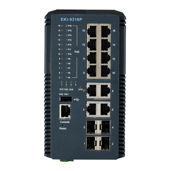
ARDWARE NSTALLATION 1.3. Product Models 1.3.1 EKI-9316P/ EKI-9312P EKI-9316P EKI-9312P EKI-7756FHPI EKI-9312P SYS R.M. ALM SYS R.M. ALM PW2 PW1 PW2 PW1 Console Console Reset Reset Figure 1-1. EKI-9316P/ EKI-9312P 1.3.2 EKI-9316 / EKI-9312 EKI-9316 EKI-9312 EKI-9316 EKI-9312 1 2 3 SYS R.M. -
Page 16: Specifications
ARDWARE NSTALLATION 1.4. Specifications 1.4.1 EKI-9316P / EKI-9312P Table 1-1. EKI-9316P / EKI-9312P Specifications Specifications Description Interface I/O Port 8 x 10/100/1000Base-T/TX RJ-45 (P5~P12 with PoE/ PoE+) 12 x 10/100/1000Base-T/TX RJ-45 (P5~P16 with PoE/PoE+) 4 x 100/1000Base-FX/X SFP (P1~P4) Console port RJ-45 F/W backup port... - Page 17 ARDWARE NSTALLATION Table 1-1. EKI-9316P / EKI-9312P Specifications (Continued) Specifications Description Switch Properties MAC Address 16K entries Switching Band- EKI-9316P: 32Gbps width EKI-9312P: 24Gbps Packet Buffer 1.5MB Jumbo Frame 12KB Priority Queue Simultaneous VLAN VLAN ID Range 1~4093 Multicast Group 1024 Max.
- Page 18 ARDWARE NSTALLATION Table 1-1. EKI-9316P / EKI-9312P Specifications (Continued) Specifications Description Technology com- IEEE 802.1ab LLDP, 802.1ad provider bridging, 802.1d STP, pliance 802.1p Ethernet priority with user provisioning and map- ping, 802.1q Virtual LANs w/ port-based VLANs, 802.1s MSTP, 802.1w RSTP, 802.1x Authentication, 802.3 10BaseT, 802.3ab 1000BaseT(X), 802.3ac VLAN tag- ging, 802.3ad Link aggregation, 802.3af PoE, 802.3at PoE+, 802.3u 100BaseT(X), 802.3x Flow Control, 802.3z...
-
Page 19: Eki-9316 / Eki-9312
ARDWARE NSTALLATION Table 1-1. EKI-9316P / EKI-9312P Specifications (Continued) Specifications Description Certifications CE, FCC Class A UL60950 C1D2 EN61000-6-4; EN61000-6-2; EN61000-4-2 (ESD) Level 4 EN61000-4-3 (RS) Level 4; EN61000-4-4 (EFT) Level 4 EN61000-4-5 (Surge) Level 4; EN61000-4-6 (CS) ... - Page 20 ARDWARE NSTALLATION Table 1-2. EKI-9316 / EKI-9312 Specifications (Continued) Specifications Description Switch Properties MAC Address 16K entries Switching Band- EKI-9316: 32Gbps width EKI-9312: 24Gbps Packet Buffer 1.5MB Jumbo Frame 12KB Priority Queue Simultaneous VLAN VLAN ID Range 1~4093 Multicast Group 1024 Max.
- Page 21 ARDWARE NSTALLATION Table 1-2. EKI-9316 / EKI-9312 Specifications (Continued) Specifications Description Technology com- IEEE 802.1ab LLDP, 802.1ad provider bridging, 802.1d STP, pliance 802.1p Ethernet priority with user provisioning and map- ping, 802.1q Virtual LANs w/ port-based VLANs, 802.1s MSTP, 802.1w RSTP, 802.1x Authentication, 802.3 10BaseT, 802.3ab 1000BaseT(X), 802.3ac VLAN tag- ging, 802.3ad Link aggregation, 802.3u 100BaseT(X), 802.3x Flow Control, 802.3z 1000BaseX...
-
Page 22: Package Contents
ARDWARE NSTALLATION Table 1-2. EKI-9316 / EKI-9312 Specifications (Continued) Specifications Description Certifications CE, FCC Class A UL60950 C1D2 EN61000-6-4; EN61000-6-2; EN61000-4-2 (ESD) Level 4 EN61000-4-3 (RS) Level 4; EN61000-4-4 (EFT) Level 4 EN61000-4-5 (Surge) Level 4; EN61000-4-6 (CS) ... -
Page 23: Product Views
ARDWARE NSTALLATION 1.6. Product Views 1.6.1 Front View EKI-9316P SYS R.M. ALM PW2 PW1 Console Reset Figure 1-3. Front View Table 1-3. Front View Item Description PoE LED See Activity and PoE LED Panel on page 13 (EKI-9316P / EKI-9312Ponly) ETH port LED 10/100BaseT/TX LED indicator ETH port LED... - Page 24 ARDWARE NSTALLATION System LED Panel SYS R.M. ALM PW2 PW1 Figure 1-4. System LED Panel Table 1-4. System LED Panel LED Name LED Color Description ALM LED Solid red Defined major policies are detected Blinking red Defined minor policies are detected Powered off or system is operating normally CFG LED Solid amber...
- Page 25 ARDWARE NSTALLATION Activity and PoE LED Panel Figure 1-5. Activity and PoE LED Panel Table 1-5. Activity and PoE LED Panel LED Name LED Color Description Link / Status / Solid green Secure 1000Mbps connection (Only for Gigabit Ether- Speed net port) Blinking green Data transmission rate of 1000Mbps (Only for Gigabit...
-
Page 26: Rear View
ARDWARE NSTALLATION 1.6.2 Rear View Figure 1-6. Rear View Table 1-6. Rear View Item Description Wall mounting holes Screw holes (x4) used in the installation of a wall mounting plate DIN-Rail mounting Mounting plate used for the installation to a standard DIN rail plate... -
Page 27: Bottom View
ARDWARE NSTALLATION 1.6.3 Bottom View Figure 1-7. Bottom View Table 1-7. Bottom View Item Description Terminal block Connect cabling for power and alarm wiring Ground terminal Screw terminal used to ground chassis 1.7. Mounting Options 1.7.1 DIN Rail Mounting The DIN rail mount option is the quickest installation option. Additionally, it optimizes the use of rail space. - Page 28 ARDWARE NSTALLATION Installing the DIN-Rail Mounting Kit Insert the top back of the mounting bracket over the DIN rail. Push the bottom of the switch towards the DIN rail until it snaps into place. DIN Rail Figure 1-8. Installing the DIN-Rail Mounting Kit Removing the DIN-Rail Mounting Kit 1.
-
Page 29: Wall Mounting (Optional Kit By Request)
ARDWARE NSTALLATION 1.7.2 Wall Mounting (Optional Kit by Request) The wall mounting option provides better shock and vibration resistance than the DIN rail vertical mount. When installing, make sure to allow for enough space to properly install the cabling. Before the device can be mounted on a wall, you will need to remove the DIN rail plate. 1. - Page 30 ARDWARE NSTALLATION 10. Insert the screws into the wall sinks. Leave a 6mm gap between the wall and the screw head to allow for wall mount plate insertion. 6.0 mm 6.0 mm 3.5 mm Figure 1-11. Securing Wall Mounting Screws Make sure the screws dimensions are suitable for use with the wall mounting plate.
-
Page 31: Hardware Dimensions
ARDWARE NSTALLATION 1.8. Hardware Dimensions 155mm 155mm 6.1inch 6.1inch 10mm 0.39inch 86mm 125mm 3.39inch 4.92inch Figure 1-13. Hardware Dimensions 1.9. Power and Alarm Wiring 1.9.1 Overview OWER DOWN AND DISCONNECT THE POWER CORD BEFORE SERVICING OR WIRING THE SWITCH Do not disconnect modules or cabling unless the power is first switched off. The device only supports the voltage outlined in the type plate. -
Page 32: Considerations
ARDWARE NSTALLATION EKI-9316 / EKI-9312 supports 24 and 48 VDC and EKI-9316P / EKI-9312P supports 48 VDC (for PoE) and 50 VDC (for PoE+). For PoE sourcing (PSE) operation, a power range of 46 to 57 VDC is necessary. Make sure the 48 VDC supply is rated at 15.4W per PoE port and the 50 VDC supply is rated at 30W per PoE+ port. -
Page 33: Grounding The Device
ARDWARE NSTALLATION 1.9.3 Grounding the Device Do not disconnect modules or cabling unless the power is first switched off. The device only supports the voltage outlined in the type plate. Do not use any other power components except those specifically designated for the switch device. Before connecting the device properly ground the device. -
Page 34: Wiring A Relay Contact
ARDWARE NSTALLATION 1.9.4 Wiring a Relay Contact The following section details the wiring of the relay output. The terminal block on the EKI- 9316P / EKI-9312P is wired and then installed onto the terminal receptor located on the EKI-9316P / EKI-9312P. Figure 1-17. -
Page 35: Wiring The Power Inputs
ARDWARE NSTALLATION 1.9.5 Wiring the Power Inputs Do not disconnect modules or cabling unless the power is first switched off. The device only supports the voltage outlined in the type plate. Do not use any other power components except those specifically designated for the switch device. POWER DOWN AND DISCONNECT THE POWER CORD BEFORE SERVICING OR WIRING THE SWITCH. -
Page 36: Wiring The Digital Inputs
ARDWARE NSTALLATION 5. Tighten the wire-clamp screws to secure the DC wires in place. Loosening Wire-clamp Screws Securing Wire-clamp Screws Installing DC Wires Figure 1-20. Installing DC Wires in a Terminal Block 6. Align the terminal block over the terminal block receptor on the switch. 7. -
Page 37: Communication Port Wiring
The Gigabit Ethernet ports on the switch are 100/1000BaseSFP Fiber ports, which require using the 100M or 1G mini-GBIC fiber transceivers to work properly. Advantech provides completed transceiver models for different distance requirement. The concept behind the LC port and cable is quite straightforward. Suppose that you are connecting devices I and II;... - Page 38 ARDWARE NSTALLATION Remember to connect the Tx (transmit) port of device I to the Rx (receive) port of device II, and the Rx (receive) port of device I to the Tx (transmit) port of device II. If you make your own cable, we suggest labeling the two sides of the same line with the same letter (A-to-A and B-to-B, as shown below, or A1-to-A2 and B1-to-B2).
- Page 39 ARDWARE NSTALLATION 5. Make sure the module is seated correctly before sliding the module into the slot. A click sounds when it is locked in place. Handle Figure 1-24. Installing an SFP Transceiver If you are attaching fiber optic cables to the transceiver, continue with the following step.
-
Page 40: Network Device Validation
1.10.3 Network Device Validation Advantech industrial Ethernet switches support 10/100BaseT or 10/100/1000BaseT on the RJ45 (copper) ports and 100BaseFX or gigabit Ethernet on the fiber optic ports. Make sure the devices are connected to the corresponding ports for proper operation. -
Page 41: Serial Console Port Wiring
ARDWARE NSTALLATION 1.10.5 Serial Console Port Wiring The industrial switch supports a secondary means of management. By connecting the RJ45 to RS232 serial cable between a COM port on your PC (9-pin D-sub female) and the switch’s RJ45 (RJ45) port, a wired connection for management can be established. To terminal or PC To console port Figure 1-28. -
Page 42: Reset Button
ARDWARE NSTALLATION 1.11. Reset Button Reset configuration to factory default: Press and hold Reset button for 2 seconds. System reboot: Press and hold Reset button for 5 seconds. Do NOT power off the Ethernet switch when loading default settings. -
Page 43: First Time Setup
First Time Setup Chapter 2... -
Page 44: First Time Setup
IRST ETUP 2.1. First Time Setup 2.1.1 Overview The Industrial Ethernet Managed Switch is a configurable device that facilitates the interconnection of Ethernet devices on an Ethernet network. This includes computers, operator interfaces, I/O, controllers, RTUs, PLCs, other switches/hubs or any device that supports the standard IEEE 802.3 protocol. -
Page 45: Using The Graphical (Web) Interface
IRST ETUP 2.1.4 Using the Graphical (Web) Interface The graphical interface is provided via a web server in the switch and can be accessed via a web browser such as Opera, Mozilla, or Internet Explorer. JavaScript must be supported and enabled in your browser for the graphical inter- face to work correctly. -
Page 46: Configuring The Ethernet Ports
IRST ETUP NTP Server: The IP address or domain name of an NTP (Network Time Protocol) server from which the switch may retrieve the current time at startup. Please note that using a domain name requires that at least one domain name server be configured. ... -
Page 47: Web Browser Configuration
IRST ETUP 2.2. Web Browser Configuration The switch has an HTML based user interface embedded in the flash memory. The interface offers an easy to use means to manage basic and advanced switch functions. The interface allows for local or remote switch configuration anywhere on the network. The interface is designed for use with [Internet Explorer (6.0), Chrome, Firefox]. -
Page 48: Management Interface
Management Interface Chapter 3... -
Page 49: Log In
ANAGEMENT NTERFACE 3.1. Log In To access the log in window, connect the device to the network, see “Communication Port Wiring” on page 25 and open a browser window. Enter the default user name and password (admin/admin) to log into the management inter-face. -
Page 50: Management
ANAGEMENT NTERFACE 5. Click Submit to change the current account settings. Figure 3-2. Changing Default Password After saving all the desired settings, perform a system save (Maintenance > Config Save). The changes are saved and retained even after a reboot. 3.3. -
Page 51: System Description
ANAGEMENT NTERFACE The following table describes the items in the previous menu. Table 3-1. Management > System Information Item Description System Description Displays the product name of the switch. Machine Type Displays the machine type of the switch. Machine Model Displays the model name of the switch. -
Page 52: Ip Configuration
ANAGEMENT NTERFACE The following table describes the items in the previous menu. Table 3-2. Management > System Description Item Description System Description Displays the product name of the switch. System Name Enter the system name: up to 255 alphanumeric characters. The default is blank. System Location Enter the location: up to 255 alphanumeric characters. -
Page 53: Aaa
ANAGEMENT NTERFACE The following table describes the items in the previous menu. Table 3-3. Management > IP Configuration Item Description Interface Status Displays the link status. IPv4 Network Configura- Click the drop-down menu to specify a protocol after power-up. The default is tion Protocol None. - Page 54 ANAGEMENT NTERFACE The following table describes the items in the previous menu. Table 3-4. Management > AAA > Authentication Configuration Parameter Description Access Mode Click the drop-down menu to specify login list or enable list. The default is default- List for all newly created user. Click the drop-down menu to select the authentication list.
- Page 55 ANAGEMENT NTERFACE Authentication Status The Authentication Status page displays a summary of the Login Authentication List, Enable Authentication List, and Login and Enable Method Lists for Console, Telnet, and SSH. To access this page, click Management > AAA > Authentication Status. Figure 3-7.
- Page 56 ANAGEMENT NTERFACE Table 3-5. Management > AAA > Authentication Status (Continued) Parameter Description 1. Select the authentication profile to remove. Remove 2. Click Submit to remove the profile. Click Submit to update the screen. To save the values across a power cycle per- Submit form a system save.
- Page 57 ANAGEMENT NTERFACE The following table describes the items in the previous menu. Table 3-6. Management > AAA > Authentication Preference Parameter Description Click the drop-down menu to verify console users’ profiles. Console Login or Enable - Specify the login list and enable list which will be used to val- ...
- Page 58 ANAGEMENT NTERFACE Table 3-6. Management > AAA > Authentication Preference (Continued) Parameter Description Dot1x Click the drop-down menu to select an authentication method to verify the Dof1x access. Method - Click the drop-down menu to select a method. The method options ...
- Page 59 ANAGEMENT NTERFACE Table 3-7. Management > AAA > Accounting Configuration (Continued) Parameter Description Record Type Click the drop-down menu to select a record type. StartStop - Account when the start and end of an user session or executed commands. StopOnly - Account when the end of an user session or executed commands.
- Page 60 ANAGEMENT NTERFACE The following table describes the items in the previous menu. Table 3-8. Management > AAA > Accounting Status Parameter Description Accounting List Displays the all accounting profiles. Methods List Displays the accounting methods. Radius - RADIUS is used to account user exec sessions and user executed commands.
-
Page 61: Local Password Management
ANAGEMENT NTERFACE The following table describes the items in the previous menu. Table 3-9. Management > AAA > Accounting Preference Parameter Description Console Click the drop-down menu to specify the profile. Accounting profiles used to account console users activity. Exec or Commands - Specify the Exec list and Commands list which will be used to account for user activity associated with the list. - Page 62 ANAGEMENT NTERFACE The following table describes the items in the previous menu. Table 3-10. Management > Local Password Management > User Accounts Parameter Description User Click the drop-down menu to configure an existing account or to create a new one. Up to support five "Read-Only"...
-
Page 63: Line Password
ANAGEMENT NTERFACE Line Password The Line Password function allows you to configure the Telnet access password. Select the line mode type from the following screen before setting up the access password. To access this page, click Management > Local Password Management > Line Pass-word. -
Page 64: Power Over Ethernet
ANAGEMENT NTERFACE The following table describes the items in the previous menu. Table 3-12. Management > Local Password Management > Enable Password Parameter Description Enable Password (8- Enter the password (between 8 to 64 characters) for accessing the device via con- 64 characters) sole, telnet, or source telnet. - Page 65 ANAGEMENT NTERFACE The following table describes the items in the previous menu. Table 3-13. Management > Power over Ethernet > Global Configuration and Status Parameter Description Admin Mode Click the drop-down menu to enable or disable the admin mode. The default is Enable.
- Page 66 ANAGEMENT NTERFACE Figure 3-16. Management > Power over Ethernet > Interface Configuration and Status The following table describes the items in the previous menu. Table 3-14. Management > Power over Ethernet > Interface Configuration and Status Parameter Description Interface Click the drop-down menu to select a PSE port to apply the settings. Admin Mode Click the drop-down menu to enable or disable PSE function of the port.
- Page 67 ANAGEMENT NTERFACE Table 3-14. Management > Power over Ethernet > Interface Configuration and Status (Continued) Parameter Description Power Class Displays the PD power classify level. N/A - Specifies the PSE port is not delivering power. Class-0 - Specifies PSE port power class level-0 is selected. The maximal out- put power in PSE side is 30 Watts.
-
Page 68: Interface Statistics
ANAGEMENT NTERFACE Interface Statistics The Interface Statistics displays information for each interface. To access this page, click Management > Power over Ethernet > Interface Statistics. Figure 3-17. Management > Power over Ethernet > Interface Statistics The following table describes the items in the previous menu. Table 3-15. -
Page 69: Email Alerts
ANAGEMENT NTERFACE 3.3.7 Email Alerts Email Alert Global Configuration The Email Alert Global Configuration page allows users to configure email alert settings. To access this page, click Management > Email Alerts > Email Alert Global Configuration. Figure 3-18. Management > Email Alerts > Email Alert Global Configuration The following table describes the items in the previous menu. - Page 70 ANAGEMENT NTERFACE Table 3-16. Management > Email Alerts > Email Alert Global Configuration (Continued) Parameter Description Non Urgent Mes- Click the drop-down menu to select the severity level for non-urgent log messages. sages Severity The default is Warning. The level options are: Emergency - Indicates system is unusable.
-
Page 71: Email Alert Mail Server Configuration
ANAGEMENT NTERFACE Email Alert Mail Server Configuration The Email Alert Mail Server Configuration page allows users to configure mail server set-tings. To access this page, click Management > Email Alerts > Email Alert Mail Server Configuration. Figure 3-19. Management > Email Alerts > Email Alert Mail Server Configuration The following table describes the items in the previous menu. - Page 72 ANAGEMENT NTERFACE Email Alert Statistics The Email Alert Statistics displays a summary of the emails sent, received, and the time that has lapsed since the last email sent. To access this page, click Management > Email Alerts > Email Alert Mail Statistics. Figure 3-20.
-
Page 73: Email Alert To Address Configuration
ANAGEMENT NTERFACE The following table describes the items in the previous menu. Table 3-19. Management > Email Alerts > Email Alert Subject Configuration Parameter Description Message Type Click the drop-down menu to configure the logging email alert message type. Email Subject Enter the subject (up to 255 alphanumeric characters) to configure the logging email alert subject. -
Page 74: Snmp
ANAGEMENT NTERFACE 3.3.8 SNMP Configuration The SNMP Community Configuration page allows users to configure community string status and access mode. It also displays the settings for each community string status. To access this page, click Management > SNMP > Configuration. Figure 3-23. - Page 75 ANAGEMENT NTERFACE Trap Server Configuration The SNMP Trap Server Configuration page allows users to configure SNMP trap receiver settings. To access this page, click Management > SNMP > Trap Server Configuration. Figure 3-24. Management > SNMP > Trap Server Configuration The following table describes the items in the previous menu.
-
Page 76: Event Manager
ANAGEMENT NTERFACE 3.3.9 Event Manager Event Policy Configuration The Event Policy Configuration page allows users to configure settings for event policies. To access this page, click Management > Event Manager > Event Policy Configuration. Figure 3-25. Management > Event Manager > Event Policy Configuration The following table describes the items in the previous menu. - Page 77 ANAGEMENT NTERFACE Table 3-23. Management > Event Manager > Event Policy Configuration (Continued) Parameter Description PoE Power Overload Click the drop-down menu to enable or disable the PoE global power overload event. Click Submit to update the screen. To save the values across a power cycle per- Submit form a system save.
-
Page 78: Trap Manager
ANAGEMENT NTERFACE 3.3.10 Trap Manager Trap Flags The Trap Flags page allows users to configure trap flag settings. To access this page, click Management > Trap Manager > Trap Flags. Figure 3-27. Management > Trap Manager > Trap Flags The following table describes the items in the previous menu. Table 3-25. -
Page 79: Dhcp Server
ANAGEMENT NTERFACE The following table describes the items in the previous menu. Table 3-26. Management > Trap Manager > Trap Logs Parameter Description Number of Traps Displays the number of traps generated since the trap log entries were last cleared. Since Last Reset Trap Log Capacity Displays the maximum number of traps stored in the log. -
Page 80: Pool Configuration
ANAGEMENT NTERFACE The following table describes the items in the previous menu. Table 3-27. Management > DHCP Server > Global Configuration Parameter Description Admin Mode Click the drop-down menu to enable or disable DHCP service. The default is Dis- able. Ping Packet Count Enter the number (0 or between 2 to 10) of packets a server sends to a pool address to check. - Page 81 ANAGEMENT NTERFACE The following table describes the items in the previous menu. Table 3-28. Management > DHCP Server > Pool Configuration Parameter Description Pool Name Click the drop-down menu to select a pool name or select Create to create a new one (up to 31 characters).
- Page 82 ANAGEMENT NTERFACE Table 3-28. Management > DHCP Server > Pool Configuration (Continued) Parameter Description Default Router Enter the list of default router addresses (up to 8). Addresses DNS Server Enter the list of DNS server addresses for the pool (up to 8). Addresses NetBIOS Name Enter the list of NetBIOS name server addresses for the pool (up to 8).
- Page 83 ANAGEMENT NTERFACE Static Port Binding Configuration The DHCP Static Port Binding Configuration page allows users to configure the IP address and IP mask for each interface. To access this page, click Management > DHCP Server > Static Port Binding Configuration. Figure 3-31.
-
Page 84: Pool Options
ANAGEMENT NTERFACE Pool Options The Pool options page displays options for existing pools. To access this page, click Management > DHCP Server > Pool Options. Figure 3-32. Management > DHCP Server > Pool Options The following table describes the items in the previous menu. Table 3-30. -
Page 85: Bindings Information
ANAGEMENT NTERFACE Table 3-31. Management > DHCP Server > Reset Configuration (Continued) Parameter Description Clear All Bindings Click Clear All Bindings to clear all the dynamic bindings. It is available when Clear is All Dynamic Bindings. Click Clear Specific Binding to clear the specified dynamic binding. It is available Clear Specific Bind- when Clear is Specific Dynamic Binding. - Page 86 ANAGEMENT NTERFACE Server Statistics The DHCP Server Statistics page displays a list of the DHCP Server functions. To access this page, click Management > DHCP Server > Server Statistics. Figure 3-35. Management > DHCP Server > Server Statistics The following table describes the items in the previous menu. Table 3-33.
-
Page 87: Conflicts Information
ANAGEMENT NTERFACE Table 3-33. Management > DHCP Server > Server Statistics (Continued) Parameter Description Click Refresh to update the screen. Refresh Clear Server Statis- Click Clear Server Statistics to reset DHCP server statistics. tics Conflicts Information The Conflicts Information displays the IP address, detection method, and detection time for all conflicts, or a specific conflict. -
Page 88: Dns
ANAGEMENT NTERFACE 3.3.12 DNS Global Configuration Global Configuration allows users to enable or disable the admin mode from the drop- down menu, configure the default domain name, retry number, and response timeout. To access this page, click Management > DNS > Global Configuration. Figure 3-37. - Page 89 ANAGEMENT NTERFACE Server Configuration DNS Server Configuration allows users to specify the DNS server address. To access this page, click Management > DNS > Server Configuration. Figure 3-38. Management > DNS > Server Configuration The following table describes the items in the previous menu. Table 3-36.
- Page 90 ANAGEMENT NTERFACE The following table describes the items in the previous menu. Table 3-37. Management > DNS > HostName IP Mapping Summary Parameter Description DNS Static Entries Host Name Displays the host name of the static entry. Inet Address Displays the IPv4 address of the static entry. Remove Static Check the checkboxes to select the host names need to delete.
-
Page 91: Date And Time
ANAGEMENT NTERFACE 3.3.13 Date and Time Configuration Data and Time Global Configuration allows users to configure date and time settings. Users can select unicast, broadcast, or disable the client mode from the drop-down menu. To access this page, click Management > Date and Time > Configuration. Figure 3-40. - Page 92 ANAGEMENT NTERFACE Table 3-38. Management > Date and Time > Configuration (Continued) Parameter Description Unicast Poll Retry Enter the number of times (between 0 to 10) to retry a request to an SNTP server after the first time-out when configured in unicast mode. The default is 1. Manual Configuration Time Zone Enter the name of the system time zone.
- Page 93 ANAGEMENT NTERFACE Table 3-39. Management > Date and Time > Status (Continued) Parameter Description Last Update Time Displays the local date and time (UTC) the SNTP client last updated the system clock. Last Attempt Time Displays the local date and time (UTC) of the last SNTP request or receipt of an unsolicited message.
- Page 94 ANAGEMENT NTERFACE Table 3-39. Management > Date and Time > Status (Continued) Parameter Description System Time Displays the local time of the system. Refresh Press Refresh to update the data on the screen. Server Configuration The SNTP Server Configuration allows users to configure the server settings. To access this page, click Management >...
-
Page 95: Server Status
ANAGEMENT NTERFACE Table 3-40. Management > Date and Time > Server Configuration (Continued) Parameter Description Version Enter the NTP Version running on the server. Allowed range is 1 to 4. Default value is 4. Press Submit to submit the values on the screen. If you want the switch to retain Submit the new values across a power cycle you must perform a save. -
Page 96: Isdp
ANAGEMENT NTERFACE Table 3-41. Management > Date and Time > Server Status (Continued) Parameter Description Unicast Server Num Displays the number of SNTP requests made to this server since last agent reboot. Requests Unicast Server Num Displays the number of failed SNTP requests made to this server since last reboot. Failed Requests Refresh Press Refresh to update the data on the screen with the present state of the data... -
Page 97: Cache Table
ANAGEMENT NTERFACE Table 3-42. Management > ISDP > Global Configuration (Continued) Parameter Description Device ID Format Displays the device ID format capability of the device. Capability Serial Number - Indicates that the device uses serial number as the format for its Device ID. - Page 98 ANAGEMENT NTERFACE Table 3-43. Management > ISDP > Cache Table (Continued) Parameter Description Platform Displays the ISDP Hardware Platform for neighbor. Port ID Displays the ISDP Port ID string for neighbor. Protocol Version Displays the ISDP Protocol Version for neighbor. Last Time Changed Displays when entry was last modified: dd-days, hh-hours, mm-minutes, ss-sec- (dd:hh:mm:ss)
- Page 99 ANAGEMENT NTERFACE Statistics The Statistics page displays a summary of the ISDP Statistics. To access this page, click Management > ISDP > Statistics. Figure 3-47. Management > ISDP > Statistics The following table describes the items in the previous menu. Table 3-45.
-
Page 100: Lldp
ANAGEMENT NTERFACE Table 3-45. Management > ISDP > Statistics (Continued) Parameter Description Click Clear to refresh the ISDP Statistics of all the interfaces. Clear Refresh Click Refresh to update the data on the screen with the present state of the data in the switch. - Page 101 ANAGEMENT NTERFACE To access this page, click Management > LLDP > Interface Configuration. Figure 3-49. Management > LLDP > Interface Configuration The following table describes the items in the previous menu. Table 3-47. Management > LLDP > Interface Configuration Parameter Description Interface Click the drop-down menu to select an LLDP - 802.1AB interface to configured.
- Page 102 ANAGEMENT NTERFACE To access this page, click Management > LLDP > Interface Status. Figure 3-50. Management > LLDP > Interface Status The following table describes the items in the previous menu. Table 3-48. Management > LLDP > Interface Status Parameter Description Interface Displays the port on which LLDP - 802.1AB is configured.
- Page 103 ANAGEMENT NTERFACE To access this page, click Management > LLDP > Statistics. Figure 3-51. Management > LLDP > Statistics The following table describes the items in the previous menu. Table 3-49. Management > LLDP > Statistics Parameter Description Last Update Displays the time when an entry was created, modified or deleted in the tables associated with the remote system.
-
Page 104: Local Device Information
ANAGEMENT NTERFACE Table 3-49. Management > LLDP > Statistics (Continued) Parameter Description TLV Discards Displays the number of LLDP TLVs discarded for any reason by the LLDP agent on the corresponding port. TLV Unknowns Displays the number of LLDP TLVs received on the local ports which were not rec- ognized by the LLDP agent on the corresponding port. -
Page 105: Local Device Summary
ANAGEMENT NTERFACE Table 3-50. Management > LLDP > Local Device Information (Continued) Parameter Description System Capabilities Displays the system capabilities of the local system. Supported System Capabilities Displays the system capabilities of the local system which are supported and Enabled enabled. -
Page 106: Remote Device Summary
ANAGEMENT NTERFACE To access this page, click Management > LLDP > Remote Device Information. Figure 3-54. Management > LLDP > Remote Device Information The following table describes the items in the previous menu. Table 3-52. Management > LLDP > Remote Device Information Parameter Description Interface... - Page 107 ANAGEMENT NTERFACE The following table describes the items in the previous menu. Table 3-53. Management > LLDP > Remote Device Summary Parameter Description Interface Displays the local port which can receive LLDP frames advertised by a remote sys- tem. Remote ID Displays the remote client identifier assigned to the remote system.
- Page 108 ANAGEMENT NTERFACE Interface Configuration Interface Configuration allows the selection of configurable ports supporting LLDP-MED ports, the enabling of LLDP-MED mode and notification mode in addition to selecting of TLV type value lengths. To access this page, click Management > LLDP > LLDP-MED > Interface Configuration. Figure 3-57.
- Page 109 ANAGEMENT NTERFACE To access this page, click Management > LLDP > LLDP-MED > Interface Status. Figure 3-58. Management > LLDP > LLDP-MED > Interface Status The following table describes the items in the previous menu. Table 3-56. Management > LLDP > LLDP-MED > Interface Status Parameter Description Interface...
- Page 110 ANAGEMENT NTERFACE To access this page, click Management > LLDP > LLDP-MED > Local Device Information. Figure 3-59. Management > LLDP > LLDP-MED > Local Device Information The following table describes the items in the previous menu. Table 3-57. Management > LLDP > LLDP-MED > Local Device Information Parameter Description Interface...
- Page 111 ANAGEMENT NTERFACE Remote Device Information Remote Device Information allows for the selection of ports that support the enabling of LLDP-MED. The page also displays remote client non-configurable data. To access this page, click Management > LLDP > LLDP-MED > Remote Device Informa-tion.
- Page 112 ANAGEMENT NTERFACE Table 3-58. Management > LLDP > LLDP-MED > Remote Device Information (Continued) Parameter Description Network Policy Infor- Displays the network policy TLV is received in the LLDP frames on this port. mation Media Application Type - Specifies the application type. Types of application types are unknown, voice signalling, guest voice, guest voice signalling, soft- phone voice, video conferencing, streaming video, video signalling.
-
Page 113: Tacacs
ANAGEMENT NTERFACE Table 3-58. Management > LLDP > LLDP-MED > Remote Device Information (Continued) Parameter Description Extended PoE PD Displays extended PD TLV is received in LLDP frame on this port. Required - Specifies the remote port's PD power requirement. ... - Page 114 ANAGEMENT NTERFACE Server Configuration The Server Configuration page allows users to configure settings for TACACS+ servers. To access this page, click Management > TACACS+ > Server Configuration. Figure 3-62. Management > TACACS+ > Server Configuration The following table describes the items in the previous menu. Table 3-60.
-
Page 115: Radius
ANAGEMENT NTERFACE 3.3.17 RADIUS Configuration The configuration page allows users to view and configure various settings for the RADIUS servers configured on the system. To access this page, click Management > RADIUS > Configuration. Figure 3-63. Management > RADIUS > Configuration The following table describes the items in the previous menu. - Page 116 ANAGEMENT NTERFACE Table 3-61. Management > RADIUS > Configuration (Continued) Parameter Description Timeout Duration Enter the timeout value, in seconds, for request retransmissions. The valid range is (secs) 1 - 30. Default value is 5. See the Max Number of Retransmits field description for more information about configuring the timeout duration.
- Page 117 ANAGEMENT NTERFACE The following table describes the items in the previous menu. Table 3-62. Management > RADIUS > Server Configuration Parameter Description RADIUS Server Host Click the drop-down menu to select the IP Address or Hostname of the configured Address RADIUS server.
- Page 118 ANAGEMENT NTERFACE Table 3-62. Management > RADIUS > Server Configuration (Continued) Parameter Description Remove Click Remove to delete a configured RADIUS authentication server, select the IP address of the server from the RADIUS Server Host Address menu, and then click Remove.
- Page 119 ANAGEMENT NTERFACE Table 3-63. Management > RADIUS > Named Server Status (Continued) Parameter Description Message Authentica- Displays the status (enabled or disabled) for the message authenticator attribute for the selected server. Click Refresh to update the data on the screen with the present state of the data in Refresh the switch.
- Page 120 ANAGEMENT NTERFACE Table 3-64. Management > RADIUS > Server Statistics (Continued) Parameter Description Malformed Access Displays the number of malformed RADIUS Access-Response packets received Responses from this server. Malformed packets include packets with an invalid length. Bad authenticators or signature attributes or unknown types are not included as mal- formed access-responses.
- Page 121 ANAGEMENT NTERFACE Table 3-65. Management > RADIUS > Accounting Server Configuration (Continued) Parameter Description Port Displays the authentication port the server uses to verify the RADIUS accounting server authentication. The port is a UDP port, and the valid range is 1-65535. The default port for RADIUS accounting is 1813.
- Page 122 ANAGEMENT NTERFACE The following table describes the items in the previous menu. Table 3-66. Management > RADIUS > Named Accounting Server Status Parameter Description RADIUS Accounting Displays the RADIUS accounting server name.Multiple RADIUS accounting serv- Server Name ers can have the same name. In this case, RADIUS clients can use RADIUS serv- ers with the same name as backups for each other.
-
Page 123: Clear Statistics
ANAGEMENT NTERFACE Table 3-67. Management > RADIUS > Accounting Server Statistics (Continued) Parameter Description Accounting Retrans- Displays the number of RADIUS Accounting-Request packets retransmitted to this missions server. Accounting Displays the number of RADIUS packets received on the accounting port from this Responses server. -
Page 124: Arp Table
ANAGEMENT NTERFACE 3.3.18 ARP Table The Address Resolution Protocol (ARP) dynamically maps physical (MAC) addresses to Internet (IP) addresses. This panel displays the current contents of the ARP cache. To access this page, click Management > ARP Table. Figure 3-71. Management > ARP Table The following table describes the items in the previous menu. -
Page 125: Login Sessions
ANAGEMENT NTERFACE The following table describes the items in the previous menu. Table 3-70. Management > Reset Button Parameter Description Index Click the drop-down menu to select an index number (0-3) to associated with a specific function on the reset button function. Feature Description Displays the index selection definition. -
Page 126: Switching
ANAGEMENT NTERFACE 3.4. Switching 3.4.1 MAC Address Table Aging Timer Configuration The Aging Timer Configuration page allows users to set the Address Aging Timeout for the forwarding database. To access this page, click Switching > MAC Address Table > Aging Timer > Configuration. Figure 3-74. - Page 127 ANAGEMENT NTERFACE The following table describes the items in the previous menu. Table 3-73. Switching > MAC Address Table > MAC Filtering > Configuration Parameter Description MAC Filter Click the drop-down menu to list of created MAC address entries or create a new entry.
-
Page 128: Port Security
ANAGEMENT NTERFACE The following table describes the items in the previous menu. Table 3-74. Switching > MAC Address Table > MAC Filtering > Status Parameter Description MAC Address Displays the MAC address of the filter in the format 00:01:1A:B2:53:4D. VLAN ID Displays the VLAN ID associated with the filter. - Page 129 ANAGEMENT NTERFACE Interface Configuration The Port Security Configuration page allows users to configure port security for each inter- face. To access this page, click Switching > MAC Address Table > Port Security > Inter-face Configuration. Figure 3-78. Switching > MAC Address Table > Port Security > Interface Configuration The following table describes the items in the previous menu.
- Page 130 ANAGEMENT NTERFACE Table 3-76. Switching > MAC Address Table > Port Security > Interface Configuration (Continued) Parameter Description Click Submit to update the switch with the values on the screen. If you want the Submit switch to retain the new values across a power cycle you must perform a save. Static MAC Address The Port Security Statically Configured MAC address page displays the MAC address and VLAN ID settings for each interface, and allows users to delete a static MAC address...
- Page 131 ANAGEMENT NTERFACE To access this page, click Switching > MAC Address Table > Port Security > Dynamic MAC Address. Figure 3-80. Switching > MAC Address Table > Port Security > Dynamic MAC Address The following table describes the items in the previous menu. Table 3-78.
- Page 132 ANAGEMENT NTERFACE The following table describes the items in the previous menu. Table 3-79. Switching > MAC Address Table > Port Security > MAC Violation Status Parameter Description Interface Click the drop-down menu to select the physical interface for which you want to display data.
- Page 133 ANAGEMENT NTERFACE Table 3-80. Switching > MAC Address Table > Forward Database (Continued) Parameter Description MAC Address Enter the MAC address and click Search to initiate a search. Enter the two byte Search hexadecimal VLAN ID followed by the six byte hexadecimal MAC address in two- digit groups separated by colons, for example 01:23:45:67:89:AB:CD:EF where 01:23 is the VLAN ID and 45:67:89:AB:CD:EF is the MAC address.
-
Page 134: Interface Setting
ANAGEMENT NTERFACE 3.4.2 Interface Setting Configuration The Port Configuration page allows users to configure the settings for each interface. To access this page, click Switching > Interface Setting > Configuration. Figure 3-83. Switching > Interface Setting > Configuration The following table describes the items in the previous menu. Table 3-81. - Page 135 ANAGEMENT NTERFACE Table 3-81. Switching > Interface Setting > Configuration (Continued) Parameter Description Broadcast Storm Click the drop-down menu to enable or disable this option by selecting the corre- Recovery Mode sponding line on the pull-down entry field. When you specify Enable for Broadcast Storm Recovery and the broadcast traffic on the specified Ethernet port exceeds the configured threshold, the switch blocks (discards) the broadcast traffic.
- Page 136 ANAGEMENT NTERFACE Table 3-81. Switching > Interface Setting > Configuration (Continued) Parameter Description Link Status Displays the link status (up or down). Link Trap Click the drop-down menu to enable or disable the Link Trap function. This object determines whether or not to send a trap when link status changes. The factory default is Enable.
- Page 137 ANAGEMENT NTERFACE The following table describes the items in the previous menu. Table 3-82. Switching > Interface Setting > Status Parameter Description MST ID Click the drop-down menu to select the Multiple Spanning Tree instance ID from the list of all currently configured MST ID's to determine the values displayed for the Spanning Tree parameters.
-
Page 138: Interface Description
ANAGEMENT NTERFACE Table 3-82. Switching > Interface Setting > Status (Continued) Parameter Description Mcast Storm Level Displays the multicast storm control threshold for the port. The factory default is 5 percent. Ucast Storm Mode Displays the unicast storm control status (enabled or disabled) for the port. The factory default is Disable. -
Page 139: Transceiver Status
ANAGEMENT NTERFACE The following table describes the items in the previous menu. Table 3-83. Switching > Interface Setting > Interface Description Parameter Description Interface Click the drop-down menu to select the interface for which data is to be displayed or configured. Port Description Enter the Description string to be attached to a port. -
Page 140: Interface Statistics
ANAGEMENT NTERFACE Table 3-84. Switching > Interface Setting > Transceiver Status (Continued) Parameter Description Normal Displays the measured value. High Alarm Displays the measured value. High Warning Displays the measured value. Low Warning Displays the measured value. Low Alarm Displays the measured value. Refresh Click Refresh to update the data on the screen with the present state of the data in the switch. - Page 141 ANAGEMENT NTERFACE The following table describes the items in the previous menu. Table 3-85. Switching > Interface Statistics > CPU Detail Statistics Parameter Description ifIndex Displays the object indicates the interface index of the interface table entry associ- ated with the Processor of this switch. Octets Received Displays the total number of octets of data received by the processor (excluding framing bits but including FCS octets).
- Page 142 ANAGEMENT NTERFACE Table 3-85. Switching > Interface Statistics > CPU Detail Statistics (Continued) Parameter Description Most VLAN Entries Displays the largest number of VLANs that have been active on this switch since Ever Used the last reboot. Static VLAN Entries Displays the number of presently active VLAN entries on this switch that have been created statically.
- Page 143 ANAGEMENT NTERFACE Table 3-86. Switching > Interface Statistics > CPU Brief Statistics (Continued) Parameter Description Broadcast Packets Displays the total number of packets received that were directed to the broadcast Received address. Note that this does not include multicast packets. Packets Received Displays the number of inbound packets that contained errors preventing them With Error...
- Page 144 ANAGEMENT NTERFACE Interface Detail Statistics The Port Detailed Statistics displays detailed packet information for each interface. To access this page, click Switching > Interface Statistics > Interface Detail Statistics. Figure 3-89. Switching > Interface Statistics > Interface Detail Statistics 1/2...
- Page 145 ANAGEMENT NTERFACE Figure 3-90. Switching > Interface Statistics > Interface Detail Statistics 2/2 The following table describes the items in the previous menu. Table 3-87. Switching > Interface Statistics > Interface Detail Statistics Parameter Description Interface Click the drop-down menu to select the interface and data to display. ifIndex Displays the ifIndex of the interface table entry associated with this port on an adapter.
- Page 146 ANAGEMENT NTERFACE Table 3-87. Switching > Interface Statistics > Interface Detail Statistics (Continued) Parameter Description Packets RX and TX Displays the total number of packets (including bad packets) received or transmit- 512-1023 Octets ted that were between 512 and 1023 octets in length inclusive (excluding framing bits but including FCS octets).
- Page 147 ANAGEMENT NTERFACE Table 3-87. Switching > Interface Statistics > Interface Detail Statistics (Continued) Parameter Description Multicast Packets Displays the total number of good packets received that were directed to a multi- Received cast address. Note that this number does not include packets directed to the broad- cast address.
- Page 148 ANAGEMENT NTERFACE Table 3-87. Switching > Interface Statistics > Interface Detail Statistics (Continued) Parameter Description Total Packets Trans- Displays the total number of octets of data (including those in bad packets) trans- mitted (Octets) mitted on the network (excluding framing bits but including FCS octets). This object can be used as a reasonable estimate of ethernet utilization.
- Page 149 ANAGEMENT NTERFACE Table 3-87. Switching > Interface Statistics > Interface Detail Statistics (Continued) Parameter Description Multiple Collision Displays the count of the number of successfully transmitted frames on a particular Frames interface for which transmission is inhibited by more than one collision. Excessive Collision Displays the count of frames for which transmission on a particular interface fails Frames...
- Page 150 ANAGEMENT NTERFACE Table 3-87. Switching > Interface Statistics > Interface Detail Statistics (Continued) Parameter Description Clear All Counters Click Clear All Counters to refresh all the counters for all ports, resetting all statis- tics for all ports to default values. Click Refresh to update the data on the screen with the present state of the data in Refresh the switch.
-
Page 151: Port Mirroring
ANAGEMENT NTERFACE Table 3-88. Switching > Interface Statistics > Interface Brief Statistics (Continued) Parameter Description Packets Transmitted Displays the number of frames that have been transmitted by this port to its seg- Without Errors ment. Transmit Packets Displays the number of outbound packets which were chosen to be discarded even Discarded though no errors had been detected to prevent their being transmitted. - Page 152 ANAGEMENT NTERFACE The following table describes the items in the previous menu. Table 3-89. Switching > Port Mirroring > Port Mirroring Parameter Description Session ID Click the drop-down menu to select a port mirroring session from the list. The num- ber of sessions allowed is platform specific.
- Page 153 ANAGEMENT NTERFACE The following table describes the items in the previous menu. Table 3-90. Switching > Port Mirroring > Port Mirroring > Add Source Ports Parameter Description Session ID Click the drop-down menu to select the session ID for which source ports are to be added.
-
Page 154: Vlan Setting
ANAGEMENT NTERFACE 3.4.5 VLAN Setting VLAN Membership The VLAN Configuration page allows users to configure the participation and tagging of each interface for each session ID. Users can assign a name to each VLAN ID. To access this page, click Switching > VLAN Setting > VLAN Membership. Figure 3-94. - Page 155 ANAGEMENT NTERFACE The following table describes the items in the previous menu. Table 3-91. Switching > VLAN Setting > VLAN Membership Parameter Description VLAN ID List Click the drop-down menu to select an entry to modify, create an entry, or delete an entry.
- Page 156 ANAGEMENT NTERFACE Table 3-91. Switching > VLAN Setting > VLAN Membership (Continued) Parameter Description Tagging Displays the tagging behavior for this port in this VLAN. The factory default is Untagged. The possible values are: Tagged - all frames transmitted for this VLAN will be tagged. Untagged - all frames transmitted for this VLAN will be untagged.
-
Page 157: Vlan Database
ANAGEMENT NTERFACE VLAN Database The VLAN Database displays a summary of the status of each VLAN ID. To access this page, click Switching > VLAN Setting > VLAN Database. Figure 3-95. Switching > VLAN Setting > VLAN Database The following table describes the items in the previous menu. Table 3-92. - Page 158 ANAGEMENT NTERFACE The following table describes the items in the previous menu. Table 3-93. Switching > VLAN Setting > Port-based VLAN > Configuration Parameter Description Interface Click the drop-down menu to select the physical interface for which you want to dis- play or configure data.
- Page 159 ANAGEMENT NTERFACE Status The VLAN Port Summary displays the list of all ports on the switch. To access this page, click Switching > VLAN Setting > Port-based VLAN > Status. Figure 3-97. Switching > VLAN Setting > Port-based VLAN > Status The following table describes the items in the previous menu.
- Page 160 ANAGEMENT NTERFACE Table 3-94. Switching > VLAN Setting > Port-based VLAN > Status (Continued) Parameter Description Port Priority Displays the set priority of the entry. The default 802.1p priority assigned to untagged packets arriving at the port. Refresh Refresh the data on the screen with the present state of the data in the switch. Protocol-based VLAN Configuration The Protocol-based VLAN Configuration allows the users to configure settings for...
- Page 161 ANAGEMENT NTERFACE Table 3-95. Switching > VLAN Setting > Protocol-based VLAN > Configuration (Continued) Parameter Description Submit Click Submit to update the switch with the values on the screen. If you want the switch to retain the new values across a power cycle you must perform a save. Click Delete to remove the Protocol Based VLAN group identified by the value in Delete the Group ID field.
- Page 162 ANAGEMENT NTERFACE IP Subnet-based VLAN Configuration The IP Subnet-based VLAN Configuration allows users to configure IP and subnet mask settings. To access this page, click Switching > VLAN Setting > IP Subnet-based VLAN > Configuration. Figure 3-100. Switching > VLAN Setting > IP Subnet-based VLAN > Configuration The following table describes the items in the previous menu.
- Page 163 ANAGEMENT NTERFACE The following table describes the items in the previous menu. Table 3-98. Switching > VLAN Setting > IP Subnet-based VLAN > Status Parameter Description IP Address Displays the IP Address of the subnet that is being bound to a VLAN ID. Subnet Mask Displays the subnet mask of the IP Address bound to VLAN ID.
-
Page 164: Qinq
ANAGEMENT NTERFACE Summary The MAC-based VLAN Summary displays information for each MAC address. To access this page, click Switching > VLAN Setting > MAC-based VLAN > Summary. Figure 3-103. Switching > VLAN Setting > MAC-based VLAN > Summary The following table describes the items in the previous menu. Table 3-100. -
Page 165: Global Status
ANAGEMENT NTERFACE Table 3-101. Switching > QinQ > Global Configuration (Continued) Parameter Description Global EtherType Click the drop-down menu to specify the global EtherType available. The two-byte hex EtherType to be used as the first 16 bits of the DVLAN tag. ... - Page 166 ANAGEMENT NTERFACE The following table describes the items in the previous menu. Table 3-103. Switching > QinQ > Interface Configuration Parameter Description Interface Click the drop-down menu to select the physical interface for which you want to dis- play or configure data. Select 'All' to set the parameters for all ports to same values. Interface Mode Click the drop-down menu to specify the administrative mode via which Double VLAN Tagging can be enabled or disabled.
-
Page 167: Garp
ANAGEMENT NTERFACE Table 3-104. Switching > QinQ > Interface Summary (Continued) Parameter Description Interface EtherType Displays the Interface EtherType configured. Refresh Click Refresh to update the data on the screen with the present state of the data in the switch. 3.4.7 GARP Status The GARP status page displays the status for the GVRP and GMRP switches, as well as... - Page 168 ANAGEMENT NTERFACE Table 3-105. Switching > GARP > Status (Continued) Parameter Description Port GMRP Mode Displays the GMRP administrative mode for the port is enabled or disabled. The factory default is Disable. Join Timer (centi- Displays the time between the transmission of GARP PDUs registering (or re-regis- secs) tering) membership for a VLAN or multicast group in centiseconds.
- Page 169 ANAGEMENT NTERFACE The following table describes the items in the previous menu. Table 3-106. Switching > GARP > Global Configuration Parameter Description GVRP Mode Click drop-down to enable or disable the GARP VLAN Registration Protocol admin- istrative mode for the switch by selecting enable or disable from the pull-down menu.
- Page 170 ANAGEMENT NTERFACE Table 3-107. Switching > GARP > Interface Configuration (Continued) Parameter Description Leave Timer (centi- Enter a value to specify the time to wait after receiving an unregister request for a secs) VLAN or multicast group before deleting the associated entry, in centiseconds. This allows time for another station to assert registration for the same attribute in order to maintain uninterrupted service.
-
Page 171: Port Channel
ANAGEMENT NTERFACE 3.4.8 Port Channel Configuration The Port Channel Configuration page allows users to configure port channel settings. To access this page, click Switching > Port Channel > Configuration. Figure 3-111. Switching > Port Channel > Configuration The following table describes the items in the previous menu. Table 3-108. - Page 172 ANAGEMENT NTERFACE Table 3-108. Switching > Port Channel > Configuration (Continued) Parameter Description STP Mode Click the drop-down menu to enable or disable the Spanning Tree Protocol Admin- istrative Mode associated with the Port Channel. The possible values are: Disable - spanning tree is disabled for this Port Channel.
- Page 173 ANAGEMENT NTERFACE Status The Port Channel Status page displays a summary of the details for each port channel. To access this page, click Switching > Port Channel > Status. Figure 3-112. Switching > Port Channel > Status The following table describes the items in the previous menu. Table 3-109.
-
Page 174: X-Ring Pro
ANAGEMENT NTERFACE Table 3-109. Switching > Port Channel > Status (Continued) Parameter Description Load Balance Displays the Load balance policy of the Port Channel. The possible values are: Source MAC, VLAN, Ethertype, and source port Destination MAC, VLAN, EtherType and source port Source/Destination MAC, VLAN, Ethertype, and source port ... - Page 175 ANAGEMENT NTERFACE Table 3-110. Switching > X-Ring Pro > Configuration (Continued) Parameter Description Interface 2 Click the drop-down menu to select the secondary member interface for the X-Ring group. For the X-Ring group denoted as "Ring", the value is either physical port or ...
- Page 176 ANAGEMENT NTERFACE Table 3-111. Switching > X-Ring Pro > Status (Continued) Parameter Description Operation State Displays the run-time operation state of the X-Ring group. For the X-Ring group denoted as “Ring”, the value is “Standby”, “Edge”, “Mas- ter” or “Transit”. For the ring topology, there would be exactly one switch stays in master state and one of two Ring interfaces is set in blocking state.
-
Page 177: Spanning Tree
ANAGEMENT NTERFACE 3.4.10 Spanning Tree Global Configuration/Status The Spanning Tree Switch Configuration/Status page allows users to configure the settings for the spanning tree. To access this page, click Switching > Spanning Tree > Global Con-figuration/Status. Figure 3-115. Switching > Spanning Tree > Global Configuration/Status The following table describes the items in the previous menu. - Page 178 ANAGEMENT NTERFACE CST Configuration/Status The Spanning Tree CST Configuration/Status page allows users to configure bridge, BPDU, and hold counts. To access this page, click Switching > Spanning Tree > CST Configuration/Status. Figure 3-116. Switching > Spanning Tree > CST Configuration/Status The following table describes the items in the previous menu.
- Page 179 ANAGEMENT NTERFACE Table 3-113. Switching > Spanning Tree > CST Configuration/Status (Continued) Parameter Description Spanning Tree Tx Click the drop-down menu to configure the maximum number of BPDUs the bridge Hold Count is allowed to send within the hello time window. The valid range is 1 to 10. The default value is 6.
- Page 180 ANAGEMENT NTERFACE MST Configuration/Status The Spanning Tree MST Configuration/Status page allows users to create MSTs and configure settings for each MST. To access this page, click Switching > Spanning Tree > MST Configuration/Status. Figure 3-117. Switching > Spanning Tree > MST Configuration/Status The following table describes the items in the previous menu.
- Page 181 ANAGEMENT NTERFACE Table 3-114. Switching > Spanning Tree > MST Configuration/Status (Continued) Parameter Description Submit Click Submit to update the switch with the values on the screen. If you want the switch to retain the new values across a power cycle you must perform a save. Click Refresh to update the data on the screen with the present state of the data in Refresh the switch.
- Page 182 ANAGEMENT NTERFACE Table 3-115. Switching > Spanning Tree > CST Interface Configuration/Status (Continued) Parameter Description Port Mode Click the drop-down menu to enable or disable the Spanning Tree Protocol Admin- istrative Mode associated with the port or port channel. The possible values are Enable or Disable.
- Page 183 ANAGEMENT NTERFACE Table 3-115. Switching > Spanning Tree > CST Interface Configuration/Status (Continued) Parameter Description Loop Inconsistent Displays the loop inconsistent state status for the port. State Transitions Into Loop Displays the number of times this interface has transitioned into loop inconsistent Inconsistent State state.
- Page 184 ANAGEMENT NTERFACE Table 3-116. Switching > Spanning Tree > MST Interface Configuration/Status (Continued) Parameter Description Port ID Displays the port identifier for the specified port within the selected MST instance. It is made up from the port priority and the interface number of the port. Port Up Time Since Displays the time since the counters were last cleared, displayed in Days, Hours, Counters Last...
- Page 185 ANAGEMENT NTERFACE Statistics The Spanning Tree Statistics page displays received and transmitted BPDU information for STP, RSTP, and MSTP. To access this page, click Switching > Spanning Tree > Statistics. Figure 3-120. Switching > Spanning Tree > Statistics The following table describes the items in the previous menu. Table 3-117.
-
Page 186: Flow Control
ANAGEMENT NTERFACE 3.4.11 Flow Control The Flow Control page allows users to enable or disable the flow control mode. To access this page, click Switching > Flow Control. Figure 3-121. Switching > Flow Control The following table describes the items in the previous menu. Table 3-118. - Page 187 ANAGEMENT NTERFACE The following table describes the items in the previous menu. Table 3-119. Multicast > IGMP Snooping > Global Configuration and Status Parameter Description Admin Mode Click the drop-down menu to select the administrative mode for IGMP Snooping for the switch from the pull-down menu.
- Page 188 ANAGEMENT NTERFACE Table 3-120. Multicast > IGMP Snooping > Interface Configuration (Continued) Parameter Description Group Membership Enter the amount of time you want the switch to wait for a report for a particular Interval group on a particular interface before it deletes that interface from the group. The valid range is from 2 to 3600 seconds.
- Page 189 ANAGEMENT NTERFACE Table 3-121. Multicast > IGMP Snooping > VLAN Status (Continued) Parameter Description Maximum Response Displays the Maximum Response Time of IGMP Snooping for the specified VLAN Time (secs) ID. Valid range is 1 to 25 seconds. Its value should be less than group membership value.
- Page 190 ANAGEMENT NTERFACE Table 3-122. Multicast > IGMP Snooping > VLAN Status (Continued) Parameter Description Multicast Router Enter the value for multicast router expiry time of IGMP Snooping for the specified Expiry Time VLAN ID. Valid range is 0 to 3600 seconds. Default value is 0. Click Submit to update the switch with the values on the screen.
- Page 191 ANAGEMENT NTERFACE The following table describes the items in the previous menu. Table 3-124. Multicast > IGMP Snooping > Multicast Router Configuration Parameter Description Interface Click the drop-down menu to select an interface. Select the interface for which you want Multicast Router to be enabled. Multicast Router Click the drop-down menu to enable or disable Multicast Router on the selected interface.
- Page 192 ANAGEMENT NTERFACE Multicast Router VLAN Configuration The IGMP Snooping Multicast Router VLAN Configuration page allows users to configure the VLAN ID and multicast router status for each interface. To access this page, click Multi-cast > IGMP Snooping > Multicast Router VLAN Configuration. Figure 3-129.
-
Page 193: Igmp Snooping Querier
ANAGEMENT NTERFACE The following table describes the items in the previous menu. Table 3-127. Multicast > IGMP Snooping > IGMP Snooping Table Parameter Description MAC Address Displays a VLAN ID - multicast MAC address pair for which the switch has forward- ing and or filtering information. - Page 194 ANAGEMENT NTERFACE Table 3-128. Multicast > IGMP Snooping Querier > Configuration (Continued) Parameter Description Query Interval (secs) Enter the time interval in seconds between periodic queries sent by the snooping querier. The Query Interval must be a value in the range of 1 and 1800. The default value is 60.
- Page 195 ANAGEMENT NTERFACE Table 3-129. Multicast > IGMP Snooping Querier > VLAN Configuration (Continued) Parameter Description Delete Click Delete to disable Snooping Querier on the selected VLAN. This button is not visible when a VLAN is not selected. Click Refresh to update the data on the screen with the present state of the data in Refresh the switch.
- Page 196 ANAGEMENT NTERFACE VLAN Status The IGMP Snooping Querier VLAN Status displays the operation and last querier status for each VLAN ID. To access this page, click Multicast > IGMP Snooping Querier > VLAN Status. Figure 3-134. Multicast > IGMP Snooping Querier > VLAN Status The following table describes the items in the previous menu.
-
Page 197: Mld Snooping
ANAGEMENT NTERFACE 3.5.3 MLD Snooping Configuration and Status The MLD Snooping Configuration and Status page allows users to enable or disable admin mode, and enable VLAN IDs for MLD snooping. To access this page, click Multicast > MLD Snooping > Configuration and Status. Figure 3-135. - Page 198 ANAGEMENT NTERFACE Interface Configuration The MLD Snooping Interface Configuration page allows users to configure the settings for MLD snooping. To access this page, click Multicast > MLD Snooping > Interface Configuration. Figure 3-136. Multicast > MLD Snooping > Interface Configuration The following table describes the items in the previous menu.
- Page 199 ANAGEMENT NTERFACE VLAN Status The MLD Snooping VLAN Status page displays the summary of the MLD snooping configu- ration for VLAN. To access this page, click Multicast > MLD Snooping > VLAN Status. Figure 3-137. Multicast > MLD Snooping > VLAN Status The following table describes the items in the previous menu.
- Page 200 ANAGEMENT NTERFACE The following table describes the items in the previous menu. Table 3-135. Multicast > MLD Snooping > VLAN Configuration Parameter Description VLAN ID Click the drop-down menu to specify the list of VLAN IDs for which MLD Snooping is enabled.
- Page 201 ANAGEMENT NTERFACE The following table describes the items in the previous menu. Table 3-136. Multicast > MLD Snooping > Multicast Router Status Parameter Description Interface Click the drop-down menu to select the single select box lists all physical and LAG interfaces.
- Page 202 ANAGEMENT NTERFACE Multicast Router VLAN Status The MLD Snooping Multicast Router VLAN Status displays the VLAN ID and multicast router status for each interface. To access this page, click Multicast > MLD Snooping > Multicast Router VLAN Status. Figure 3-141. Multicast > MLD Snooping > Multicast Router VLAN Status The following table describes the items in the previous menu.
- Page 203 ANAGEMENT NTERFACE Table 3-139. Multicast > MLD Snooping > Multicast Router VLAN Configuration (Continued) Parameter Description Multicast Router Click the drop-down menu to enable or disable the VLAN ID, multicast router may be enabled or disabled using this. Click Submit to update the switch with the values on the screen. If you want the Submit switch to retain the new values across a power cycle you must perform a save.
-
Page 204: Mld Snooping Querier
ANAGEMENT NTERFACE 3.5.4 MLD Snooping Querier Configuration The MLD Snooping Querier Configuration page allows users to configure the MLD snooping querier settings. To access this page, click Multicast > MLD Snooping Querier > Configuration. Figure 3-144. Multicast > MLD Snooping Querier > Configuration The following table describes the items in the previous menu. - Page 205 ANAGEMENT NTERFACE VLAN Configuration The MLD Snooping Querier VLAN Configuration page allows users to configure MLD Snooping Querier VLAN settings. To access this page, click Multicast > MLD Snooping Querier > VLAN Configuration. Figure 3-145. Multicast > MLD Snooping Querier > VLAN Configuration The following table describes the items in the previous menu.
- Page 206 ANAGEMENT NTERFACE VLAN Configuration Summary The MLD Snooping Querier VLAN Configuration Summary page displays the participation mode and VLAN address for each VLAN ID. To access this page, click Multicast > MLD Snooping Querier > VLAN Configuration Summary. Figure 3-146. Multicast > MLD Snooping Querier > VLAN Configuration Summary The following table describes the items in the previous menu.
-
Page 207: L2 Multicast Table
ANAGEMENT NTERFACE The following table describes the items in the previous menu. Table 3-144. Multicast > MLD Snooping Querier > VLAN Status Parameter Description VLAN ID Displays the VLAN ID on which MLD Snooping Querier is administratively enabled and VLAN exists in the VLAN database. Operational State Displays the operational state of the MLD Snooping Querier on a VLAN. - Page 208 ANAGEMENT NTERFACE The following table describes the items in the previous menu. Table 3-145. Multicast > L2 Multicast Table > L2 Multicast Groups Parameter Description MAC Address Enter the VLAN ID - MAC Address pair whose MFDB table entry you want dis- played.
-
Page 209: Gmrp Table
ANAGEMENT NTERFACE The following table describes the items in the previous menu. Table 3-146. Multicast > L2 Multicast Table > L2 Multicast Statistics Parameter Description Max MFDB Table Displays the maximum number of entries that the Multicast Forwarding Database Entries table can hold. -
Page 210: Security
ANAGEMENT NTERFACE 3.6. Security 3.6.1 Denial of Service Protection The Denial of Service Configuration page allows users to enable or disable denial of service settings. To access this page, click Security > Denial of Service Protection. Figure 3-151. Security > Denial of Service Protection The following table describes the items in the previous menu. -
Page 211: Port Access Control
ANAGEMENT NTERFACE 3.6.2 Port Access Control Configuration The Port Access Control Configuration page allows users to enable or disable port access settings. To access this page, click Security > Port Access Control > Configuration. Figure 3-152. Security > Port Access Control > Configuration The following table describes the items in the previous menu. -
Page 212: Port Configuration
ANAGEMENT NTERFACE Port Configuration The Port Access Control Port Configuration page allows users to configure port access con- trol. To access this page, click Security > Port Access Control > Port Configuration. Figure 3-153. Security > Port Access Control > Port Configuration The following table describes the items in the previous menu. - Page 213 ANAGEMENT NTERFACE Table 3-150. Security > Port Access Control > Port Configuration (Continued) Parameter Description Transmit Period Enter the transmit period for the selected port. The transmit period is the value, in (secs) seconds, of the timer used by the authenticator state machine on the specified port to determine when to send an EAPOL EAP Request/Identity frame to the suppli- cant.
- Page 214 ANAGEMENT NTERFACE Table 3-150. Security > Port Access Control > Port Configuration (Continued) Parameter Description Maximum Users Enter the maximum number of clients that can get authenticated on the port in the Mac-based dot1x authentication mode. This field is configurable. The maximum users value is in the range of 1 to 16.
-
Page 215: Supplicant Port Configuration
ANAGEMENT NTERFACE Table 3-151. Security > Port Access Control > PAE Capability Configuration (Continued) Parameter Description Submit Click Submit to update the switch with the values on the screen. If you want the switch to retain the new values across a power cycle you must perform a save. Click Refresh to update the data on the screen with the present state of the data in Refresh the switch. -
Page 216: Port Status
ANAGEMENT NTERFACE Table 3-152. Security > Port Access Control > Supplicant Port Configuration (Continued) Parameter Description Start Period (secs) Enter the start period for the selected port. This command sets the value, in sec- onds, of the timer used by the Supplicant state machine on this port to define peri- ods of time after which it will send start message again on Authenticator absence. - Page 217 ANAGEMENT NTERFACE The following table describes the items in the previous menu. Table 3-153. Security > Port Access Control > Port Status Parameter Description Interface Click the drop-down menu to select the port to be displayed. When the selection is changed, a screen refresh will occur causing all fields to be updated for the newly selected port.
- Page 218 ANAGEMENT NTERFACE Table 3-153. Security > Port Access Control > Port Status (Continued) Parameter Description Backend State Displays the current state of the backend authentication state machine. This field is present only when the port control mode for the selected interface is not MAC- based.
- Page 219 ANAGEMENT NTERFACE Table 3-153. Security > Port Access Control > Port Status (Continued) Parameter Description VLAN Assigned Rea- Displays reason for the VLAN ID assigned by the authenticator to the selected interface. This field is displayed only when the port control mode of the selected interface is not mac-based.This field is not configurable.
-
Page 220: Port Summary
ANAGEMENT NTERFACE Port Summary The Port Access Control Port Summary page displays the summary of port access control for each interface. To access this page, click Security > Port Access Control > Port Summary. Figure 3-157. Security > Port Access Control > Port Summary The following table describes the items in the previous menu. - Page 221 ANAGEMENT NTERFACE Table 3-154. Security > Port Access Control > Port Summary (Continued) Parameter Description Operating Control Displays the control mode under which the port is actually operating. Possible val- Mode ues are: Auto Force Authorized Force Unauthorized ...
- Page 222 ANAGEMENT NTERFACE The following table describes the items in the previous menu. Table 3-155. Security > Port Access Control > Statistics Parameter Description Interface Click the drop-down menu to select the port to be displayed. When the selection is changed, a screen refresh will occur causing all fields to be updated for the newly selected port.
-
Page 223: Client Summary
ANAGEMENT NTERFACE Table 3-155. Security > Port Access Control > Statistics (Continued) Parameter Description EAPOL Logoff Displays the number of EAPOL logoff frames that have been received by this sup- Frames Received plicant. Last EAPOL Frame Displays the protocol version number carried in the most recently received EAPOL Version frame. -
Page 224: Client Detail
ANAGEMENT NTERFACE The following table describes the items in the previous menu. Table 3-156. Security > Port Access Control > Client Summary Parameter Description Interface Displays the dot1x Physical Port. Logical Interface Displays the dot1x Logical Port. User Name Displays this field displays the User Name representing the identity of the suppli- cant device. - Page 225 ANAGEMENT NTERFACE Table 3-157. Security > Port Access Control > Client Detail (Continued) Parameter Description Session Timeout Displays Session Timeout set by the Radius Server to the supplicant device. Termination Action Displays Termination Action set by the Radius Server to the supplicant device. Refresh Click Refresh to update the data on the screen with the present state of the data in the switch.
- Page 226 ANAGEMENT NTERFACE Summary The Port Access Summary page displays the summary of port access for each interface. To access this page, click Security > Port Access Control > Summary. Figure 3-162. Security > Port Access Control > Summary The following table describes the items in the previous menu. Table 3-159.
- Page 227 ANAGEMENT NTERFACE History Log Summary The Port Access Control History Log Summary page displays the summary of history logs for each interface. To access this page, click Security > Port Access Control > History Log Summary. Figure 3-163. Security > Port Access Control > History Log Summary The following table describes the items in the previous menu.
-
Page 228: Dhcp Snooping
ANAGEMENT NTERFACE 3.6.3 DHCP Snooping Configuration The DHCP Snooping Configuration page allows users to enable or disable DHCP snooping mode and MAC and violation. To access this page, click Security > DHCP Snooping > Configuration. Figure 3-164. Security > DHCP Snooping > Configuration The following table describes the items in the previous menu. - Page 229 ANAGEMENT NTERFACE The following table describes the items in the previous menu. Table 3-162. Security > DHCP Snooping > VLAN Configuration Parameter Description VLAN ID Select the VLAN for which information to be displayed or configured for DHCP Snooping Application. DHCP Snooping Click the drop-down menu to enable or disable the DHCP Snooping feature on Mode...
-
Page 230: Binding Configuration
ANAGEMENT NTERFACE Table 3-163. Security > DHCP Snooping > Interface Configuration Parameter Description Submit Click Submit to update the switch with the values on the screen. If you want the switch to retain the new values across a power cycle you must perform a save. Click Refresh to update the data on the screen with the present state of the data in Refresh the switch. - Page 231 ANAGEMENT NTERFACE Table 3-164. Security > DHCP Snooping > Binding Configuration (Continued) Parameter Description Static Binding List Displays all the DHCP snooping static binding entries page by page. Ex: Page 1 displays first 15 available static entries. Page 2 displays Next 15 available static entries.
-
Page 232: Persistent Configuration
ANAGEMENT NTERFACE Persistent Configuration The DHCP Snooping Persistent Configuration page allows users to set up remote configu- ration for persistent DHCP snooping. To access this page, click Security > DHCP Snoop- ing > Persistent Configuration. Figure 3-168. Security > DHCP Snooping > Persistent Configuration The following table describes the items in the previous menu. -
Page 233: Dhcp L2 Relay
ANAGEMENT NTERFACE The following table describes the items in the previous menu. Table 3-166. Security > DHCP Snooping > Statistics Parameter Description Interface Displays the untrusted and snooping enabled interface for which statistics to be displayed. MAC Verify Failures Displays number of packets that were dropped by DHCP Snooping as there is no matching DHCP Snooping binding entry found. - Page 234 ANAGEMENT NTERFACE Interface Configuration The DHCP L2 Relay Interface Configuration page allows users to enable or disable the DHCP L2 relay mode and relay trust mode for each interface. To access this page, click Security > DHCP Snooping > DHCP L2 Relay > Interface Configuration. Figure 3-171.
- Page 235 ANAGEMENT NTERFACE The following table describes the items in the previous menu. Table 3-169. Security > DHCP Snooping > DHCP L2 Relay > VLAN Configuration Parameter Description VLAN ID Click the drop-down menu to select the VLAN for which data is to be displayed or configured.
-
Page 236: Dynamic Arp Inspection
ANAGEMENT NTERFACE Table 3-170. Security > DHCP Snooping > DHCP L2 Relay > Interface Statistics (Continued) Parameter Description Trusted Server Mes- Displays the number of DHCP Reply packets received without Option-82 on sages without untrusted DHCP L2 Relay interface. Option-82 Trusted Client Mes- Displays the number of DHCP Request packets received without Option-82 on sages without... - Page 237 ANAGEMENT NTERFACE VLAN Configuration The Dynamic ARP Inspection VLAN Configuration page allows uses to configure the dynamic ARP inspection VLAN. To access this page, click Security > DHCP Snooping > Dynamic ARP Inspection > VLAN Configuration. Figure 3-175. Security > DHCP Snooping > Dynamic ARP Inspection > VLAN Configuration The following table describes the items in the previous menu.
- Page 238 ANAGEMENT NTERFACE Interface Configuration The Dynamic ARP Inspection Interface Configuration page allows users to enable or disable trust rate for each interface, and assign rate limits and burst intervals. To access this page, click Security > DHCP Snooping > Dynamic ARP Inspection > Interface Configuration. Figure 3-176.
- Page 239 ANAGEMENT NTERFACE ARP ACL Configuration The Dynamic ARP Inspection ARP ACL Configuration page allows users to assign ARP ACL names. To access this page, click Security > DHCP Snooping > Dynamic ARP Inspection > ARP ACL Configuration. Figure 3-177. Security > DHCP Snooping > Dynamic ARP Inspection > ARP ACL Configuration The following table describes the items in the previous menu.
- Page 240 ANAGEMENT NTERFACE The following table describes the items in the previous menu. Table 3-175. Security > DHCP Snooping > Dynamic ARP Inspection > ARP ACL Rule Configuration Parameter Description ARP ACL Name Displays the ARP ACL for which information want to be displayed or configured. Sender IP Address Displays the Sender IP address match value for the ARP ACL.
-
Page 241: Protected Ports
ANAGEMENT NTERFACE Table 3-176. Security > DHCP Snooping > Dynamic ARP Inspection > Statistics (Continue) Parameter Description ACL Permits Displays the number of ARP packets that were permitted by DAI as there is a matching ARP ACL rule found for this VLAN. Bad Source MAC Displays the number of ARP packets that were dropped by DAI as the sender MAC address in ARP packet didn't match the source MAC in ethernet header. - Page 242 ANAGEMENT NTERFACE The following table describes the items in the previous menu. Table 3-177. Security > Protected Ports > Configuration Parameter Description Group ID Click the drop-down menu to select the group ID. Traffic can flow between pro- tected ports belonging to different groups, but not within the same group. The selection box lists all the possible protected port Group IDs supported for the cur- rent platform.
-
Page 243: Qos
ANAGEMENT NTERFACE 3.7. QoS 3.7.1 Access Control Lists IP Access Control Lists IP Access Control Lists are lists of IP access permissions. Configuration The Configuration page allows users to create or specify IP ACL rules. To access this page, click QoS > Access Control Lists > IP Access Control Lists > Configuration. Figure 3-182. - Page 244 ANAGEMENT NTERFACE Summary The Summary page displays a summary of existing IP ACL IDs and the rules assigned for each. To access this page, click QoS > Access Control Lists > IP Access Control Lists > Summary. Figure 3-183. QoS > Access Control Lists > IP Access Control Lists > Summary The following table describes the items in the previous menu.
- Page 245 ANAGEMENT NTERFACE The following table describes the items in the previous menu. Table 3-181. QoS > Access Control Lists > IP Access Control Lists > Rule Configuration Parameter Description IP ACL Click the drop-down menu to select the IP ACL for which to create or update a rule. Rule Click the drop-down menu to select an existing rule from the pull-down menu or select 'Create New Rule.' ACL as well as an option to add a new Rule.
- Page 246 ANAGEMENT NTERFACE Table 3-181. QoS > Access Control Lists > IP Access Control Lists > Rule Configuration (Continued) Parameter Description Protocol Number Displays the IP protocol match condition for the selected IP ACL rule and identify the protocol by number. The protocol number is a standard value assigned by IANA and is interpreted as an integer from 1 to 255.
- Page 247 ANAGEMENT NTERFACE Table 3-181. QoS > Access Control Lists > IP Access Control Lists > Rule Configuration (Continued) Parameter Description Destination L4 Port Enter a packet's destination layer 4 port match condition for the selected extended Range (start port) IP ACL rule. This field identifies the first port of the port range and has a value from 0 to 65535.
-
Page 248: Ipv6 Access Control Lists
ANAGEMENT NTERFACE IPv6 Access Control Lists Configuration The Configuration page allows users to configure settings for existing IPv6 ACLs or create new ones. To access this page, click QoS > Access Control Lists > IPv6 Access Control Lists > Configuration. Figure 3-185. - Page 249 ANAGEMENT NTERFACE Summary The Summary page displays a summary of existing IPv6 ACL IDs and the rules assigned for each. To access this page, click QoS > Access Control Lists > IPv6 Access Control Lists > Summary. Figure 3-186. QoS > Access Control Lists > IPv6 Access Control Lists > Summary The following table describes the items in the previous menu.
- Page 250 ANAGEMENT NTERFACE The following table describes the items in the previous menu. Table 3-184. QoS > Access Control Lists > IPv6 Access Control Lists > Rule Configuration Parameter Description IPv6 ACL Name Click the drop-down menu to select the IPv6 ACL for which to create or update a rule.
- Page 251 ANAGEMENT NTERFACE Table 3-184. QoS > Access Control Lists > IPv6 Access Control Lists > Rule Configuration (Continued) Parameter Description Source Prefix/Prefix- Enter a value to specify the IPv6 Prefix--combined with IPv6 Prefix length of the Length network or host from which the packet is being sent. Prefix length can be in the range 0 to 128.
-
Page 252: Mac Access Control Lists
ANAGEMENT NTERFACE Table 3-184. QoS > Access Control Lists > IPv6 Access Control Lists > Rule Configuration (Continued) Parameter Description Flow Label Enter a label is 20-bit number that is unique to an IPv6 packet, used by end sta- tions to signify quality-of-service handling in routers. Flow label can specified within the range 0 to 1048575. - Page 253 ANAGEMENT NTERFACE The following table describes the items in the previous menu. Table 3-185. QoS > Access Control Lists > MAC Access Control Lists > Configuration Parameter Description MAC ACL Click the drop-down menu to create or configure an existing MAC ACL. MAC ACL Name Enter the MAC ACL name (start with a alphanumeric and up to 31 characters, include alphabetic, numeric, dash, underscore or dot)
- Page 254 ANAGEMENT NTERFACE Rule Configuration The Rule Configuration page allows users to configure the rules for the MAC Access Control Lists. To access this page, click QoS > Access Control Lists > MAC Access Control Lists > Rule Configuration. Figure 3-190. QoS > Access Control Lists > MAC Access Control Lists > Rule Configuration The following table describes the items in the previous menu.
- Page 255 ANAGEMENT NTERFACE Table 3-187. QoS > Access Control Lists > MAC Access Control Lists > Rule Configuration (Continued) Parameter Description Click Configure and enter the 802.1p user priority (between 0 to 7) to compare against an Ethernet frame. Secondary CoS Click Configure and enter the secondary 802.1p user priority (between 0 to 7) to compare against an Ethernet frame.
- Page 256 ANAGEMENT NTERFACE Table 3-187. QoS > Access Control Lists > MAC Access Control Lists > Rule Configuration (Continued) Parameter Description Click Configure and enter the secondary VLAN ID (between 0 to 4095) to compare From against an Ethernet frame. Click Configure and enter the secondary VLAN ID (between 0 to 4095) to compare against an Ethernet frame.
- Page 257 ANAGEMENT NTERFACE Table 3-188. QoS > Access Control Lists > Interface Configuration (Continued) Parameter Description Click the drop-down menu to select a IP ACL. And it’s only available when ACL IP ACL Type is IP ACL. Click the drop-down menu to select a MAC ACL. And it’s only available when ACL MAC ACL Type is MAC ACL.
- Page 258 ANAGEMENT NTERFACE The following table describes the items in the previous menu. Table 3-189. QoS > Access Control Lists > VLAN Configuration Parameter Description VLAN ID Click the drop-down menu to select a VLAN ID for ACL mapping. Direction Click the drop-down menu to select the packet filtering direction for ACL. The options are: Inbound ...
- Page 259 ANAGEMENT NTERFACE Interface/VLAN Summary The Interface/VLAN Summary displays a list of existing Interfaces and VLANs and the set- tings assigned for each. To access this page, click QoS > Access Control Lists > Inter- face/VLAN Summary. Figure 3-193. QoS > Access Control Lists > Interface/VLAN Summary The following table describes the items in the previous menu.
-
Page 260: Differentiated Services
ANAGEMENT NTERFACE 3.7.2 Differentiated Services Diffserv Configuration The Diffserv Configuration allows users to enable or disable differentiate traffic based on its class. To access this page, click QoS > Differentiated Services > Diffserv Configuration. Figure 3-194. QoS > Differentiated Services > Diffserv Configuration The following table describes the items in the previous menu. -
Page 261: Class Configuration
ANAGEMENT NTERFACE Class Configuration The Class Configuration page allows users to configure criteria for each class. To access this page, click QoS > Differentiated Services > Class Configuration. Figure 3-195. QoS > Differentiated Services > Class Configuration The following table describes the items in the previous menu. Table 3-192. -
Page 262: Policy Configuration
ANAGEMENT NTERFACE Table 3-192. QoS > Differentiated Services > Class Configuration (Continued) Parameter Description Click Delete to delete the selected class. Delete Rename Click Rename to rename the selected class. Click Add Match Criteria to specify match criteria. Add Match Criteria NOTE: Delete the match criteria by deleting the class. -
Page 263: Policy Summary
ANAGEMENT NTERFACE The following table describes the items in the previous menu. Table 3-194. QoS > Differentiated Services > Policy Configuration Parameter Description Policy Selector Click the drop-down menu to create or configure an existing policy. Policy Name Enter the policy name (between 1 to 31 alphanumeric). Policy Type Click the drop-down menu to select traffic direction. -
Page 264: Policy Class Definition
ANAGEMENT NTERFACE Policy Class Definition The Policy Class Definition page allows users to a policy. To access this page, click QoS > Differentiated Services > Policy Class Definition. Figure 3-199. QoS > Differentiated Services > Policy Class Definition The following table describes the items in the previous menu. Table 3-196. -
Page 265: Service Configuration
ANAGEMENT NTERFACE Table 3-197. QoS > Differentiated Services > Policy Attribute Summary (Continued) Parameter Description Attribute Details Displays the configured values of the attached attributes. Refresh Click Refresh to update the screen. Service Configuration The Service Configuration page allows users to select an interface and assign an In/Out pol-icy for each. - Page 266 ANAGEMENT NTERFACE Service Summary The Service Summary page displays a list of the interfaces and summary for each. To access this page, click QoS > Differentiated Services > Service Summary. Figure 3-202. QoS > Differentiated Services > Service Summary The following table describes the items in the previous menu. Table 3-199.
-
Page 267: Service Detailed Statistics
ANAGEMENT NTERFACE Table 3-200. QoS > Differentiated Services > Service Statistics (Continued) Parameter Description Offered Packets/ Displays the count of the total number of packets/octets offered to all class Octets instances. Discarded Packets/ Displays the count of the total number of packets/octets discarded for all class Octets instances. -
Page 268: Class Of Service
ANAGEMENT NTERFACE Table 3-201. QoS > Differentiated Services > Service Detailed Statistics (Continued) Parameter Description Member Classes Click the drop-down menu to select a DiffServ class defined as members of the select policy name. List of all DiffServ classes currently defined as members of the selected Policy Name. -
Page 269: Trust Mode Configuration
ANAGEMENT NTERFACE The following table describes the items in the previous menu. Table 3-202. QoS > Class of Service > Class of Service > 802.1p Priority Mapping Parameter Description Interface Click the drop-down menu to select the physical interface for which you want to dis- play or configure data. - Page 270 ANAGEMENT NTERFACE The following table describes the items in the previous menu. Table 3-203. QoS > Class of Service > Trust Mode Configuration Parameter Description Interface Click the drop-down menu to select a CoS configurable interface. The option "Global" represents the most recent global configuration settings. These may be overridden on a per- interface basis.
-
Page 271: Ip Dscp Mapping Configuration
ANAGEMENT NTERFACE IP DSCP Mapping Configuration The IP DSCP Mapping Configuration allows users to assign IP DSCP value and traffic class for each interface. To access this page, click QoS > Class of Service > IP DSCP Mapping Configuration. Figure 3-207. QoS > Class of Service > IP DSCP Mapping Configuration The following table describes the items in the previous menu. -
Page 272: Interface Queue Configuration
ANAGEMENT NTERFACE Interface Configuration The Interface Configuration allows users to assign interface shaping rate for each interface. To access this page, click QoS > Class of Service > Interface Configuration. Figure 3-208. QoS > Class of Service > Interface Configuration The following table describes the items in the previous menu. - Page 273 ANAGEMENT NTERFACE The following table describes the items in the previous menu. Table 3-206. QoS > Class of Service > Interface Queue Configuration Parameter Description Interface Click the drop-down menu to select the CoS configurable interfaces. The option "Global" represents the most recent global configuration settings. These may be overridden on a per-interface basis.
- Page 274 ANAGEMENT NTERFACE Interface Queue Status The Interface Queue Status displays a list the interfaces and the queue summary for each interface. To access this page, click QoS > Class of Service > Interface Queue Status. Figure 3-210. QoS > Class of Service > Interface Queue Status The following table describes the items in the previous menu.
-
Page 275: Maintenance
ANAGEMENT NTERFACE Protocol CoS Queue Forwarding The Protocol CoS Queue Forwarding page allows users to force protocol BPDU forwarding on specific CoS Queue. To access this page, click QoS > Class of Service > Protocol CoS Queue Forwarding. Figure 3-211. QoS > Class of Service > Protocol CoS Queue Forwarding The following table describes the items in the previous menu. -
Page 276: Config Save
ANAGEMENT NTERFACE The following table describes the items in the previous menu. Table 3-209. Maintenance > System Resources Parameter Description Free Memory Displays the available Free Memory on system in kilobytes. In-Use Memory Displays the allocated Memory for the system in kilobytes. Total CPU Utilization Displays the total CPU Utilization in terms of Percentage. -
Page 277: Download
ANAGEMENT NTERFACE The following table describes the items in the previous menu. Table 3-211. Maintenance > Factory Defaults Parameter Description Reset Click Reset to have all configuration parameters reset to their factory default val- ues. All changes that have been made will be lost, even if you have issued a save. You will be shown a confirmation screen after you select the button. -
Page 278: Upload
ANAGEMENT NTERFACE Table 3-212. Maintenance > Download (Continued) Parameter Description Server Address Enter the IP address of the server in accordance with the format indicated by the Server Address Type. The factory default is the IPv4 address 0.0.0.0. The switch remembers the last server address used. - Page 279 ANAGEMENT NTERFACE The following table describes the items in the previous menu. Table 3-213. Maintenance > Upload Parameter Description File Type Click the drop-down menu to select the type of file you want to upload: Startup Configuration - Specify Text based configuration when you want to ...
-
Page 280: System Reset
ANAGEMENT NTERFACE 3.8.6 System Reset The System Reset will cause all operations to stop, sessions to be aborted, reboot the switch, and require the user to log in again. Any unsaved changes will be lost. To access this page, click Maintenance > System Reset. Figure 3-217. - Page 281 ANAGEMENT NTERFACE The following table describes the items in the previous menu. Table 3-215. Maintenance > Network Diagnostics > Ping Parameter Description Host Name/IP Enter the IP Address or Host Name of the station you want the switch to ping. The Address initial value is blank.
- Page 282 ANAGEMENT NTERFACE The following table describes the items in the previous menu. Table 3-216. Maintenance > Network Diagnostics > TraceRoute Parameter Description Hostname/IP Enter the name of the target host or its IP address. Hostnames are a series of Address labels separated by with periods.
- Page 283 ANAGEMENT NTERFACE Table 3-216. Maintenance > Network Diagnostics > TraceRoute (Continued) Parameter Description TraceRoute Displays the results in this format: 1 10.20.24.1 0 ms 0 ms 0 ms 2 66.20.17.9 10 ms 0 ms 10 ms 3 66.20.246.82 10 ms 20 ms 10 ms 4 129.20.4.4 20 ms 10 ms 40 ms 5 129.20.3.55 80 ms 80 ms 90 ms 6 129.20.5.246 80 ms 80 ms 80 ms...
-
Page 284: Cable Test
ANAGEMENT NTERFACE Cable Test The Cable Test page allows users to check cable status and function for each interface. To access this page, click Maintenance > Network Diagnostics > Cable Test. Figure 3-220. Maintenance > Network Diagnostics > Cable Test The following table describes the items in the previous menu. - Page 285 Troubleshooting Chapter 4...
-
Page 286: Troubleshooting
ROUBLESHOOTING Troubleshooting Verify that is using the right power cord/adapter (DC 24-48V), please don't use the power adapter with DC output higher than 48V, or it may damage this device. Select the proper UTP/STP cable to construct the user network. Use unshielded twisted-pair (UTP) or shield twisted-pair (STP) cable for RJ-45 connections that depend on the connector type the switch equipped: 100R Category 3, 4 or 5 cable for 10Mbps connections, 100R Category 5 cable for 100Mbps connections, or 100R...
Need help?
Do you have a question about the EKI-9316P Series and is the answer not in the manual?
Questions and answers