Table of Contents
Advertisement
Quick Links
Advertisement
Table of Contents
Troubleshooting

Related Manuals for Advantech EKI-9728G Series


Summary of Contents for Advantech EKI-9728G Series
- Page 1 User Manual EKI-9728G Series Ind. Rackmount L3 Managed Switch with AC/DC...
- Page 2 No part of this manual may be reproduced, copied, translated or transmitted in any form or by any means without the prior written permission of Advantech Co., Ltd. Information provided in this manual is intended to be accurate and reliable. How- ever, Advantech Co., Ltd.
-
Page 3: Declaration Of Conformity
This product has passed the CE test for environmental specifications when shielded cables are used for external wiring. We recommend the use of shielded cables. This kind of cable is available from Advantech. Please contact your local supplier for ordering information. -
Page 4: Document Feedback
Technical Support and Assistance Visit the Advantech web site at www.advantech.com/support where you can find the latest information about the product. Contact your distributor, sales representative, or Advantech's customer service center for technical support if you need additional assistance. Please have the following information ready before you call: –... -
Page 5: Safety Instructions
The sound pressure level at the operator's position according to IEC 704-1:1982 is no more than 70 dB (A). DISCLAIMER: This set of instructions is given according to IEC 704-1. Advantech disclaims all responsibility for the accuracy of any statements contained herein. - Page 6 Der arbeitsplatzbezogene Schalldruckpegel nach DIN 45 635 Teil 1000 beträgt 70dB(A) oder weiger. Haftungsausschluss: Die Bedienungsanleitungen wurden entsprechend der IEC- 704-1 erstellt. Advantech lehnt jegliche Verantwortung für die Richtigkeit der in die- sem Zusammenhang getätigten Aussagen ab. EKI-9728G Series User Manual...
- Page 7 Don't touch any components on the CPU card or other cards while the PC is on. Disconnect power before making any configuration changes. The sudden rush of power as you connect a jumper or install a card may damage sensitive elec- tronic components. EKI-9728G Series User Manual...
-
Page 8: Table Of Contents
Accessing the CLI............... 23 Web Browser Configuration ..............24 3.3.1 Preparing for Web Configuration ..........24 3.3.2 System Login ................24 Chapter Managing Switch....... 25 Log In ...................... 26 Recommended Practices................ 26 4.2.1 Changing Default Password ............26 EKI-9728G Series User Manual viii... - Page 9 Router ..................297 4.5.4 IPv6................... 302 4.5.5 IPv6 Routes ................316 4.5.6 DHCPv6 ..................320 Security ....................327 4.6.1 Port Access Control ..............327 4.6.2 RADIUS ..................337 4.6.3 TACACS+ ................. 343 4.6.4 Authentication Manager ............346 EKI-9728G Series User Manual...
- Page 10 5.2.4 OSPF Graceful Restart Commands ......... 416 5.2.5 OSPFv2 Stub Router Commands..........420 5.2.6 OSPF Show Commands............421 Routing Information Protocol Commands ..........440 5.3.1 Routing Information Protocol Commands......... 440 Chapter Troubleshooting......447 Troubleshooting ..................448 EKI-9728G Series User Manual...
- Page 11 System > Advanced Configuration > Protection > Denial of Service......59 Figure 4.45 System > Advanced Configuration > SDM > SDM..........61 Figure 4.46 System > Advanced Configuration > sFlow > Agent ........... 61 Figure 4.47 System > Advanced Configuration > sFlow > Receiver ..........62 EKI-9728G Series User Manual...
- Page 12 Figure 4.113 System > Logs > Source Interface Configuration............115 Figure 4.114 System > Logs > Statistics ..................116 Figure 4.115 System > Management Access > System..............117 Figure 4.116 System > Management Access > Telnet..............118 EKI-9728G Series User Manual...
- Page 13 Switching > DHCP Snooping > L2 Relay > VLAN Configuration....... 183 Figure 4.187 Switching > DHCP Snooping > L2 Relay > VLAN Configuration > Add ....184 Figure 4.188 Switching > DHCP Snooping > L2 Relay > Statistics ..........185 xiii EKI-9728G Series User Manual...
- Page 14 Figure 4.257 Switching > LLDP > Statistics ................... 236 Figure 4.258 Switching > LLDP-MED > Global ................237 Figure 4.259 Switching > LLDP-MED > Interface................238 Figure 4.260 Switching > LLDP-MED > Interface > Add ..............238 EKI-9728G Series User Manual...
- Page 15 Routing > IPv6 > Interface Summary ..............303 Figure 4.330 Routing > IPv6 > Interface Configuration ..............304 Figure 4.331 Routing > IPv6 > Loopback Configuration..............306 Figure 4.332 Routing > IPv6 > Global Addresses ................307 EKI-9728G Series User Manual...
- Page 16 QoS > Diffserv > Class Configuration ............... 375 Figure 4.402 QoS > Diffserv > Class Configuration > Add Match Criteria........376 Figure 4.403 QoS > Diffserv > Policy Summary................379 Figure 4.404 QoS > Diffserv > Policy Summary > Add ..............379 EKI-9728G Series User Manual...
- Page 17 QoS > Diffserv > Service Summary................384 Figure 4.409 QoS > Diffserv > Service Summary > Add ..............385 Figure 4.410 QoS > Diffserv > Service Statistics................385 Figure 4.411 QoS > Diffserv > Policy Statistics ................386 xvii EKI-9728G Series User Manual...
-
Page 18: Product Overview
Chapter Product Overview... -
Page 19: Specifications
90 ~ 264AC/88~370V Certifications CE FCC EN55022 Class A EN 61000-4-2 EN 61000-4-3 EN 61000-4-4 EN 61000-4-5 EN 61000-4-6 EN 61000-4-8 Shock IEC 60068-2-27 Freefall IEC 60068-2-32 Vibration IEC 60068-2-6 EKI-9728G Series User Manual... -
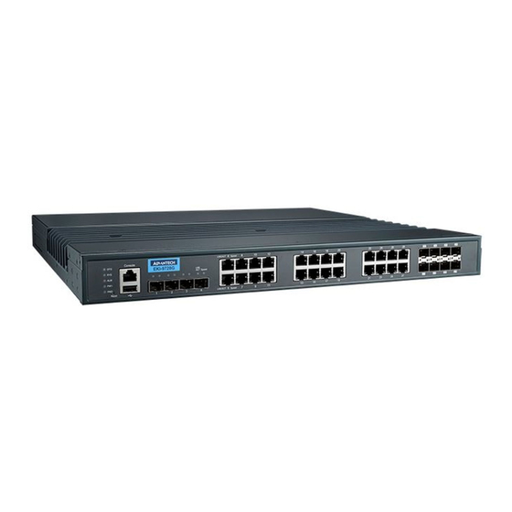
Page 20: Hardware Views
PWR1 RELAY2 RELAY1 V+ V- GND V+ V- GND Figure 1.2 Front View No. Item Description Terminal block PWR2 Connect cabling for power. Terminal block Connect cabling for alarms. Terminal block PWR1 Connect cabling for power. EKI-9728G Series User Manual... -
Page 21: Figure 1.3 System Led Panel
Power is being supplied to power input PWR2. Power is not being supplied to power input PWR1. DATA Green on Link 1G Blink green ACT 1G Amber on Link 10/100MB Blink amber ACT 10/100MB Link down EKI-9728G Series User Manual... -
Page 22: Dimensions
1.2.3 Dimensions Unit: mm Ø 6.8 x 10.3 OB Hole Figure 1.4 Dimensions EKI-9728G Series User Manual... -
Page 23: Switch Installation
Chapter Switch Installation... -
Page 24: Warnings
Caution! This unit may have more than one power supply connection. All connec- tions must be removed to de-energize the unit. Caution! The installation, replacement, or service of the device must be Only be performed by trained and qualified personnel. EKI-9728G Series User Manual... - Page 25 Warning! Airflow around the switch must be unrestricted. To prevent the switch from overheating, there must be the following minimum clearances: Top and bottom: 2.0 in. (50.8 mm) Sides: 2.0 in. (50.8 mm) Front: 2.0 in. (50.8 mm) EKI-9728G Series User Manual...
-
Page 26: Installation Guidelines
2.3.1 Connecting Hardware These instructions explain how to find a proper location for your Modbus Gateways, and how to connect to the network, hook up the power cable, and connect to the EKI- 9228G Series. EKI-9728G Series User Manual... -
Page 27: Verifying Switch Operation
Secure the switch. CF G Co nso SY S AL M EK I-9 72 8G LINK /AC PW 1 Spe ed PW 2 Spe ed Res et LINK /AC Spe ed Figure 2.2 Installing the Switch EKI-9728G Series User Manual... -
Page 28: Installing And Removing Sfp Modules
Position the SFP transceiver with the handle on top, see the following figure. Locate the triangular marking in the slot and align it with the bottom of the trans- ceiver. Insert the SFP transceiver into the slot until it clicks into place. EKI-9728G Series User Manual... -
Page 29: Figure 2.4 Installing An Sfp Transceiver
Insert the fiber cable into the transceiver. The connector snaps into place and locks. Figure 2.5 Attaching a Fiber Optic Cable to a Transceiver Repeat the previous procedures to install any additional SFP transceivers in the switch. The fiber port is now setup. EKI-9728G Series User Manual... -
Page 30: Removing Sfp Modules
Hold the handle on the transceiver and pull the transceiver out of the slot. Handle Figure 2.7 Removing an SFP Transceiver Note! Replace the dust plug on the slot if you are not installing a transceiver. The dust plug protects hardware from dust contamination. EKI-9728G Series User Manual... -
Page 31: Connecting The Switch To Ethernet Ports
RJ45 to RS232 serial cable between a COM port on your PC (9-pin D-sub female) and the switch’s RJ45 (RJ45) port, a wired connection for management can be established. To terminal or PC To console port Figure 2.9 Serial Console Cable Figure 2.10 DB 9 Pin Position EKI-9728G Series User Manual... -
Page 32: Power Supply Installation
V1+ terminal and the V1- terminal (PW1), see the following illus- trations. A Class 2 power supply is required to maintain a UL60950 panel listing. The chassis ground screw terminal should be tied to the panel or chassis ground. A EKI-9728G Series User Manual... -
Page 33: Considerations
Caution! Before connecting the device properly ground the device. Lack of a proper grounding setup may result in a safety risk and could be hazard- ous. EKI-9728G Series User Manual... -
Page 34: Wiring A Relay Contact
Caution! Do not block air ventilation holes. 2.9.4 Wiring a Relay Contact The following section details the wiring of the relay output. The terminal block on the EKI-9728G Series is wired and then installed onto the terminal receptor located on the EKI-9228G Series. RELAY2 RELAY1 Figure 2.13 Terminal Receptor: Relay Contact... -
Page 35: Reset Button
Reset configuration to factory default: Press and hold Reset button for 5 seconds. System reboot: Press and hold Reset button for 3 seconds. Note! Do NOT power off the Ethernet switch when loading default settings. EKI-9728G Series User Manual... -
Page 36: Configuration Utility
Chapter Configuration Utility... -
Page 37: First Time Setup
Secure Shell (SSH). An SNMP interface can be used to read/write many settings. Command Line Interface (CLI) can be used to read/write most settings. Initial setup must be done using an Ethernet connection (recommended) or the serial port. EKI-9728G Series User Manual... -
Page 38: Using The Graphical (Web) Interface
Fully Qualified Domain Name (FQDN) such as “domainname.org”. NTP Server: The IP address or domain name of an NTP (Network Time Proto- col) server from which the switch may retrieve the current time at startup. EKI-9728G Series User Manual... -
Page 39: Configuring The Ethernet Ports
Otherwise, the switch will use the fixed Ethernet port and the correspond- ing settings for it. Note! When 100f is selected for the SFP of a gigabit combination port, the cor- responding fixed Ethernet jack will be disabled unless it is changed back to 1000F. EKI-9728G Series User Manual... -
Page 40: Command Line Interface Configuration
To connect by Ethernet, open a command prompt window and type: telnet <switchip> (where <switchip> is the IP address of the switch) At the login prompt, type “cli” for the username and “admin” for the password. The switch will respond with “Managed switch configuration CLI ready”. EKI-9728G Series User Manual... -
Page 41: Web Browser Configuration
In the browser’s address bar, type the switch’s default IP address (192.168.1.1). The login screen displays. Enter the user default name and password (admin / admin). Click OK on the login screen to log in. The main interface displays. EKI-9728G Series User Manual... -
Page 42: Managing Switch
Chapter Managing Switch... -
Page 43: Log In
The following details the necessary steps to change the default password. To change the password: Navigate to System > Users > Accounts. Figure 4.2 System > Users > Accounts EKI-9728G Series User Manual... -
Page 44: System
Figure 4.4 System > AAA > Authentication List The following table describes the items in the previous figure. Item Description List Name The name of the authentication list. This field can be configured only when adding a new authentication list. EKI-9728G Series User Manual... - Page 45 Authentication Selection page. Refresh Click Refresh to update the screen. Click Add to add a new authentication list. See the following procedure. Edit Click Edit to edit the selected entries. EKI-9728G Series User Manual...
-
Page 46: Figure 4.5 System > Aaa > Authentication List > Add
CLI commands. The options available in this menu include the default Enable authentication lists as well as any user-configured Enable lists. To access this page, click System > AAA > Authentication Selection. Figure 4.6 System > AAA > Authentication Selection EKI-9728G Series User Manual... -
Page 47: Figure 4.7 System > Aaa > Authorization List
Privileged EXEC mode directly after a successful Login authentication. Network: Determines whether the user is permitted to access various network services. This authorization type applies to port- based access (IEEE 802.1X) rather than access to the CLI. EKI-9728G Series User Manual... -
Page 48: Figure 4.8 System > Aaa > Authorization List > Add
The authorization methods that can be used for the authorization list. Not all methods are available for all lists. To set the authorization method, select the method in the Available Methods field and click the right arrow to move it into the Selected Methods field. EKI-9728G Series User Manual... -
Page 49: Figure 4.9 System > Aaa > Authorization Selection
CLI by using a secure shell (SSH) session. Submit Click Submit to save the values and update the screen. Refresh Click Refresh to update the screen. Cancel Click Cancel to restore default value. EKI-9728G Series User Manual... -
Page 50: Figure 4.10 System > Aaa > Accounting List
The settings for this field are configured on the Accounting Selection page. Refresh Click Refresh to update the screen. Click Add to add a new accounting list. See the following procedure. Edit Click Edit to edit the selected entries. EKI-9728G Series User Manual... -
Page 51: Figure 4.11 System > Aaa > Accounting List > Add
For Terminal access methods, this list records the CLI commands a user executes and when each command is issued. To access this page, click System > AAA > Accounting Selection. Figure 4.12 System > AAA > Accounting Selection EKI-9728G Series User Manual... -
Page 52: Advanced Configuration
Bootp Automatic Enables or disables the BOOTP automatic mode. When enabled, the Mode DHCP server supports the allocation of automatic addresses for BOOTP clients. When disabled the DHCP server supports only static addresses for BOOTP clients. EKI-9728G Series User Manual... -
Page 53: Figure 4.14 System > Advanced Configuration > Dhcp Server > Excluded Addresses
Figure 4.15 System > Advanced Configuration > DHCP Server > Excluded Addresses > Add The following table describes the items in the previous figure. Item Description From The IP address to exclude. In a range of addresses, this value is the lowest address to exclude. EKI-9728G Series User Manual... -
Page 54: Figure 4.16 System > Advanced Configuration > Dhcp Server > Pool Summary
The amount of time the information the DHCP server allocates is valid. Refresh Click Refresh to update the screen. Click Add to add a new DHCP server pool. See the following procedure. Remove Click Remove to remove the selected entries. EKI-9728G Series User Manual... -
Page 55: Figure 4.17 System > Advanced Configuration > Dhcp Server > Pool Summary > Add
Manual pools. Host IP Address The IP address to offer the client. The function is only available for Manual pools. Host Mask The subnet mask to offer the client. The function is only available for Manual pools. EKI-9728G Series User Manual... -
Page 56: Figure 4.18 System > Advanced Configuration > Dhcp Server > Pool Configuration
Figure 4.18 System > Advanced Configuration > DHCP Server > Pool Configuration The following table describes the items in the previous figure. Item Description Pool Name Select the pool to configure. The menu includes all pools that have been configured on the device. EKI-9728G Series User Manual... - Page 57 60 days. For a Manual binding, an infinite lease period never expires. Lease Duration The number of Days, Hours, and Minutes the lease is valid. This field cannot be configured if the Lease Expiration is disabled. EKI-9728G Series User Manual...
-
Page 58: Figure 4.19 System > Advanced Configuration > Dhcp Server > Pool Options
Figure 4.19 System > Advanced Configuration > DHCP Server > Pool Options The following table describes the items in the previous figure. Item Description Pool Name Select the pool to configure. The menu includes all pools that have been configured on the device. EKI-9728G Series User Manual... -
Page 59: Figure 4.20 System > Advanced Configuration > Dhcp Server > Pool Options > Add Vendor Option
Figure 4.20 System > Advanced Configuration > DHCP Server > Pool Options > Add Vendor Option The following table describes the items in the previous figure. Item Description Option Code The number that uniquely identifies the option. EKI-9728G Series User Manual... -
Page 60: Figure 4.21 System > Advanced Configuration > Dhcp Server > Pool Options > Edit
Figure 4.22 System > Advanced Configuration > DHCP Server > Bindings The following table describes the items in the previous figure. Item Description IP Address The IP Address of the DHCP client. Hardware Address The MAC address of the DHCP client. EKI-9728G Series User Manual... -
Page 61: Figure 4.23 System > Advanced Configuration > Dhcp Server > Statistics
A client sends a decline message if the DHCP client detects that the IP address offered by the DHCP server is already in use on the network. The server then marks the address as unavailable. EKI-9728G Series User Manual... -
Page 62: Figure 4.24 System > Advanced Configuration > Dhcp Server > Conflicts
Conflicts. Figure 4.24 System > Advanced Configuration > DHCP Server > Conflicts The following table describes the items in the previous figure. Item Description IP Address The IP address that has been detected as a duplicate. EKI-9728G Series User Manual... -
Page 63: Figure 4.25 System > Advanced Configuration > Dns > Configuration
The number of times the DNS client should attempt to send DNS queries to a DNS server on the network. Response Timeout The number of seconds the DNS client should wait for a response to a (seconds) DNS query. EKI-9728G Series User Manual... -
Page 64: Figure 4.26 System > Advanced Configuration > Dns > Ip Mapping
The function is only available for Dynamic entries. Dynamic Type The type of address in the entry, for example IP or (less common) X.121. The function is only available for Dynamic entries. Refresh Click Refresh to update the screen. EKI-9728G Series User Manual... -
Page 65: Figure 4.27 System > Advanced Configuration > Dns > Ip Mapping > Add
To access this page, click System > Advanced Configuration > DNS > Source Interface Configuration. Figure 4.28 System > Advanced Configuration > DNS > Source Interface Configuration EKI-9728G Series User Manual... -
Page 66: Figure 4.29 System > Advanced Configuration > Email Alerts > Global
Use the Email Alert Global Configuration page to configure the common settings for log messages sent by the switch. To access this page, click System > Advanced Configuration > Email Alerts > Global. Figure 4.29 System > Advanced Configuration > Email Alerts > Global EKI-9728G Series User Manual... -
Page 67: Figure 4.30 System > Advanced Configuration > Email Alerts > Test
Specifies the text contained in the body of the email alert test message. Submit Click Submit to save the values and update the screen. Refresh Click Refresh to update the screen. Cancel Click Cancel to restore default value. EKI-9728G Series User Manual... -
Page 68: Figure 4.31 System > Advanced Configuration > Email Alerts > Server
Specifies the type of authentication to use with the mail server, which can be TLSv1 (SMTP over SSL) or None (no authentication is required). Port Email Specifies the TCP port that alerts are sent to on the SMTP server. EKI-9728G Series User Manual... -
Page 69: Figure 4.33 System > Advanced Configuration > Email Alerts > Statistics
Specify the text to be displayed in the subject of the email alert message for the selected message type. Submit Click Submit to save the values and update the screen. Refresh Click Refresh to update the screen. EKI-9728G Series User Manual... -
Page 70: Figure 4.35 System > Advanced Configuration > Email Alerts > Address
Cisco devices running the Cisco Discovery Protocol (CDP). ISDP is used to share information between neighboring devices. FASTPATH software participates in the CDP protocol and is able to both discover and be discovered by other CDP supporting devices. Global EKI-9728G Series User Manual... -
Page 71: Figure 4.37 System > Advanced Configuration > Isdp > Global
Use the ISDP Cache Table page to view information about other devices the switch has discovered through the ISDP. To access this page, click System > Advanced Configuration > ISDP > Cache Table. Figure 4.38 System > Advanced Configuration > ISDP > Cache Table EKI-9728G Series User Manual... -
Page 72: Figure 4.39 System > Advanced Configuration > Isdp > Interface
The following table describes the items in the previous figure. Item Description Interface The interface on which ISDP can be enabled or disabled. In the Edit ISDP Mode window, this field identifies the interfaces that are being configured. EKI-9728G Series User Manual... -
Page 73: Figure 4.40 System > Advanced Configuration > Isdp > Statistics
The number of times the IP address of a neighbor could not be added Table Full to the neighbor entry because the IP address table was full. Refresh Click Refresh to update the screen. Clear Click Clear to reset all statistic to zero. EKI-9728G Series User Manual... -
Page 74: Figure 4.41 System > Advanced Configuration > Link Dependency > Group
Click Add to add a new group. See the following procedure. Edit Click Edit to edit the selected entries. Remove Click Remove to remove the selected entries. Details Click Detail to open the Group Entry Details window. EKI-9728G Series User Manual... -
Page 75: Figure 4.42 System > Advanced Configuration > Link Dependency > Group > Add
To access this page, click System > Advanced Configuration > LLPF > Configuration. Figure 4.43 System > Advanced Configuration > LLPF > Configuration EKI-9728G Series User Manual... -
Page 76: Figure 4.44 System > Advanced Configuration > Protection > Denial Of Service
DoS attacks. You can configure your system to monitor and block these types of attacks: To access this page, click System > Advanced Configuration > Protection > Denial of Service. Figure 4.44 System > Advanced Configuration > Protection > Denial of Service EKI-9728G Series User Manual... - Page 77 Enable this option to allow the device to drop fragmented ICMP packets. Submit Click Submit to save the values and update the screen. Refresh Click Refresh to update the screen. Cancel Click Cancel to restore default value. EKI-9728G Series User Manual...
-
Page 78: Figure 4.45 System > Advanced Configuration > Sdm > Sdm
(also known as a collector). To access this page, click System > Advanced Configuration > sFlow > Agent. Figure 4.46 System > Advanced Configuration > sFlow > Agent EKI-9728G Series User Manual... -
Page 79: Figure 4.47 System > Advanced Configuration > Sflow > Receiver
The version of sFlow datagrams that the sFlow agent should send to the sFlow receiver. Monitor Session Monitor session to enable sFlow hardware feature. Refresh Click Refresh to update the screen. Edit Click Edit to edit the selected entries. Clear Click Clear to clear the selected entry. EKI-9728G Series User Manual... -
Page 80: Figure 4.48 System > Advanced Configuration > Sflow > Poller
Poller Interval The maximum number of seconds between successive samples of (Seconds) the counters associated with this data source. A sampling interval of 0 disables counter sampling. EKI-9728G Series User Manual... -
Page 81: Figure 4.50 System > Advanced Configuration > Sflow > Sampler
The ID of the MAC ACL to apply to traffic from the sampler. Refresh Click Refresh to update the screen. Click Add to add a new sampler data. See the following procedure. Edit Click Edit to edit the selected entries. Remove Click Remove to remove the selected entries. EKI-9728G Series User Manual... -
Page 82: Figure 4.51 System > Advanced Configuration > Sflow > Sampler > Add
This allows security devices, such as firewalls, to identify all source packets coming from a specific device. To access this page, click System > Advanced Configuration > sFlow > Source Interface Configuration. Figure 4.52 System > Advanced Configuration > sFlow > Source Interface Configuration EKI-9728G Series User Manual... -
Page 83: Figure 4.53 System > Advanced Configuration > Snmp > Community
Figure 4.53 System > Advanced Configuration > SNMP > Community The following table describes the items in the previous figure. Item Description Community Name Community name used in SNMPv1/v2 packets. This is configured in the client and identifies the access the user may connect with. EKI-9728G Series User Manual... -
Page 84: Figure 4.54 System > Advanced Configuration > Snmp > Community > Add Community
Community Group The following table describes the items in the previous figure. Item Description Community Name Community name used in SNMPv1/v2 packets. This is configured in the client and identifies the access the user may connect with. EKI-9728G Series User Manual... -
Page 85: Figure 4.56 System > Advanced Configuration > Snmp > Trap Receiver V1/V2
UDP port value is used. Refresh Click Refresh to update the screen. Click Add to add a new SNMP trap receiver. See the following procedure. Remove Click Remove to remove the selected entries. EKI-9728G Series User Manual... -
Page 86: Figure 4.57 System > Advanced Configuration > Snmp > Trap Receiver V1/V2 > Add
The UDP port on the SNMP management host that will receive the SNMP notifications. If no value is specified when configuring a receiver, the default UDP port value is used. Submit Click Submit to save the values. Cancel Click Cancel to close the window. EKI-9728G Series User Manual... -
Page 87: Figure 4.58 System > Advanced Configuration > Snmp > Trap Receiver V3
UDP port value is used. Refresh Click Refresh to update the screen. Click Add to add a new SNMP trap receiver. See the following procedure. Remove Click Remove to remove the selected entries. EKI-9728G Series User Manual... -
Page 88: Figure 4.59 System > Advanced Configuration > Snmp > Trap Receiver V3 > Add
The UDP port on the SNMP management host that will receive the SNMP notifications. If no value is specified when configuring a receiver, the default UDP port value is used. Submit Click Submit to save the values. Cancel Click Cancel to close the window. EKI-9728G Series User Manual... -
Page 89: Figure 4.60 System > Advanced Configuration > Snmp > Supported Mibs
To access this page, click System > Advanced Configuration > SNMP > Access Control Group. Figure 4.61 System > Advanced Configuration > SNMP > Access Control Group The following table describes the items in the previous figure. Item Description Group Name The name that identifies the SNMP group. EKI-9728G Series User Manual... -
Page 90: Figure 4.62 System > Advanced Configuration > Snmp > Access Control Group > Add
Click Remove to remove the selected entries. To add a new access control group: Click System > Advanced Configuration > SNMP > Access Control Group > Add. Figure 4.62 System > Advanced Configuration > SNMP > Access Control Group > Add EKI-9728G Series User Manual... -
Page 91: Figure 4.63 System > Advanced Configuration > Snmp > User Security Model
The SNMP User Security Model page provides the capability to configure the SNMP V3 user accounts. To access this page, click System > Advanced Configuration > SNMP > User Security Model. Figure 4.63 System > Advanced Configuration > SNMP > User Security Model EKI-9728G Series User Manual... -
Page 92: Figure 4.64 System > Advanced Configuration > Snmp > User Security Model > Add
Figure 4.64 System > Advanced Configuration > SNMP > User Security Model > The following table describes the items in the previous figure. Item Description Engine ID Type Specifies the engine ID type to be used. Local Remote EKI-9728G Series User Manual... -
Page 93: Figure 4.65 System > Advanced Configuration > Snmp > Source Interface Configuration
To access this page, click System > Advanced Configuration > SNMP > Source Interface Configuration. Figure 4.65 System > Advanced Configuration > SNMP > Source Interface Configuration EKI-9728G Series User Manual... -
Page 94: Figure 4.66 System > Advanced Configuration > Snmp > Server Configuration
Submit Click Submit to save the values and update the screen. Refresh Click Refresh to update the screen. Cancel Click Cancel to restore default value. EKI-9728G Series User Manual... -
Page 95: Figure 4.67 System > Advanced Configuration > Sntp > Global Configuration
Specifies the number of current valid unicast server entries configured Configured for this client. Submit Click Submit to save the values and update the screen. Refresh Click Refresh to update the screen. Cancel Click Cancel to restore default value. EKI-9728G Series User Manual... -
Page 96: Figure 4.68 System > Advanced Configuration > Sntp > Global Status
Server Stratum Specifies the claimed stratum of the server for the last received valid packet. Stratums define the accuracy of the reference clock. The higher the stratum (where zero is the highest), the more accurate the clock. EKI-9728G Series User Manual... -
Page 97: Figure 4.69 System > Advanced Configuration > Sntp > Server Configuration
Specifies the NTP version running on the server. Refresh Click Refresh to update the screen. Click Add to add a new SNTP server. See the following procedure. Edit Click Edit to edit the selected entries. Remove Click Remove to remove the selected entries. EKI-9728G Series User Manual... -
Page 98: Figure 4.70 System > Advanced Configuration > Sntp > Server Configuration > Add
The local date and time (UTC) included in the response from this server that was used to update the system clock. Last Attempt Time Specifies the local date and time (UTC) that this SNTP server was last queried. EKI-9728G Series User Manual... -
Page 99: Figure 4.72 System > Advanced Configuration > Sntp > Source Interface Configuration
This allows security devices, such as firewalls, to identify all source packets coming from a specific device. To access this page, click System > Advanced Configuration > SNTP > Source Interface Configuration. Figure 4.72 System > Advanced Configuration > SNTP > Source Interface Configuration EKI-9728G Series User Manual... -
Page 100: Figure 4.73 System > Advanced Configuration > Time Ranges > Configuration
To access this page, click System > Advanced Configuration > Time Ranges > Configuration. Figure 4.73 System > Advanced Configuration > Time Ranges > Configuration EKI-9728G Series User Manual... -
Page 101: Figure 4.74 System > Advanced Configuration > Time Ranges > Configuration > Add
The time range entries use the system time for the time periods in which they take effect. Make sure you configure the SNTP server settings so that the SNTP client on the switch can obtain the correct date and time from the server. EKI-9728G Series User Manual... -
Page 102: Figure 4.75 System > Advanced Configuration > Time Ranges > Entry Configuration
To add a new absolute time range: Click System > Advanced Configuration > Time Ranges > Entry Configuration > Add Absolute. Figure 4.76 System > Advanced Configuration > Time Ranges > Entry Configuration > Add Absolute EKI-9728G Series User Manual... -
Page 103: Figure 4.77 System > Advanced Configuration > Time Ranges > Entry Configuration > Add Periodic
Figure 4.77 System > Advanced Configuration > Time Ranges > Entry Configuration > Add Periodic The following table describes the items in the previous figure. Item Description Time Range Name The time range configuration that will include the Periodic time range entry. EKI-9728G Series User Manual... -
Page 104: Figure 4.78 System > Advanced Configuration > Time Zone > Summary
The current time on the system clock. This time is used to provide time stamps on log messages. Additionally, some CLI show commands include the time in the command output. Zone The acronym that represents the time zone. Date The current date on the system. EKI-9728G Series User Manual... -
Page 105: Figure 4.79 System > Advanced Configuration > Time Zone > Time Zone
To access this page, click System > Advanced Configuration > Time Zone > Time Zone. Figure 4.79 System > Advanced Configuration > Time Zone > Time Zone The following table describes the items in the previous figure. Item Description Time Zone EKI-9728G Series User Manual... -
Page 106: Figure 4.80 System > Advanced Configuration > Time Zone > Summer Time
To access this page, click System > Advanced Configuration > Time Zone > Summer Time. Figure 4.80 System > Advanced Configuration > Time Zone > Summer Time EKI-9728G Series User Manual... - Page 107 The acronym associated with the time zone when summer time is in effect. Submit Click Submit to save the values and update the screen. Refresh Click Refresh to update the screen. Cancel Click Cancel to restore default value. EKI-9728G Series User Manual...
-
Page 108: Figure 4.81 System > Advanced Configuration > Trap Manager > Trap Log
Trap Provides information about the trap. Refresh Click Refresh to update the screen. Clear Log Click Clear Log to clear the current entries from the log file and resets the counters. EKI-9728G Series User Manual... -
Page 109: Figure 4.82 System > Advanced Configuration > Trap Manager > Trap Flags
Use the Global page to view and modify the CPU Traffic Filter settings on the device. To access this page, click System > Advanced Configuration > CPU Traffic Filter > Global. Figure 4.83 System > Advanced Configuration > CPU Traffic Filter > Global EKI-9728G Series User Manual... -
Page 110: Figure 4.84 System > Advanced Configuration > Cpu Traffic Filter > Filter Configuration
Only two software filters are used (one filter each direction Tx or Rx) with condition matching as one, many or all in the below list in Tx or Rx or Both direction. Filter This shows specific filters for each direction. EKI-9728G Series User Manual... - Page 111 Source / Destination UDP Port. Refresh Click Refresh to update the screen. Edit Click Edit to edit the selected entries. Remove Click Remove to remove the selected entries. EKI-9728G Series User Manual...
-
Page 112: Figure 4.85 System > Advanced Configuration > Cpu Traffic Filter > Interfaces
Only two software filter is supported (one filter each direction Tx or Rx) with condition matching as one, many or all in the below list in Tx or Rx or Both direction. Submit Click Submit to save the values. Cancel Click Cancel to close the window. EKI-9728G Series User Manual... -
Page 113: Figure 4.87 System > Advanced Configuration > Cpu Traffic Filter > Statistics
The counter statistics for all interfaces, which are associated with Tx direction. Received The counter statistics for all interfaces, which are associated with Rx direction. Refresh Click Refresh to update the screen. Clear Click Clear to clear the filter summary. EKI-9728G Series User Manual... -
Page 114: Basic Configuration
Specify the number of seconds a dynamic address should remain in the MAC address table after it has been learned. EKI-9728G Series User Manual... -
Page 115: Configuration Storage
It is possible that the IP address of the switch will change. If this occurs you will need to determine the new IP address to access the device using the web. EKI-9728G Series User Manual... -
Page 116: Figure 4.93 System > Configuration Storage > Erase Startup
Startup Config: The file that contains the configuration that loads when the system boots. Backup Config: The file that is used to store a copy of the running or startup configuration. Submit Click Submit to save the values and update the screen. EKI-9728G Series User Manual... -
Page 117: Connectivity
The IP subnet mask for the interface. If the Network Configuration Protocol is None, you can manually configure a static subnet mask. If the Network Configuration Protocol is BOOTP or DHCP, this field displays the subnet mask that was dynamically acquired (if any). EKI-9728G Series User Manual... -
Page 118: Figure 4.96 System > Connectivity > Ipv6
Enables or disables the IPv6 administrative mode on the network interface. Network Specify whether the device should attempt to acquire network Configuration information from a DHCPv6 server. Selecting None disables the Protocol DHCPv6 client on the network interface. EKI-9728G Series User Manual... -
Page 119: Figure 4.97 System > Connectivity > Ipv6 Neighbors
Figure 4.97 System > Connectivity > IPv6 Neighbors The following table describes the items in the previous figure. Item Description IPv6 Address The IPv6 address of a neighbor device that has been reachable on the local link through the network interface. EKI-9728G Series User Manual... -
Page 120: Figure 4.98 System > Connectivity > Ipv6 Neighbors > Add
The IPv6 address of a neighbor device that has been reachable on the local link through the network interface. MAC Address The MAC address of the neighboring device. Submit Click Submit to save the values. Cancel Click Cancel to close the window. EKI-9728G Series User Manual... -
Page 121: Figure 4.99 System > Connectivity > Service Port Ipv4
Submit Click Submit to save the values and update the screen. Refresh Click Refresh to update the screen. Renew DHCP Lease Click Renew DHCP Lease to renew DHCP lease. Cancel Click Cancel to restore default value. EKI-9728G Series User Manual... -
Page 122: Figure 4.100 System > Connectivity > Service Port Ipv6
Lists the IPv6 addresses on the service port interface that have been Addresses dynamically configured through IPv6 auto configuration or DHCPv6. Default IPv6 Routers Lists the IPv6 address of each default router that has been automatically configured through IPv6 router discovery. EKI-9728G Series User Manual... -
Page 123: Figure 4.101 System > Connectivity > Service Port Ipv6 Neighbors
The amount of time that has passed since the neighbor entry was last updated. Refresh Click Refresh to update the screen. Click Add to add a new service port IPv6 neighbor. See the following procedure. Remove Click Remove to remove the selected entries. EKI-9728G Series User Manual... -
Page 124: Firmware
The device can store up to two software images in permanent storage. The dual image feature allows you to upgrade the device without deleting the older software image. To access this page, click System > Firmware > Status. Figure 4.104 System > Firmware > Status EKI-9728G Series User Manual... -
Page 125: Figure 4.105 System > Firmware > Configuration And Upgrade
To delete the backup image from permanent storage, click button. You must confirm the action before the image is deleted. Next Active Select the image version to load the next time this unit reboots. EKI-9728G Series User Manual... -
Page 126: Figure 4.106 System > Firmware > Autoinstall
TFTP client on the device tries to use unicast requests before reverting to broadcast requests. Status The current status of the AutoInstall process. Submit Click Submit to save the values and update the screen. EKI-9728G Series User Manual... -
Page 127: Logs
The component that issued the log entry. Description The text description for the log entry. Refresh Click Refresh to update the screen. Clear Log Click Clear Log to clear the buffered log messages and resets the counters. EKI-9728G Series User Manual... -
Page 128: Figure 4.108 System > Logs > Event Log
The only correlation between any two entries in the event log is the relative amount of time after a system reset that the event occurred. Refresh Click Refresh to update the screen. EKI-9728G Series User Manual... -
Page 129: Figure 4.109 System > Logs > Persistent Log
To access this page, click System > Logs > Hosts. Figure 4.110 System > Logs > Hosts The following table describes the items in the previous figure. Item Description Host The IP address or DNS-resolvable host name of the remote host to receive log messages. EKI-9728G Series User Manual... -
Page 130: Figure 4.111 System > Logs > Hosts > Add
Severity level threshold for log messages. All log messages with a severity level at and above the configured level are forwarded to the logging host. Submit Click Submit to save the values. Cancel Click Cancel to close the window. EKI-9728G Series User Manual... -
Page 131: Figure 4.112 System > Logs > Configuration
Severity Filter Select the severity of the messages to be logged. All messages at and above the selected threshold are logged to the console. See the previous severity filter description for more information about each severity level. EKI-9728G Series User Manual... -
Page 132: Figure 4.113 System > Logs > Source Interface Configuration
When the selected Type is Interface, select the physical port to use as the source interface. VLAN ID When the selected Type is VLAN, select the VLAN to use as the source interface. The menu contains only the VLAN IDs for VLAN routing interfaces. EKI-9728G Series User Manual... -
Page 133: Figure 4.114 System > Logs > Statistics
Messages Relayed The number of log messages successfully relayed to a remote syslog server. Messages forwarded to multiple hosts are counted once for each host. Refresh Click Refresh to update the screen. EKI-9728G Series User Manual... -
Page 134: Management Access
SSH connections cannot be established. Submit Click Submit to save the values and update the screen. Refresh Click Refresh to update the screen. Cancel Click Cancel to restore default value. EKI-9728G Series User Manual... -
Page 135: Figure 4.116 System > Management Access > Telnet
An outbound Telnet session is a Telnet session initiated from the CLI of the device to the Telnet client on a remote device. To access this page, click System > Management Access > Outbound Telnet. Figure 4.117 System > Management Access > Outbound Telnet EKI-9728G Series User Manual... -
Page 136: Figure 4.118 System > Management Access > Serial
Indicates whether hardware flow control is enabled or disabled on the serial port. Submit Click Submit to save the values and update the screen. Refresh Click Refresh to update the screen. Cancel Click Cancel to restore default value. EKI-9728G Series User Manual... -
Page 137: Figure 4.119 System > Management Access > Cli Banner
HTTP Session Soft HTTP session inactivity timeout value. A logged-in user that does not Time Out (Minutes) exhibit any HTTP activity for this amount of time is automatically logged out of the HTTP session. EKI-9728G Series User Manual... -
Page 138: Figure 4.121 System > Management Access > Https
HTTPS session is automatically logged out after this amount of time regardless of the amount of HTTPS activity that occurs. Maximum Number of The maximum number of HTTPS sessions that can be connected to HTTPS Sessions the device simultaneously. EKI-9728G Series User Manual... -
Page 139: Figure 4.122 System > Management Access > Ssh
The following table describes the items in the previous figure. Item Description SSH Admin Mode Enables or disables the SSH server administrative mode. When this mode is enabled, the device can be accessed by using an SSH client on a remote system. EKI-9728G Series User Manual... - Page 140 Deletes the SSL certificate. This button is available only if an SSL certificate is present on the device. Submit Click Submit to save the values and update the screen. Refresh Click Refresh to update the screen. Cancel Click Cancel to restore default value. EKI-9728G Series User Manual...
-
Page 141: Management Security
Specifies the network mask of the source IP address. VLAN Vlan number. Port Channel Port channels, also known as Link Aggregation Groups (LAGs), allow one or more full-duplex Ethernet links of the same speed to be aggregated together. EKI-9728G Series User Manual... -
Page 142: Passwords
Submit Click Submit to save the values and update the screen. Refresh Click Refresh to update the screen. Cancel Click Cancel to restore default value. EKI-9728G Series User Manual... -
Page 143: Figure 4.125 System > Passwords > Enable Password
Minimum Number of The minimum number of upper-case letters that a valid password Uppercase Letters must contain. EKI-9728G Series User Manual... -
Page 144: Figure 4.127 System > Passwords > Last Password
Use the Last Password Result page view information about the last attempt to set a user password. If the password set was unsuccessful, a reason for the failure is given. To access this page, click System > Passwords > Last Password. Figure 4.127 System > Passwords > Last Password EKI-9728G Series User Manual... -
Page 145: Port
Use the Port Summary page to view the settings for all physical ports on the platform. To access this page, click System > Port > Summary. Figure 4.129 System > Port > Summary The following table describes the items in the previous figure. Item Description Interface Identifies the port or LAG. EKI-9728G Series User Manual... - Page 146 Indicates whether the link is up or down. The link is the physical connection between the port or LAG and the interface on another device. Refresh Click Refresh to update the screen. Edit Click Edit to edit the selected entries. EKI-9728G Series User Manual...
-
Page 147: Figure 4.130 System > Port > Description
To access this page, click System > Port > Cable Test. Figure 4.131 System > Port > Cable Test The following table describes the items in the previous figure. Item Description Interface Click the drop-down menu to select the port with the connected cable to test. EKI-9728G Series User Manual... -
Page 148: Figure 4.132 System > Port > Mirroring
Use the Multiple Port Mirroring page to define port mirroring sessions. To access this page, click System > Port > Mirroring. Figure 4.132 System > Port > Mirroring EKI-9728G Series User Manual... - Page 149 Click Configure Source to configure one or more source ports or a VLAN for the mirroring session and to determine which traffic is mirrored (Tx, Rx, or both). Remove Source Click Remove Source to remove the selected source ports. EKI-9728G Series User Manual...
-
Page 150: Figure 4.133 System > Port > Mirroring Summary
Possible values for source ports are: Tx and Rx: Both ingress and egress traffic. Rx: Ingress traffic only. Tx: Egress traffic only. Refresh Click Refresh to update the screen. EKI-9728G Series User Manual... -
Page 151: Slot
Figure 4.135 System > Slot > Configuration > Add The following table describes the items in the previous figure. Item Description Unit Identifies the unit number of the device (in the stack of devices) on which to add the new card. EKI-9728G Series User Manual... -
Page 152: Figure 4.136 System > Slot > Supported Cards
Card Description Description of the supported card, which might include the manufacturer's product number and information about number and speed of the supported interfaces. Refresh Click Refresh to update the screen. EKI-9728G Series User Manual... -
Page 153: Statistics
The highest number of entries that have existed in the MAC address table or VLAN database since the most recent reboot. Maximum Allowed The maximum number of statically configured or dynamically learned entries allowed in the MAC address table or VLAN database. EKI-9728G Series User Manual... -
Page 154: Figure 4.138 System > Statistics > System > Port Summary
Tx Errors The number of outbound packets that could not be transmitted because of errors. Tx Collisions The best estimate of the total number of collisions on this Ethernet segment. Refresh Click Refresh to update the screen. EKI-9728G Series User Manual... -
Page 155: Figure 4.139 System > Statistics > System > Port Detailed
(excluding framing bits but including FCS octets). 256-511 Octets The total number of packets (including bad packets) received or transmitted that were between 256 and 511 octets in length inclusive (excluding framing bits but including FCS octets). EKI-9728G Series User Manual... - Page 156 The total number of packets transmitted or received by this interface that had a length (excluding framing bits, but including FCS octets) of between 64 and 1518 octets, inclusive, but had a bad Frame Check Sequence (FCS) with an integral number of octets. EKI-9728G Series User Manual...
- Page 157 The total number of packets received that had a length (excluding framing bits, but including FCS octets) of between 64 and 1518 octets, inclusive, but had a bad Frame Check Sequence (FCS) with a non- integral number of octets. EKI-9728G Series User Manual...
-
Page 158: Figure 4.140 System > Statistics > System > Network Dhcpv6
Number of DHCPv6 advertisement messages received from one or Packets Received more DHCPv6 servers in response to the client's solicit message. Reply Packets Number of DHCPv6 reply messages received from one or more Received DHCPv6 servers in response to the client's request message. EKI-9728G Series User Manual... -
Page 159: Figure 4.141 System > Statistics > Time Based > Group
(manually or through SNTP) before using this feature. To access this page, click System > Statistics > Time Based > Group. Figure 4.141 System > Statistics > Time Based > Group EKI-9728G Series User Manual... - Page 160 CTRL + click each interface to include in the group. Refresh Click Refresh to update the screen. Click Add to add a new time based group. See the following procedure. Remove Click Remove to remove the selected entries. EKI-9728G Series User Manual...
-
Page 161: Figure 4.142 System > Statistics > Time Based > Group > Add
The interface or interfaces on which data is collected. To select multiple interfaces when adding a new group, CTRL + click each interface to include in the group. Submit Click Submit to save the values. Cancel Click Cancel to close the window. EKI-9728G Series User Manual... -
Page 162: Figure 4.143 System > Statistics > Time Based > Flow Based
Only traffic on the specified interfaces is checked against the rule. Refresh Click Refresh to update the screen. Click Add to add a new time based flow. See the following procedure. Remove Click Remove to remove the selected entries. EKI-9728G Series User Manual... -
Page 163: Figure 4.144 System > Statistics > Time Based > Flow Based > Add
The UDP source port to match in the UDP header. Destination UDP Port The UDP destination port to match in the UDP header. Submit Click Submit to save the values. Cancel Click Cancel to close the window. EKI-9728G Series User Manual... -
Page 164: Status
Ethernet MAC address assignment so a single ARP cache is employed. To access this page, click System > Status > ARP Cache. Figure 4.146 System > Status > ARP Cache EKI-9728G Series User Manual... -
Page 165: Figure 4.147 System > Status > Resource Status
CPU utilization, expressed as a percentage, that is used by the entire system for each of the specified time intervals. Task Name System task name. 5 Seconds The percentage amount of CPU utilization consumed by the corresponding task in the last 5 seconds. EKI-9728G Series User Manual... -
Page 166: Figure 4.148 System > Status > Resource Configuration
Submit Click Submit to save the values and update the screen. Refresh Click Refresh to update the screen. Cancel Click Cancel to restore default value. EKI-9728G Series User Manual... -
Page 167: Summary
The current time in system. Device Information Machine Type The device hardware type or product family. Machine Model The model identifier, which is usually related to the Machine Type. Serial Number The unique device serial number. EKI-9728G Series User Manual... -
Page 168: Figure 4.150 System > Summary > Description
The name used to identify this device. The factory default is blank. System Location The location of this device. The factory default is blank. System Contact The contact person for this device. The factory default is blank. EKI-9728G Series User Manual... -
Page 169: Figure 4.151 System > Summary > Inventory
For example, if the release is 1, the version is 2 and the maintenance number is 4, the format is 1.2.4. Hardware Version The device hardware version. Build Version The software trunk version. EKI-9728G Series User Manual... -
Page 170: Figure 4.152 System > Summary > Mac Address Table
MAC address can be reached. Interface Index The Interface Index of the MIB interface table entry associated with the source port. This value helps identify an interface when using SNMP to manage the device. EKI-9728G Series User Manual... -
Page 171: Users
Only a user with Read/Write privileges may alter data on this screen, and only one account can exist with Read/Write privileges. To access this page, click System > Users > Accounts. Figure 4.153 System > Users > Accounts EKI-9728G Series User Manual... -
Page 172: Figure 4.154 System > Users > Accounts > Add
The following table describes the items in the previous figure. Item Description User Name A unique ID or name used to identify this user account. Password The password assigned to this user. Confirm Re-enter the password to confirm that you have entered it correctly. EKI-9728G Series User Manual... -
Page 173: Figure 4.155 System > Users > Auth Server Users
See the following procedure. Edit Click Edit to change the password information for the selected user. Remove Click Remove to remove the selected entries. Clear All User Click Clear All User to remove all users from the database. EKI-9728G Series User Manual... -
Page 174: Figure 4.156 System > Users > Auth Server Users > Add
Shows the amount of time in hours, minutes, and seconds that the logged-on user has been inactive. Session Time Shows the amount of time in hours, minutes, and seconds since the user logged onto the system. EKI-9728G Series User Manual... -
Page 175: Figure 4.158 System > Users > User Domain Name
To access this page, click System > Users > Task Groups. Figure 4.159 System > Users > Task Groups The following table describes the items in the previous figure. Item Description Task Group The task group name. Description The associated description for task group name. EKI-9728G Series User Manual... -
Page 176: Figure 4.160 System > Users > Task Groups > Add
To access this page, click System > Users > User Groups. Figure 4.161 System > Users > User Groups The following table describes the items in the previous figure. Item Description User Group The user group name. EKI-9728G Series User Manual... -
Page 177: Utilities
The following table describes the items in the previous figure. Item Description Generate Core Dump Generates core dump file on demand. before reset Reset Click Reset to initiates the system reset action after displaying a confirmation message. EKI-9728G Series User Manual... -
Page 178: Figure 4.164 System > Utilities > Ping
The results of the ping test, which includes information about the reply (if any) received from the host. Start Click Start to start the ping test. The device sends the specified number of ping packets to the host. Stop Click Stop to interrupts the current ping test. EKI-9728G Series User Manual... -
Page 179: Figure 4.165 System > Utilities > Ping Ipv6
Interface is selected as source option. Results The results of the ping test, which includes information about the reply (if any) received from the host. Submit Click Submit to start the ping test. EKI-9728G Series User Manual... -
Page 180: Figure 4.166 System > Utilities > Traceroute
Interface Loopback, allowing the entry of the related information. IP Address Enabled if IP Address option is selected from Source setting. Interface Enabled if Interface option is selected from Source setting. Interface Loopback Enabled if Loopback option is selected from Source setting. EKI-9728G Series User Manual... - Page 181 The Test Attempt value shows the number of probes sent. The Test Success value shows the number of probes that received a response. Start Click Start to initiates the TraceRoute. Stop Click Stop to interrupts the running TraceRoute. EKI-9728G Series User Manual...
-
Page 182: Figure 4.167 System > Utilities > Traceroute Ipv6
ICMPv6 Port Unreachable message. Size (Bytes) The size of probe payload in bytes. Source The source IP address or interface to use when sending the trace route command. If source is not required, select None as source option. EKI-9728G Series User Manual... -
Page 183: Figure 4.168 System > Utilities > Ip Address Conflict
An IP address conflict can make both this system and the system with the same IP address unusable for network operation. To access this page, click System > Utilities > IP Address Conflict. Figure 4.168 System > Utilities > IP Address Conflict EKI-9728G Series User Manual... -
Page 184: Figure 4.169 System > Utilities > Transfer
TFTP, or FTP, click the download icon in the same row as the desired transfer protocol. The File Download window appears. Configure the information for the file transfer (described below), and click the download icon to the right of the Progress field to begin the transfer. EKI-9728G Series User Manual... - Page 185 Progress: Represents the completion percentage of the file transfer. The file transfer begins after you complete the required fields and click the upload icon to the right of this field. Status: Provides information about the status of the file transfer. EKI-9728G Series User Manual...
- Page 186 Parameter file (PEM Encoded) to the device. Note: To download SSH key files, SSH must be administratively disabled, and there can be no active SSH sessions. To down- load SSL related files, HTTPS must be administratively dis- abled. EKI-9728G Series User Manual...
-
Page 187: Figure 4.170 System > Utilities > Digital Signature Verification
Verify the digital signature of downloaded code image files. Configuration Verify the digital signature of downloaded configuration script files. Submit Click Submit to save the values and update the screen. Refresh Click Refresh to update the screen. Cancel Click Cancel to restore default value. EKI-9728G Series User Manual... -
Page 188: Figure 4.171 System > Utilities > Core Dump
If configured as DHCP then the unit gets the IP address from DHCP server available in the network. If configured as Static, an IP address from the Core Dump Stack IP Address Pool is used. EKI-9728G Series User Manual... -
Page 189: Figure 4.172 System > Utilities > Core Dump Test
The following table describes the items in the previous figure. Item Description Status Displays test status as Ok if test passes and Error if test fails. Result Displays detailed error information with logs. Submit Click Submit to save the values and update the screen. EKI-9728G Series User Manual... -
Page 190: Switching
The default value of the timer is 300 seconds and the range is from 30 to 86400. D-Disabled Interface Status Interface The interface which is error disabled. Admin Mode The administrative mode of the interface. EKI-9728G Series User Manual... - Page 191 If yes, then the device enables the diagnostic disabled interface. Submit Click Submit to save the values and update the screen. Refresh Click Refresh to update the screen. Cancel Click Cancel to restore default value. EKI-9728G Series User Manual...
-
Page 192: Class Of Service
Incoming frames containing the designated 802.1p priority value are mapped to the corresponding traffic class in the device. Refresh Click Refresh to update the screen. Edit Click Edit to edit the selected entries. EKI-9728G Series User Manual... -
Page 193: Dhcp Snooping
Snooping VLAN Configuration window, this field lists the VLAN ID of all VLANs that exist on the device. DHCP Snooping The current administrative mode of DHCP snooping for the VLAN. Mode Only VLANs that are enabled for DHCP snooping appear in the list. EKI-9728G Series User Manual... -
Page 194: Figure 4.177 Switching > Dhcp Snooping > Base > Vlan Configuration > Add
Where there is a mismatch, DHCP snooping logs the event (when logging of invalid packets is enabled) and drops the packet. To access this page, click Switching > DHCP Snooping > Base > Interface Configuration. Figure 4.178 Switching > DHCP Snooping > Base > Interface Configuration EKI-9728G Series User Manual... -
Page 195: Figure 4.179 Switching > Dhcp Snooping > Base > Static Bindings
Use the DHCP Snooping Static Bindings page to view, add, and remove static bindings in the DHCP snooping bindings database. To access this page, click Switching > DHCP Snooping > Base > Static Bindings. Figure 4.179 Switching > DHCP Snooping > Base > Static Bindings EKI-9728G Series User Manual... -
Page 196: Figure 4.180 Switching > Dhcp Snooping > Base > Static Bindings > Add
VLAN ID The ID of the VLAN the client is authorized to use. IP Address The IP address of the client. Submit Click Submit to save the values. Cancel Click Cancel to close the window. EKI-9728G Series User Manual... -
Page 197: Figure 4.181 Switching > Dhcp Snooping > Base > Dynamic Bindings
Figure 4.182 Switching > DHCP Snooping > Base > Persistent The following table describes the items in the previous figure. Item Description Store The location of the DHCP snooping bindings database, which is either locally on the device (Local) or on a remote system (Remote). EKI-9728G Series User Manual... -
Page 198: Figure 4.183 Switching > Dhcp Snooping > Base > Statistics
The number of DHCP server messages (DHCPOFFER, DHCPACK, Received DHCPNAK, DHCPRELEASEQUERY) that have been dropped on an untrusted port. Refresh Click Refresh to update the screen. Clear Counters Click Clear Counters to reset all statistics to zero for all interfaces. EKI-9728G Series User Manual... -
Page 199: Figure 4.184 Switching > Dhcp Snooping > L2 Relay > Global
The following table describes the items in the previous figure. Item Description Interface The interface associated with the rest of the data in the row. When configuring the settings for one or more interfaces, this field identifies each interface that is being configured. EKI-9728G Series User Manual... -
Page 200: Figure 4.186 Switching > Dhcp Snooping > L2 Relay > Vlan Configuration
S-VID, the device adds the string to the Remote-ID suboption of Option 82 in the DHCP request packet. This suboption can be used by the server for parameter assignment. The content of this option is vendor-specific. EKI-9728G Series User Manual... -
Page 201: Figure 4.187 Switching > Dhcp Snooping > L2 Relay > Vlan Configuration > Add
Remote-ID suboption of Option 82 in the DHCP request packet. This suboption can be used by the server for parameter assignment. The content of this option is vendor-specific. Submit Click Submit to save the values. Cancel Click Cancel to close the window. EKI-9728G Series User Manual... -
Page 202: Figure 4.188 Switching > Dhcp Snooping > L2 Relay > Statistics
IPSG feature to determine whether the MAC address belongs to a valid binding. To change the IPSG configuration on one or more interfaces, select each entry to modify and click Edit. The same settings are applied to all selected interfaces. EKI-9728G Series User Manual... -
Page 203: Figure 4.189 Switching > Dhcp Snooping > Ip Source Guard > Interface Configuration
The interface on which the source ID is authorized. VLAN ID The authorized ingress VLAN for the binding rule. MAC Address The authorized sender MAC address for the binding rule. IP Address The authorized source IP address for the binding rule. EKI-9728G Series User Manual... -
Page 204: Figure 4.191 Switching > Dhcp Snooping > Ip Source Guard > Bindings > Add
MAC Address The authorized sender MAC address for the binding rule. IP Address The authorized source IP address for the binding rule. Submit Click Submit to save the values. Cancel Click Cancel to close the window. EKI-9728G Series User Manual... -
Page 205: Ipv6 Dhcp Snooping
DHCPv6 relay agent, the local DHCPv6 server, or forwarded as an IPv6 packet. To access this page, click Switching > IPv6 DHCP Snooping > Base > VLAN Configuration. Figure 4.193 Switching > IPv6 DHCP Snooping > Base > VLAN Configuration EKI-9728G Series User Manual... -
Page 206: Figure 4.194 Switching > Ipv6 Dhcp Snooping > Base > Vlan Configuration > Add
The VLAN ID that is enabled for IPv6 DHCP snooping. In the Add IPv6 DHCP Snooping VLAN Configuration window, this field lists the VLAN ID of all VLANs that exist on the device. Submit Click Submit to save the values. Cancel Click Cancel to close the window. EKI-9728G Series User Manual... -
Page 207: Figure 4.195 Switching > Ipv6 Dhcp Snooping > Base > Interface Configuration
DHCPv6 server messages without validation. Log Invalid Packets The administrative mode of invalid packet logging on the interface. When enabled, the IPv6 DHCP snooping feature generates a log message when an invalid packet is received and dropped by the interface. EKI-9728G Series User Manual... -
Page 208: Figure 4.196 Switching > Ipv6 Dhcp Snooping > Base > Static Bindings
Figure 4.197 Switching > IPv6 DHCP Snooping > Base > Static Bindings > Add The following table describes the items in the previous figure. Item Description Interface The interface on which the DHCPv6 client is authorized. EKI-9728G Series User Manual... -
Page 209: Figure 4.198 Switching > Ipv6 Dhcp Snooping > Base > Dynamic Bindings
The device must be able to reach the IP address of the remote system to send bindings to a remote database. To access this page, click Switching > IPv6 DHCP Snooping > Base > Persistent. Figure 4.199 Switching > IPv6 DHCP Snooping > Base > Persistent EKI-9728G Series User Manual... -
Page 210: Figure 4.200 Switching > Ipv6 Dhcp Snooping > Base > Statistics
The number of DHCPv6 server messages (ADVERTISE, REPLY, Received RECONFIGURE, RELAY-REPL) that have been dropped on an untrusted port. Refresh Click Refresh to update the screen. Clear Counters Click Clear Counters to reset all counters to zero. EKI-9728G Series User Manual... -
Page 211: Dvlan
TPID, it cannot be selected. Custom Tag: User-defined EtherType value. If you select this option, specify the EtherType value in the available field. Refresh Click Refresh to update the screen. EKI-9728G Series User Manual... -
Page 212: Figure 4.202 Switching > Dvlan > Summary
To access this page, click Switching > DVLAN > Interface Summary. Figure 4.203 Switching > DVLAN > Interface Summary The following table describes the items in the previous figure. Item Description Interface The interface associated with the rest of the data in the row. EKI-9728G Series User Manual... -
Page 213: Dynamic Arp Inspection
When this option is selected, DAI drops ARP packets with an invalid IP address. The following IP addresses are considered invalid: 0.0.0.0 255.255.255.255 All IP multicast addresses All class E addresses (240.0.0.0/4) Loopback addresses (in the range 127.0.0.0/8) EKI-9728G Series User Manual... -
Page 214: Figure 4.205 Switching > Dynamic Arp Inspection > Vlan
Click Add to enable DAI on a VLAN and configure the optional DAI settings. See the following procedure. Edit Click Edit to edit the selected entries. Remove Click Remove to disable DAI for the selected entries. EKI-9728G Series User Manual... -
Page 215: Figure 4.206 Switching > Dynamic Arp Inspection > Vlan > Add
Interface Use the Interface Configuration page to configure the per-interface Dynamic ARP Inspection (DAI) settings. To access this page, click Switching > Dynamic ARP Inspection > Interface. Figure 4.207 Switching > Dynamic ARP Inspection > Interface EKI-9728G Series User Manual... -
Page 216: Figure 4.208 Switching > Dynamic Arp Inspection > Acl Summary
DNI-enabled VLANs. Refresh Click Refresh to update the screen. Click Add to add a new ARP ACL. See the following procedure. Edit Click Edit to edit the selected entries. Remove Click Remove to remove the selected entries. EKI-9728G Series User Manual... -
Page 217: Figure 4.209 Switching > Dynamic Arp Inspection > Acl Summary > Add
Refresh Click Refresh to update the screen. Add Rule Click Add Rule to add a new rule to an existing ACL. See the following procedure. Remove Rule Click Remove Rule to remove the selected entries. EKI-9728G Series User Manual... -
Page 218: Figure 4.211 Switching > Dynamic Arp Inspection > Acl Configuration > Add Rule
DHCP snooping database for further validation. DHCP Permits The number of ARP packets that were forwarded by DAI because a matching DHCP snooping binding entry was found in the DHCP snooping database. EKI-9728G Series User Manual... -
Page 219: Filters
(destination MAC address and VLAN ID) to be received and transmitted only on certain ports. To access this page, click Switching > Filters > MAC Filters. Figure 4.213 Switching > Filters > MAC Filters EKI-9728G Series User Manual... -
Page 220: Figure 4.214 Switching > Filters > Mac Filters > Add
Click Remove to disable DAI for the selected entries. To enable DAI on a VLAN and configure the optional DAI settings: Click Switching > Filters > MAC Filters > Add. Figure 4.214 Switching > Filters > MAC Filters > Add EKI-9728G Series User Manual... -
Page 221: Garp
Figure 4.215 Switching > GARP > Switch The following table describes the items in the previous figure. Item Description GVRP Mode The administrative mode of GVRP on the system. When enabled, GVRP can help dynamically manage VLAN memberships on trunk ports. EKI-9728G Series User Manual... -
Page 222: Figure 4.216 Switching > Garp > Port
GARP timers have no effect. Join Timer The amount of time between the transmission of GARP PDUs (Centisecs) registering (or re-registering) membership for a VLAN or multicast group. EKI-9728G Series User Manual... -
Page 223: Igmp Snooping
Use the IGMP Snooping Global Configuration and Status page to enable IGMP snooping on the switch and view information about the current IGMP configuration. To access this page, click Switching > IGMP Snooping > Configuration. Figure 4.217 Switching > IGMP Snooping > Configuration EKI-9728G Series User Manual... -
Page 224: Figure 4.218 Switching > Igmp Snooping > Interface Configuration
Max Response Time The number of seconds the interface should wait after sending a query if it does not receive a report for a particular group. The specified value should be less than the Group Membership Interval. EKI-9728G Series User Manual... -
Page 225: Figure 4.219 Switching > Igmp Snooping > Source Specific Multicast
VLANs and to view and configure per-VLAN IGMP snooping settings. Only VLANS that are enabled for IGMP snooping appear in the table. To access this page, click Switching > IGMP Snooping > VLAN Status. Figure 4.220 Switching > IGMP Snooping > VLAN Status EKI-9728G Series User Manual... -
Page 226: Figure 4.221 Switching > Igmp Snooping > Vlan Status > Add
VLAN. Only VLANs that have been configured on the system and are not already enabled for IGMP snooping appear in the menu. When modifying IGMP snooping settings, this field identifies the VLAN that is being configured. EKI-9728G Series User Manual... -
Page 227: Figure 4.222 Switching > Igmp Snooping > Multicast Router Configuration
Multicast Router Indicates whether the interface is enabled or disabled as a multicast router interface. Refresh Click Refresh to update the screen. Edit Click Edit to edit the selected entries. EKI-9728G Series User Manual... -
Page 228: Figure 4.223 Switching > Igmp Snooping > Multicast Router Vlan Status
Figure 4.224 Switching > IGMP Snooping > Multicast Router VLAN Configuration The following table describes the items in the previous figure. Item Description Interface Click the drop-down menu to select the port or LAG on which to enable or disable a VLAN multicast routing interface. EKI-9728G Series User Manual... -
Page 229: Igmp Snooping Querier
Submit Click Submit to save the values and update the screen. Refresh Click Refresh to update the screen. Cancel Click Cancel to restore default value. EKI-9728G Series User Manual... -
Page 230: Figure 4.226 Switching > Igmp Snooping Querier > Vlan Configuration
Click Add to enable the IGMP snooping querier feature on a VLAN. See the following procedure. Edit Click Edit to edit the selected entries. Remove Click Remove to disable the IGMP snooping querier feature for the selected entries. EKI-9728G Series User Manual... -
Page 231: Figure 4.227 Switching > Igmp Snooping Querier > Vlan Configuration > Add
The following table describes the items in the previous figure. Item Description VLAN ID The VLAN associated with the rest of the data in the row. The table includes only VLANs that have the snooping querier enabled. EKI-9728G Series User Manual... -
Page 232: Mld Snooping
The following table describes the items in the previous figure. Item Description MLD Snooping The administrative mode of MLD snooping on the device. Admin Mode Multicast Control The number of multicast control frames that have been processed by Frame Count the CPU. EKI-9728G Series User Manual... -
Page 233: Figure 4.230 Switching > Mld Snooping > Interface Configuration
2 forwarding table entry upon receiving an MLD leave message for a multicast group without first sending out MAC-based general queries. Refresh Click Refresh to update the screen. Edit Click Edit to edit the selected entries. EKI-9728G Series User Manual... -
Page 234: Figure 4.231 Switching > Mld Snooping > Source Specific Multicast
VLANs and to view and configure per-VLAN MLD snooping settings. Only VLANS that are enabled for MLD snooping appear in the table. To access this page, click Switching > MLD Snooping > VLAN Status. Figure 4.232 Switching > MLD Snooping > VLAN Status EKI-9728G Series User Manual... -
Page 235: Figure 4.233 Switching > Mld Snooping > Vlan Status > Add
VLAN. Only VLANs that have been configured on the system and are not already enabled for MLD snooping appear in the menu. When modifying MLD snooping settings, this field identifies the VLAN that is being configured. EKI-9728G Series User Manual... -
Page 236: Figure 4.234 Switching > Mld Snooping > Multicast Router Configuration
Multicast Router Indicates whether the interface is enabled or disabled as a multicast router interface. Refresh Click Refresh to update the screen. Edit Click Edit to edit the selected entries. EKI-9728G Series User Manual... -
Page 237: Figure 4.235 Switching > Mld Snooping > Multicast Router Vlan Status
To enable VLANs as multicast router interfaces on a port or LAG: Click Switching > MLD Snooping > Multicast Router VLAN Status > Add. Figure 4.236 Switching > MLD Snooping > Multicast Router VLAN Status > Add EKI-9728G Series User Manual... -
Page 238: Mld Snooping Querier
The amount of time the device remains in non-querier mode after it Interval (Seconds) has discovered that there is a multicast querier in the network. Submit Click Submit to save the values and update the screen. EKI-9728G Series User Manual... -
Page 239: Figure 4.238 Switching > Mld Snooping Querier > Vlan Configuration
Click Add to enable the MLD snooping querier feature on a VLAN. See the following procedure. Edit Click Edit to edit the selected entries. Remove Click Remove to disable the MLD snooping querier feature for the selected entries. EKI-9728G Series User Manual... -
Page 240: Figure 4.239 Switching > Mld Snooping Querier > Vlan Configuration > Add
The following table describes the items in the previous figure. Item Description VLAN ID The VLAN associated with the rest of the data in the row. The table includes only VLANs that have the snooping querier enabled. EKI-9728G Series User Manual... -
Page 241: Multicast Forwarding Database
The key for an entry consists of a VLAN ID and MAC address pair. Entries may contain data for more than one protocol. To access this page, click Switching > Multicast Forwarding Database > Summary. Figure 4.241 Switching > Multicast Forwarding Database > Summary EKI-9728G Series User Manual... -
Page 242: Figure 4.242 Switching > Multicast Forwarding Database > Gmrp
Static: The entry has been manually added to the MFDB by an administrator. Dynamic: The entry has been added to the MFDB as a result of a learning process or protocol. Entries that appear on this page have been added by using GARP. EKI-9728G Series User Manual... -
Page 243: Figure 4.243 Switching > Multicast Forwarding Database > Igmp Snooping
IGMP Snooping or MLD Snooping feature. To access this page, click Switching > Multicast Forwarding Database > Source Specific Multicast. Figure 4.244 Switching > Multicast Forwarding Database > Source Specific Multicast EKI-9728G Series User Manual... -
Page 244: Figure 4.245 Switching > Multicast Forwarding Database > Source Specific Multicast Status
SSMFDB. Peak Entries The largest number of entries that have been present in the MLD snooping's SSMFDB. Current Entries The current number of entries in the MLD snooping's SSMFDB. Refresh Click Refresh to update the screen. EKI-9728G Series User Manual... -
Page 245: Mvr
To access this page, click Switching > MVR > Global. Figure 4.247 Switching > MVR > Global The following table describes the items in the previous figure. Item Description Admin Mode The administrative mode of MVR on the device. EKI-9728G Series User Manual... -
Page 246: Figure 4.248 Switching > Mvr > Group
Refresh Click Refresh to update the screen. Click Add to add a new group. See the following procedure. Edit Click Edit to edit the selected entries. Remove Click Remove to remove the selected entries. EKI-9728G Series User Manual... -
Page 247: Figure 4.249 Switching > Mvr > Group > Add
VLAN. Receiver: The port where listening host is connected to the switch. It must not be a member of the multicast VLAN. None: The port is not an MVR port. EKI-9728G Series User Manual... -
Page 248: Figure 4.251 Switching > Mvr > Statistics
The total number of IGMP Leaves successfully transmitted or received by the processor. Packet Failures The total number of packets which failed to get transmitted or received by the processor. Refresh Click Refresh to update the screen. EKI-9728G Series User Manual... -
Page 249: Lldp
SNMP trap receiver(s) configured on the device. Submit Click Submit to save the values and update the screen. Refresh Click Refresh to update the screen. Cancel Click Cancel to restore default value. EKI-9728G Series User Manual... -
Page 250: Figure 4.253 Switching > Lldp > Interface
Refresh Click Refresh to update the screen. Click Add to add a new LLDP interface. See the following procedure. Edit Click Edit to edit the selected entries. Remove Click Remove to remove the selected entries. EKI-9728G Series User Manual... -
Page 251: Figure 4.254 Switching > Lldp > Interface > Add
System Capabilities Select this option to advertise the primary function(s) of the device in the LLDPDU the interface transmits. Submit Click Submit to save the values. Cancel Click Cancel to close the window. EKI-9728G Series User Manual... -
Page 252: Figure 4.255 Switching > Lldp > Local Devices
LLDPDU. Chassis ID The information the remote device sent as the Chassis ID TVL. This identifies the hardware platform for the remote system. Port ID The port on the remote system that transmitted the LLDP data. EKI-9728G Series User Manual... -
Page 253: Figure 4.257 Switching > Lldp > Statistics
The number of age-outs that have occurred on the interface. An age- out occurs the complete set of information advertised by a particular MSAP has been deleted from tables associated with the remote entries because the information timeliness interval had expired. EKI-9728G Series User Manual... -
Page 254: Lldp-Med
LAN switch or router, IEEE 802.1 bridge, or IEEE 802.11 wireless access point. Submit Click Submit to save the values and update the screen. Refresh Click Refresh to update the screen. Cancel Click Cancel to restore default value. EKI-9728G Series User Manual... -
Page 255: Figure 4.259 Switching > Lldp-Med > Interface
Click Edit to edit the selected entries. Remove Click Remove to remove the selected entries. To add a new LLDP interface: Click Switching > LLDP-MED > Interface > Add. Figure 4.260 Switching > LLDP-MED > Interface > Add EKI-9728G Series User Manual... -
Page 256: Figure 4.261 Switching > Lldp-Med > Local Devices
Port ID The MAC address of the interface. This is the MAC address that is advertised in LLDP-MED PDUs. Refresh Click Refresh to update the screen. Details Click Details to open a window and display additional information. EKI-9728G Series User Manual... -
Page 257: Figure 4.262 Switching > Lldp-Med > Remote Devices
The fourth device is Network Connectivity Device, which is typically a device such as a LAN switch or router, IEEE 802.1 bridge, or IEEE 802.11 wireless access point. Refresh Click Refresh to update the screen. Details Click Details to open a window and display additional information. EKI-9728G Series User Manual... -
Page 258: Port Channel
The current link status of the port channel, which can be Up, Up (SFP), or Down. Link Trap The link trap mode of the port channel. When enabled, a trap is sent to any configured SNMP receiver(s) when the link state of the port channel changes. EKI-9728G Series User Manual... -
Page 259: Figure 4.264 Switching > Port Channel > Statistics
Type The interface type, which is either Port Channel (logical link- aggregation group) or Member Port (physical port). EKI-9728G Series User Manual... -
Page 260: Port Security
MAC addresses allowed on that interface. Submit Click Submit to save the values and update the screen. EKI-9728G Series User Manual... -
Page 261: Figure 4.266 Switching > Port Security > Interface
MAC address table for an interface. If the port link goes down, the statically configured MAC addresses remain in the MAC address table. The maximum number includes all dynamically- learned MAC addresses that have been converted to static MAC addresses. EKI-9728G Series User Manual... -
Page 262: Figure 4.267 Switching > Port Security > Vlan
The MAC address that was learned on the device. An address is Address dynamically learned when a frame arrives on the interface and the source MAC address in the frame is added to the MAC address table. EKI-9728G Series User Manual... -
Page 263: Figure 4.268 Switching > Port Security > Vlan
VLAN. Violation Trap Mode After MAC limit has reached, a log message will be generated with violation MAC address details. Submit Click Submit to save the values. Cancel Click Cancel to close the window. EKI-9728G Series User Manual... -
Page 264: Figure 4.269 Switching > Port Security > Static Mac
MAC address entry, use the Interface menu to select the interface to associate with the permitted MAC address. Static MAC Address The MAC address of the host that is allowed to forward packets on the associated interface. EKI-9728G Series User Manual... -
Page 265: Figure 4.271 Switching > Port Security > Dynamic Mac
The VLAN ID specified in the Ethernet frame received by the interface. Refresh Click Refresh to update the screen. Convert to Static Click Convert to Static to convert all MAC addresses learned on an interface to static MAC address entries. EKI-9728G Series User Manual... -
Page 266: Protected Ports
Click Switching > Protected Ports > Configuration > Add. Figure 4.273 Switching > Protected Ports > Configuration > Add The following table describes the items in the previous figure. Item Description Group Name The user-configured name of the protected ports group. EKI-9728G Series User Manual... -
Page 267: Spanning Tree
IEEE 802.1Q standard. 4.4.20.1 Switch The Spanning Tree Switch Configuration page contains fields for enabling STP on the switch. To access this page, click Switching > Spanning Tree > Switch. Figure 4.274 Switching > Spanning Tree > Switch EKI-9728G Series User Manual... -
Page 268: Figure 4.275 Switching > Spanning Tree > Mst
Configuring MSTIs creates an active topology with a better distribution of network traffic and an increase in available bandwidth when compared to classic STP. To access this page, click Switching > Spanning Tree > MST. Figure 4.275 Switching > Spanning Tree > MST EKI-9728G Series User Manual... -
Page 269: Figure 4.276 Switching > Spanning Tree > Mst > Add
The bridge priority for the spanning-tree instance. This value affects the likelihood that the bridge is selected as the root bridge. A lower value increases the probability that the bridge is selected as the root bridge. EKI-9728G Series User Manual... -
Page 270: Figure 4.277 Switching > Spanning Tree > Mst Port
Master: The port on a bridge within an MST instance that links the MST instance to other STP regions. Disabled: The port is administratively disabled and is not part of the spanning tree. EKI-9728G Series User Manual... -
Page 271: Figure 4.278 Switching > Spanning Tree > Cst
Tree (CST) settings. The settings and information on this page define the device within the spanning tree topology that connects all STP/RSTP bridges and MSTP regions. To access this page, click Switching > Spanning Tree > CST. Figure 4.278 Switching > Spanning Tree > CST EKI-9728G Series User Manual... - Page 272 MAC address of the regional root bridge. CST Path Cost The path cost to the CST tree regional root. Submit Click Submit to save the values and update the screen. EKI-9728G Series User Manual...
-
Page 273: Figure 4.279 Switching > Spanning Tree > Cst Port
Forwarding: The port sends and receives user traffic. Disabled: The port is administratively disabled and is not part of the spanning tree. EKI-9728G Series User Manual... -
Page 274: Figure 4.280 Switching > Spanning Tree > Statistics
The number of RSTP BPDUs sent by the interface. MSTP BPDUs Rx The number of MSTP (IEEE 802.1s) BPDUs received by the interface. MSTP BPDUs Tx The number of MSTP BPDUs sent by the interface. Refresh Click Refresh to update the screen. EKI-9728G Series User Manual... -
Page 275: Figure 4.281 Switching > Spanning Tree > Pvst Global
Configures the bridge priority of a VLAN. The value will be automatically adjusted (rounded) as needed by the system. If the value configured is not among the specifed values, then it will be rounded off to the nearest valid value. EKI-9728G Series User Manual... -
Page 276: Figure 4.283 Switching > Spanning Tree > Pvst Vlan > Add
Use the PVST/RPVST Interface Configuration page to view and configure PVST/ RPVST Interface settings for the device. To access this page, click Switching > Spanning Tree > PVST Interface. Figure 4.284 Switching > Spanning Tree > PVST Interface EKI-9728G Series User Manual... -
Page 277: Figure 4.285 Switching > Spanning Tree > Pvst Statistics
Number of the received RLQ response PDUs. PDUs Received RLQ Request PDUs Number of the sent RLQ request PDUs. Sent RLQ Response Number of the sent RLQ response PDUs. PDUs Sent Fast Uplink Fast Uplink Number of the fast uplink transitions. Transitions EKI-9728G Series User Manual... -
Page 278: Udld
The following table describes the items in the previous figure. Item Description Interface The interface associated with the rest of the data in the row. In the Edit UDLD Interface Configuration window, this field identifies each interface that is being configured. EKI-9728G Series User Manual... - Page 279 Click Refresh to update the screen. Edit Click Edit to configure UDLD settings for one or more interfaces. UDLD Port Reset Click UDLD Port Reset to reset all UDLD ports that have a UDLD Status of Shutdown. EKI-9728G Series User Manual...
-
Page 280: Vlan
Refresh Click Refresh to update the screen. Click Add to add a new VLAN. See the following procedure. Edit Click Edit to edit the selected entries. Remove Click Remove to remove the selected entries. EKI-9728G Series User Manual... -
Page 281: Figure 4.289 Switching > Vlan > Status > Add
Participation mode is set to Auto Detect. The Status is one of the following: Include: The port is a member of the selected VLAN. Exclude: The port is not a member of the selected VLAN. EKI-9728G Series User Manual... -
Page 282: Figure 4.291 Switching > Vlan > Port Summary
The VLAN ID assigned to untagged or priority tagged frames received on this port. This value is also known as the Port VLAN ID (PVID). In a tagged frame, the VLAN is identified by the VLAN ID in the tag. EKI-9728G Series User Manual... - Page 283 The default 802.1p priority assigned to untagged packets arriving at the interface. Refresh Click Refresh to update the screen. Edit Click Edit to edit the selected interfaces. Edit All Click Edit All to apply same settings to all interfaces. EKI-9728G Series User Manual...
-
Page 284: Figure 4.292 Switching > Vlan > Switchport Summary
VLANs even if they have not yet been created. Refresh Click Refresh to update the screen. Edit Click Edit to edit the selected interfaces. Edit All Click Edit All to apply same settings to all interfaces. EKI-9728G Series User Manual... -
Page 285: Figure 4.293 Switching > Vlan > Internal Usage
Figure 4.294 Switching > VLAN > Reset The following table describes the items in the previous figure. Item Description Reset Click Reset to initiates the action to reset all VLAN configuration parameters to their factory default settings. EKI-9728G Series User Manual... -
Page 286: Ip Subnet Based Vlan
The network address for the IP subnet. All incoming untagged packets that have a source IP address within the defined subnetwork are placed in the same VLAN. Subnet Mask The subnet mask that defines the network portion of the IP address. EKI-9728G Series User Manual... -
Page 287: Mac Based Vlan
VLAN. To access this page, click Switching > MAC Based VLAN > Status. Figure 4.298 Switching > MAC Based VLAN > Status EKI-9728G Series User Manual... -
Page 288: Figure 4.299 Switching > Mac Based Vlan > Status > Add
The VLAN ID of the MAC-based VLAN. If an untagged frame received on any port or LAG matches the associated MAC address, it is tagged with this VLAN ID. Submit Click Submit to save the values. Cancel Click Cancel to close the window. EKI-9728G Series User Manual... -
Page 289: Protocol Based Vlan
Refresh Click Refresh to update the screen. Click Add to add a new protocol based VLAN. See the following procedure. Remove Click Remove to remove the selected entries. EKI-9728G Series User Manual... -
Page 290: Figure 4.301 Switching > Protocol Based Vlan > Status > Add
Interfaces and Group Interfaces fields, click the interface (or CTRL + click to select multiple interfaces), and then click the appropriate arrow to move the selected interfaces to the desired field. Submit Click Submit to save the values. Cancel Click Cancel to close the window. EKI-9728G Series User Manual... -
Page 291: Figure 4.302 Switching > Protocol Based Vlan > Configuration
Group Interfaces The interfaces that are members of the PBVLAN group. Submit Click Submit to save the values and update the screen. Refresh Click Refresh to update the screen. Cancel Click Cancel to restore default value. EKI-9728G Series User Manual... -
Page 292: Private Vlan
Multiple community VLANs can be configured per private VLAN. Refresh Click Refresh to update the screen. Add VLAN Click Add VLAN to add a new VLAN. See the following procedure. Edit Click Edit to edit the selected entries. EKI-9728G Series User Manual... -
Page 293: Figure 4.304 Switching > Private Vlan > Configuration > Add Vlan
If the field is blank, no isolated VLAN has been associated with the primary VLAN. An isolated VLAN is a secondary VLAN that carries traffic from isolated ports to promiscuous ports. Only one isolated VLAN can be configured per private VLAN. EKI-9728G Series User Manual... -
Page 294: Figure 4.306 Switching > Private Vlan > Interface
Host mode. The secondary private VLAN is either an isolated or community VLAN. Promiscuous Primary The primary private VLAN in which the port is a member when it is VLAN configured to operate in Promiscuous mode. EKI-9728G Series User Manual... -
Page 295: Voice Vlan
Voice VLAN is configured on a port that receives both voice and data traffic, it can help ensure that the voice traffic has priority. To access this page, click Switching > Voice VLAN > Interface Summary. Figure 4.308 Switching > Voice VLAN > Interface Summary EKI-9728G Series User Manual... -
Page 296: Figure 4.309 Switching > Voice Vlan > Interface Summary > Add
Voice VLAN configuration to a port, the Interface menu allows you to select the port to configure. Only interfaces that have not been configured with Voice VLAN settings can be selected from the menu. EKI-9728G Series User Manual... -
Page 297: Virtual Port Channel
The partner device is unaware that it is pairing with two different devices to form a port channel. To access this page, click Switching > Virtual Port Channel > Global. Figure 4.310 Switching > Virtual Port Channel > Global EKI-9728G Series User Manual... - Page 298 Keepalive Timeout The number of seconds that must pass without receiving a keepalive (Seconds) message before the peer device is considered to be down. Keepalive Mode The administrative mode of the keepalive component on the device. EKI-9728G Series User Manual...
- Page 299 The operational timeout value in milliseconds. Timeout Submit Click Submit to save the values and update the screen. Refresh Click Refresh to update the screen. Remove Click Remove to remove the selected entries. Cancel Click Cancel to restore default value. EKI-9728G Series User Manual...
-
Page 300: Figure 4.311 Switching > Virtual Port Channel > Interface Configuration
Click Refresh to update the screen. Click Add to configure a port channel as a VPC interface. See the following procedure. Details Click Details to open the Virtual Port Channel Interface Details window. Remove Click Remove to remove the selected entries. EKI-9728G Series User Manual... -
Page 301: Figure 4.312 Switching > Virtual Port Channel > Interface Configuration > Add
Item Description Keepalive Total Transmitted The total number of keepalive messages the local device has sent to the peer device. Tx Successful The number of keepalive messages that have been successfully transmitted from the local device. EKI-9728G Series User Manual... - Page 302 Click Refresh to update the screen. Clear Keepalive Click Clear Keepalive Counters to reset all keepalive message Counters counters to 0. Clear Peer Link Click Clear Peer Link Counters to reset all peer link message Counters counters to 0. EKI-9728G Series User Manual...
-
Page 303: Routing
4.5.1.1 Summary Use the ARP Table page to add an entry to the Address Resolution Protocol table. To access this page, click Routing > ARP Table > Summary. Figure 4.314 Routing > ARP Table > Summary EKI-9728G Series User Manual... -
Page 304: Figure 4.315 Routing > Arp Table > Summary > Add
The IP address of a network host on a subnet attached to one of the device's routing interfaces. MAC Address The unicast MAC address (hardware address) associated with the network host. Submit Click Submit to save the values. Cancel Click Cancel to close the window. EKI-9728G Series User Manual... -
Page 305: Figure 4.316 Routing > Arp Table > Configuration
The total number of entries currently in the ARP table. The number includes both dynamically learned entries and statically configured entries. Peak Total Entries The highest value reached by the Total Entry Count. This value is reset whenever the ARP table Cache Size configuration parameter is changed. EKI-9728G Series User Manual... -
Page 306: Figure 4.318 Routing > Ip > Configuration
The rate limit for ICMP error messages is configured as a token bucket. The ICMP Rate Limit Interval specifies how often the token bucket is initialized with tokens of the size configured in the ICMP Rate Limit Burst Size field. EKI-9728G Series User Manual... -
Page 307: Figure 4.319 Routing > Ip > Interface Summary
The following table describes the items in the previous figure. Item Description Interface The interface associated with the rest of the data in the row. When viewing details about the routing settings for an interface, this field identifies the interface being viewed. EKI-9728G Series User Manual... -
Page 308: Figure 4.320 Routing > Ip > Interface Configuration
Use the Routing IP Interface Configuration page to configure the IP routing settings for each non-loopback interface. To access this page, click Routing > IP > Interface Configuration. Figure 4.320 Routing > IP > Interface Configuration EKI-9728G Series User Manual... - Page 309 This field can be configured only when the selected IP Address Configuration Method is Manual. MAC Address The burned-in physical address of the interface. The format is six two- digit hexadecimal numbers separated by colons, for example 00:06:29:32:81:40. EKI-9728G Series User Manual...
- Page 310 Mask configure this field in the Secondary IP Address Configuration window. Submit Click Submit to save the values and update the screen. Refresh Click Refresh to update the screen. Cancel Click Cancel to restore default value. EKI-9728G Series User Manual...
-
Page 311: Figure 4.321 Routing > Ip > Statistics
Click Refresh to update the screen. Add Loopback Click Add Loopback to add the next available loopback interface. See the following procedure. Remove Loopback Click Remove Loopback to remove the selected entries. Cancel Click Cancel to restore default value. EKI-9728G Series User Manual... -
Page 312: Figure 4.322 Routing > Ip > Statistics
(e.g., for lack of buffer space). Note that this counter does not include any datagrams discarded while awaiting reassembly. IpInDelivers The total number of input datagrams successfully delivered to IP user- protocols (including ICMP). EKI-9728G Series User Manual... - Page 313 The number of ICMP Timestamp (request) messages received. IcmpInTimestamp The number of ICMP Timestamp Reply messages received. Reps IcmpInAddrMasks The number of ICMP Address Mask Request messages received. IcmpInAddrMask The number of ICMP Address Mask Reply messages received. Reps EKI-9728G Series User Manual...
-
Page 314: Router
The IP route prefix for the destination network. Subnet Mask The IP subnet mask (also known as the network mask or netmask) associated with the network address. It defines the portion of the IP address that is used to identify the attached network. EKI-9728G Series User Manual... -
Page 315: Figure 4.324 Routing > Router > Configured Routes
(lowest) route preference. Refresh Click Refresh to update the screen. Click Add to add a new route. See the following procedure. Remove Click Remove to remove the selected entries. EKI-9728G Series User Manual... -
Page 316: Figure 4.325 Routing > Router > Configured Routes > Add
When the routing table has more than one route to the same network, the device selects the route with the best (lowest) route preference. Submit Click Submit to save the values. Cancel Click Cancel to close the window. EKI-9728G Series User Manual... -
Page 317: Figure 4.326 Routing > Router > Summary
The number of routes that have been added to the routing table. Route Modifies The number of routes that have been changed after they were initially added to the routing table. Route Deletes The number of routes that have been deleted from the routing table. EKI-9728G Series User Manual... -
Page 318: Figure 4.327 Routing > Router > Ecmp Group
The ECMP group number associated with the rest of the data in the row. The device assigns an arbitrary ECMP group number from 1 to n to identify the ECMP group. Number Of Next The number of next hops in the group. Hops EKI-9728G Series User Manual... -
Page 319: Ipv6
The maximum number of unicast neighbor solicitations sent during Unicast Solicits NUD before switching to multicast neighbor solicitations. NUD Maximum The maximum number of multicast neighbor solicitations sent during Multicast Solicits NUD when a neighbor is in the UNREACHABLE state. EKI-9728G Series User Manual... -
Page 320: Figure 4.329 Routing > Ipv6 > Interface Summary
The IPv6 mode is enabled on the interface. The routing mode is enabled on the interface. The administrative mode is enabled on the interface. The link is up. EKI-9728G Series User Manual... -
Page 321: Figure 4.330 Routing > Ipv6 > Interface Configuration
VLAN The menu contains all VLANs that can be configured for IPv6 routing. To configure routing settings for a VLAN, select it from the menu and then configure the rest of the settings on the page. EKI-9728G Series User Manual... - Page 322 The value that is placed in the Reachable Time field of the router Advertisement advertisements The amount of time to consider a neighbor reachable Reachable Time after neighbor discovery confirmation. Router The transmission interval between router advertisements messages Advertisement sent by the interface. Interval EKI-9728G Series User Manual...
-
Page 323: Figure 4.331 Routing > Ipv6 > Loopback Configuration
Operational Status The operational status of the loopback interface. To be operational, both the IPv6 mode and administrative mode must be enabled. EKI-9728G Series User Manual... -
Page 324: Figure 4.332 Routing > Ipv6 > Global Addresses
(e.g., an existing TCP connection)." If you specify the maximum value, an autoconfigured address may remain preferred indefinitely. EKI-9728G Series User Manual... -
Page 325: Figure 4.333 Routing > Ipv6 > Address Configuration
Prefix Information option in a router advertisement. Addresses generated from a prefix using stateless address autoconfiguration remain preferred for this length of time. If you specify the maximum value, an autoconfigured address may remain preferred indefinitely EKI-9728G Series User Manual... -
Page 326: Figure 4.334 Routing > Ipv6 > Statistics
ICMPv6-specific errors (bad ICMPv6 checksums, bad length, etc.) Total ICMPv6 The total number of ICMPv6 messages that this interface attempted to Messages send. Note that this counter includes all those counted by Transmitted icmpOutErrors. EKI-9728G Series User Manual... -
Page 327: Figure 4.335 Routing > Ipv6 > Detailed Statistics
With Unknown discarded because of an unknown or unsupported protocol. This Protocol counter is incremented at the interface to which these datagrams were addressed which might not be necessarily the input interface for some of the datagrams. EKI-9728G Series User Manual... - Page 328 Fragmented Multicast Datagrams The number of multicast packets received by the interface. Received Multicast Datagrams The number of multicast packets transmitted by the interface. Transmitted ICMPv6 Statistics EKI-9728G Series User Manual...
- Page 329 The number of ICMPv6 Group Membership Query messages Membership Query received. Messages Received ICMPv6 Group The number of ICMPv6 Group Membership Response messages Membership received. Response Messages Received ICMPv6 Group The number of ICMPv6 Group Membership Reduction messages Membership received. Response Messages Received EKI-9728G Series User Manual...
- Page 330 The number of Redirect messages sent. Messages Transmitted ICMPv6 Group The number of ICMPv6 Group Membership Query messages sent. Membership Query Messages Transmitted ICMPv6 Group The number of ICMPv6 Group Membership Response messages Membership sent. Response Messages Transmitted EKI-9728G Series User Manual...
-
Page 331: Figure 4.336 Routing > Ipv6 > Neighbor Table
Other: The neighbor entry is an unknown entry. Is Router Indicates whether the neighbor is a router. If the neighbor is a router, the value is TRUE. If the neighbor is not a router, the value is FALSE. EKI-9728G Series User Manual... -
Page 332: Figure 4.337 Routing > Ipv6 > Neighbor Table > Add
Solicitation Request, but it has not yet been resolved. If the request is resolved and the neighbor is reachable, its valid MAC address replaces the null address. If the request times out, the entry is removed. EKI-9728G Series User Manual... -
Page 333: Ipv6 Routes
The page shows the routes that have been manually added to the routing table. To access this page, click Routing > IPv6 Routes > IPv6 Configured Routes. Figure 4.339 Routing > IPv6 Routes > IPv6 Configured Routes EKI-9728G Series User Manual... -
Page 334: Figure 4.340 Routing > Ipv6 Routes > Ipv6 Configured Routes > Add
The outgoing router IPv6 address to use when forwarding traffic to the Address next router (if any) in the path towards the destination. The next router is always one of the adjacent neighbors or the IPv6 address of the local interface for a directly-attached network. EKI-9728G Series User Manual... -
Page 335: Figure 4.341 Routing > Ipv6 Routes > Ipv6 Ecmp Group
Hops Route(s) Count The number of routes that use the set of next hops. Next Hops The IPv6 address and outgoing interface of each next hop in the group. Refresh Click Refresh to update the screen. EKI-9728G Series User Manual... -
Page 336: Figure 4.342 Routing > Ipv6 Routes > Ipv6 Route Summary
Route Adds The number of routes that have been added to the routing table. Route Deletes The number of routes that have been deleted from the routing table. EKI-9728G Series User Manual... -
Page 337: Dhcpv6
DHCPv6 server or DHCPv6 relay agent to help assign network configuration information to IPv6 clients. To access this page, click Routing > DHCPv6 > Global. Figure 4.343 Routing > DHCPv6 > Global EKI-9728G Series User Manual... -
Page 338: Figure 4.344 Routing > Dhcpv6 > Pool Summary
The name that identifies the DHCPv6 server pool. Delegated Prefixes The general prefix in the pool for use in allocating and assigning addresses to hosts that may be utilizing IPv6 auto-address configuration or acting as DHCPv6 clients. EKI-9728G Series User Manual... -
Page 339: Figure 4.346 Routing > Dhcpv6 > Pool Configuration
The IPv6 prefix of each DNS server each client in the pool can contact to perform address resolution. Domain Name The domain name configured for each client in the pool. Refresh Click Refresh to update the screen. EKI-9728G Series User Manual... -
Page 340: Figure 4.347 Routing > Dhcpv6 > Interface
DUID and the relay interface number, or it can be specified as a user- defined string (for DHCPv6 relay agent interface only). Refresh Click Refresh to update the screen. Edit Click Edit to edit the selected entries. EKI-9728G Series User Manual... -
Page 341: Figure 4.348 Routing > Dhcpv6 > Interface Configuration
Relay: The interface acts as an intermediary to deliver DHCPv6 messages between clients and servers. The interface is on the same link as the client. Server Options Pool Name The name of the DHCPv6 pool the server can use to assign client information. EKI-9728G Series User Manual... -
Page 342: Figure 4.349 Routing > Dhcpv6 > Bindings
Figure 4.349 Routing > DHCPv6 > Bindings The following table describes the items in the previous figure. Item Description Client IP Address The IPv6 address associated with the client. Client Interface The interface number where the client binding occurred. EKI-9728G Series User Manual... -
Page 343: Figure 4.350 Routing > Dhcpv6 > Statistics
The number of DHCPv6 Reply messages sent from the interface to a Packets Transmitted DHCPv6 client in response to a Solicit, Request, Renew, Rebind, Information-Request, Confirm, Release, or Decline message. Refresh Click Refresh to update the screen. Details Click Details to open the Details window. EKI-9728G Series User Manual... -
Page 344: Security
VLAN is dynamically created. This implies that the client can connect from any port and can get assigned to the appropriate VLAN. This feature gives flexibility for clients to move around the network without much additional configuration required. EKI-9728G Series User Manual... -
Page 345: Figure 4.352 Security > Port Access Control > Port Summary
If the server successfully authenticates the supplicant, the port allows access. Supplicant: The port must be granted permission by the authentication server before it can access the remote authenticator port. EKI-9728G Series User Manual... - Page 346 Click the Re-Authenticate button to force the associated interface to restart the authentication process. Refresh Click Refresh to update the screen. Edit Click Edit to edit the selected entries. Details Click Details to open a window and display additional information. EKI-9728G Series User Manual...
-
Page 347: Figure 4.353 Security > Port Access Control > Port Configuration
MAC-Based: This mode allows multiple supplicants connected to the same port to each authenticate individually. Each host connected to the port must authenticate separately in order to gain access to the network. The hosts are distinguished by their MAC addresses. EKI-9728G Series User Manual... - Page 348 The name the port uses to identify itself as a supplicant to the authenticator port. The menu includes the users that are configured for system management. When authenticating, the supplicant provides the password associated with the selected User Name. EKI-9728G Series User Manual...
-
Page 349: Figure 4.354 Security > Port Access Control > Port Details
Supplicant: The port is connected to an authenticator port and must be granted permission by the authentication server before it can send and receive traffic through the remote port. EKI-9728G Series User Manual... - Page 350 If this field is disabled, connected clients are not forced to reauthenicate periodically. Maximum Users The maximum number of clients supported on the port if the Control Mode on the port is MAC-based 802.1X authentication. Refresh Click Refresh to update the screen. EKI-9728G Series User Manual...
-
Page 351: Figure 4.355 Security > Port Access Control > Statistics
The source MAC address attached to the most recently received Source EAPOL frame. Refresh Click Refresh to update the screen. Details Click Details to open a window and display additional information. Clear Click Clear to reset all statistics counters to zero. EKI-9728G Series User Manual... -
Page 352: Figure 4.356 Security > Port Access Control > Client Summary
Use the Port Access Control Privileges Summary page to grant or deny port access to users configured on the system. To access this page, click Security > Port Access Control > Privileges Summary. Figure 4.357 Security > Port Access Control > Privileges Summary EKI-9728G Series User Manual... -
Page 353: Figure 4.358 Security > Port Access Control > History Log Summary
Auth Status The authentication status of the client or port. Reason The reason for the successful or unsuccessful authentication. Refresh Click Refresh to update the screen. Clear History Click Clear History to clear the history logs. EKI-9728G Series User Manual... -
Page 354: Radius
Access-Request packets. To reset the NAS IP address to the default value, click button and confirm the action. Submit Click Submit to save the values and update the screen. Refresh Click Refresh to update the screen. Cancel Click Cancel to restore default value. EKI-9728G Series User Manual... -
Page 355: Figure 4.360 Security > Radius > Named Server
Refresh Click Refresh to update the screen. Click Add to add a new RADIUS authentication server. See the following procedure. Edit Click Edit to edit the selected entries. Remove Click Remove to remove the selected entries. EKI-9728G Series User Manual... -
Page 356: Figure 4.361 Security > Radius > Named Server > Add
Statistics Use the RADIUS Server Statistics page to view statistical information for each RADIUS server configured on the system. To access this page, click Security > RADIUS > Statistics. Figure 4.362 Security > RADIUS > Statistics EKI-9728G Series User Manual... -
Page 357: Figure 4.363 Security > Radius > Accounting Server
Refresh Click Refresh to update the screen. Click Add to add a new RADIUS accounting server. See the following procedure. Edit Click Edit to edit the selected entries. Remove Click Remove to remove the selected entries. EKI-9728G Series User Manual... -
Page 358: Figure 4.364 Security > Radius > Accounting Server > Add
Accounting Requests The number of RADIUS Accounting-Request packets sent to the server. This number does not include retransmissions. Pending Requests The number of RADIUS Accounting-Request packets destined for the server that have not yet timed out or received a response. EKI-9728G Series User Manual... -
Page 359: Figure 4.366 Security > Radius > Clear Statistics
RADIUS management protocol packets. This allows security devices, such as firewalls, to identify all source packets coming from a specific device. To access this page, click Security > RADIUS > Source Interface Configuration. Figure 4.367 Security > RADIUS > Source Interface Configuration EKI-9728G Series User Manual... -
Page 360: Tacacs
Connection Timeout The maximum number of seconds allowed to establish a TCP connection between the device and the TACACS+ server. Submit Click Submit to save the values and update the screen. Refresh Click Refresh to update the screen. Cancel Click Cancel to restore default value. EKI-9728G Series User Manual... -
Page 361: Figure 4.369 Security > Tacacs+ > Server Summary
TACACS+ server. Connection Timeout The amount of time that passes before the connection between the device and the TACACS+ server time out. Submit Click Submit to save the values. Cancel Click Cancel to close the window. EKI-9728G Series User Manual... -
Page 362: Figure 4.371 Security > Tacacs+ > Server Configuration
TACACS+ management protocol packets. This allows security devices, such as firewalls, to identify all source packets coming from a specific device. To access this page, click Security > TACACS+ > Source Interface Configuration. Figure 4.372 Security > TACACS+ > Source Interface Configuration EKI-9728G Series User Manual... -
Page 363: Authentication Manager
Submit Click Submit to save the values and update the screen. Refresh Click Refresh to update the screen. Cancel Click Cancel to restore default value. EKI-9728G Series User Manual... -
Page 364: Figure 4.374 Security > Authentication Manager > Authentication Tiering
Re-Authentication Number of clients authenticated on an interface. Timer Enabled Priority Interval, in seconds, after which an attempt is made to authenticate an unauthorized port. Submit Click Submit to save the values and update the screen. EKI-9728G Series User Manual... -
Page 365: Figure 4.375 Security > Authentication Manager > Authenticated Clients
Authentication Status The client authentication status, which can be one of the following: Authorized: Indicates client is authorized on the port. Unauthorized: Indicates client is not authorized on the port. Submit Click Submit to save the values and update the screen. EKI-9728G Series User Manual... -
Page 366: Figure 4.376 Security > Authentication Manager > Statistics
The following table describes the items in the previous figure. Item Description Interface The menu contains all interfaces in the device. To view the history log on a specific interface, select the interface from the menu. EKI-9728G Series User Manual... -
Page 367: Qos
ACL type. Standard and Extended IPv4 ACLs use numbers within a set range, and Named IPv4, IPv6, and MAC ACLs use alphanumeric characters. The ID of a Named IPv4 ACL must begin with a letter, and not a number. EKI-9728G Series User Manual... -
Page 368: Figure 4.379 Qos > Access Control Lists > Summary > Add
Click Edit to edit the selected entries. See the following procedure. Remove Click Remove to remove the selected entries. To add a new ACL: Click QoS > Access Control Lists > Summary > Add. Figure 4.379 QoS > Access Control Lists > Summary > Add EKI-9728G Series User Manual... -
Page 369: Figure 4.380 Qos > Access Control Lists > Configuration
For each rule, a packet must match all the specified criteria in order for the specified rule action (Permit/Deny) to take place. To access this page, click QoS > Access Control Lists > Configuration. Figure 4.380 QoS > Access Control Lists > Configuration EKI-9728G Series User Manual... - Page 370 The criteria used to determine whether a packet or frame matches the ACL rule. Rule Attributes Each action - beyond the basic Permit and Deny actions - to perform on the traffic that matches the rule. EKI-9728G Series User Manual...
-
Page 371: Figure 4.381 Qos > Access Control Lists > Configuration > Add Rule
When this option is selected, all packets will match the rule and will be either permitted or denied. This option is exclusive to all other match criteria, so if Every is selected, no other match criteria can be configured. To configure specific match criteria, this option must be clear. EKI-9728G Series User Manual... - Page 372 IPv4 Extended and IPv4 Named ACLs. IGMP Type IP ACL rule to match on the specified IGMP message type. This option is available only if the protocol is IGMP. The function is only available for IPv4 Extended and IPv4 Named ACLs. EKI-9728G Series User Manual...
- Page 373 Protocol The IANA-assigned protocol number to match within the IP packet. You can also specify one of the following keywords: ICMPv6, IPv6, TCP, or UDP. Fragments IPv6 ACL rule to match on fragmented IP packets. EKI-9728G Series User Manual...
- Page 374 This option is exclusive to all other match criteria, so if Every is selected, no other match criteria can be configured. To configure specific match criteria, this option must be clear. The 802.1p user priority value to match within the Ethernet frame. EKI-9728G Series User Manual...
- Page 375 The ACL rule is removed when the time-range with specified name becomes inactive. Committed Rate / The allowed transmission rate for packets on the interface (Committed Burst Size Rate), and the number of bytes allowed in a temporary traffic burst (Burst Rate). EKI-9728G Series User Manual...
-
Page 376: Figure 4.382 Qos > Access Control Lists > Configuration > Add Rule
ACLs associated with the interface in the same direction. When multiple ACLs are applied to the same interface in the same direction, the ACL with the lowest sequence number is applied first, and the other ACLs are applied in ascending numerical order. EKI-9728G Series User Manual... -
Page 377: Figure 4.384 Qos > Access Control Lists > Interfaces > Add
ACLs associated with the interface in the same direction. When multiple ACLs are applied to the same interface in the same direction, the ACL with the lowest sequence number is applied first, and the other ACLs are applied in ascending numerical order. EKI-9728G Series User Manual... -
Page 378: Figure 4.385 Qos > Access Control Lists > Vlans
Layer 4 ports, and protocol type within IPv6 packets. Extended MAC: Match criteria can be based on the source and destination MAC addresses, 802.1p user priority, VLAN ID, and EtherType value within Ethernet frames. EKI-9728G Series User Manual... -
Page 379: Figure 4.386 Qos > Access Control Lists > Vlans > Add
ACL type. Standard and Extended IPv4 ACLs use numbers within a set range, and Named IPv4, IPV6, and MAC ACLs use alphanumeric characters Submit Click Submit to save the values. Cancel Click Cancel to close the window. EKI-9728G Series User Manual... -
Page 380: Figure 4.387 Qos > Access Control Lists > Control Plane
ACLs are applied in ascending numerical order. Refresh Click Refresh to update the screen. Click Add to apply an ACL to the CPU interface. See the following procedure. Remove Click Remove to remove the association between the CPU interface and an ACL. EKI-9728G Series User Manual... -
Page 381: Figure 4.388 Qos > Access Control Lists > Control Plane > Add
ACL counters do not interact with DiffServ policies or Policy-based Routing counters. To access this page, click QoS > Access Control Lists > Statistics. Figure 4.389 QoS > Access Control Lists > Statistics EKI-9728G Series User Manual... - Page 382 Clear Rule Counter Click Clear Rule Counter to clear the hit count for one or more configured rules within an ACL. Clear ACL Counters Click Clear ACL Counters to remove the association between an interface and an ACL. EKI-9728G Series User Manual...
-
Page 383: Auto Voip
The following table describes the items in the previous figure. Item Description Telephony OUI The unique OUI that identifies the device manufacturer or vendor. The OUI is specified in three octet values (each octetis represented as two hexadecimal digits) separated by colons. EKI-9728G Series User Manual... -
Page 384: Figure 4.392 Qos > Auto Voip > Oui Table > Add
The following table describes the items in the previous figure. Item Description Auto VoIP VLAN The VLAN used to segregate VoIP traffic from other non-voice traffic. All VoIP traffic that matches a value in the known OUI list gets assigned to this VoIP VLAN. EKI-9728G Series User Manual... -
Page 385: Figure 4.394 Qos > Auto Voip > Protocol Based Auto Voip
Remark: Remark the voice traffic with the specified 802.1p priority value at the ingress interface. Traffic Class: Assign VoIP traffic to the specified traffic class when egressing the interface. EKI-9728G Series User Manual... - Page 386 Click Submit to save the values and update the screen. Refresh Click Refresh to update the screen. Edit Click Edit to edit the selected entries. Edit All Click Edit All to apply the same settings to all interfaces. Cancel Click Cancel to restore default value. EKI-9728G Series User Manual...
-
Page 387: Class Of Service
The internal traffic class to which the corresponding IP DSCP priority value is mapped. The higher the traffic class value, the higher its priority is for sending traffic. Submit Click Submit to save the values and update the screen. Refresh Click Refresh to update the screen. EKI-9728G Series User Manual... -
Page 388: Figure 4.396 Qos > Class Of Service > Interface
The specified value represents a percentage of the maximum negotiated bandwidth. Submit Click Submit to save the values and update the screen. Refresh Click Refresh to update the screen. Cancel Click Cancel to restore default value. EKI-9728G Series User Manual... -
Page 389: Figure 4.397 Qos > Class Of Service > Queue
At this point, any additional packets queued are dropped. Refresh Click Refresh to update the screen. Edit Click Edit to edit the selected entries. Restore Default Click Restore Default to restore all CoS queue settings on the select interface to the default values. EKI-9728G Series User Manual... -
Page 390: Diffserv
DiffServ policy with an interface and inbound or outbound direction. Submit Click Submit to save the values and update the screen. Refresh Click Refresh to update the screen. Cancel Click Cancel to restore default value. EKI-9728G Series User Manual... -
Page 391: Figure 4.399 Qos > Diffserv > Class Summary
All: All the various match criteria defined for the class should be satisfied for a packet match. All signifies the logical AND of all the match criteria. Protocol The Layer 3 protocol to use for filtering class types, which is either IPv4 or IPv6. EKI-9728G Series User Manual... -
Page 392: Figure 4.401 Qos > Diffserv > Class Configuration
Add Match Criteria Click Add Match Criteria to define criteria for matching packets within a class. See the following procedure. Remove Reference Click Remove Reference Class to remove the associated reference Class class from the selected class. EKI-9728G Series User Manual... -
Page 393: Figure 4.402 Qos > Diffserv > Class Configuration > Add Match Criteria
VLAN ID is the same as any VLAN ID within the range. After you select this option, use the following fields to configure the VLAN match criteria: VLAN ID: The VLAN ID to match. EKI-9728G Series User Manual... - Page 394 After you select this option, use the following fields to configure the source IPv6 address match criteria: Source Prefix: The source IPv6 prefix to match. Source Prefix Length: The IPv6 prefix length. EKI-9728G Series User Manual...
- Page 395 IP TOS Bits: Enter a two-digit hexadecimal number to match the bits in a packet's ToS field. IP TOS Mask: Specify the bit positions that are used for comparison against the IP ToS field in a packet. EKI-9728G Series User Manual...
-
Page 396: Figure 4.403 Qos > Diffserv > Policy Summary
Click Rename to rename the name of an existing policy. Remove Click Remove to remove the selected entries. To add a new DiffServ policy: Click QoS > Diffserv > Policy Summary > Add. Figure 4.404 QoS > Diffserv > Policy Summary > Add EKI-9728G Series User Manual... -
Page 397: Figure 4.405 Qos > Diffserv > Policy Configuration
Click Remove Last Class to remove the most recently associated class from the selected policy. To add a class to the policy: Click QoS > Diffserv > Policy Configuration > Add Class. Figure 4.406 QoS > Diffserv > Policy Configuration > Add Class EKI-9728G Series User Manual... -
Page 398: Figure 4.407 Qos > Diffserv > Policy Configuration > Add Attribute
Mark CoS as Select this option to mark the priority field of the 802.1p header in the Secondary CoS outer tag of a double-VLAN tagged packet with the same CoS value that is included in the inner tag. EKI-9728G Series User Manual... - Page 399 Conform Action: The action taken on packets that are considered conforming (below the police rate). Violate Action: The action taken on packets that are considered non-conforming (above the police rate). EKI-9728G Series User Manual...
- Page 400 Exceed Action: The action taken on packets that are considered to exceed the committed burst size but are within the excessive burst size. Violate Action: The action taken on packets that are considered non-conforming (above the police rate). EKI-9728G Series User Manual...
-
Page 401: Figure 4.408 Qos > Diffserv > Service Summary
The following table describes the items in the previous figure. Item Description Interface The interface associated with the rest of the data in the row. Only interfaces that have an associated policy are listed in the table. EKI-9728G Series User Manual... -
Page 402: Figure 4.409 Qos > Diffserv > Service Summary > Add
The Diffserv Service Performance Statistics page displays service-level statistical information for all interfaces in the system to which a DiffServ policy has been attached. To access this page, click QoS > Diffserv > Service Statistics. Figure 4.410 QoS > Diffserv > Service Statistics EKI-9728G Series User Manual... -
Page 403: Figure 4.411 Qos > Diffserv > Policy Statistics
Packets Discarded The total number of packets discarded for all class instances in this service policy for any reason due to DiffServ treatment. This is the overall count per-interface, per-direction. Refresh Click Refresh to update the screen. EKI-9728G Series User Manual... -
Page 404: Command Line Interface
Chapter Command Line Interface... -
Page 405: Virtual Router Redundancy Protocol Commands
ID which has an integer value ranging from 1 to 255. Use the no command to disable the virtual router configured on the specified interface. Disabling the status field stops a virtual router. ip vrrp vrid mode no ip vrrp vrid mode Command Mode Interface Config EKI-9728G Series User Manual... - Page 406 Use the no command to sets the default authorization details value for the virtual router configured on a specified interface or range of interfaces. ip vrrp vrid authentication {none | simple key} no ip vrrp vrid authentication Default No authorization. Command Mode Interface Config EKI-9728G Series User Manual...
- Page 407 Use the no command to set the default virtual router advertisement value for an interface or range of interfaces. ip vrrp vrid timers advertise 1-255 no ip vrrp vrid timers advertise Default Command Mode Interface Config EKI-9728G Series User Manual...
- Page 408 Protocol The protocol configured on the interface. State Transitioned to The total number of times virtual router state has changed to Master MASTER. Advertisement The total number of VRRP advertisements received by this virtual Received router. EKI-9728G Series User Manual...
- Page 409 Errors checksum value. Router Version The total number of VRRP packets received with Unknown or Errors unsupported version number. Router VRID Errors The total number of VRRP packets received with invalid VRID for this virtual router. EKI-9728G Series User Manual...
- Page 410 Administrative Mode The status (Enable or Disable) of the specific router. Accept Mode When enabled, the VRRP Master can accept ping packets sent to one of the virtual router’s IP addresses. State The state (Master/backup) of the virtual router. EKI-9728G Series User Manual...
-
Page 411: Open Shortest Path First Commands
Router OSPF mode. If no virtual router is specified, OSPF routing is enabled in the default router. router ospf [vrf vrf-name] Parameters Parameter Description The virtual router on which to enable OSPF routing. vrf vrf-name Command Mode Global Config EKI-9728G Series User Manual... - Page 412 Router OSPF Config 5.2.1.5 area default-cost (OSPF) This command configures the default cost for the stub area. You must specify the area ID and an integer value between 1-16777215. area areaid default-cost 1-16777215 Command Mode Router OSPF Config EKI-9728G Series User Manual...
- Page 413 This command configures the NSSA so that summary LSAs are not advertised into the NSSA. Use the no command to disables nssa from the summary LSAs. area areaid nssa no-summary no area areaid nssa no-summary Command Mode Router OSPF Config EKI-9728G Series User Manual...
- Page 414 [Optional] When this keyword is given, neither the summary prefix nor not-advertise the contained prefixes are advertised when the area range is active. When the not-advertise option is given, any static cost previously configured is removed from the system configuration. EKI-9728G Series User Manual...
- Page 415 Removing AS External LSAs and Summary LSAs can significantly reduce the link state database of routers within the stub area. Use the no command to delete a stub area for the specified area ID. area areaid stub no area areaid stub Command Mode Router OSPF Config EKI-9728G Series User Manual...
- Page 416 Router ID of the neighbor. area areaid virtual-link neighbor authentication {none | {simple key} | {encrypt key keyid}} no area areaid virtual-link neighbor authentication Default None. Command Mode Router OSPF Config EKI-9728G Series User Manual...
- Page 417 The areaid parameter is the Router ID of the neighbor. neighbor area areaid virtual-link neighbor retransmit-interval sec- onds no area areaid virtual-link neighbor retransmit-interval Default Command Mode Router OSPF Config EKI-9728G Series User Manual...
- Page 418 (Mbps). The reference bandwidth range is 1-4294967 Mbps. Use the no command to set the reference bandwidth to the default value. auto-cost reference-bandwidth 1-4294967 no auto-cost reference-bandwidth Default 100 Mbps. Command Mode Router OSPF Config EKI-9728G Series User Manual...
- Page 419 If no router is specified, adjacency with all OSPF neighbors is dropped for the default router. To drop all adjacencies with a specific router ID, specify the neighbor’s Router ID using the optional parameter [neighbor-id]. clear ip ospf neighbor [vrf vrf-name] [neighbor-id] Command Mode Privileged EXEC EKI-9728G Series User Manual...
- Page 420 This command is used to set a default for the metric of distributed routes. Use the no command to set a default for the metric of distributed routes. default-metric 1-16777214 no default-metric Command Mode Router OSPF Config EKI-9728G Series User Manual...
- Page 421 AS-external-LSAs. When set to 0, the router will not leave overflow state until restarted. The range for seconds is 0 to 2147483647 seconds. Use the no command to configure the default exit overflow interval for OSPF. exit-overflow-interval seconds no exit-overflow-interval Default Command Mode Router OSPF Config EKI-9728G Series User Manual...
- Page 422 Interface Configuration mode. Prefixes associated with suppression secondary IPv4 addresses can never be suppressed. Use the no command to disable prefix-suppression. No prefixes are suppressed from getting advertised. prefix-suppression no prefix-suppression Default Prefix suppression is disabled. Command Mode Router OSPF Config EKI-9728G Series User Manual...
- Page 423 {rip | bgp | static | connected} [metric 0- 16777214] [metric-type {1 | 2}] [tag 0-4294967295] [sub- nets] no redistribute {rip | bgp | static | connected} [metric] [metric-type] [tag] [subnets] Default – metric—unspecified – type—2 – tag—0 Command Mode Router OSPF Config EKI-9728G Series User Manual...
- Page 424 Use the no command to set the interface as nonpassive. It overrides the global passive mode that is currently effective on the interface. passive-interface {unit/slot/port | vlan 1-4093} no passive-interface {unit/slot/port | vlan 1-4093} Default Disabled. Command Mode Router OSPF Config EKI-9728G Series User Manual...
- Page 425 Parameters Parameter Description Width of the window in which LSAs are refreshed. The range for the seconds pacing group window is from 10 to 1800 seconds. Default 60 seconds. Command Mode OSPFv2 Router Config EKI-9728G Series User Manual...
- Page 426 | config-error | virtauthentication-failure | virt-bad-packet | virt-config-error} | lsa {all | lsa-max- age | lsa-originate} | overflow {all | lsdb-overflow | lsdb-approaching-overflow} | retransmit {all | packets | virt-packets} state-change {all if-state-change neighbor-state-change | virtif-state-change | virtneighbor- state-change}} EKI-9728G Series User Manual...
-
Page 427: Ospf Interface Commands
You can use this command to configure a single interface or a range of interfaces. Use the no command to set the interface bandwidth to its default value. bandwidth 1-10000000 no bandwidth Default Actual interface bandwidth. Command Mode Interface Config EKI-9728G Series User Manual... - Page 428 Use the no command in Interface Configuration mode to enable OSPFv2 LSA flooding on an interface. ip ospf database-filter all out no ip ospf database-filter all out Default Disabled. Command Mode Interface Config EKI-9728G Series User Manual...
- Page 429 (LSA). Both endpoints of the link must be configured to operate in point-to-point mode. Use the no command to return the OSPF network type to the default. ip ospf network {broadcast | point-to-point} no ip ospf network Default Broadcast. Command Mode Interface Config EKI-9728G Series User Manual...
- Page 430 Use the no command to set the default OSPF priority for the specified router interface. ip ospf priority 0-255 no ip ospf priority Default 1, which is the highest router priority. Command Mode Interface Config EKI-9728G Series User Manual...
- Page 431 Database Description packet is rejected and the OSPF adjacency is not established. Use the no command to enable the OSPF MTU mismatch detection. ip ospf mtu-ignore no ip ospf mtu-ignore Default Enabled. Command Mode Interface Config EKI-9728G Series User Manual...
-
Page 432: Ip Event Dampening Commands
This command displays the status and configured parameters of the interfaces configured with dampening. show interface dampening Command Mode Privileged EXEC Example The following shows example CLI display output for the command. (Router)# show interface dampening Interface 0/2 EKI-9728G Series User Manual... -
Page 433: Ospf Graceful Restart Commands
The operator may initiate a failover in order to take the management unit out of service (for example, to address a partial hardware failure), to correct faulty system behavior which cannot be corrected through less severe management EKI-9728G Series User Manual... - Page 434 This keyword is accepted but not required. ietf The number of seconds that the restarting router asks its neighbors to seconds wait before exiting helper mode. The range is from 1 to 1800 seconds. Default 120 seconds. Command Mode OSPF Router Config EKI-9728G Series User Manual...
- Page 435 The commands no nsf helper nsf ietf helper disable are functionally equivalent. The command nsf ietf helper dis- is supported solely for compatibility with other network software able CLI. nsf ietf helper disable Command Mode OSPF Router Config EKI-9728G Series User Manual...
- Page 436 Use the no command to allow OSPF to continue as a helpful neighbor in spite of topology changes. nsf [ietf] helper strict-lsa-checking no nsf [ietf] helper strict-lsa-checking Parameters Parameter Description This keyword is accepted but not required. ietf Default Enabled. Command Mode OSPF Router Config EKI-9728G Series User Manual...
-
Page 437: Ospfv2 Stub Router Commands
(Optional) Metric to send in summary LSAs when in stub router mode. metric The range is 1 to 16,777,215. The default is 16,711,680 (0xFF0000). Default OSPF is not in stub router mode by default. Command Mode OSPFv2 Router Config EKI-9728G Series User Manual... -
Page 438: Ospf Show Commands
Metric Type......External Type 2 Number of Active Areas....1 (1 normal, 0 stub, 0 nssa) ABR Status......Disable ASBR Status......Disable Stub Router......FALSE Stub Router Status......Inactive Stub Router Reason......<reason> Stub Router Startup Time Remaining..<duration> seconds Stub Router Duration....<duration> External LSDB Overflow....FALSE EKI-9728G Series User Manual... - Page 439 Shows the value of auto-cost reference bandwidth configured on the router. Default Passive Shows whether the interfaces are passive by default. Setting Maximum Paths The maximum number of paths that OSPF can report for a given destination. Default Metric Default value for redistributed routes. EKI-9728G Series User Manual...
- Page 440 Shows the sum of the LS Checksums of AS Opaque LSAs contained Checksum in the link-state database. New LSAs Originated The number of new link-state advertisements that have been originated. LSAs Received The number of link-state advertisements received determined to be new instantiations. EKI-9728G Series User Manual...
- Page 441 OSPF helpful neighbor will exit helper mode whenever a topology change occurs. If disabled, an OSPF neighbor will continue as a helpful neighbor in spite of topology changes. Prefix-suppression Displays whether prefix-suppression is enabled or disabled. EKI-9728G Series User Manual...
- Page 442 A number representing the external routing capabilities for this area. Spf Runs The number of times that the intra-area route table has been calculated using this area's link-state database. Area Border Router The total number of area border routers reachable within this area. Count EKI-9728G Series User Manual...
- Page 443 Area ID The area ID of the area from which this route is learned. Next Hop Next hop toward the destination. Next Hop Intf The outgoing router interface to use when forwarding traffic to the next hop. EKI-9728G Series User Manual...
- Page 444 The Advertising Router. Is a 32-bit dotted decimal number representing the LSDB interface. A number representing the age of the link state advertisement in seconds. Sequence A number that represents which LSA is more recent. Checksum The total number LSA checksum. EKI-9728G Series User Manual...
- Page 445 The following shows example CLI display output for the command when the OSPF Admin Mode is disabled. (Routing)#show ip ospf interface 1/0/1 IP Address........0.0.0.0 Subnet Mask........0.0.0.0 Secondary IP Address(es)....... OSPF Admin Mode........Disable OSPF Area ID........0.0.0.0 OSPF Network Type......Broadcast EKI-9728G Series User Manual...
- Page 446 OSPF Interface Type Broadcast LANs, such as Ethernet and IEEE 802.5, take the value broadcast. The OSPF Interface Type will be 'broadcast'. State The OSPF Interface States are: down, loopback, waiting, point-to- point, designated router, and backup designated router. EKI-9728G Series User Manual...
- Page 447 A number representing the OSPF Retransmit Interval for the specified interface. Interface Transmit A number representing the OSPF Transmit Delay for the specified Delay interface. LSA Ack Interval A number representing the OSPF LSA Acknowledgment Interval for the specified interface. EKI-9728G Series User Manual...
- Page 448 AllDrRouters or AllSpfRouters multicast addresses. Wrong Authentication The number of packets discarded because the authentication type Type specified in the OSPF header does not match the authentication type configured on the ingress interface. Note: This field applies only to OSPFv2. EKI-9728G Series User Manual...
- Page 449 LSAs in a group exceeds this limit, OSPF redistributes LSAs throughout the refresh interval to achieve better balance. Groups For each LSA pacing group, the output shows the range of LSA ages in the group and the number of LSAs in the group. EKI-9728G Series User Manual...
- Page 450 0 to 255. A value of '0' indicates that the router is not eligible to become the designated router on this network. IP Address The IP address of the neighbor. Interface The interface of the local router in format. unit/slot/port EKI-9728G Series User Manual...
- Page 451 Retransmitted LSAs The number of LSAs retransmitted to this neighbor. Retransmission An integer representing the current length of the retransmission Queue Length queue of the specified neighbor router Id of the specified interface. EKI-9728G Series User Manual...
- Page 452 In Progress - Restart is in progress Completed - The previous graceful restart completed successfully Timed Out - The previous graceful restart timed out Topology Changed - The previous graceful restart terminated prematurely because of a topology change EKI-9728G Series User Manual...
- Page 453 The following shows example CLI display output for the command. (Router)#show ip ospf statistics Area 0.0.0.0: SPF algorithm executed 15 times Delta T Intra Summ SPF Total RIB Update Reason 00:05:33 00:05:30 00:05:19 N, SN 00:05:15 R, N, SN 00:05:11 00:04:50 R, N EKI-9728G Series User Manual...
- Page 454 The OSPF cost for a route is a function of the metric value. Import Summary LSA Controls the import of summary LSAs into stub areas. EKI-9728G Series User Manual...
- Page 455 T1 (Router).......10 T2 (Network)......0 T3 (Net Summary)....300 T4 (ASBR Summary)....15 T5 (External).....20 T7 (NSSA External)....0 T9 (Link Opaque)....0 T10 (Area Opaque)....0 T11 (AS Opaque)....0 Total......345 OSPFv2 Queue Statistics Current Drops Limit Hello 1680 Data Event 1000 EKI-9728G Series User Manual...
- Page 456 The configured authentication type of the OSPF virtual interface. State The OSPF Interface States are: down, loopback, waiting, point-to- point, designated router, and backup designated router. This is the state of the OSPF interface. Neighbor State The neighbor state. EKI-9728G Series User Manual...
-
Page 457: Routing Information Protocol Commands
This command resets the default administrative mode of RIP in the router (active). Use the no command to set the administrative mode of RIP in the router to inactive. enable no enable Default Enabled. Command Mode Router RIP Config EKI-9728G Series User Manual... - Page 458 255 cannot be used to forward traffic. Use the no command to set the default route preference value of RIP in the router. distance rip 1-255 no distance rip Command Mode Router RIP Config EKI-9728G Series User Manual...
- Page 459 Use the no command to configure the interface to allow RIP control packets of the default version(s) to be received. ip rip receive version {rip1 | rip2 | both | none} no ip rip receive version Default Both. Command Mode Interface Config EKI-9728G Series User Manual...
- Page 460 Use the no command to set the default RIP split horizon mode. split-horizon {none | simple | poison} no split-horizon Default simple. Command Mode Router RIP Config EKI-9728G Series User Manual...
- Page 461 The number of responses sent to RIP queries from other systems. Default Metric The default metric of redistributed routes if one has already been set, or blank if not configured earlier. The valid values are 1 to 15. Default Route The default route. Advertise EKI-9728G Series User Manual...
- Page 462 Indicates whether the RIP interface is up or down. This is a configured value. Authentication Type The RIP Authentication Type for the specified interface. The types are none, simple, and encrypt. This is a configured value. EKI-9728G Series User Manual...
- Page 463 Bad Routes The number of routes contained in valid RIP packets that were Received ignored for any reason. Updates Sent The number of triggered RIP updates actually sent on this interface. EKI-9728G Series User Manual...
-
Page 464: Troubleshooting
Chapter Troubleshooting... -
Page 465: Troubleshooting
If the LED indicators are normal and the connected cables are correct but pack- ets still cannot be transmitted, please check the user system's Ethernet device configuration or status. EKI-9728G Series User Manual... - Page 466 No part of this publication may be reproduced in any form or by any means, electronic, photocopying, recording or otherwise, without prior written permis- sion of the publisher. All brand and product names are trademarks or registered trademarks of their respective companies. © Advantech Co., Ltd. 2016...
Need help?
Do you have a question about the EKI-9728G Series and is the answer not in the manual?
Questions and answers