
Related Manuals for Advantech EKI-6558TI


Summary of Contents for Advantech EKI-6558TI
- Page 1 EKI-6558TI EN50155 IP67 8-port M12 Managed Ethernet Switch with Wide Temperature EKI-6559TMI EN50155 IP67 8-port M12 + 2-port Fiber Optic Managed Ethernet Switch with Wide Temperature User Manual...
- Page 2 The documentation and the software included with this product are copyrighted 2011 by Advantech Co., Ltd. All rights are reserved. Advantech Co., Ltd. reserves the right to make improvements in the products described in this manual at any time without notice. No part of this manual may be reproduced, copied, translated or transmitted in any form or by any means without the prior written permission of Advantech Co., Ltd.
- Page 3 Because of Advantech′s high quality-control standards and rigorous testing, most of our customers never need to use our repair service. If an Advantech product is defective, it will be repaired or replaced at no charge during the warranty period. For out-of-warranty repairs, you will be billed according to the cost of replacement materials, service time and freight.
- Page 4 Step 2. Contact your distributor, sales representative, or Advantech’s customer service center for technical support if you need additional assistance. Please have the following information ready before you call: - Product name and serial number...
- Page 5 Safety Instructions 1. Read these safety instructions carefully. 2. Keep this User's Manual for later reference. 3. Disconnect this equipment from any AC outlet before cleaning. Use a damp cloth. Do not use liquid or spray detergents for cleaning. 4. For plug-in equipment, the power outlet socket must be located near the equipment and must be easily accessible.
-
Page 6: Table Of Contents
2.2.2 EKI-6559TMI ........13 Figure 2.2: EKI-6559TMI Mechanical Dimensions..13 2.3 Front & Bottom View ........14 2.3.1 EKI-6558TI ........14 Figure 2.3: EKI-6558TI Front & Bottom Panels..14 2.3.2 EKI-6559TMI ........15 Figure 2.4: EKI-6559TMI Front & Bottom Panels ..15 2.4 Mounting ............16 2.4.1 Wall mounting........ - Page 7 Chapter 3 Configuration ........24 3.1 RS-232 Console........... 24 Table 3.1: DB9-to-M12 Pin Assignments ....24 Figure 3.1: Open Hyper Terminal .......25 Figure 3.2: COM Port Properties Setting ....25 Figure 3.3: Login Screen: RS-232 Configuration ..26 Figure 3.4: Command Line Interface ......26 3.1.1 Commands Level......
- Page 8 Figure 3.7: Main page..........40 3.2.1 System..........41 Figure 3.8: System Information........41 Figure 3.9: IP Configuration........42 Figure 3.10: DHCP Server - System Configuration ..43 Figure 3.11: DHCP Server – Client Entries ....44 Figure 3.12: DHCP Server – Client Entries ....44 Figure 3.13: TFTP – Update Firmware .......45 Figure 3.14: TFTP –...
- Page 9 Figure 3.49: 802.1x/Radius - Port Configuration interface ...............82 Figure 3.50: 802.1x/Radius - Misc Configuration interface ...............82 Figure 3.51: Static MAC Addresses interface .....83 Figure 3.52: MAC Filtering interface......84 Figure 3.53: All MAC Address interface ....84 Figure 3.54: Multicast Filtering interface....85 Figure 3.55: Factory Default interface ......86 Figure 3.56: Save Configuration interface ....86 Figure 3.57: System Reboot interface ......86...
- Page 11 Overview Sections include: Introduction Features Specifications Packing List Safety Precaution Chapter1...
-
Page 12: Introduction
To create reliability in your network, the IP-67 MANAGED INDUSTRIAL ETHERNET SWITCH comes equipped with a proprietary redundant network protocol—X-Ring that was developed by Advantech, which provides users with an easy way to establish a redundant Ethernet network with ultra high-speed recovery time less than 20 ms. -
Page 13: Features
1.2 Features • Provides 2 x 100Base-FX LC type fiber port (EKI-6558TMI only) • Provides 8 x 10/100Base-TX Mbps Ethernet ports • Supports full/half duplex flow control • Supports auto-negotiation • Supports MDI/MDI-X auto-crossover • Supports Packet Buffer up to 1Mbits •... -
Page 14: Specifications
Web browser, Telnet, Serial Console, TFTP, Configuration SNMP v1/v2c/v3 IEEE 802.1Q, GVRP, Port-based, VLAN VLAN ADVANTECH X-Ring (Recovery time < 20ms), Redundancy Dual Homing, Couple Ring, 802.1w/D RSTP/STP IP Access security, port security, DHCP Server, Security Port-IP Binding, User Authentication,... - Page 15 Mechanism 193 x 176 x 62.5 mm Dimensions (WxHxD) IP-67protection, Aluminum shell Enclosure Wall-mount Mounting Environment -40 ~ 75 Operating Temperature 5 ~ 95% (non-condensing) Operating Humidity -40 ~ 85 Storage Temperature 5 ~ 95% (non-condensing) Storage Humidity Certifications UL 508 Safety UL/cUL Class I, Division 2, Groups A, B, C, and D Hazardous Location...
-
Page 16: Eki-6559Tmi
Web browser, Telnet, Serial Console, TFTP, Configuration SNMP v1/v2c/v3 IEEE 802.1Q, GVRP, Port-based, VLAN VLAN ADVANTECH X-Ring (Recovery time < 20ms), Redundancy Dual Homing, Couple Ring, 802.1w/d RSTP/STP IP Access security, port security, DHCP Server, Security Port-IP Binding, User Authentication,... - Page 17 IP-67 protection, Aluminum shell Enclosure Wall-mount Mounting Environment -40 ~ 75 Operating Temperature 5 ~ 95% (non-condensing) Operating Humidity -40 ~ 85 Storage Temperature 5 ~ 95% (non-condensing) Storage Humidity Certifications UL 508 Safety UL/cUL Class I, Division 2, Groups A, B, C, and D Hazardous Location FCC Class A CE EN61000-6-4...
-
Page 18: Packing List
1.4 Packing List • 1 x EKI-6558TI or EKI-6559TMI series managed industrial Ethernet switch • 1 x eAutomation Industrial Communication CD-ROM with user manual • 1 x M12 to RS-232 console cable • 1 x startup manual 1.5 Safety Precaution... -
Page 19: Chapter 2 Installation
Installation Sections include: LED Indicators Dimensions Mounting Fast Ethernet Ports Wiring the Power Inputs Wiring the P-Fail Alarm Contacts Hardware Installation X-Ring Application Coupling-Ring Application Dual Homing Application Chapter2... -
Page 20: Led Indicators
There are few LEDs located on the front panel display the power status and network status of IP-67 MANAGED INDUSTRIAL ETHERNET SWITCH. Each of them has its own specific meaning shown as below. 2.1.1 EKI-6558TI Table 2.1: EKI-6558TI LED Definition Color Description Power input 1 is active PWR1... -
Page 21: Eki-6559Tmi
2.1.2 EKI-6559TMI Table 2.1: EKI-6559TMI LED Definition Color Description Power input 1 is active PWR1 Green Power input 1 is inactive Power input 2 is active PWR2 Green Power input 2 is inactive P-Fail Power or Ethernet port failure occurs (depends on the Fault Relay Alarm... -
Page 22: Dimensions (Units: Mm)
2.2 Dimensions (units: mm) 2.2.1 EKI-6558TI Figure 2.1: EKI-6558TI Mechanical Dimensions EKI-6558TI_EKI-6559TMI_Manual_ed2... -
Page 23: Eki-6559Tmi
2.2.2 EKI-6559TMI Figure 2.2: EKI-6559TMI Mechanical Dimensions Chapter2... -
Page 24: Front & Bottom View
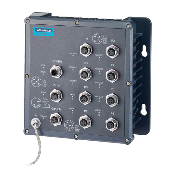
2.3 Front & Bottom View 2.3.1 EKI-6558TI The figures shown below are the front panel and bottom panel of EKI-6558TI. Figure 2.3: EKI-6558TI Front & Bottom Panels EKI-6558TI_EKI-6559TMI_Manual_ed2... -
Page 25: Eki-6559Tmi
2.3.2 EKI-6559TMI The figures shown below are the front panel and bottom panel of EKI-6559TMI. Figure 2.4: EKI-6559TMI Front & Bottom Panels Chapter2... -
Page 26: Mounting
2.4 Mounting 2.4.1 Wall mounting Besides desktop installation, the industrial switch is specially designed to hang on the wall for space-constrained environments. The drawing below illustrates the wall- mounting installation to hang the switch on the wall via four mounting holes on the sides. -
Page 27: Fast Ethernet Ports
Fast Ethernet Ports The M-12 D-coded Fast Ethernet ports are auto-sensing for 10Base-T or 100Base-TX connections. Auto MDI/MDI-X means that you can connect to another switch or workstation without changing straight-through or cross-over cabling. M12 D-coded Connector Pin Assignments Figure 2.6: M12 D-coded Fast Ethernet Connector Pin Number Assignments Note... -
Page 28: Wiring The Power Inputs
2.6 Wiring the Power Inputs Connect the positive and negative wires to PWR1 (V1+, V1-) and PWR2 (V2+, V2-) as the power pin assignments shown below. Figure 2.7: Power1 & Power 2 Contacts 2.7 Wiring the P-Fail Alarm Contacts The P-Fail alarm relay is provided to signal critical error conditions that may occur on the switch. -
Page 29: Hardware Installation
2.8 Hardware Installation This section is intended to guide users on how to install the IP-67 MANAGED INDUSTRIAL ETHERNET SWITCH with the installation points attending to it. Installation Steps 1. Unpack the industrial switch 2. To hang the industrial switch on the wall, please refer to the Wall Mounting section. 3. -
Page 30: X-Ring Application
2.9 X-Ring Application The industrial switch supports the X-Ring protocol that can help the network system recover from network connection failure within 20ms or less, and make the network system more reliable. The X-Ring algorithm is similar to Spanning Tree Protocol (STP) and Rapid STP (RSTP) algorithm but its recovery time is less than STP/RSTP. -
Page 31: Coupling-Ring Application
2.10 Coupling-Ring Application In the network, it may have more than one X-Ring group. Using the coupling ring function can connect each X-Ring for redundant backup. It can ensure the transmissions between two ring groups not to fail. The following figure is a sample of coupling ring application. -
Page 32: Dual Homing Application
2.11 Dual Homing Application The Dual Homing function is to prevent the connection loss from between X-Ring group and upper level/core switch. Assign two ports to be the Dual Homing port that is the backup port in the X-Ring group. The Dual Homing function only works when the X- Ring function is active. -
Page 33: Chapter 3 Configuration
Configuration Sections include: RS-232 Console Web Browser Chapter3... -
Page 34: Rs-232 Console
Chapter 3 Configuration The IP-67 MANAGED INDUSTRIAL ETHERNET SWITCH can be configured in two ways: via RS-232 Console or a web browser. 3.1 RS-232 Console The supplied cable which one end is RS-232 connector and the other end is M12, 8-pole A-coded, Male connector. - Page 35 From the Windows desktop, click ‘Start/Programs/Accessories/Communications/HyperTerminal’ to open the Hyper Terminal program. Figure 3.1: Open Hyper Terminal Select the appropriate COM port, and set the parameter as Fig.3.2 (9600 for Baud Rate, 8 for Data Bits, None for Parity, 1 for Stop Bits, and None for Flow Control). Figure 3.2: COM Port Properties Setting Chapter3...
- Page 36 Press Enter for login screen (If you can not find the login screen, press Enter one more time). The default user name and password are both “admin”. Key in user name and password to enter the command line interface. Figure 3.3: Login Screen: RS-232 Configuration After you have logged in to the system, you will see a command prompt.
-
Page 37: Commands Level
The following table lists the CLI commands and description. 3.1.1 Commands Level Table 3.2: Command Level Modes Access Method Prompt Exit Method About This Model Begin a session with Enter logout or quit. The user commands available your switch. at the user level are a subset of those available at the User EXEC switch>... -
Page 38: System Commands Set
3.1.3 System Commands Set Table 3.4: System Commands Set Commands Level Description Example Show switch configuration switch>show config show config Show console information switch#show terminal show terminal Save user configuration into switch#write memory write memory permanent memory (flash rom) Configure system name switch(config)#system name xxx system name [System Name]... -
Page 39: Port Commands Set
Disable IP security function switch(config)#no security no security Disable IP security of HTTP server switch(config)#no security http no security http Disable IP security of telnet server switch(config)#no security telnet no security telnet 3.1.4 Port Commands Set Table 3.5: Port Commands Set Commands Level Description... -
Page 40: Trunk Commands Set
show interface configuration status switch(config)#interface fastEthernet 2 show interface configuration switch(config-if)#show interface configuration show interface actual status switch(config)#interface fastEthernet 2 show interface status switch(config-if)#show interface status show interface statistic counter switch(config)#interface fastEthernet 2 show interface accounting switch(config-if)#show interface accounting Clear interface accounting switch(config)#interface fastEthernet 2 no accounting information... -
Page 41: Spanning Tree Commands Set
No VLAN Switch(vlan)#no vlan no vlan Ported based VLAN configuration Add new port based VALN switch(vlan)#vlan port-based grpname test grpid vlan port-based grpname [Group Name] 2 port 2-4 grpid [GroupID] switch(vlan)#vlan port-based grpname test grpid port 2 port 2,3,4 [PortNumbers] [GroupID] Show VLAN information switch(vlan)#show vlan 23... -
Page 42: Qos Commands Set
change the interval between messages the spanning tree receives from the root switch. If a switch does not receive a bridge protocol data unit (BPDU) message from the root switch within this interval, it recomputed the Spanning Tree Protocol (STP) topology. -
Page 43: Igmp Commands Set
Disable QoS function switch(config)#no qos no qos 3.1.9 IGMP Commands Set Table 3.10: QOS Commands Set Commands Level Description Example Enable IGMP snooping function switch(config)#igmp enable igmp enable Set IGMP query to auto mode switch(config)#Igmp-query auto Igmp-query auto Set IGMP query to force mode switch(config)#Igmp-query enable Igmp-query enable Set unregister stream flooding... - Page 44 Table 3.12: SNMP Commands Set Commands Level Description Example Set SNMP agent system name switch(config)#snmp system-name l2switch snmp system-name [System Name] Set SNMP agent system location switch(config)#snmp system-location lab snmp system-location [System Location] Set SNMP agent system contact switch(config)#snmp system-contact where snmp system-contact [System Contact] Select the agent mode of SNMP...
-
Page 45: Port Mirroring Commands Set
3.1.12 Port Mirroring Commands Set Table 3.13: Port Mirroring Commands Set Commands Level Description Example Set RX destination port of monitor switch(config)#monitor rx monitor rx function Set TX destination port of monitor switch(config)#monitor tx monitor tx function Show port monitor information switch#show monitor show monitor Configure source port of monitor... -
Page 46: Tftp Commands Set
global configuration command to set the reauth period. Use the 802.1x port state interface switch(config)#interface fastethernet 3 8021x portstate configuration command to set the switch(config-if)#8021x portstate accept [disable | reject | accept | authorize] state of the selected port. Displays a summary of the 802.1x switch>show 8021x show 8021x properties and also the port sates. -
Page 47: Sntp Commands Set
Show event selection switch#show event show event Disable cold start event type switch(config)#no event device-cold-start no event device-cold-start Disable Authentication failure switch(config)#no event authentication-failure no event authentication-failure event type Disable X - ring topology changed switch(config)#no event X-ring-topology-change no event X-ring-topology-change event type Disable port event for system log switch(config)#interface fastethernet 3... -
Page 48: Lldp Command Set
Configure Dual Homing Port switch(config)#ring homingport 3 ring homingport [Dual Homing Port] Show the information of X - Ring switch#show ring show ring Disable X-ring switch(config)#no ring no ring Disable ring master switch(config)#no ring master no ring master Disable couple ring switch(config)#no ring couplering no ring couplering Disable dual homing... -
Page 49: Web Browser
3.2 Web Browser IP-67 MANAGED INDUSTRIAL ETHERNET SWITCH provides a convenient configuring way via web browser. You can follow the steps below to access IP-67 MANAGED INDUSTRIAL ETHERNET SWITCH. IP-67 MANAGED INDUSTRIAL ETHERNET SWITCH’s default IP is 192.168.1.1. Make sure your host PC and IP-67 MANAGED INDUSTRIAL ETHERNET SWITCH are on the same logical sub-network. - Page 50 The default user name and password are both admin, fill in the user name and password then press OK to enter the configuration. You can change the password in the system setting. In the main page, you can find the tree menu structure of the IP-67 MANAGED INDUSTRIAL ETHERNET SWITCH in the left side.
- Page 51 3.2.1 System System Information Assign the system name, location and view the system information • System Name: Assign the name of the switch. The maximum length is 64 bytes. • System Description: Displays the description of switch. Read only cannot be modified. •...
- Page 52 IP Configuration User can configure the IP Settings and DHCP client function here. • DHCP Client: Enable or disable the DHCP client function. When DHCP client function is enabled, the industrial switch will be assigned an IP address from the network DHCP server. The default IP address will be replaced by the assigned IP address on DHCP server.
- Page 53 DHCP Server – System configuration DHCP is the abbreviation of Dynamic Host Configuration Protocol that is a protocol for assigning dynamic IP addresses to devices on a network. With dynamic addressing, a device can have a different IP address every time it connects to the network. In some systems, the device's IP address can even change while it is still connected.
- Page 54 Figure 3.11: DHCP Server – Client Entries DHCP Server - Port and IP Bindings Assign the dynamic IP address to the port. When the device is connecting to the port and asks for IP assigning, the system will assign the IP address that has been assigned before to the connected device. Figure 3.12: DHCP Server –...
- Page 55 TFTP - Update Firmware Trivial File Transfer Protocol (TFTP) is a very simple file transfer protocol, with the functionality of a very basic form of FTP. It provides the functions to allow the user to update the switch firmware. Before updating, make sure you have your TFTP server ready and the firmware image is on the TFTP server.
- Page 56 TFTP - Backup Configuration You can save current Flash ROM value from the switch to TFTP server for restoring later. • TFTP Server IP Address: Fill in the TFTP server IP • Backup File Name: Fill in the file name •...
- Page 57 System Event Log – Syslog Configuration Configure the system event mode to collect system log. • Syslog Client Mode: Select the system log mode—Client Only, Server Only, or Both. • System Log Server IP Address: Assign the system log server IP. •...
- Page 58 System Event Log - SMTP Configuration You can set up the mail server IP, mail account, password, and forwarded email account for receiving the event alert. • Email Alert: Enable or disable the email alert function. • SMTP Server IP: Set up the mail server IP address (when Email Alert enabled, this function will then be available).
- Page 59 System Event Log - Event Configuration When the Syslog/SMTP checkbox is ticked, the event log will be sent to system log server/SMTP server. Also, per port log (link up, link down, and both) events can be sent to the system log server/SMTP server with the respective checkbox ticked.
- Page 60 Fault Relay Alarm • Power Failure: Tick the checkbox to enable the function of lighting up the FAULT LED on the panel when power fails. • Port Link Down/Broken: Tick the checkbox to enable the function of lighting up FAULT LED on the panel when ports’...
- Page 61 SNTP Configuration You can configure the SNTP (Simple Network Time Protocol) settings which allow you to synchronize switch clocks with an Internet time server. • SNTP Client: Enable/disable SNTP function to get the time from the SNTP server. • Daylight Saving Time: Enable/disable daylight saving time function. When daylight saving time is enabled, you need to configure the daylight saving time period.
- Page 62 ZP5 - USSR Zone 4 +5 hours 5 pm ZP6 - USSR Zone 5 +6 hours 6 pm WAST - West Australian Standard +7 hours 7 pm CCT - China Coast, USSR Zone 7 +8 hours 8 pm JST - Japan Standard, USSR Zone 8 +9 hours 9 pm EAST - East Australian Standard GST...
- Page 63 IP Security IP security function allows the user to assign 10 specific IP addresses that have permission to access the switch through the web browser for the securing switch management. • IP Security Mode: When this option is in Enable mode, the Enable HTTP Server and Enable Telnet Server checkboxes will then be available.
- Page 64 User Authentication Change web management login user name and password for the management security issue. • User name: Key in the new user name (The default is “admin”). • Password: Key in the new password (The default is “admin”). • Confirm password: Re-type the new password. •...
- Page 65 3.2.2 Port Port setting includes Port Statistics, Port Control, Port Trunk, Port Mirroring, and Rate Limiting. The user can use this interface to set the parameters and control the packet flow among the ports. Port Statistics The following information provides the current port statistic information. •...
- Page 66 Port Control In Port Control, you can pull down the selection items to set the parameters of each port to control the transmitting/receiving packets. • Port: Select the port that you want to configure. • State: Current port status. The port can be set to disable or enable mode. If the port state is set as ‘Disable’, it will not receive or transmit any packet.
- Page 67 Port Trunk The Link Aggregation Control Protocol (LACP) provides a standardized means for exchanging information between Partner Systems on a link to allow their Link Aggregation Control instances to reach agreement on the identity of the Link Aggregation Group to which the link belongs, move the link to that Link Aggregation Group, and enable its transmission and reception functions in an orderly manner.
- Page 68 Aggregator Information When you have set up the aggregator setting with LACP disabled, you will see the local static trunk group information as below. Figure 3.26: 2 work ports with LACP disabled Figure 3.27: Static trunking group of 2 ports EKI-6558TI_EKI-6559TMI_Manual_ed2...
- Page 69 When you have set up the aggregator setting of two interconnected switches with LACP enabled, you will see the respective LACP trunk group information as below. Figure 3.28: Aggregator Information State Activity Having set up the LACP aggregator on the tab of Aggregator Setting, you can configure the state activity for the members of the LACP trunk group.
- Page 70 Port Mirroring The Port mirroring is a method for monitoring traffic in switched networks. Traffic through ports can be monitored by one specific port which means traffic goes in or out monitored (source) ports will be duplicated into mirroring (destination) port. •...
- Page 71 Rate Limiting Here you can set up every port’s frame limitation type and bandwidth rate. • Ingress Limit Frame type: Select the frame type you want to filter. The frame types have 4 options for selecting: All, Broadcast/Multicast/Flooded Unicast, Broadcast/Multicast, and Broadcast only. The four frame type options are for ingress frames limitation.
- Page 72 3.2.3 Protocol The user can set the layer 2 protocol setting via this interface. VLAN configuration A Virtual LAN (VLAN) is a logical network grouping that limits the broadcast domain, which would allow you to isolate network traffic, so only the members of the same VLAN will receive traffic from the ones of the same VLAN.
- Page 73 Figure 3.33: Port based mode • Pull down the selection item and focus on Port Based then press Apply to set the VLAN Operation Mode in Port Based mode. • Click to add a new VLAN group. Figure 3.34: Port based mode-Add interface •...
- Page 74 Figure 3.35: Port Based Edit/Delete interface • Use Delete to delete the VLAN. • Use to modify group name, VLAN ID, or add/remove the members of the existing VLAN group. Edit Note Remember to execute the “Save Configuration” action, otherwise the new configuration will lose when switch power off.
- Page 75 802.1Q VLAN Tagged-based VLAN is an IEEE 802.1Q specification standard. Therefore, it is possible to create a VLAN across devices from different switch venders. IEEE 802.1Q VLAN uses a technique to insert a “tag” into the Ethernet frames. Tag contains a VLAN Identifier (VID) that indicates the VLAN numbers. You can create Tag-based VLAN, and enable or disable GVRP protocol.
- Page 76 Figure 3.36: 802.1Q VLAN Configuration Group Configuration Edit the existing VLAN Group. • Select the VLAN group in the table list. • Click Edit Figure 3.37: Edit Group Configuration interface EKI-6558TI_EKI-6559TMI_Manual_ed2...
- Page 77 • You can Change the VLAN group name and VLAN ID. Figure 3.38: 802.1Q Group Configuration-Edit • Click Apply . Chapter3...
- Page 78 Rapid Spanning Tree The Rapid Spanning Tree Protocol (RSTP) is an evolution of the Spanning Tree Protocol and provides for faster spanning tree convergence after a topology change. The system also supports STP and the system will auto-detect the connected device that is running STP or RSTP protocol. RSTP - System Configuration •...
- Page 79 Here you can configure the path cost and priority of each port. • Select the port in the port column field. • Path Cost: The cost of the path to the other bridge from this transmitting bridge at the specified port. Enter a number 1 through 200,000,000.
- Page 80 SNMP Configuration Simple Network Management Protocol (SNMP) is the protocol developed to manage nodes (servers, workstations, routers, switches and hubs etc.) on an IP network. SNMP enables network administrators to manage network performance, find and solve network problems, and plan for network growth. Network management systems learn of problems by receiving traps or change notices from network devices implementing SNMP.
- Page 81 • IP Address: Enter the IP address of the trap manager. • Community: Enter the community string. • Trap Version: Select the SNMP trap version type—v1 or v2c. • Click Add . • To remove the community string, select the community string listed in the current managers field and click Remove .
- Page 82 Figure 3.43: SNMP V3 Configuration interface Group Table Configure SNMP v3 group table. • Security Name (User ID): Assign the user name that you have set up in user table. • Group Name: Set up the group name. • Click Add to add context name. •...
- Page 83 Access Table Configure SNMP v3 access table. • Context Prefix: Set up the context name. • Group Name: Set up the group. • Security Level: Set up the access level. • Context Match Rule: Select the context match rule. • Read View Name: Set up the read view. •...
- Page 84 QoS Configuration Here you can configure Qos policy and priority setting, per port priority setting, COS and TOS setting. QoS Policy and Priority Type • Qos Policy: Select the QoS policy rule. Use an 8,4,2,1 weighted fair queuing scheme: The switch will follow 8:4:2:1 rate to process priority queue from High to lowest queue.
- Page 85 Figure 3.44: QoS Configuration interface Port Base Priority Configure the priority level for each port. With the drop-down selection item of Priority Type above being selected as Port-based, this control item will then be available to set the queuing policy for each port. •...
- Page 86 COS Configuration Set up the COS priority level. With the drop-down selection item of Priority Type above being selected as COS only/COS first, this control item will then be available to set the queuing policy for each port. • COS priority: Set up the COS priority level 0~7—High, Middle, Low, Lowest. •...
- Page 87 IGMP Configuration The Internet Group Management Protocol (IGMP) is an internal protocol of the Internet Protocol (IP) suite. IP manages multicast traffic by using switches, routers, and hosts that support IGMP. Enabling IGMP allows the ports to detect IGMP queries, report packets, and manage IP multicast traffic through the switch.
- Page 88 X-Ring X-Ring provides a faster redundant recovery than Spanning Tree topology. The action is similar to STP or RSTP, but the algorithms between them are not the same. In the X-Ring topology, every switch should be enabled with X-Ring function and two ports should be assigned as the member ports in the ring.
- Page 89 Figure 3.46: X-ring interface Note When the X-Ring function enable, user must disable the RSTP. The X-Ring function and RSTP function cannot exist at the same time. Remember to execute the “Save Configuration” action, otherwise the new configuration will lose when switch power off. Chapter3...
- Page 90 LLDP Configuration LLDP (Link Layer Discovery Protocol) function allows the switch to advertise its information to other nodes on the network and store the information it discovers. • LLDP Protocol: Disable or enable LLDP function. • LLDP Interval: Set the interval of learning the information time in second. •...
- Page 91 3.2.4 Security In this section, you can configure 802.1x and MAC address table. 802.1X/Radius Configuration 802.1x is an IEEE authentication specification which prevents the client from connecting to a wireless access point or wired switch until it provides authority, like the user name and password that are verified by an authentication server (such as RADIUS server).
- Page 92 Figure 3.49: 802.1x/Radius - Port Configuration interface 802.1X/Radius - Misc Configuration • Quiet Period: Set the period which the port doesn’t try to acquire a supplicant. • TX Period: Set the period the port waits for retransmit next EAPOL PDU during an authentication session.
- Page 93 MAC Address Table Use the MAC address table to ensure the port security. You can add a static MAC address; it remains in the switch's address table, regardless of whether the device is physically connected to the switch. This saves the switch from having to re-learn a device's MAC address when the disconnected or powered-off device is active on the network again.
- Page 94 Figure 3.52: MAC Filtering interface • MAC Address: Enter the MAC address that you want to filter. • Click Add . • If you want to delete the MAC address from filtering table, select the MAC address and click Delete . MAC Address Table - All MAC Addresses You can view the port that connected device’s MAC address and the related devices’...
- Page 95 MAC Address Table—Multicast Filtering Multicasts are similar to broadcasts, they are sent to all end stations on a LAN or VLAN. Multicast filtering is the system by which end stations only receive multicast traffic if they register to join specific multicast groups.
- Page 96 Factory Default Reset switch to default configuration. Click Reset to reset all configurations to the default value. Figure 3.55: Factory Default interface Save Configuration Save all configurations that you have made in the system. To ensure the all configuration will be saved, click Save to save the all configuration to the flash memory.
- Page 97 Troubleshooting...
- Page 98 Chapter 4 Troubleshooting Verify that you are using the right power cord/adapter. Don’t use the power adaptor with DC output voltage higher than the input voltage of the device, or the device will burn down. Select the proper UTP cable to construct the user network. Use unshielded twisted-pair (UTP) or shield twisted-pair (STP) cable for RJ-45 connections: 100Ω...
- Page 99 Mouser Electronics Authorized Distributor Click to View Pricing, Inventory, Delivery & Lifecycle Information: Advantech EKI-6558TI-AE EKI-6559TMI-AE...
Need help?
Do you have a question about the EKI-6558TI and is the answer not in the manual?
Questions and answers