Table of Contents
Advertisement
User Manual
P/N: 2016-EKI-7710-01
Version: Edition 1, 2016/02
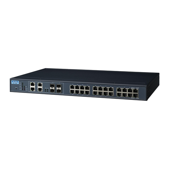
EKI-7428G Series
24G+4G Combo port L2 Managed
Switch
EK I-7
42 8G
SY S
28
PW 1
26
PW 2
Re set
R.M .
28
P-F AIL
26
Ri ng Fa
LO OP
il
De tec tio
Te mp
n
LIN K / AC
T
27
25
27
25
EK I-7 42
8G -4C
I
SY S
28
PW 1
26
PW 2
Re set
R.M .
P-F AIL
28
Ri ng Fa
26
LO OP
il
De tec tio
Te mp
n
LIN K / AC
T
27
25
27
25
24
22
20
18
16
14
12
10
8
6
23
21
4
PoE
19
2
LIN K/A
17
15
13
11
9
7
5
3
PoE
1
LIN K/A
24
22
20
18
16
14
12
10
8
6
23
4
21
PoE
2
19
LIN K/A
17
15
13
11
9
7
5
3
PoE
1
LIN K/A
CT
CT
CT
CT
Advertisement
Table of Contents

Related Manuals for Advantech EKI-7428G Series


Summary of Contents for Advantech EKI-7428G Series
-
Page 1: User Manual
User Manual EKI-7428G Series 24G+4G Combo port L2 Managed Switch EK I-7 42 8G SY S PW 1 PW 2 Re set R.M . P-F AIL Ri ng Fa LO OP De tec tio Te mp LIN K / AC... -
Page 2: Table Of Contents
Content Chapter 1 Product Overview 1.1. Specifications ..........1 1.2. - Page 3 3.1.3 Administrative Interface Access..........21 3.1.4 Using the Graphical (Web) Interface ........22 3.1.5 Configuring the Switch for Network Access ......22 3.1.6 Configuring the Ethernet Ports ..........23 3.2. Command Line Interface Configuration......23 3.2.1 Introduction to Command-Line Interface (CLI) ......
- Page 4 4.5.7 802.3az EEE................58 4.5.8 Multicast................... 59 4.5.9 Jumbo Frame................65 4.5.10 Spanning Tree ................. 66 4.5.11 X-Ring Elite................73 4.5.12 X-Ring Pro ................75 4.5.13 Loopback Detection ..............77 4.6. MAC Address Table ........79 4.6.1 Static MAC................
- Page 5 4.10.4 System Log................135 4.10.5 DDM..................138 4.11. Tools ..........140 4.11.1 IXM ..................
- Page 6 We recommend the use of shielded cables. This kind of cable is available from Advantech. Please contact your local supplier for ordering information. This product has passed the CE test for environmental specifications. Test conditions for passing included the equipment being operated within an industrial enclosure.
- Page 7 1 ALY 20 LN 26 RUEIGUANG RD NEIHU DISTRICT TAIPEI 114 TAIWAN Advantech warrants to you, the original purchaser, that each of its products will be free from defects in materials and workmanship for two years from the date of purchase.
- Page 8 Note signs are used to provide additional information for the device or settings. Copyright Copyright © 2016 Advantech Inc. All rights reserved. No part of this publication may be reproduced, adapted, stored in a retrieval system, translated into any language, or transmit- ted in any form or by any means without the written permission of the manufacturer.
-
Page 9: About This Manual
The exact wording of any error messages About This Manual This user manual is intended to guide professional installers in installing and configuring the 24G+4G Combo port L2 Managed Switch. It includes technical specifications, software util- ity introduciton, as we as procedures for the use of the software utility to self-manage the devices. -
Page 11: Product Overview
Product Overview Chapter 1... -
Page 12: Specifications
RODUCT VERVIEW 1.1. Specifications Table 1-1. Specifications Specifications Description Interface I/O Port 24 x 10/100/1000BaseT(X) + 4 x 10/100/1000Base-T(X) or 4 x 100/1000Base-X SFP Port Power Connector 4-pin removable screw terminal (power & relay) Physical Enclosure Metal Shell Protection Class IP30 Installation Rack mounting... - Page 13 RODUCT VERVIEW Table 1-1. Specifications (Continued) Specifications Description Certifications Safety IEC EN60950, EN61010 CE, FCC EN55022 Class A EN 61000-4-2 (ESD) Level 3 EN 61000-4-3 (RS) Level 3; EN 61000-4-4 (EFT) Level 3 EN 61000-4-5 (Surge) Level 3; ...
-
Page 14: Hardware Views
RODUCT VERVIEW 1.2. Hardware Views 1.2.1 Front View LINK/ACT EKI-7428G R.M. LINK / ACT P-FAIL Ring Fail Reset LOOP Temp Detection LINK/ACT Figure 1-1. Front View Table 1-2. Front View Item Description Reset button Button allows for system soft reset or factory default reset. System LED panel See “System LED Panel”... - Page 15 RODUCT VERVIEW System LED Panel R.M. LINK / ACT P-FAIL Ring Fail LOOP Temp Detection Figure 1-2. System LED Panel Table 1-3. System LED Panel LED Name LED Color Description Solid green System is operating normally. System is powered down / system crash / operation initiating.
-
Page 16: Rear View
RODUCT VERVIEW Table 1-3. System LED Panel (Continued) LED Name LED Color Description LNK/ACT Solid green Current link speed is 1000M. Blink green Packet transmit and receive. No link. Solid amber Current link speed is 100/10M. Blink amber Packet transmit and receive. No link. -
Page 17: Dimensions
RODUCT VERVIEW 1.3. Dimensions Figure 1-4. EKI-7428G-4CPI Dimensions... -
Page 18: Packing List
RODUCT VERVIEW Figure 1-5. EKI-7428G-4CI Dimensions 1.4. Packing List The product package you have received should contain the following items. If any of them are not included or damaged, please contact your local vendor for support. 1 x Industrial Ethernet Switch ... -
Page 19: Switch Installation
Switch Installation Chapter 2... -
Page 20: Warnings
WITCH NSTALLATION 2.1. Warnings Warning: Before working on equipment that is connected to power lines, remove any jewelry (including rings, necklaces, and watches). Metal objects can heat up when connected to power and ground, which can cause serious burns or weld the metal object to the terminals. Exposure to chemicals can degrade the sealing properties of materials used in the sealed relay device. -
Page 21: Installation Guidelines
WITCH NSTALLATION If the switch is to be installed in a hazardous location, ensure that the DC power source is located away from the vicinity of the switch. The installation of the equipment must comply with all national and local electrical codes. -
Page 22: Connecting Hardware
WITCH NSTALLATION ensuring electromagnetic compatibility in other environments due to conducted as well as radiated disturbance. This equipment is supplied as open-type equipment. It must be mounted within an enclo- sure that is suitably designed for those specific environmental conditions that will be present and appropriately designed to prevent personal injury resulting from accessibility to live parts. -
Page 23: Installing And Removing Sfp Modules
The Gigabit Ethernet ports on the switch are 100/1000Base SFP Fiber ports, which require using the 100M or 1G mini-GBIC fiber transceivers to work properly. Advantech provides completed transceiver models for different distance requirement. The concept behind the LC port and cable is quite straight forward. Suppose that you are connecting devices I and II;... -
Page 24: Installing Sfp Modules
WITCH NSTALLATION 2.6.1 Installing SFP Modules To connect the fiber transceiver and LC cable, use the following guidelines: 1. Remove the dust plug from the fiber optic slot chosen for the SFP transceiver. Figure 2-3. Removing the Dust Plug from an SFP Slot Do not remove the dust plug from the SFP slot if you are not installing the trans- ceiver at this time. -
Page 25: Removing Sfp Modules
WITCH NSTALLATION 6. Remove the protective plug from the SFP transceiver. Do not remove the dust plug from the transceiver if you are not installing the fiber optic cable at this time. The dust plug protects hardware from dust contamination. 7. -
Page 26: Connecting The Switch To Ethernet Ports
WITCH NSTALLATION 3. Hold the handle on the transceiver and pull the transceiver out of the slot. Handle Figure 2-7. Removing an SFP Transceiver Replace the dust plug on the slot if you are not installing a transceiver. The dust plug protects hardware from dust contamination. -
Page 27: Connecting The Switch To Console Port
WITCH NSTALLATION 2.8. Connecting the Switch to Console Port The industrial switch supports a secondary means of management. By connecting the RJ45 to RS232 serial cable between a COM port on your PC (9-pin D-sub female) and the switch’s RJ45 (RJ45) port, a wired connection for management can be established. To terminal or PC To console port Figure 2-9. -
Page 28: Power Supply Installation
(pane) (pane) One DC Supply Dual DC Supplies Figure 2-12. Power Wiring for EKI-7428G Series 2.9.2 Considerations Take into consideration the following guidelines before wiring the device: The Terminal Block (CN1) is suitable for 12-24 AWG (3.31 - 0.205 mm ). -
Page 29: Grounding The Device
WITCH NSTALLATION Make sure to separate input and output wiring. Label all wiring and cabling to the various devices for more effective management and servicing. Routing communications and power wiring through the same conduit may cause signal interference. To avoid interference and signal degradation, route power and communications wires through separate conduits. -
Page 30: Wiring A Relay Contact
WITCH NSTALLATION By connecting the ground terminal by drain wire to earth ground the switch and chassis can be ground. Before applying power to the grounded switch, it is advisable to use a volt meter to ensure there is no voltage difference between the power supply’s negative output terminal and the grounding point on the switch. -
Page 31: Reset Button
WITCH NSTALLATION Make sure the power is not connected to the switch or the power converter before proceed- ing. 1. Insert a small flat-bladed screwdriver in the V1+/V1- wire-clamp screws, and loosen the screws. 2. Insert the negative/positive DC wires into the V+/V- terminals of PW1. If setting up power redundancy, connect PW2 in the same manner. - Page 32 WITCH NSTALLATION...
-
Page 33: Configuration Utility
Configuration Utility Chapter 3... -
Page 34: First Time Setup
ONFIGURATION TILITY 3.1. First Time Setup 3.1.1 Overview The Industrial Ethernet Managed Switch is a configurable device that facilitates the intercon- nection of Ethernet devices on an Ethernet network. This includes computers, operator interfaces, I/O, controllers, RTUs, PLCs, other switches/hubs or any device that supports the standard IEEE 802.3 protocol. -
Page 35: Using The Graphical (Web) Interface
ONFIGURATION TILITY 3.1.4 Using the Graphical (Web) Interface The graphical interface is provided via a web server in the switch and can be accessed via a web browser such as Opera, Mozilla, or Internet Explorer. JavaScript must be supported and enabled in your browser for the graphical inter- face to work correctly. -
Page 36: Configuring The Ethernet Ports
ONFIGURATION TILITY NTP Server: The IP address or domain name of an NTP (Network Time Protocol) server from which the switch may retrieve the current time at startup. Please note that using a domain name requires that at least one domain name server be configured. 3.1.6 Configuring the Ethernet Ports The switch comes with default port settings that should allow you to connect to the Ethernet Ports with out any necessary configuration. -
Page 37: Accessing The Cli
ONFIGURATION TILITY such as Telnet, FTP, and SMTP. After each command is entered and processed, the switch will issue a reply that consists of a numeric status code and a human-readable explanation of the status. The general format of commands is: section parameter [value] where: section is used to group parameters. -
Page 38: System Login
ONFIGURATION TILITY Default gateway: 192.168.1.254 User name: admin Password: admin 3.3.2 System Login Once the switch is installed and connected, power on the switch. The following information guides you through the logging in process. 1. Launch your web browser on the PC. 2. -
Page 39: Managing Switch
Managing Switch Chapter 4... -
Page 40: Log In
ANAGING WITCH 4.1. Log In To access the login window, connect the device to the network, see “Connecting the Switch to Ethernet Ports” on page 13. Once the switch is installed and connected, power on the switch see the following procedures to log into your switch. When the switch is first installed, the default network configuration is set to DHCP enabled. -
Page 41: Recommended Practices
ANAGING WITCH 4.2. Recommended Practices One of the easiest things to do to help increase the security posture of the network infrastructure is to implement a policy and standard for secure management. This practice is an easy way to maintain a healthy and secure network. After you have performed the basic configurations on your switches, the following is a recommendation which is considered best practice policy. -
Page 42: Monitoring
ANAGING WITCH 4.3. Monitoring 4.3.1 Device Information The Device Information menu lists information, such as: System Name, System Location, MAC Address, Firmware version, and more, pertaining to the system. The information is for review only. To modify the device information, see the respective item within the user interface. - Page 43 ANAGING WITCH Table 4-1. Monitoring > Device Information (Continued) Item Description Subnet Mask Displays the assigned subnet mask of the switch. Gateway Displays the assigned gateway of the switch. Loader Version Displays the current loader version of the switch. Loader Date Displays the current loader build date of the switch.
-
Page 44: Logging Message
ANAGING WITCH 4.3.2 Logging Message The Logging Message Filter page allows you to enable the display of logging message filter. To access this page, click Monitoring > Logging Message. Figure 4-4. Monitoring > Logging Message The following table describes the items in the previous figure. Table 4-2. -
Page 45: Port Monitoring
ANAGING WITCH The ensuing table for Logging Information table settings are informational only: Target, Severity and Category. The ensuing table for Logging Message table settings are informational only: No., Time Stamp, Category, Severity and Message. 4.3.3 Port Monitoring Port Network Monitor is a bandwidth and network monitoring tool for the purpose of capturing network traffic and measuring of network throughput. -
Page 46: Link Aggregation
ANAGING WITCH Port Utilization To access this page, click Monitoring > Port Monitoring > Port Utilization. Figure 4-6. Monitoring > Port Monitoring > Port Utilization The following table describes the items in the previous figure. Table 4-4. Monitoring > Port Monitoring > Port Utilization Item Description Refresh period... -
Page 47: Lldp Statistics
ANAGING WITCH 4.3.5 LLDP Statistics The LLDP Statistics page displays the LLDP statistics. To access this page, click Monitoring > LLDP Statistics. Figure 4-7. Monitoring > LLDP Statistics The following table describes the items in the previous figure. Table 4-5. Monitoring > LLDP Statistics Item Description Clear... -
Page 48: Igmp Statistics
ANAGING WITCH 4.3.6 IGMP Statistics The IGMP Statistics function displays statistical package information for IP multicasting. To access this page, click Monitoring > IGMP Statistics. Figure 4-8. Monitoring > IGMP Statistics The following table describes the items in the previous figure. Table 4-6. -
Page 49: System
ANAGING WITCH 4.4. System 4.4.1 IP Settings The IP Settings menu allows you to select a static or DHCP network configuration. The Static displays the configurable settings for the static option. To access this page, click System > IP Settings. Figure 4-9. -
Page 50: Dhcp Client Option 82
ANAGING WITCH 4.4.2 DHCP Client Option 82 The DHCP Client Option 82 configurable Circuit ID and Remote ID feature enhances validation security by allowing you to select naming choices suboptions. You can select a switch-configured hostname or specify an ASCII test string for the remote ID. You can also configure an ASCII text string to override the circuit ID. -
Page 51: Dhcp Auto Provision
ANAGING WITCH Table 4-8. System > DHCP Client Option 82 (Continued) Item Description Remote ID Hex Enter the remote hex string of the corresponding class. Remote ID User- Enter the remote user definition of the corresponding class. Define Apply Click Apply to save the values and update the screen. The ensuing table for DHCP Client Option 82 Information table settings are informational only: Status, Circuit ID Format, Circuit ID String, Circuit ID Hex, Circuit ID User-Define, Remote ID Format, Remote ID String, Remote ID Hex and Remote ID User-Define. -
Page 52: Ipv6 Settings
ANAGING WITCH 4.4.4 IPv6 Settings To access this page, click System > IPv6 Settings. Figure 4-12. System > IPv6 Settings The following table describes the items in the previous figure. Table 4-10. System > IPv6 Settings Item Description Auto Configuration Select the radio button to enable or disable the IPv6. -
Page 53: Management Vlan
ANAGING WITCH 4.4.5 Management VLAN By default the VLAN is the management VLAN providing communication with the switch management interface. To access this page, click System > Management VLAN. Figure 4-13. System > Management VLAN The following table describes the items in the previous figure. Table 4-11. -
Page 54: System Time
ANAGING WITCH 4.4.6 System Time To access this page, click System > System Time. Figure 4-14. System > System Time... - Page 55 ANAGING WITCH The following table describes the items in the previous figure. Table 4-12. System > System Time Item Description Enable SNTP Click the radio button to enable or disable the SNTP. SNTP/NTP Server Enter the address of the SNTP server. This is a text string of up to 64 Address characters containing the encoded unicast IP address or hostname of a SNTP server.
-
Page 56: L2 Switching
ANAGING WITCH 4.5. L2 Switching 4.5.1 Port Configuration Port Configuration describes how to use the user interface to configure LAN ports on the switch. To access this page, click L2 Switching > Port Configuration. Figure 4-15. L2 Switching > Port Configuration The following table describes the items in the previous figure. -
Page 57: Port Mirror
ANAGING WITCH 4.5.2 Port Mirror Port mirroring function allows the sending of a copy of network packets seen on one switch port to a network monitoring connection on another switch port. Port mirroring can be used to analyze and debug data or diagnose errors on a network or to mirror either inbound or outbound traffic (or both). -
Page 58: Link Aggregation
ANAGING WITCH 4.5.3 Link Aggregation Link Aggregation is a method for combining multiple network connections in parallel in order to increase throughput beyond the capability of a single connection, and to provide redundancy in case one of the links should fail. Load Balance The Load Balancing page allows you to select between a MAC Address or IP/MAC Address algorithm for the even distribution of IP traffic across two or more links. - Page 59 ANAGING WITCH LAG Management Link aggregation is also known as trunking. It is a feature available on the Ethernet gateway and is used with Layer 2 Bridging. Link aggregation allows for the logical merging of multiple ports into a single link. To access this page, click L2 Switching >...
- Page 60 ANAGING WITCH LAG Port Settings The LAG Port Settings page allows you to enable or disable, set LAG status, speed and flow control functions. In this example we will configure a LAG between the following switches: To access this page, click L2 Switching > Link Aggregation > LAG Port Settings. Figure 4-19.
- Page 61 ANAGING WITCH LACP Priority Settings The LACP Priority Settings page allows you to configure the system priority for LACP. To access this page, click L2 Switching > Link Aggregation > LACP Priority Settings. Figure 4-20. L2 Switching > Link Aggregation > LACP Priority Settings The following table describes the items in the previous figure.
-
Page 62: Lacp Port Settings
ANAGING WITCH LACP Port Settings Link Aggregation Control Protocol (LACP) provides a method to control the bundling of several physical ports together to form a single logical channel. By configuring the LACP function, the switch can negotiate an automatic bundling of links by sending LACP packets to the peer device (also implementing LACP). -
Page 63: Q Vlan
ANAGING WITCH 4.5.4 802.1Q VLAN The 802.1Q VLAN feature allows for a single VLAN to support multiple VLANs. With the 802.1Q feature you can preserve VLAN IDs and segregate different VLAN traffic. The 802.1Q VLAN tag feature encapsulates the 802.1Q VLAN tagging within another 802.1Q VLAN tag. - Page 64 ANAGING WITCH PVID Settings The PVID Settings page allows you to designate a PVID for a selected port, define the accepted type and enable/disable the ingress filtering. To access this page, click L2 Switching > 802.1Q VLAN > PVID Settings. Figure 4-23.
- Page 65 ANAGING WITCH Port to VLAN The Port to VLAN page allows you to add a port to a VLAN and select the related parameters. To access this page, click L2 Switching > 802.1Q VLAN > Port to VLAN. Figure 4-24. L2 Switching > 802.1Q VLAN > Port to VLAN...
-
Page 66: Q-In-Q
ANAGING WITCH The following table describes the items in the previous figure. Table 4-22. L2 Switching > 802.1Q VLAN > Port to VLAN Item Description Port Displays the assigned port to the entry. Interface VLAN Displays the assigned mode to the listed VLAN port. Mode Hybrid: Port hybrid model. - Page 67 ANAGING WITCH Global Settings The Global Settings page allows you to set the outer VLAN Ethertype setting. To access this page, click L2 Switching > Q-in-Q > Global Settings. Figure 4-25. L2 Switching > Q-in-Q > Global Settings The following table describes the items in the previous figure. Table 4-23.
- Page 68 ANAGING WITCH Port Settings The Port Settings page allows you to define the outer PVID and outer mode for a selected port. To access this page, click L2 Switching > Q-in-Q > Port Settings. Figure 4-26. L2 Switching > Q-in-Q > Port Settings The following table describes the items in the previous figure.
-
Page 69: Garp
ANAGING WITCH 4.5.6 GARP The Generic Attribute Registration Protocol (GARP) is a local area network (LAN) protocol. The protocol defines procedures for the registration and de-registration of attributes (network identifiers or addresses) by end stations and switches with each other. GARP Settings To access this page, click L2 Switching >... - Page 70 ANAGING WITCH GVRP Settings The GVRP Settings page allows you to enable or disable the GVRP (GARP VLAN Registration Protocol or Generic VLAN Registration Protocol) protocol which facilitates control of virtual local area networks (VLANs) within a larger network. To access this page, click L2 Switching > GARP > GVRP Settings. Figure 4-28.
-
Page 71: Az Eee
ANAGING WITCH 4.5.7 802.3az EEE The 802.3az Energy Efficient Ethernet (EEE) innovative green feature reduces energy consumption through intelligent functionality: Traffic detection — Energy Efficient Ethernet (EEE) compliance Inactive link detection Inactive link detection function automatically reduces power usage when inactive links or devices are detected. -
Page 72: Multicast
ANAGING WITCH 4.5.8 Multicast Multicast forwarding allows a single packet to be forwarded to multiple destinations. The service is based on L2 switch receiving a single packet addressed to a specific Multicast address. Multicast forwarding creates copies of the packet, and transmits the packets to the relevant ports. - Page 73 ANAGING WITCH IGMP Snooping IGMP Snooping is defined as the process of listening to Internet Group Management Protocol (IGMP) network traffic. IGMP Snooping allows a network switch to listen in on the IGMP conversation between hosts and routers and maintain a map of which links need which IP multicast streams.
- Page 74 ANAGING WITCH To access this page, click L2 Switching > Multicast > IGMP Snooping > IGMP Querier. Figure 4-32. L2 Switching > Multicast > IGMP Snooping > IGMP Querier The following table describes the items in the previous figure. Table 4-30. L2 Switching > Multicast > IGMP Snooping > IGMP Querier Item Description VLAN ID...
- Page 75 ANAGING WITCH Table 4-31. L2 Switching > Multicast > IGMP Snooping > IGMP Static Groups (Continued) Item Description Member Ports Enter the port numbers to associate with the static group. Click Add to add an IGMP group. The ensuing table for IGMP Static Groups Status settings are informational only: VLAN ID, Group IP Address, Member Ports and Modify.
- Page 76 ANAGING WITCH Table 4-32. L2 Switching > Multicast > MLD Snooping > MLD Settings (Continued) Item Description MLD Snooping Select Enable or Disable to designate the status of the report suppression. Report Suppression Apply Click Apply to save the values and update the screen. The ensuing table for MLD Snooping Information settings are informational only: MLD Snooping State, MLD Snooping Version and MLD Snooping V2 Report Suppression.
- Page 77 ANAGING WITCH MLD Static Group The MLD Static Group page allows you to configure specified ports as static member ports. To access this page, click L2 Switching > Multicast > MLD Snooping > MLD Static Group. Figure 4-36. L2 Switching > Multicast > MLD Snooping > MLD Static Group The following table describes the items in the previous figure.
-
Page 78: Jumbo Frame
ANAGING WITCH 4.5.9 Jumbo Frame Jumbo frames are frames larger than the standard Ethernet frame size of 1518 bytes. The Jumbo Frame function allows the configuration of Ethernet frame size. To access this page, click L2 Switching > Jumbo Frame. Figure 4-37. -
Page 79: Spanning Tree
ANAGING WITCH 4.5.10 Spanning Tree The Spanning Tree Protocol (STP) is a network protocol to ensure loop-free topology for any bridged Ethernet local area network. STP Global Settings The STP Global Settings page allows you to set the STP status, select the configuration for a BPDU packet, choose the path overhead, force version and set the configuration revision range. -
Page 80: Stp Port Settings
ANAGING WITCH STP Port Settings The STP Port Settings page allows you to configure the ports for the setting, port’s contribution, configure edge port, and set the status of the BPDU filter. To access this page, click L2 Switching > Spanning Tree > STP Port Settings. Figure 4-39. -
Page 81: Stp Bridge Settings
ANAGING WITCH The ensuing table for STP Port Status settings are informational only: Port, Admin Enable, Path Cost, Edge Port and P2P MAC. STP Bridge Settings The STP Bridge Settings page allows you to configure the priority, forward delay, maximum age, Tx hold count, and the hello time for the bridge. - Page 82 ANAGING WITCH STP Port Advanced Settings The STP Port Advanced Settings page allows you to select the port list to apply this setting. To access this page, click L2 Switching > Spanning Tree > STP Port Advanced Settings. Figure 4-41. L2 Switching > Spanning Tree > STP Port Advanced Settings The following table describes the items in the previous figure.
- Page 83 ANAGING WITCH MST Config Identification The MST Config Identification page allows you to configure the identification setting name and the identification range. To access this page, click L2 Switching > Spanning Tree > MST Config Identification. Figure 4-42. L2 Switching > Spanning Tree > MST Config Identification The following table describes the items in the previous figure.
- Page 84 ANAGING WITCH MST Instance ID Settings The MST Instance ID Settings page allows you to edit the MSTI ID and VID List settings. To access this page, click L2 Switching > Spanning Tree > MST Instance ID Settings. Figure 4-43. L2 Switching > Spanning Tree > MST Instance ID Settings The following table describes the items in the previous figure.
- Page 85 ANAGING WITCH MST Instance Priority Settings The MST Instance Priority Settings allows you to specify the MST instance and the bridge priority in that instance. To access this page, click L2 Switching > Spanning Tree > MST Instance Priority Set- tings.
-
Page 86: X-Ring Elite
ANAGING WITCH 4.5.11 X-Ring Elite The X-Ring Elite function provides an improvement over Spanning Tree and Rapid Spanning Tree and a rapid auto recovery in the event that the network suffers a corrupt or broken link and prevents network loops. X-Ring Elite Settings The X-Ring Elite Settings allows you to enable or disable the state of the X-Ring settings. - Page 87 ANAGING WITCH X-Ring Elite Groups The X-Ring Elite Groups page allows you to select the function and role for each device and the connected ports. To access this page, click L2 Switching > X-Ring Elite > X-Ring Elite Groups. Figure 4-46. L2 Switching > X-Ring Elite > X-Ring Elite Groups The following table describes the items in the previous figure.
-
Page 88: X-Ring Pro
ANAGING WITCH 4.5.12 X-Ring Pro The X-Ring Pro function provides an improvement over Spanning Tree and Rapid Spanning Tree and a rapid auto recovery in the event that the network suffers a corrupt or broken link and prevents network loops. X-Ring Pro Settings The X-Ring Pro Settings page allows you to configure the status (enabled or disabled) of the function. - Page 89 ANAGING WITCH X-Ring Pro Groups The X-Ring Pro Groups page allows you to select the function and role for each ring ID and its connected ports. To access this page, click L2 Switching > X-Ring Pro > X-Ring Pro Groups. Figure 4-48.
-
Page 90: Loopback Detection
ANAGING WITCH The ensuing table for Information settings are informational only: Ring ID, Mode, Operation State, Port 1, Forwarding State, Port 2, Forwarding State and Delete (click to delete the desired Ring ID). 4.5.13 Loopback Detection The Loopback Detection function is used to detect looped links. By sending detection frames and then checking to see if the frames returned to any port on the device, the function is used to detect loops. - Page 91 ANAGING WITCH Port Settings The Port Settings page allows you to select ports that are detected by the loopback detection function and configure their status (enabled or disabled). To access this page, click L2 Switching > Loopback Detection > Port Settings. Figure 4-51.
-
Page 92: Mac Address Table
ANAGING WITCH 4.6. MAC Address Table The MAC Address Table provides access to the Static MAC Settings, MAC Aging Time, and Dynamic Forwarding. 4.6.1 Static MAC The Static MAC page allows you to configure the address for forwarding of packets, the VLAN ID of the listed MAC address and the designated Port. -
Page 93: Mac Aging Time
ANAGING WITCH 4.6.2 MAC Aging Time The MAC Aging Time page allows you to set the MAC address of the aging time to study. To access this page, click MAC Address Table > MAC Aging Time. Figure 4-53. MAC Address Table > MAC Aging Time The following table describes the items in the previous figure. -
Page 94: Dynamic Forwarding Table
ANAGING WITCH 4.6.3 Dynamic Forwarding Table The Dynamic Forwarding function allows you to configure an address tables, which contain the following: The port each hardware address is associated with The VLAN to show or clear dynamic MAC entries The MAC address selection ... -
Page 95: Security
ANAGING WITCH 4.7. Security The Security function allows for the configuration of Storm Control, Port Security, Protected Ports, DoS Prevention, Applications, 802.1x, and IP Security. 4.7.1 Storm Control The Storm Control page allows you to setup the units and Preamble/IFG to manage the occurrence of packet flooding on the LAN and consequent traffic to prevent the degrading of network performance. - Page 96 ANAGING WITCH Port Settings The Port Settings page allows you to configure the port and the type of storm control association along with the value of the storm rate for the selected port. To access this page, click Security > Storm Control > Port Settings. Figure 4-56.
-
Page 97: Port Security
ANAGING WITCH The ensuing table for Storm Control Port Information settings are informational only: Port, Port State, Broadcast (Kbps), Unknown Multicast (Kbps), Unknown Unicast (Kbps) and Action. 4.7.2 Port Security The Port Security page allows you to configure port isolation behavior. To access this page, click Security >... -
Page 98: Protected Ports
ANAGING WITCH 4.7.3 Protected Ports The Protected Port page allows you to configure a single or multiple ports as a protected or unprotected type. To access this page, click Security > Protected Ports. Figure 4-58. Security > Protected Ports The following table describes the items in the previous figure. Table 4-56. -
Page 99: Dos Prevention
ANAGING WITCH 4.7.4 DoS Prevention The DoS Prevention page allows you to setup (enabled or disabled) the denial of service. DoS Global Settings The DoS Global Settings page allows you to configure (enabled or disabled) the setting for each function. To access this page, click Security >... - Page 100 ANAGING WITCH The following table describes the items in the previous figure. Table 4-57. Security > DoS Prevention > DoS Global Settings Item Description DMAC = SMAC Click Enabled or Disabled to define DMAC-SMAC for the DoS Global settings. LAND Click Enabled or Disabled to define LAND for the DoS Global settings.
- Page 101 ANAGING WITCH Attack, TCP Min Header Length, TCP Syn (SPORT < 1024), Null Scan Attack, X-Mas Scan Attack, TCP SYN-FIN Attack, TCP SYN-RST Attack and TCP Fragment (Offset = 1). DoS Port Settings The DoS Port Settings page allow you to configure DoS security (enabled or disabled) for the selected port.
-
Page 102: Applications
ANAGING WITCH 4.7.5 Applications The Applications function allows you to configure various types of AAA lists. TELNET The TELNET page allows you to combine all kinds of AAA lists with the Telnet line. To access this page, click Security > Applications > TELNET. Figure 4-61. - Page 103 ANAGING WITCH Secure Shell (SSH) is a protocol providing secure (encrypted) management connection to a remote device. To access this page, click Security > Applications > SSH. Figure 4-62. Security > Applications > SSH The following table describes the items in the previous figure. Table 4-60.
- Page 104 ANAGING WITCH HTTP The HTTP page allows you to combine all kinds of AAA lists to the HTTP line. Attempts to access the switch’s Web UI from HTTP are first authenticated. To access this page, click Security > Applications > HTTP. Figure 4-63.
- Page 105 ANAGING WITCH HTTPS The HTTPS page allows you to combine all kinds of AAA lists on the HTTPS line. Attempts to access the switch’s Web UI from HTTPS are first authenticated. To access this page, click Security > Applications > HTTPS. Figure 4-64.
- Page 106 ANAGING WITCH 4.7.6 802.1x The 802.1x function provides port-based authentication to prevent unauthorized devices (clients) from gaining access to the network. 802.1x Settings The 802.1x Settings page allows you to set the state (enabled or disabled) for the selected IP server address, port, accounting port and associated password, including a reauthentication period.
- Page 107 ANAGING WITCH 802.1x Port Configuration The 802.1x Port Configuration page allows you to identify the authorization state for a port by using a MAC or Port authentication base. To access this page, click Security > 802.1x > 802.1x Port Configuration. Figure 4-66.
-
Page 108: Ip Security
ANAGING WITCH 4.7.7 IP Security This section provides you a means to configure the IP Security settings. Global Settings The Global Settings page allows you to set the IP Security status (enabled or disabled). To access this page, click Security > IP Security > Global Settings. Figure 4-67. - Page 109 ANAGING WITCH Entry Settings Once the Global Setting is enabled, use the Entry Settings to define an IP Security entry. To access this page, click Security > IP Security > Entry Settings. Figure 4-68. Security > IP Security > Entry Settings The following table describes the items in the previous figure.
-
Page 110: Qos
ANAGING WITCH 4.8. QoS The QoS function allows you to configure settings for the switch QoS interface and how the switch connects to a remote server to get services. 4.8.1 General Traditionally, networks operate on a best-effort delivery basis, all traffic has equal priority and an equal chance of being delivered in a timely manner. -
Page 111: Qos Settings
ANAGING WITCH QoS Settings Once the QoS function is enabled, you can configure the available settings. To access this page, click QoS > General > QoS Settings. Figure 4-70. QoS > General > QoS Settings The following table describes the items in the previous figure. Table 4-68. - Page 112 ANAGING WITCH Queue Scheduling The switch support eight CoS queues for each egress port. For each of the eight queues, two types of scheduling can be configured: Strict Priority and Weighted Round Robin (WRR). Strict Priority scheduling is based on the priority of queues. Packets in a high-priority queue are always sent first and packets in a low-priority queue are only sent after all the high priority queues are empty.
- Page 113 ANAGING WITCH Table 4-69. QoS > General > QoS Scheduling (Continued) Item Description % of WRR Displays the allotted bandwidth for the queue entry in percentage values. Bandwidth Apply Click Apply to save the values and update the screen. The ensuing table for Queue Information settings are informational only: Strict Priority Queue Number.
- Page 114 ANAGING WITCH The following table describes the items in the previous figure. Table 4-70. QoS > General > CoS Mapping Item Description CoS to Queue Mapping Class of Service Displays the CoS for the queue entry. Queue Click the drop-down menu to select the queue priority for selected CoS Queue to CoS Mapping Queue Displays the queue entry for CoS mapping.
- Page 115 ANAGING WITCH The following table describes the items in the previous figure. Table 4-71. QoS > General > DSCP Mapping Item Description DSCP to Queue Mapping DSCP Enter the DSCP entry to define the precedence values. Queue Click the drop-down menu to select the queue designation for the DSCP value.
-
Page 116: Qos Basic Mode
ANAGING WITCH The following table describes the items in the previous figure. Table 4-72. QoS > General > IP Precedence Mapping Item Description IP Precedence to Queue Mapping IP Precedence Displays the IP precedence value for the queue map. Queue Click the drop-down menu to map a queue value to the selected IP precedence. - Page 117 ANAGING WITCH The following table describes the items in the previous figure. Table 4-73. QoS > QoS Basic Mode > Global Settings Item Description Trust Mode Click the drop-down menu to select the trust state of the QoS basic mode. Apply Click Apply to save the values and update the screen.
-
Page 118: Rate Limit
ANAGING WITCH 4.8.3 Rate Limit Rate Limits features control on a per port basis. Bandwidth control is supported for the following: Ingress Bandwidth Control, Egress Bandwidth Control and Egress Queue. Ingress Bandwidth Control The Ingress Bandwidth Control page allows you to configure the bandwidth control for a listed port. - Page 119 ANAGING WITCH Egress Bandwidth Control The Egress Bandwidth Control page allows you to set the egress bandwidth control for a listed port. To access this page, click QoS > Rate Limit > Egress Bandwidth Control. Figure 4-78. QoS > Rate Limit > Egress Bandwidth Control The following table describes the items in the previous figure.
- Page 120 ANAGING WITCH Egress Queue The Egress Queue page allows you to set the egress bandwidth parameters. To access this page, click QoS > Rate Limit > Egress Queue. Figure 4-79. QoS > Rate Limit > Egress Queue The following table describes the items in the previous figure. Table 4-77.
-
Page 121: Management
ANAGING WITCH 4.9. Management 4.9.1 LLDP LLDP is a one-way protocol without request/response sequences. Information is advertised by stations implementing the transmit function, and is received and processed by stations implementing the receive function. LLDP System Settings The LLDP System Settings allows you to configure the status (enabled or disabled) for the protocol, set the interval for frame transmission, set the hold time multiplier and the re- initialization delay. - Page 122 ANAGING WITCH The ensuing table for LLDP Global Config settings are informational only: LLDP Enabled, LLDP PDU Disable Action, Transmission Interval, Holdtime Multiplier, Reinitialization Delay and Transmit Delay. LLDP Port Settings The LLDP Port Settings page allows you to configure the state (enabled or disabled) of the selected port.
- Page 123 ANAGING WITCH Figure 4-82. Management > LLDP > LLDP Port Settings > Optional TLVs Selection The following table describes the items in the previous figure. Table 4-80. Management > LLDP > LLDP Port Settings > Optional TLVs Selection Item Description Port Select Enter the port number associated with the TLV (optional) selection.
- Page 124 ANAGING WITCH Figure 4-83. Management > LLDP > LLDP Port Settings > VLAN Name TLV VLAN Selection The following table describes the items in the previous figure. Table 4-81. Management > LLDP > LLDP Port Settings > VLAN Name TLV VLAN Selection Item Description...
-
Page 125: Snmp
ANAGING WITCH The following table describes the items in the previous figure. Table 4-82. Management > LLDP > LLDP Remote Device Info Item Description Detail Click to display the device details. Delete Click to delete the selected devices. Refresh Click to refresh the remote device information list. LLDP Overloading To access this page, click Management >... - Page 126 ANAGING WITCH SNMP Community The SNMP Community page provides configuration options for the community. SNMP v1 and SNMP v2c use the group name (Community Name) certification. It’s role is similar to the password function. If SNMP v1 and SNMP v2c are used, you can go directly from the configuration settings to this page to configure the SNMP community.
-
Page 127: Snmp User Settings
ANAGING WITCH SNMP User Settings The SNMP User Settings page allows you to create SNMP groups. The users have the same level of security and access control permissions as defined by the group settings. To access this page, click Management > SNMP > SNMP User Settings. Figure 4-87. -
Page 128: Snmp Trap
ANAGING WITCH Table 4-85. Management > SNMP > SNMP User Settings (Continued) Item Description Password Enter the characters to define the password associated with the authorization protocol. Click Add to save the values and update the screen. The ensuing table for User Status settings are informational only: User Name, Access Right, Auth-Protocol, Priv-Protocol and Delete (click to delete the desired user name). -
Page 129: Power Over Ethernet
ANAGING WITCH 4.9.3 Power Over Ethernet Power Over Ethernet is the function supplying power to Powered Devices (PD) through the switch in the event that AC power is not readily available. Power over Ethernet can be used for the following areas: Surveillance devices ... -
Page 130: Poe Port Settings
ANAGING WITCH PoE Port Settings The PoE Port Settings page allows you to configure the port status, its power limitations, legacy mode status, and power limit settings. To access this page, click Management > Power Over Ethernet > PoE Port Settings. Figure 4-90. -
Page 131: Tcp Modbus
ANAGING WITCH PoE Port Status To access this page, click Management > Power Over Ethernet > PoE Port Status. The ensuing table for PoE Port Status settings are informational only: Port, Current (mA), Voltage (V), Power (W) and Temp. (°C). 4.9.4 TCP Modbus The TCP Modbus function allows for client-server communication between a switch module (server) and a device in the networking running MODBUS client software (client). -
Page 132: Dhcp Server
ANAGING WITCH 4.9.5 DHCP Server The Dynamic Host Configuration Protocol (DHCP) is a network protocol enabling a server to automatically assign an IP address to a computer from a defined range of numbers configured for a given network. Status Settings The Status Settings page allows you to configure the DHCP server mode (enabled or disabled). -
Page 133: Global Settings
ANAGING WITCH Global Settings The Global Settings page allows you to configure the global settings for the DHCP function. To access this page, click Management > DHCP Server > Global Settings. Figure 4-93. Management > DHCP Server > Global Settings The following table describes the items in the previous figure. - Page 134 ANAGING WITCH Port Settings The Port Settings page allows you to configure selected ports for the DHCP function. To access this page, click Management > DHCP Server > Port Settings. Figure 4-94. Management > DHCP Server > Port Settings The following table describes the items in the previous figure. Table 4-92.
- Page 135 ANAGING WITCH Option 82 Settings The Option 82 Settings, also known as the DHCP relay agent information option, provide information about the network location of a DHCP client. In turn, the DHCP server uses the information to implement IP addresses or other parameters for the client. To access this page, click Management >...
-
Page 136: Smtp Client
ANAGING WITCH Table 4-93. Management > DHCP Server > Option 82 Settings (Continued) Item Description Subnet Mask Type in the value designating the subnet mask for the IP address pool. Gateway Type in the value designating the gateway for the IP address pool. Type in the value designating the DNS for the IP address pool. - Page 137 ANAGING WITCH Profile Settings The Profile Settings page allows you to select the server IP, the server port, and sender mail for the listed profile. To access this page, click Management > SMTP Client > Profile Settings. Figure 4-97. Management > SMTP Client > Profile Settings > Profile Settings The following table describes the items in the previous figure.
- Page 138 ANAGING WITCH Figure 4-98. Management > SMTP Client > Profile Settings > Profile Target Mail Settings The following table describes the items in the previous figure. Table 4-96. Management > SMTP Client > Profile Settings > Profile Target Mail Settings Item Description Profile ID...
- Page 139 ANAGING WITCH Sending Message The Sending Message page allows you to setup the log message for use with the SMTP client. To access this page, click Management > SMTP Client > Sending Message. Figure 4-99. Management > SMTP Client > Sending Message The following table describes the items in the previous figure.
-
Page 140: Rmon
ANAGING WITCH 4.9.7 RMON Remote monitoring (RMON) uses a client-server model to monitor/manage remote devices on a network. RMON Statistics The RMON Statistics page allows you to view information regarding packet sizes and information for physical layer errors. The information displayed is according to the RMON standard. -
Page 141: Rmon History
ANAGING WITCH RMON History The RMON History page allows you to configure the display of history entries. To access this page, click Management > RMON > RMON History. Figure 4-101. Management > RMON > RMON History The following table describes the items in the previous figure. Table 4-99. -
Page 142: Rmon Alarm
ANAGING WITCH RMON Alarm The RMON Alarm page allows you to configure RMON statistics group and alarm groups. To access this page, click Management > RMON > RMON Alarm. Figure 4-102. Management > RMON > Rmon Alarm The following table describes the items in the previous figure. Table 4-100. -
Page 143: Rmon Event
ANAGING WITCH The ensuing table for Alarm Information settings are informational only: Index, Interval, Variable, Sample Type, Rising Threshold, Falling Threshold, Rising Event Index, Falling Event Index, Owner and Delete (click to delete the desired index). RMON Event The RMON Event page is used to configure RMON event groups. To access this page, click Management >... -
Page 144: Diagnostics
ANAGING WITCH 4.10. Diagnostics Through the Diagnostics function configuration of settings for the switch diagnostics is available. 4.10.1 Cable Diagnostics The Cable Diagnostics page allows you to select the port for applying a copper test. To access this page, click Diagnostics > Cable Diagnostics. Figure 4-104. -
Page 145: Ping Test
ANAGING WITCH 4.10.2 Ping Test The Ping Test page allows you to configure the test log page. To access this page, click Diagnostics > Ping Test. Figure 4-105. Diagnostics > Ping Test The following table describes the items in the previous figure. Table 4-103. - Page 146 ANAGING WITCH Table 4-103. Diagnostics > Ping Test (Continued) Item Description Size (in bytes) Enter the size of ping packet. The default value is 56. The value ranges from 8 to 5120. The size entered is not retained across a power cycle. Ping Results Display the reply format of ping.
-
Page 147: Ipv6 Ping Test
ANAGING WITCH 4.10.3 IPv6 Ping Test The IPv6 Ping Test page allows you to configure the Ping Test for IPv6. To access this page, click Diagnostics > IPv6 Ping Test. Figure 4-106. Diagnostics > IPv6 Ping Test The following table describes the items in the previous figure. Table 4-104. -
Page 148: System Log
ANAGING WITCH Table 4-104. Diagnostics > IPv6 Ping Test (Continued) Item Description Size (in bytes) Enter the size of ping packet. The default value is 56. The value ranges from 8 to 5120. The size you enter is not retained across a power cycle. Ping Results Display the reply format of ping. -
Page 149: Local Logging
ANAGING WITCH The following table describes the items in the previous figure. Table 4-105. Diagnostics > System Log > Logging Service Item Description Logging Service Click Enabled or Disabled to set the Logging Service status. Apply Click Apply to save the values and update the screen. The ensuing table for Logging Information settings are informational only: Logging Service. -
Page 150: System Log Server
ANAGING WITCH The ensuing table for Local Logging Settings Status settings are informational only: Status, Target, Severity and Delete (click to delete the desired target). System Log Server The System Log Server page allows you to configure the log server. To access this page, click Diagnostics >... -
Page 151: Ddm
ANAGING WITCH 4.10.5 DDM The DDM page allows you to setup the diagnostic alarm status. To access this page, click Diagnostics > DDM. Figure 4-110. Diagnostics > DDM The following table describes the items in the previous figure. Table 4-108. Diagnostics > DDM Item Description Diagnostic Alarm... - Page 152 ANAGING WITCH Figure 4-111. Diagnostics > DDM The following table describes the items in the previous figure. Table 4-109. Diagnostics > DDM Item Description High Alarm Click Enabled or Disabled to set the alarm state. High Warning Click Enabled or Disabled to set the alarm state. Low Alarm Click Enabled or Disabled to set the alarm state.
-
Page 153: Tools
ANAGING WITCH 4.11. Tools 4.11.1 IXM The IXM tool is an industrial Ethernet switch solution to help the users deploy industrial Ethernet switch hardware by allowing users with multiple, managed Ethernet switches in the field to eliminate the need to individually connect to each device to configure it. To access this page, click Tools >... -
Page 154: Backup Manager
ANAGING WITCH 4.11.2 Backup Manager The Backup Manager page allows you to configure a remote TFTP sever or host file system in order to backup the firmware image or configuration file. To access this page, click Tools > Backup Manager. Figure 4-113. -
Page 155: Upgrade Manager
ANAGING WITCH 4.11.3 Upgrade Manager The Upgrade Manager page allows you to configure a remote TFTP sever or host file system in order to upload firmware upgrade images or configuration files. To access this page, click Tools > Upgrade Manager. Figure 4-114. -
Page 156: Dual Image
ANAGING WITCH 4.11.4 Dual Image The Dual Image page allows you to setup an active and backup partitions for firmware image redundancy. To access this page, click Tools > Dual Image. Figure 4-115. Tools > Dual Image The following table describes the items in the previous figure. Table 4-113. -
Page 157: User Account
ANAGING WITCH 4.11.6 User Account The User Account page allows you to setup a user and the related parameters. To access this page, click Tools > User Account. Figure 4-116. Tools > User Account The following table describes the items in the previous figure. Table 4-114. -
Page 158: Reboot Device
ANAGING WITCH 4.11.8 Reboot Device To access this page, click Tools > Reboot Device. Click Reboot to reboot the switch. Any configuration changes you have made since the last time you issued a save will be lost. - Page 159 Troubleshooting Chapter 5...
-
Page 160: Troubleshooting
PPENDIX Troubleshooting Verify that is using the right power cord/adapter (DC 12-48V), please don't use the power adapter with DC output higher than 48V, or it may damage this device. Select the proper UTP/STP cable to construct the user network. Use unshielded ...
Need help?
Do you have a question about the EKI-7428G Series and is the answer not in the manual?
Questions and answers