Table of Contents
Advertisement
Quick Links
Advertisement
Table of Contents

Related Manuals for Advantech EKI-9226G Series


Summary of Contents for Advantech EKI-9226G Series
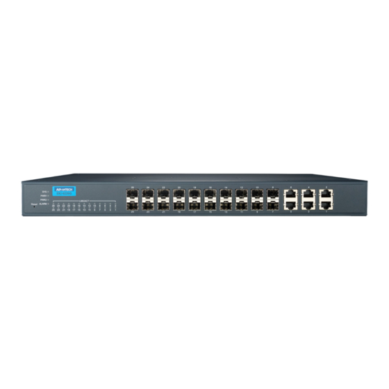
- Page 1 User Manual EKI-9226G Series 6xRJ45 + 20xSFP Port Full Gigabit L2 Managed Switch...
- Page 2 No part of this manual may be reproduced, copied, translated or transmitted in any form or by any means without the prior written permission of Advantech Co., Ltd. Information provided in this manual is intended to be accurate and reliable. How- ever, Advantech Co., Ltd.
- Page 3 Technical Support and Assistance Visit the Advantech web site at www.advantech.com/support where you can find the latest information about the product. Contact your distributor, sales representative, or Advantech's customer service center for technical support if you need additional assistance.
- Page 4 Before setting up the system, check that the items listed below are included and in good condition. If any item does not accord with the table, please contact your dealer immediately. 1 x Industrial Ethernet Switch 1 x Wall-mounting Bracket EKI-9226G Series User Manual...
- Page 5 The sound pressure level at the operator's position according to IEC 704-1:1982 is no more than 70 dB (A). DISCLAIMER: This set of instructions is given according to IEC 704-1. Advant- ech disclaims all responsibility for the accuracy of any statements contained herein. EKI-9226G Series User Manual...
- Page 6 Der arbeitsplatzbezogene Schalldruckpegel nach DIN 45 635 Teil 1000 beträgt 70dB(A) oder weiger. Haftungsausschluss: Die Bedienungsanleitungen wurden entsprechend der IEC-704-1 erstellt. Advantech lehnt jegliche Verantwortung für die Richtigkeit der in diesem Zusammenhang getätigten Aussagen ab. EKI-9226G Series User Manual...
- Page 7 Always disconnect the power from the device before servicing it. Before plugging a cable into any port, discharge the voltage stored on the cable by touching the electrical contacts to the ground surface. EKI-9226G Series User Manual...
-
Page 8: Table Of Contents
Accessing the CLI............... 25 Web Browser Configuration ..............25 3.3.1 Preparing for Web Configuration ..........25 3.3.2 System Login ................25 Chapter Managing Switch....... 26 Log In ...................... 27 Recommended Practices................ 27 4.2.1 Changing Default Password ............27 EKI-9226G Series User Manual viii... - Page 9 4.8.4 Bandwidth Guarantee ............... 100 Management ..................102 4.9.1 LLDP ..................102 4.9.2 SNMP..................105 4.9.3 Power Over Ethernet ..............108 4.9.4 TCP Modbus Settings ............... 110 4.9.5 DHCP Server ................111 4.9.6 SMTP Client................117 EKI-9226G Series User Manual...
- Page 10 4.11.5 Save Configuration ..............135 4.11.6 User Account ................135 4.11.7 N-Key..................136 4.11.8 Reset System ................136 4.11.9 Reboot Device ................136 4.12 Modbus/TCP Mapping ................137 4.12.1 Modbus/TCP Mapping Table ............ 137 Chapter Troubleshooting......154 Troubleshooting ..................155 EKI-9226G Series User Manual...
- Page 11 Serial Console Cable....................15 Figure 2.10 DB 9 Pin Position......................15 Figure 2.11 Pin Assignment......................15 Figure 2.12 Power Wiring for EKI-9226G Series ................16 Figure 2.13 Grounding Connection....................18 Figure 2.14 Terminal Receptor: Relay Contact ................18 Figure 2.15 Terminal Receptor: Power Input Contacts..............
- Page 12 QoS > General > QoS Scheduling ................93 Figure 4.93 QoS > General > CoS Mapping .................. 94 Figure 4.94 QoS > General > DSCP Mapping ................95 Figure 4.95 QoS > General > IP Precedence Mapping..............96 EKI-9226G Series User Manual...
- Page 13 Figure 4.141 Tools > Backup Manager................... 133 Figure 4.142 Tools > Upgrade Manager..................134 Figure 4.143 Tools > Dual Image ....................135 Figure 4.144 Tools > User Account ....................135 Figure 4.145 Tools > N-Key......................136 xiii EKI-9226G Series User Manual...
-
Page 14: Product Overview
Chapter Product Overview... -
Page 15: Specifications
CE FCC EN55022 Class A EN 61000-4-2 EN 61000-4-3 EN 61000-4-4 EN 61000-4-5 EN 61000-4-6 EN 61000-4-8 Shock IEC 60068-2-27 Freefall IEC 60068-2-32 Vibration IEC 60068-2-6 Power IEC 61850-3 Automation IEEE 1613 EKI-9226G Series User Manual... -
Page 16: Hardware Views
Screw terminal used to ground chassis Power block Connect cabling for power wiring. Relay Connect cabling to diagnose a power failure event. Console port Console cable port to COM port (DB9 male) on computer to RS232 managed switch (RJ45 female). EKI-9226G Series User Manual... -
Page 17: Figure 1.3 System Led Panel
Power is not being supplied to power input PWR1. ALARM Red on Defined major policies are detected. Blink red (1Hz) Defined minor policies are detected. Blink red (3Hz) Blink red (5Hz) Power off or system alarm is cleared or masked. EKI-9226G Series User Manual... -
Page 18: Dimensions
Dimensions [0.630] [0.630] 54 [2.126] 54 [2.126] 54 [2.126] 180 .15 [7.093] Ø2 10.16 [0.400] 88.92 [3.501] [1.614] 32.75 [1.289] 9.20 [0.362] Ø2 [Ø0.079] 4 [0.157] 438 [17.244] 7 [0.276] Figure 1.4 Dimensions EKI-9226G Series User Manual... -
Page 19: Switch Installation
Chapter Switch Installation... -
Page 20: Warnings
Warning! Make sure the voltage of the power source is correct before connecting the equipment to the power disconnect. Avertissement! Vérifiez que la tension de la source d'alimentation soit la correcte avant de brancher l'appareil sur le disjoncteur de l'alimentation. EKI-9226G Series User Manual... - Page 21 Avertissement! Nettoyez avec un chiffon sec. Warning! This is open type equipment and should be installed in a suitable enclo- sure. Avertissement! Cet appareil est de type ouvert. Il doit être installé dans une enceinte appropriée. EKI-9226G Series User Manual...
-
Page 22: Installation Guidelines
Connecting Hardware In this instruction, it will explain how to find a proper location for your Modbus Gate- ways, and how to connect to the network, hock up the power cable, and connect to the EKI-9226G Series. EKI-9226G Series User Manual... -
Page 23: Verifying Switch Operation
Figure 2.1 Installing the Rack Mount Brackets Align the switch with the posts on the rack cabinet. Secure the switch. SY S PW R1 EK I-9 22 6G PW R2 Res et AL AR M LN K/A Figure 2.2 Installing the Switch EKI-9226G Series User Manual... -
Page 24: Installing And Removing Sfp Modules
Figure 2.3 Removing the Dust Plug from an SFP Slot Note! Do not remove the dust plug from the SFP slot if you are not installing the transceiver at this time. The dust plug protects hardware from dust contamination. EKI-9226G Series User Manual... -
Page 25: Figure 2.4 Installing An Sfp Transceiver
Insert the fiber cable into the transceiver. The connector snaps into place and locks. Figure 2.5 Attaching a Fiber Optic Cable to a Transceiver Repeat the previous procedures to install any additional SFP transceivers in the switch. The fiber port is now setup. EKI-9226G Series User Manual... -
Page 26: Removing Sfp Modules
Hold the handle on the transceiver and pull the transceiver out of the slot. Handle Figure 2.7 Removing an SFP Transceiver Note! Replace the dust plug on the slot if you are not installing a transceiver. The dust plug protects hardware from dust contamination. EKI-9226G Series User Manual... -
Page 27: Connecting The Switch To Ethernet Ports
Pin 2 Pin 6 Pin 3 Pin 3 Pin 3 Pin 1 Pin 6 Pin 6 Pin 6 Pin 2 Figure 2.8 Ethernet Plug & Connector Pin Position Maximum cable length: 100 meters (328 ft.) for 10/100BaseT. EKI-9226G Series User Manual... -
Page 28: Connecting The Switch To Console Port
Figure 2.9 Serial Console Cable Figure 2.10 DB 9 Pin Position DB9 Connector RJ45 Connector 1 Orange/White 2 Orange 3 Green/White 4 Blue 5 Blue/White 6 Green 7 Brown/White 8 Brown RJ45 Female Male Figure 2.11 Pin Assignment EKI-9226G Series User Manual... -
Page 29: Power Supply Installation
Dual power inputs are supported and allow you to connect a backup power source. Single DC Power Redundant DC Power P2 P1 P2 P1 Chassis Chassis (pane) (pane) One DC Supply Dual DC Supplies Figure 2.12 Power Wiring for EKI-9226G Series EKI-9226G Series User Manual... -
Page 30: Considerations
Warning! If the equipment is used in a manner not specified by the manufacturer, the protection provided by the equipment may be impaired. Avertissement! Si l'appareil est utilisé d'une manière non spécifiée par le fabri- cant, la protection qu'il apporte peut se voir diminuée. EKI-9226G Series User Manual... -
Page 31: Wiring A Relay Contact
2.9.4 Wiring a Relay Contact The following section details the wiring of the relay output. The terminal block on the EKI-9226G Series is wired and then installed onto the terminal receptor located on the EKI-9226G Series. Relay Figure 2.14 Terminal Receptor: Relay Contact The terminal receptor includes a total of six pins: two for PWR1, two for PWR2 and two for a fault circuit. -
Page 32: Wiring The Power Inputs
PW2 in the same manner. Tighten the wire-clamp screws to secure the DC wires in place. Loosening Installing DC Wires Wire-clamp Screws Securing Wire- clamp Screws Figure 2.16 Installing DC Wires in a Terminal Block EKI-9226G Series User Manual... -
Page 33: Reset Button
Reset Button Reset configuration to factory default: Press and hold Reset button for 5 seconds. System reboot: Press and hold Reset button for 2 seconds. Note! Do NOT power off the Ethernet switch when loading default settings. EKI-9226G Series User Manual... -
Page 34: Configuration Utility
Chapter Configuration Utility... -
Page 35: First Time Setup
Secure Shell (SSH). An SNMP interface can be used to read/write many settings. Command Line Interface (CLI) can be used to read/write most settings. Initial setup must be done using an Ethernet connection (recommended) or the serial port. EKI-9226G Series User Manual... -
Page 36: Using The Graphical (Web) Interface
NTP Server: The IP address or domain name of an NTP (Network Time Proto- col) server from which the switch may retrieve the current time at startup. Please note that using a domain name requires that at least one domain name server be configured. EKI-9226G Series User Manual... -
Page 37: Configuring The Ethernet Ports
The general format of commands is: section parameter [value] where: – section is used to group parameters. EKI-9226G Series User Manual... -
Page 38: Accessing The Cli
In the browser’s address bar, type the switch’s default IP address (192.168.1.1). The login screen displays. Enter the user default name and password (admin / admin). Click OK on the login screen to log in. The main interface displays. EKI-9226G Series User Manual... -
Page 39: Managing Switch
Chapter Managing Switch... -
Page 40: Log In
In the User Name field, enter admin for this account. It is not necessary to change the user name, however, a change in the default settings increases the security settings. In the Password field, type in the new password. Re-type the same password in the Retype Password field. EKI-9226G Series User Manual... -
Page 41: Monitoring
Location, MAC Address, Firmware version, and more, pertaining to the system. The information is for review only. To modify the device information, see the respective item within the user interface. To access this page, click Monitoring > Device Information. Figure 4.3 Monitoring > Device Information EKI-9226G Series User Manual... -
Page 42: Logging Message
Click the drop-down menu to select a target to store the log mes- sages. Buffered: Store log messages in RAM. All log messages are cleared after system reboot. File: Store log messages in a file. EKI-9226G Series User Manual... -
Page 43: Port Monitoring
Clear Click Clear to clear the counter selections. The ensuing table for IF MIB Counters settings are informational only: ifInOctets, ifI- nUcastPkts, ifInNUcastPkts, ifInDiscards, ifOutOctets, ifOutUcastPkts, ifOutNUcast- Pkts, ifOutDiscards, ifInMulticastPkts, ifInBroadcastPkts, ifOutMulticastPkts and ifOutBroadcastPkts. EKI-9226G Series User Manual... -
Page 44: Link Aggregation
The ensuing table for Link Aggregation Group Status settings are informational only: LAG, Name, Type, Link State, Active Member and Standby Member. The ensuing table for LACP Information settings are informational only: LAG, Port, PartnerSysId, PnKey, AtKey, Sel, Mux, Receiv, PrdTx, AtState and PnState. EKI-9226G Series User Manual... -
Page 45: Lldp Statistics
Deletions, Drops and Age Outs. The ensuing table for LLDP Port Statistics settings are informational only: Port, TX Frames (Total), RX Frames (Total, Discarded and Errors), RX TLVs (Discarded and Unrecognized) and RX Ageouts (Total). EKI-9226G Series User Manual... -
Page 46: Igmp Statistics
RX, Invalid RX, Other RX, Leave RX, Report RX, General Query RX, Special Group Query RX, Special Group & Source Query RX, Leave TX, Report TX, General Query TX, Special Group Query TX and Special Group & Source Query TX. EKI-9226G Series User Manual... -
Page 47: Mld Statistics
RX, Invalid RX, Other RX, Leave RX, Report RX, General Query RX, Special Group Query RX, Special Group & Source Query RX, Leave TX, Report TX, General Query TX, Special Group Query TX and Special Group & Source Query TX. EKI-9226G Series User Manual... -
Page 48: System
Click Apply to save the values and update the screen. The ensuing table for IP Address Information settings are informational only: DHCP State, Static IP Address, Static Subnet Mask, Static Gateway, Static DNS Server 1 and Static DNS Server 2. EKI-9226G Series User Manual... -
Page 49: Ipv6 Settings
Click Apply to save the values and update the screen. The ensuing table for IPv6 Information settings are informational only: Auto Config- uration, IPv6 In Use Address, IPv6 In Use Router, IPv6 Static Address, IPv6 Static Router and DHCPv6 Client. EKI-9226G Series User Manual... -
Page 50: Dhcp Client Option 82
The ensuing table for DHCP Client Option 82 Information table settings are infor- mational only: Status, Circuit ID Format, Circuit ID String, Circuit ID Hex, Circuit ID User-Define, Remote ID Format, Remote ID String, Remote ID Hex and Remote ID User-Define. EKI-9226G Series User Manual... -
Page 51: Dhcp Auto Provision
Item Description Management VLAN Click the drop-down menu to select a defined VLAN. Apply Click Apply to save the values and update the screen. The ensuing table for Management VLAN State are informational only: Management VLAN. EKI-9226G Series User Manual... -
Page 52: System Time
Recurring From Click the drop-down menu to designate the start date and time for daylight saving time. Recurring To Click the drop-down menu to designate the end date and time for day- light saving time. EKI-9226G Series User Manual... -
Page 53: Network Port
Apply Click Apply to save the values and update the screen. The ensuing table for Network Port Information are informational only: HTTP, HTTPS, TELNET and SSH. EKI-9226G Series User Manual... -
Page 54: L2 Switching
Click Apply to save the values and update the screen. The ensuing table for Port Status settings are informational only: Port, Edit (click to enter description), Enable State, Link Status, Speed, Duplex, FlowCtrl Config and FlowCtrl Status. EKI-9226G Series User Manual... -
Page 55: Port Mirror
Enter the variable to define the TX port. Apply Click Apply to save the values and update the screen. The ensuing table for Mirror Status settings are informational only: Session ID, Des- tination Port, Ingress State, Source TX Port and Source RX Port. EKI-9226G Series User Manual... -
Page 56: Link Aggregation
Type Click the radio button to specify the type mode: Static or LACP. Ports Click the drop-down menu to select designated ports: FE1-8 or GE1-2. Apply Click Apply to save the values and update the screen. EKI-9226G Series User Manual... -
Page 57: Figure 4.21 L2 Switching > Link Aggregation > Lag Port Settings
Figure 4.22 L2 Switching > Link Aggregation > LACP Priority Settings The following table describes the items in the previous figure. Item Description System Priority Enter the value (1-65535) to designate the LACP system priority. Apply Click Apply to save the values and update the screen. EKI-9226G Series User Manual... -
Page 58: Figure 4.23 L2 Switching > Link Aggregation > Lacp Port Settings
Passive: Enables LACP only when an LACP device is detected (default state). Apply Click Apply to save the values and update the screen. The ensuing table for LACP Port Information settings are informational only: Port Name, Priority, Timeout and Mode. EKI-9226G Series User Manual... -
Page 59: Q Vlan
Enter the prefix to be used by the VLAN list entry in the previous field. Prefix Apply Click Apply to save the values and update the screen. The ensuing table for VLAN Table settings are informational only: VLAN ID, VLAN Name, VLAN Type and Edit (click to enter VLAN name). EKI-9226G Series User Manual... -
Page 60: Figure 4.25 L2 Switching > 802.1Q Vlan > Pvid Settings
The default is Disabled. Apply Click Apply to save the values and update the screen. The ensuing table for Port VLAN Status settings are informational only: Port, Inter- face VLAN Mode, PVID, Accept Frame Type and Ingress Filtering. EKI-9226G Series User Manual... -
Page 61: Figure 4.26 L2 Switching > 802.1Q Vlan > Port To Vlan
Trunk: Port hybrid model. Tunnel: Port hybrid model. Membership Displays the assigned membership status of the port entry, options include: Forbidden, Excluded Tagged or Untagged. Apply Click Apply to save the values and update the screen. EKI-9226G Series User Manual... -
Page 62: Q-In-Q
Enter the outer VLAN handled by the switch giving the attached type machine a single-tagged 802.1Q VLAN frame. Apply Click Apply to save the values and update the screen. The ensuing table for QinQ Global Information settings are informational only: Outer VLAN Ethertype. EKI-9226G Series User Manual... -
Page 63: Figure 4.28 L2 Switching > Q-In-Q > Port Settings
NNI: Selects a network-to-network interface which specifies communication between two specified networks. Click Apply to save the values and update the screen. Apply The ensuing table for QinQ Port Information settings are informational only: Port, Outer PVID and Outer Mode. EKI-9226G Series User Manual... -
Page 64: Garp
12000. An instance of this timer exists for each GARP participant for each port. Apply Click Apply to save the values and update the screen. The ensuing table for GARP Information settings are informational only: Join Time, Leave Time and Leave All Time. EKI-9226G Series User Manual... -
Page 65: Figure 4.30 L2 Switching > Garp > Gvrp Settings
Click Apply to save the values and update the screen. The ensuing table for GMRP Information settings are informational only: GMRP. The ensuing table for Multicast Groups settings are informational only: VLAN ID, MAC Address, Type and Member Ports. EKI-9226G Series User Manual... -
Page 66: 802.3Az Eee
The following table describes the items in the previous figure. Item Description Unknown Multicast Select the configuration protocol: Drop, Flood, or Router Port, to apply Action for any unknown multicast event. Apply Click Apply to save the values and update the screen. EKI-9226G Series User Manual... -
Page 67: Figure 4.34 L2 Switching > Multicast > Igmp Snooping > Igmp Settings
No., VLAN ID, IGMP Snooping Operation State, Router Ports Auto Learn, Query Robustness, Query Interval (sec.), Query Max Response Interval (sec.), Last Mem- ber Query count, Last Member Query Interval (sec), Immediate Leave and Edit (click to modify the settings). EKI-9226G Series User Manual... -
Page 68: Figure 4.35 L2 Switching > Multicast > Igmp Snooping > Igmp Querier
Enter the port numbers to associate with the static group. Click Add to add an IGMP group. The ensuing table for IGMP Static Groups Status settings are informational only: VLAN ID, Group IP Address, Member Ports and Modify. EKI-9226G Series User Manual... -
Page 69: Figure 4.37 L2 Switching > Multicast > Mld Snooping > Mld Settings
No., VLAN ID, MLD Snooping Operation State, Router Ports Auto Learn, Query Robustness, Query Interval (sec.), Query Max Response Interval (sec.), Last Mem- ber Query count, Last Member Query Interval (sec), Immediate Leave and Edit (click to modify the settings). EKI-9226G Series User Manual... -
Page 70: Figure 4.38 L2 Switching > Multicast > Mld Snooping > Mld Querier
Enter the ports designated with the static group. Click Add to add a MLD static group. The ensuing table for MLD Static Groups Status settings are informational only: VLAN ID, Group IP Address, Member Ports and Modify. EKI-9226G Series User Manual... -
Page 71: Jumbo Frame
Enter the variable in bytes (1518 to 9216) to define the jumbo frame (Bytes) size. Apply Click Apply to save the values and update the screen. The ensuing table for Jumbo Frame Config settings are informational only: Jumbo Frame (Bytes). EKI-9226G Series User Manual... -
Page 72: Spanning Tree
MSTP-Operation: 802.1s operation. Apply Click Apply to save the values and update the screen. The ensuing table for STP Information settings are informational only: STP, BPDU Forward, BPDU Guard, PathCost Method and Force Version. EKI-9226G Series User Manual... -
Page 73: Figure 4.42 L2 Switching > Spanning Tree > Stp Port Settings
BPDU formats. Apply Click Apply to save the values and update the screen. The ensuing table for STP Port Status settings are informational only: Port, Admin Enable, Path Cost, Edge Port and P2P MAC. EKI-9226G Series User Manual... -
Page 74: Figure 4.43 L2 Switching > Spanning Tree > Stp Bridge Settings
Forward Delay, Max Age, Tx Hold Count and Hello Time. The ensuing table for STP Bridge Status settings are informational only: Bridge Identifier, Designated Root Bridge, Root Path Cost, Designated Bridge, Root Port and Last Topology Change. EKI-9226G Series User Manual... -
Page 75: Figure 4.44 L2 Switching > Spanning Tree > Stp Port Advanced Settings
Enter the identifier for the Revision Configuration, range: 0 to 65535 (default: 0). Click Apply to save the values and update the screen. Apply The ensuing table for MST Configuration Identification Information settings are informational only: Configuration Name and Revision Level. EKI-9226G Series User Manual... -
Page 76: Figure 4.46 L2 Switching > Spanning Tree > Mst Instance Id Settings
Click the drop-down menu set the bridge priority in the specified MST instance Apply Click Apply to save the values and update the screen. The ensuing table for MST Instance Priority Information settings are informational only: MSTI ID, Priority and Action. EKI-9226G Series User Manual... -
Page 77: X-Ring Elite
Item Description State Select Enabled or Disabled to setup the X-Ring Elite mode. Apply Click Apply to save the values and update the screen. The ensuing table for Information settings are informational only: X-Ring Elite State. EKI-9226G Series User Manual... -
Page 78: X-Ring Pro
Item Description State Select Enabled or Disabled to setup the X-Ring Pro mode. Click Apply to save the values and update the screen. Apply The ensuing table for Information settings are informational only: X-Ring Pro State. EKI-9226G Series User Manual... -
Page 79: Figure 4.51 L2 Switching > X-Ring Pro > X-Ring Pro Groups > X-Ring Pro Groups Settings
Figure 4.53 L2 Switching > X-Ring Pro > X-Ring Pro Groups > Couple Setting The following table describes the items in the previous figure. Item Description Couple Ring ID Enter a number to specifies a ranging from 1 to 255 to identify a given X-Ring group. EKI-9226G Series User Manual... -
Page 80: Figure 4.54 L2 Switching > X-Ring Pro > X-Ring Pro Groups > Pair Settings
Click Add to save the values and update the screen. The ensuing table for Information settings are informational only: Ring ID, Mode, Role, Operation State, Port 1, Forwarding State, Port 2, Forwarding State and Delete (click to delete the desired Ring ID). EKI-9226G Series User Manual... -
Page 81: Loopback Detection
Enter the variable in seconds (60 to 1000000) to define the delay before recovery. Apply Click Apply to save the values and update the screen. The ensuing table for Loopback Detection Global Information settings are infor- mational only: State, Interval and Recover Time. EKI-9226G Series User Manual... -
Page 82: Erps
The following table describes the items in the previous figure. Item Description State Click Enabled or Disabled to enable ERPS settings. Apply Click Apply to save the values and update the screen. The ensuing table for Information settings are informational only: ERPS State. EKI-9226G Series User Manual... -
Page 83: Figure 4.59 L2 Switching > Erps > Erps Groups
The ensuing table for Information settings are informational only: ERP Instance, Ring ID, Role, State, East Link, West Link, MEL, R-APS Channel VLAN, Traffic Chan- nel Instance, Type, WTR Timer, Guard Timer, Hold-off Timer and Delete (Click Delete to delete the desired Ring ID). EKI-9226G Series User Manual... -
Page 84: Mac Address Table
Enter the variable (10 to 630) to define the time required for aging. Apply Click Apply to save the values and update the screen. The ensuing table for Dynamic Address Status settings are informational only: Aging time. EKI-9226G Series User Manual... -
Page 85: Dynamic Forwarding Table
Click Clear to clear the MAC Address Information table. Clear The ensuing table for MAC Address Information settings are informational only: MAC Address, VLAN, Type, Port and Add to Static MAC (click to add the MAC address to static MAC address list). EKI-9226G Series User Manual... -
Page 86: Security
Included: include preamble & IFG (20 bytes) when count ingress storm control rate. Apply Click Apply to save the values and update the screen. The ensuing table for Storm Control Global Information settings are informational only: Unit and Preamble & IFG. EKI-9226G Series User Manual... -
Page 87: Figure 4.64 Security > Storm Control > Port Settings
Click Apply to save the values and update the screen. Apply The ensuing table for Storm Control Port Information settings are informational only: Port, Port State, Broadcast (Kbps), Unknown Multicast (Kbps), Unknown Uni- cast (Kbps) and Action. EKI-9226G Series User Manual... -
Page 88: Port Security
Select Unprotected or Protected to define the port type. Apply Click Apply to save the values and update the screen. The ensuing table for Protected Ports Status settings are informational only: Pro- tected Ports and Unprotected Ports. EKI-9226G Series User Manual... -
Page 89: Dos Prevention
The following table describes the items in the previous figure. Item Description DMAC = SMAC Click Enabled or Disabled to define DMAC-SMAC for the DoS Global settings. Click Enabled or Disabled to define LAND for the DoS Global set- LAND tings. EKI-9226G Series User Manual... - Page 90 Fragment Size, ICMP Fragment Packets, IPv4 Ping Max Packet Size, IPv6 Ping Max Packet Size, Smurf Attack, TCP Min Header Length, TCP Syn (SPORT < 1024), Null Scan Attack, X-Mas Scan Attack, TCP SYN-FIN Attack, TCP SYN-RST Attack and TCP Fragment (Offset = 1). EKI-9226G Series User Manual...
-
Page 91: Applications
Click Apply to save the values and update the screen. Disconnect Click Disconnect to disable the current Telnet service. The ensuing table for Telnet Information settings are informational only: Telnet Ser- vice and Current Telnet Sessions Count. EKI-9226G Series User Manual... -
Page 92: Figure 4.70 Security > Applications > Ssh
Enter the variable in minutes (0 to 86400) to define the timeout period for the HTTP session. Apply Click Apply to save the values and update the screen. The ensuing table for HTTP Information settings are informational only: HTTP Ser- vice and Session Timeout. EKI-9226G Series User Manual... -
Page 93: Figure 4.72 Security > Applications > Https
Enter the variable in minutes (0 to 86400) to define the timeout period for the HTTP session. Click Apply to save the values and update the screen. Apply The ensuing table for HTTPS Information settings are informational only: HTTPS Service and Session Timeout. EKI-9226G Series User Manual... -
Page 94: Figure 4.73 Security > 802.1X > 802.1X Global Settings
Apply Click Apply to save the values and update the screen. The ensuing table for 802.1x Information settings are informational only: 802.1x State, Server IP, Server Port, Accounting Port, Security Key and Reauth Period. EKI-9226G Series User Manual... -
Page 95: Ip Security
Click Enabled or Disabled to define the global setting for the IP secu- rity function. Apply Click Apply to save the values and update the screen. The ensuing table for IP Security Status settings are informational only: IP Security. EKI-9226G Series User Manual... -
Page 96: Security Login
The following table describes the items in the previous figure. Item Description State Click Enabled or Disabled to set up security login global setting sta- tus. Apply Click Apply to save the values and update the screen. EKI-9226G Series User Manual... -
Page 97: Figure 4.78 Security > Security Login > Global Settings > Radius Settings
Click Apply to save the values and update the screen. The ensuing table for Global Information settings are informational only: State, RADIUS Server IP, RADIUS Server Port, RADIUS Security Key, TACACS Server IP, TACACS Server Port and TACACS Security Key. EKI-9226G Series User Manual... -
Page 98: Figure 4.80 Security > Security Login > Access Control Settings > Security Login Type Settings
Click Enabled or Disabled to set up SSH. Apply Click Apply to save the values and update the screen. The ensuing table for Access Control Information settings are informational only: Login Type, HTTP, TELNET and SSH. EKI-9226G Series User Manual... -
Page 99: Access Control List
Click the drop down menu to select the queue. The function is only available when Action is Assign Queue. Status Click the drop down menu to select the MAC ACL status. Options include: Active or Inactive. Click Add to add a MAC ACL entry. EKI-9226G Series User Manual... -
Page 100: Figure 4.83 Security > Access Control List > Ip Acl > Entry Settings
Enter a value to specify the L4 source port. Portlist Select the port to configure for the IP ACL function. Action Click the drop down menu to select the IP ACL action. Options include: Permit, Drop or Assign Queue. EKI-9226G Series User Manual... -
Page 101: Ip Source Guard
The following table describes the items in the previous figure. Item Description Source MAC Enter the MAC address to set source MAC address. Address Source IP Address Enter the IP address to set source IP address. EKI-9226G Series User Manual... -
Page 102: Dhcp Snooping
Description DHCP Snooping Port Select the port to configure for the DHCP Snooping port. Select Enabled Click Enabled or Disabled to enable DHCP Snooping port. Apply Click Apply to save the values and update the screen. EKI-9226G Series User Manual... -
Page 103: Arp Spoofing
Address Source IP Address Enter the IP address to set source IP address. Click Add to add an ARP spoofing. The ensuing table for Entry Information settings are informational only: Source MAC, Source IP and Modify. EKI-9226G Series User Manual... -
Page 104: Qos
Description Select Disabled or Basic to setup the QoS function. QoS Mode Click Apply to save the values and update the screen. Apply The ensuing table for QoS Global Information settings are informational only: QoS Mode. EKI-9226G Series User Manual... -
Page 105: Figure 4.91 Qos > General > Qos Settings
QoS function. Click Apply to save the values and update the screen. Apply The ensuing table for QoS Status settings are informational only: Port, CoS value, Remark CoS, Remark DSCP and Remark IP Precedence. EKI-9226G Series User Manual... -
Page 106: Figure 4.92 Qos > General > Qos Scheduling
% of WRR Bandwidth Displays the allotted bandwidth for the queue entry in percentage val- ues. Apply Click Apply to save the values and update the screen. The ensuing table for Queue Information settings are informational only: Strict Prior- ity Queue Number. EKI-9226G Series User Manual... -
Page 107: Figure 4.93 Qos > General > Cos Mapping
Click Apply to save the values and update the screen. The ensuing table for CoS Mapping Information settings are informational only: CoS and Mapping to Queue. The ensuing table for Queue Mapping Information settings are informational only: Queue and Mapping to CoS. EKI-9226G Series User Manual... -
Page 108: Figure 4.94 Qos > General > Dscp Mapping
Click Apply to save the values and update the screen. The ensuing table for DSCP Mapping Information settings are informational only: DSCP and Mapping to Queue. The ensuing table for Queue Mapping Information settings are informational only: Queue and Mapping to DSCP. EKI-9226G Series User Manual... -
Page 109: Figure 4.95 Qos > General > Ip Precedence Mapping
The ensuing table for IP Precedence Mapping Information settings are informa- tional only: IP Precedence and Mapping to Queue. The ensuing table for Queue Mapping Information settings are informational only: Queue and Mapping to IP Precedence. EKI-9226G Series User Manual... -
Page 110: Qos Basic Mode
Select Enabled or Disabled to set the port’s trust state status. Apply Click Apply to save the values and update the screen. The ensuing table for QoS Port Status settings are informational only: Port and Trust State. EKI-9226G Series User Manual... -
Page 111: Rate Limit
To access this page, click QoS > Rate Limit > Egress Bandwidth Control. Figure 4.99 QoS > Rate Limit > Egress Bandwidth Control The following table describes the items in the previous figure. Item Description Port Enter the port number to set the Egress Bandwidth Control. EKI-9226G Series User Manual... -
Page 112: Figure 4.100 Qos > Rate Limit > Egress Queue
Enter the value in Kbps (16 to 1000000) to set the CIR rate for the Egress queue. Apply Click Apply to save the values and update the screen. The ensuing table for FE1 Egress Per Queue Status settings are informational only: Queue Id and Egress Rate Limit (Kbps). EKI-9226G Series User Manual... -
Page 113: Bandwidth Guarantee
Click the check box to enable the force mode. Apply Click Apply to save the values and update the screen. The ensuing table for Ingress Bandwidth Control Status settings are informational only: Status, Guarantee Bandwidth, Guarantee Type, UDP Source Port and Force Mode. EKI-9226G Series User Manual... -
Page 114: Figure 4.102 Qos > Bandwidth Guarantee > Utilzation
Figure 4.102 QoS > Bandwidth Guarantee > Utilzation The following table describes the items in the previous figure. Item Description Refresh period Click the drop-down menu to select refresh time. Apply Click Apply to save the values and update the screen. EKI-9226G Series User Manual... -
Page 115: Management
Click Apply to save the values and update the screen. The ensuing table for LLDP Global Config settings are informational only: LLDP Enabled, LLDP PDU Disable Action, Transmission Interval, Holdtime Multiplier, Reinitialization Delay and Transmit Delay. EKI-9226G Series User Manual... -
Page 116: Figure 4.104 Management > Lldp > Lldp Port Settings > Lldp Port Configuration
System Capability: To include system capability TLV in LLDP frames. 802.3 MAC-PHY: 802.3 Link Aggregation: 802.3 Maximum Frame Size: Management Address: 802.1 PVID: Click Apply to save the values and update the screen. Apply EKI-9226G Series User Manual... -
Page 117: Figure 4.106 Management > Lldp > Lldp Port Settings > Vlan Name Tlv Vlan Selection
Figure 4.107 Management > LLDP > LLDP Remote Device Info The following table describes the items in the previous figure. Item Description Detail Click to display the device details. Delete Click to delete the selected devices. Refresh Click to refresh the remote device information list. EKI-9226G Series User Manual... -
Page 118: Snmp
To access this page, click Management > SNMP > SNMP Community. Figure 4.109 Management > SNMP > SNMP Community The following table describes the items in the previous figure. Item Description Community Name Enter a community name (up to 20 characters). EKI-9226G Series User Manual... -
Page 119: Figure 4.110 Management > Snmp > Snmpv3 Engineid
Enter a user name (up to 32 characters) to create an SNMP profile. Access Right Click read-only or read-write to define the access right for the profile. Encrypted Click the option to set the encrypted option for the user setting. EKI-9226G Series User Manual... -
Page 120: Figure 4.112 Management > Snmp > Snmp Trap
Click Add to save the values and update the screen. The ensuing table for Trap Host Status settings are informational only: No., IP Address, Community Name, Version and Delete (click to delete the desired IP address). EKI-9226G Series User Manual... -
Page 121: Power Over Ethernet
Apply Click Apply to save the values and update the screen. The ensuing table for PoE System Information settings are informational only: Firm- ware Version, Maximum Power Available, Actual Power Consumption and Overload Disconnect Type. EKI-9226G Series User Manual... -
Page 122: Figure 4.114 Management > Power Over Ethernet > Poe Port Settings
PoE Port Status To access this page, click Management > Power Over Ethernet > PoE Port Status. The ensuing table for PoE Port Status settings are informational only: Port, Current (mA), Voltage (V), Power (W) and Temp. (°C). EKI-9226G Series User Manual... -
Page 123: Tcp Modbus Settings
Enter the value (1 to 86400) to define the timeout period between transport time. Apply Click Apply to save the values and update the screen. The ensuing table for TCP Modbus Status settings are informational only: TCP Mod- bus status and TCP Modbus time out. EKI-9226G Series User Manual... -
Page 124: Dhcp Server
Click Restart to have the switch perform a system restart function. In the event that the IP settings are changed, the DHCP server must be restarted for the IP settings to take effect. The ensuing table for Status Information settings are informational only: DHCP Server Service. EKI-9226G Series User Manual... -
Page 125: Figure 4.117 Management > Dhcp Server > Global Settings
Click Apply to save the values and update the screen. The ensuing table for Global Information settings are informational only: Lease Time, Low IP Address, High IP Address, Subnet Mask, Gateway, DNS and Clear (click to clear IP pool). EKI-9226G Series User Manual... -
Page 126: Figure 4.118 Management > Dhcp Server > Port Settings
Click Apply to save the values and update the screen. The ensuing table for Port Information settings are informational only: Port, Low IP Address, High IP Address, Subnet Mask, Gateway, DNS, Edit (click to modify the settings) and Clear (click to clear the settings). EKI-9226G Series User Manual... -
Page 127: Figure 4.119 Management > Dhcp Server > Vlan Settings
The ensuing table for Entry Information settings are informational only: Entry ID, VLAN ID, Low IP Address, High IP Address, Subnet Mask, Gateway, DNS, Edit (click to modify the settings) and Clear (click to clear the settings). EKI-9226G Series User Manual... -
Page 128: Figure 4.120 Management > Dhcp Server > Option 82 Settings
Entry ID, Circuit ID Format, Circuit ID Con- tent, Remote ID Format, Remote ID Content, Low IP Address, High IP Address, Sub- net Mask, Gateway, DNS, Edit (click to modify the settings) and Clear (click to clear the settings). EKI-9226G Series User Manual... -
Page 129: Figure 4.121 Management > Dhcp Server > Client Mac Settings
4.9.5.7 Lease Entry To access this page, click Management > DHCP Server > Lease Entry. The ensuing table for Lease entry Table settings are informational only: IP Address, Client Mac, Start Time, End Time and Type. EKI-9226G Series User Manual... -
Page 130: Smtp Client
Server Port Enter the port number to designate the port associated with the server IP address. Sender Mail Enter the email address of the sender client. Apply Click Apply to save the values and update the screen. EKI-9226G Series User Manual... -
Page 131: Figure 4.124 Management > Smtp Client > Profile Settings > Profile Target Mail Settings
The following table describes the items in the previous figure. Item Description Title Assign the title of the email. The maximum length is 20 characters (alphanumeric, symbols (. (dot), _ (underline), - (dash line) and space). EKI-9226G Series User Manual... -
Page 132: Rmon
Click Apply to save the values and update the screen. Apply The ensuing table for Statistics Information settings are informational only: Index, Port, Drop Events, Octets, Packets, Broadcast, Multicast, Owner and Delete (click to delete the desired index). EKI-9226G Series User Manual... -
Page 133: Figure 4.127 Management > Rmon > Rmon History
Enter the name of the owner of the RMON history group. Apply Click Apply to save the values and update the screen. The ensuing table for History Information settings are informational only: Index, Port, Buckets Requested, Interval, Owner and Delete (click to delete the desired index). EKI-9226G Series User Manual... -
Page 134: Figure 4.128 Management > Rmon > Rmon Alarm
Click Apply to save the values and update the screen. The ensuing table for Alarm Information settings are informational only: Index, Interval, Variable, Sample Type, Rising Threshold, Falling Threshold, Rising Event Index, Falling Event Index, Owner and Delete (click to delete the desired index). EKI-9226G Series User Manual... -
Page 135: Figure 4.129 Management > Rmon > Rmon Event
Enter the name of the owner of the RMON event. Apply Click Apply to save the values and update the screen. The ensuing table for Event Information settings are informational only: Index, Description, Type, Community, Owner and Delete (click to delete the desired index). EKI-9226G Series User Manual... -
Page 136: Ntp Server
The ensuing table for NTP Server Status settings are informational only: INTP Server Status, Manual Time, Server AddressInformation Value, Server 1, Server 2, Server 3, Server 4, Server 5, Server 6, Server 7, Server 8, Server 9 and Server 10. EKI-9226G Series User Manual... -
Page 137: Diagnostics
Click Copper Test to display the test result for the selected port. The ensuing table for Test Result settings are informational only: Port, Channel A, Cable Length A, Channel B, Cable Length B, Channel C, Cable Length C, Channel D and Cable Length D. EKI-9226G Series User Manual... -
Page 138: Ping Test
1. The value ranges from 1 to 5. The interval entered is not retained across a power cycle. Size (in bytes) Enter the size of ping packet. The default value is 56. The value ranges from 8 to 5120. The size entered is not retained across a power cycle. EKI-9226G Series User Manual... -
Page 139: Ipv6 Ping Test
Click Apply to display ping result for the IP address. 4.10.3 IPv6 Ping Test The IPv6 Ping Test page allows you to configure the Ping Test for IPv6. To access this page, click Diagnostics > IPv6 Ping Test. Figure 4.133 Diagnostics > IPv6 Ping Test EKI-9226G Series User Manual... - Page 140 64 bytes from 2222::717: icmp6_seq=3 ttl=128 time=0.0 ms --- 2222::717 ping statistics --- 4 packets transmitted, 4 packets received, 0% packet loss round-trip min/avg/max = 0.0/2.5/10.0 ms Click Apply to display ping result for the IP address. Apply EKI-9226G Series User Manual...
-
Page 141: System Log
To access this page, click Diagnostics > System Log > Local Logging. Figure 4.135 Diagnostics > System Log > Local Logging The following table describes the items in the previous figure. Item Description Target Enter the local logging target. EKI-9226G Series User Manual... -
Page 142: Figure 4.136 Diagnostics > System Log > System Log Server
Indicates action must be taken immediately crit: Indicates critical conditions error: Indicates error conditions warning: Indicates warning conditions notice: Indicates normal but significant conditions info: Indicates informational messages debug: Indicates debug-level messages EKI-9226G Series User Manual... -
Page 143: Ddm
Click Enabled or Disabled to set the alarm state. Low Alarm Click Enabled or Disabled to set the alarm state. Low Warning Click Enabled or Disabled to set the alarm state. Apply Click Apply to save the values and update the screen. EKI-9226G Series User Manual... -
Page 144: Led Indication
The ensuing table for LED Information settings are informational only: Alarm. The ensuing table for Event Information settings are informational only: LED (click the drop down menu to select LED), Event, State, and Delete (click to delete the desired event). EKI-9226G Series User Manual... -
Page 145: Tools
Displays the device’s IP MAC address. Firmware Version Displays the device’s firmware version. System Indicator Displays the device’s system indicator. Previous Click Previous to back to previous page. Next Click Next to go to next page. EKI-9226G Series User Manual... -
Page 146: Backup Manager
Click a type to define the backup method: image: running configura- tion, startup configuration, custom configuration, flash log, or buffered log. Image Click the format for the image type: Active or Backup. Click Backup to backup the settings. Backup EKI-9226G Series User Manual... -
Page 147: Upgrade Manager
Click a type to define the upgrade method: image, startup configura- tion, running configuration, or custom configuration. Image Click the format for the image type: Active, Backup, or auto. Upgrade Click Upgrade to upgrade to the current version. EKI-9226G Series User Manual... -
Page 148: Dual Image
To access this page, click Tools > User Account. Figure 4.144 Tools > User Account The following table describes the items in the previous figure. Item Description User Name Enter the name of the new user entry. EKI-9226G Series User Manual... -
Page 149: N-Key
Reset settings take effect after a system reboot. 4.11.9 Reboot Device To access this page, click Tools > Reboot Device. Click Reboot to reboot the switch. Any configuration changes you have made since the last time you issued a save will be lost. EKI-9226G Series User Manual... -
Page 150: Modbus/Tcp Mapping
4.12 Modbus/TCP Mapping The data map addresses of Advantech switches shown in the following table start from Modbus address 30001 for function code 4. In the given example, the address offset 0x1000 (hex) equals Modbus address 34097, while the address offset 0x1100 (hex) equals Modbus address 34353. - Page 151 Port 11 Status 1 word 16 bits HEX 0x100A 34107 Port 12 Status 1 word 16 bits HEX 0x100B 34108 Port 13 Status 1 word 16 bits HEX 0x100C 34109 Port 14 Status 1 word 16 bits HEX 0x100D 34110 EKI-9226G Series User Manual...
- Page 152 Port 24 Speed 1 word 16 bits HEX 0x1117 34376 Port 25 Speed 1 word 16 bits HEX 0x1118 34377 Port 26 Speed 1 word 16 bits HEX 0x1119 34378 Port 27 Speed 1 word 16 bits HEX 0x111A 34379 EKI-9226G Series User Manual...
- Page 153 0x1215 34630 Control Port 23 Flow 1 word 16 bits HEX 0x1216 34631 Control Port 24 Flow 1 word 16 bits HEX 0x1217 34632 Control Port 25 Flow 1 word 16 bits HEX 0x1218 34633 Control EKI-9226G Series User Manual...
- Page 154 35321 Description words chars Port 12 ASCII 0x14DC 35341 Description words chars Port 13 ASCII 0x14F0 35361 Description words chars Port 14 ASCII 0x1504 35381 Description words chars Port 15 ASCII 0x1518 35401 Description words chars EKI-9226G Series User Manual...
- Page 155 Port 8 Link Up 1 word 16 bits HEX 0x1707 35896 Counter Port 9 Link Up 1 word 16 bits HEX 0x1708 35897 Counter Port 10 Link 1 word 16 bits HEX 0x1709 35898 Up Counter EKI-9226G Series User Manual...
- Page 156 0x1802 36147 Voltage Port 4 PoE 1 word 16 bits HEX 0x1803 36148 Voltage Port 5 PoE 1 word 16 bits HEX 0x1804 36149 Voltage Port 6 PoE 1 word 16 bits HEX 0x1805 36150 Voltage EKI-9226G Series User Manual...
- Page 157 PoE Current (mA) 0x183F 36208 Ex: poe current = 13 Received MODBUS response: 0x000D Port 1 PoE 1 word 16 bits HEX 0x1820 36177 Current Port 2 PoE 1 word 16 bits HEX 0x1821 36178 Current EKI-9226G Series User Manual...
- Page 158 0x183C 36205 Current Port 30 PoE 1 word 16 bits HEX 0x183D 36206 Current Port 31 PoE 1 word 16 bits HEX 0x183E 36207 Current Port 32 PoE 1 word 16 bits HEX 0x183F 36208 Current EKI-9226G Series User Manual...
- Page 159 0x1858 36233 Power Port 26 PoE 1 word 16 bits HEX 0x1859 36234 Power Port 27 PoE 1 word 16 bits HEX 0x185A 36235 Power Port 28 PoE 1 word 16 bits HEX 0x185B 36236 Power EKI-9226G Series User Manual...
- Page 160 0x1873 36260 Temperature Port 21 PoE 1 word 16 bits HEX 0x1874 36261 Temperature Port 22 PoE 1 word 16 bits HEX 0x1875 36262 Temperature Port 23 PoE 1 word 16 bits HEX 0x1876 36263 Temperature EKI-9226G Series User Manual...
- Page 161 64 bits HEX 0x2030 38241 Packets words Port 14 Tx 64 bits HEX 0x2034 38245 Packets words Port 15 Tx 64 bits HEX 0x2038 38249 Packets words Port 16 Tx 64 bits HEX 0x203C 38253 Packets words EKI-9226G Series User Manual...
- Page 162 64 bits HEX 0x2114 38469 Packets words Port 7 Rx 64 bits HEX 0x2118 38473 Packets words Port 8 Rx 64 bits HEX 0x211C 38477 Packets words Port 9 Rx 64 bits HEX 0x2120 38481 Packets words EKI-9226G Series User Manual...
- Page 163 Word 1 = 0x4130 Port 1 Tx Error 32 bits HEX 0x2200 38705 Packets words Port 2 Tx Error 32 bits HEX 0x2202 38707 Packets words Port 3 Tx Error 32 bits HEX 0x2204 38709 Packets words EKI-9226G Series User Manual...
- Page 164 Error Packets words Port 30 Tx 32 bits HEX 0x223A 38763 Error Packets words Port 31 Tx 32 bits HEX 0x223C 38765 Error Packets words Port 32 Tx 32 bits HEX 0x223E 38767 Error Packets words EKI-9226G Series User Manual...
- Page 165 Error Packets words Port 24 Rx 32 bits HEX 0x232E 39007 Error Packets words Port 25 Rx 32 bits HEX 0x2330 39009 Error Packets words Port 26 Rx 32 bits HEX 0x2332 39011 Error Packets words EKI-9226G Series User Manual...
- Page 166 Error Packets words Port 30 Rx 32 bits HEX 0x233A 39019 Error Packets words Port 31 Rx 32 bits HEX 0x233C 39021 Error Packets words Port 32 Rx 32 bits HEX 0x233E 39023 Error Packets words EKI-9226G Series User Manual...
- Page 167 Chapter Troubleshooting...
-
Page 168: Chapter 5 Troubleshooting
If the LED indicators are normal and the connected cables are correct but pack- ets still cannot be transmitted, please check the user system's Ethernet device configuration or status. EKI-9226G Series User Manual... - Page 169 No part of this publication may be reproduced in any form or by any means, electronic, photocopying, recording or otherwise, without prior written permis- sion of the publisher. All brand and product names are trademarks or registered trademarks of their respective companies. © Advantech Co., Ltd. 2019...
Need help?
Do you have a question about the EKI-9226G Series and is the answer not in the manual?
Questions and answers