
Subscribe to Our Youtube Channel
Related Manuals for Advantech EKI-7708 Series


Summary of Contents for Advantech EKI-7708 Series
- Page 1 User Manual EKI-7708 Series 4FE/4GE + 4G SFP Port Gigabit Managed Redundant Industrial Switch 4FE/4GE PoE + 4G SFP Port Gigabit Managed Redundant Industrial PoE Switch...
- Page 2 No part of this manual may be reproduced, copied, translated or transmitted in any form or by any means without the prior written permission of Advantech Co., Ltd. Information provided in this manual is intended to be accurate and reliable.
- Page 3 Technical Support and Assistance Visit the Advantech web site at www.advantech.com/support where you can find the latest information about the product. Contact your distributor, sales representative, or Advantech's customer service center for technical support if you need additional assistance.
- Page 4 Before setting up the system, check that the items listed below are included and in good condition. If any item does not accord with the table, please contact your dealer immediately. 1 x Industrial Ethernet Switch 2 x Wall-mounting Bracket 1 x DIN-Rail mounting Bracket and Screws EKI-7708 Series User Manual...
- Page 5 The sound pressure level at the operator's position according to IEC 704-1:1982 is no more than 70 dB (A). DISCLAIMER: This set of instructions is given according to IEC 704-1. Advantech disclaims all responsibility for the accuracy of any statements contained herein.
- Page 6 Der arbeitsplatzbezogene Schalldruckpegel nach DIN 45 635 Teil 1000 beträgt 70dB(A) oder weiger. Haftungsausschluss: Die Bedienungsanleitungen wurden entsprechend der IEC- 704-1 erstellt. Advantech lehnt jegliche Verantwortung für die Richtigkeit der in die- sem Zusammenhang getätigten Aussagen ab. EKI-7708 Series User Manual...
- Page 7 Always disconnect the power from the device before servicing it. Before plugging a cable into any port, discharge the voltage stored on the cable by touching the electrical contacts to the ground surface. EKI-7708 Series User Manual...
-
Page 8: Table Of Contents
Accessing the CLI............... 30 Web Browser Configuration ..............31 3.3.1 Preparing for Web Configuration ..........31 3.3.2 System Login ................31 Chapter Managing Switch....... 32 Log In ...................... 33 Recommended Practices................ 33 4.2.1 Changing Default Password ............33 EKI-7708 Series User Manual viii... - Page 9 Bandwidth Guarantee ............... 101 Management ..................102 4.9.1 LLDP ..................102 4.9.2 SNMP..................106 4.9.3 Power Over Ethernet ..............108 4.9.4 TCP Modbus Settings ............... 110 4.9.5 DHCP Server ................111 4.9.6 SMTP Client................115 4.9.7 RMON ..................117 EKI-7708 Series User Manual...
- Page 10 4.11.5 Save Configuration ..............130 4.11.6 User Account ................130 4.11.7 N-Key..................131 4.11.8 Reset System ................131 4.11.9 Reboot Device ................131 4.12 Modbus/TCP Mapping ................132 4.12.1 Modbus/TCP Mapping Table ............ 132 Chapter Troubleshooting......148 Troubleshooting ..................149 EKI-7708 Series User Manual...
- Page 11 Serial Console Cable....................20 Figure 2.14 DB 9 Pin Position......................20 Figure 2.15 Pin Assignment......................20 Figure 2.16 Power Wiring for EKI-7708 Series................21 Figure 2.17 Grounding Connection....................23 Figure 2.18 Terminal Receptor: Relay Contact ................23 Figure 2.19 Terminal Receptor: Relay Contact (PoE model) ............23 Figure 2.20...
- Page 12 Security > DHCP Snooping > Global Settings > DHCP Snooping Port Settings ..90 Figure 4.84 Security > DHCP Snooping > Global Settings > DHCP Snooping Binding Port Settings ........................90 Figure 4.85 Security > ARP Spoofing..................... 91 EKI-7708 Series User Manual...
- Page 13 Figure 4.136 Tools > Backup Manager................... 128 Figure 4.137 Tools > Upgrade Manager..................129 Figure 4.138 Tools > Dual Image ....................130 Figure 4.139 Tools > User Account ....................130 Figure 4.140 Tools > N-Key......................131 xiii EKI-7708 Series User Manual...
-
Page 14: Product Overview
Chapter Product Overview... -
Page 15: Supported Models
Standard Temperature: -10°C ~ 60°C (14°F ~ 140°F) Temperature Wide Temperature: -40°C ~ 75°C (-40°F ~ 167°F) Storage -40°C ~ 85°C (-40°F ~ 185°F) Temperature Ambient 10 ~ 95% (non-condensing) Relative Humidity Switch Properties MAC Address Switching 9216 bytes Bandwidth EKI-7708 Series User Manual... - Page 16 CE, FCC Class A Safety UL61010-2-201 EN 61000-4-2 EN 61000-4-3 EN 61000-4-4 EN 61000-4-5 EN 61000-4-6 EN 61000-4-8 EN50121-4 Shock IEC 60068-2-27 Freefall IEC 60068-2-32 Vibration IEC 60068-2-6 Traffic control NEMA TS2 EKI-7708 Series User Manual...
-
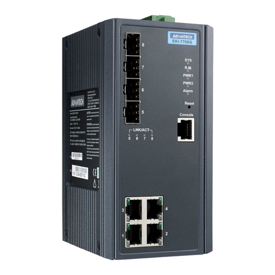
Page 17: Hardware Views
See “System LED Panel” on page 6 for further details. Reset button Button allows for system soft reset or factory default reset. Console serial port Console cable port to COM port (DB9 male) on computer to RS232 managed switch (RJ45 female). EKI-7708 Series User Manual... -
Page 18: Figure 1.2 Front View
See “System LED Panel (only for PoE model)” on page 7 for further details. Reset button Button allows for system soft reset or factory default reset. Console serial port Console cable port to COM port (DB9 male) on computer to RS232 managed switch (RJ45 female). EKI-7708 Series User Manual... -
Page 19: Figure 1.3 System Led Panel
Powered down or not installed PWR2 Solid green Powered up Power down or not installed Alarm Solid red Defined major policies are detected Blinking Red Defined minor policies are detected Powered off or system is operating normally EKI-7708 Series User Manual... -
Page 20: Figure 1.4 System Led Panel
Power down or not installed Alarm Solid red Defined major policies are detected Blinking Red Defined minor policies are detected Powered off or system is operating normally PoE (depending Solid green PoE activated. the PoE ports) PoE non-working. EKI-7708 Series User Manual... -
Page 21: Rear View
Rear View Figure 1.5 Rear View Item Description Wall mounting holes Screw holes (x6) used in the installation of a wall mounting plate DIN-Rail mounting Mounting plate used for the installation to a standard DIN rail plate EKI-7708 Series User Manual... -
Page 22: Top View
The following view applies to EKI-7708E-4FP, EKI-7708E-4FPI, EKI-7708G-4FP, and EKI-7708G-4FPI. V2+V2- V1+V1- DC48V 1A@24V PWR2 P-Fail PWR1 Figure 1.7 Top View Item Description Ground terminal Screw terminal used to ground chassis Terminal block Connect cabling for power and alarm wiring EKI-7708 Series User Manual... -
Page 23: Switch Installation
Chapter Switch Installation... -
Page 24: Installation Guidelines
In this instruction, it will explain how to find a proper location for your Modbus Gateways, and how to connect to the network, hock up the power cable, and connect to the EKI-7708 Series. Verifying Switch Operation Before installing the device in a rack or on a wall, power on the switch to verify that the switch passes the power-on self-test (POST). -
Page 25: Figure 2.1 Installing The Din-Rail Mounting Kit
Figure 2.2 Correctly Installed DIN Rail Kit Grasp the bottom of the switch and slightly rotate it upwards. If there is resistance, the switch is correctly installed. Otherwise, re-attempt the installation process from the beginning. EKI-7708 Series User Manual... -
Page 26: Wall-Mounting
Remove the DIN mounting plate. Store the DIN mounting plate and provided screws for later use. Align the wall mounting plates on the rear side. The screw holes on the device and the mounting plates must be aligned, see the following illustration. EKI-7708 Series User Manual... -
Page 27: Figure 2.4 Installing Wall Mount Plates
Do not completely tighten the screws into the wall. A final adjust- ment may be needed before fully securing the wall mounting plates on the wall. Align the wall mount plate over the screws on the wall. EKI-7708 Series User Manual... -
Page 28: Figure 2.6 Wall Mount Installation
Install the wall mount plate on the screws and slide it forward to lock in place, see the following figure. Figure 2.6 Wall Mount Installation Once the device is installed on the wall, tighten the screws to secure the device. EKI-7708 Series User Manual... -
Page 29: Installing And Removing Sfp Modules
The Gigabit Ethernet ports on the switch are 100/1000Base SFP Fiber ports, which require using the 100M or 1G mini-GBIC fiber transceivers to work properly. Advantech provides completed transceiver models for different distance requirement. The concept behind the LC port and cable is quite straight forward. Suppose that you are connecting devices I and II;... -
Page 30: Figure 2.8 Installing An Sfp Transceiver
Insert the fiber cable into the transceiver. The connector snaps into place and locks. Figure 2.9 Attaching a Fiber Optic Cable to a Transceiver Repeat the previous procedures to install any additional SFP transceivers in the switch. The fiber port is now setup. EKI-7708 Series User Manual... -
Page 31: Removing Sfp Modules
Hold the handle on the transceiver and pull the transceiver out of the slot. Handle Figure 2.11 Removing an SFP Transceiver Note! Replace the dust plug on the slot if you are not installing a transceiver. The dust plug protects hardware from dust contamination. EKI-7708 Series User Manual... -
Page 32: Connecting The Switch To Ethernet Ports
Pin 2 Pin 6 Pin 3 Pin 3 Pin 3 Pin 1 Pin 6 Pin 6 Pin 6 Pin 2 Figure 2.12 Ethernet Plug & Connector Pin Position Maximum cable length: 100 meters (328 ft.) for 10/100/1000BaseT. EKI-7708 Series User Manual... -
Page 33: Connecting The Switch To Console Port
Figure 2.13 Serial Console Cable Figure 2.14 DB 9 Pin Position DB9 Connector RJ45 Connector 1 Orange/White 2 Orange 3 Green/White 4 Blue 5 Blue/White 6 Green 7 Brown/White 8 Brown RJ45 Female Male Figure 2.15 Pin Assignment EKI-7708 Series User Manual... -
Page 34: Power Supply Installation
48 VDC. Dual power inputs are supported and allow you to connect a backup power source. Single DC Power Redundant DC Power P2 P1 P2 P1 Chassis Chassis (pane) (pane) One DC Supply Dual DC Supplies Figure 2.16 Power Wiring for EKI-7708 Series EKI-7708 Series User Manual... -
Page 35: Considerations
Caution! Do not service equipment or cables during periods of lightning activity. Caution! Do not service any components unless qualified and authorized to do Caution! Do not block air ventilation holes. EKI-7708 Series User Manual... -
Page 36: Wiring A Relay Contact
2.7.4 Wiring a Relay Contact The following section details the wiring of the relay output. The terminal block on the EKI-7708 Series is wired and then installed onto the terminal receptor located on the EKI-7708 Series. V2+V2- V1+V1-... -
Page 37: Wiring The Power Inputs
Insert a small flat-bladed screwdriver in the V1+/V1- wire-clamp screws, and loosen the screws. Insert the negative/positive DC wires into the V+/V- terminals of PW1. If setting up power redundancy, connect PW2 in the same manner. EKI-7708 Series User Manual... -
Page 38: Reset Button
Reset Button Reset configuration to factory default: Press and hold Reset button for 5 seconds. System reboot: Press and hold Reset button for 2 seconds. Note! Do NOT power off the Ethernet switch when loading default settings. EKI-7708 Series User Manual... -
Page 39: Configuration Utility
Chapter Configuration Utility... -
Page 40: First Time Setup
Secure Shell (SSH). An SNMP interface can be used to read/write many settings. Command Line Interface (CLI) can be used to read/write most settings. Initial setup must be done using an Ethernet connection (recommended) or the serial port. EKI-7708 Series User Manual... -
Page 41: Using The Graphical (Web) Interface
NTP Server: The IP address or domain name of an NTP (Network Time Proto- col) server from which the switch may retrieve the current time at startup. Please note that using a domain name requires that at least one domain name server be configured. EKI-7708 Series User Manual... -
Page 42: Configuring The Ethernet Ports
Otherwise, the switch will use the fixed Ethernet port and the corresponding settings for it. Note! When 100f is selected for the SFP of a gigabit combination port, the cor- responding fixed Ethernet jack will be disabled unless it is changed back to 1000F. EKI-7708 Series User Manual... -
Page 43: Command Line Interface Configuration
To connect by Ethernet, open a command prompt window and type: telnet <switchip> (where <switchip> is the IP address of the switch) At the login prompt, type “cli” for the username and “admin” for the password. The switch will respond with “Managed switch configuration CLI ready”. EKI-7708 Series User Manual... -
Page 44: Web Browser Configuration
In the browser’s address bar, type the switch’s default IP address (192.168.1.1). The login screen displays. Enter the user default name and password (admin / admin). Click OK on the login screen to log in. The main interface displays. EKI-7708 Series User Manual... -
Page 45: Managing Switch
Chapter Managing Switch... -
Page 46: Log In
In the User Name field, enter admin for this account. It is not necessary to change the user name, however, a change in the default settings increases the security settings. In the Password field, type in the new password. Re-type the same password in the Retype Password field. EKI-7708 Series User Manual... -
Page 47: Monitoring
Location, MAC Address, Firmware version, and more, pertaining to the system. The information is for review only. To modify the device information, see the respective item within the user interface. To access this page, click Monitoring > Device Information. Figure 4.3 Monitoring > Device Information EKI-7708 Series User Manual... -
Page 48: Logging Message
Click the drop-down menu to select a target to store the log messages. Buffered: Store log messages in RAM. All log messages are cleared after system reboot. File: Store log messages in a file. EKI-7708 Series User Manual... -
Page 49: Port Monitoring
Click the drop-down menu to select a port and its captured statistical setting values. Clear Click Clear to clear the counter selections. The ensuing table for IF MIB Counters settings are informational only: ifInOctets, ifInUcastPkts, ifInNUcastPkts, ifInDiscards, ifOutOctets, ifOutUcastPkts, ifOutNUcastPkts, ifOutDiscards, ifInMulticastPkts, ifInBroadcastPkts, ifOutMulticastPkts and ifOutBroadcastPkts. EKI-7708 Series User Manual... -
Page 50: Link Aggregation
The ensuing table for Link Aggregation Group Status settings are informational only: LAG, Name, Type, Link State, Active Member and Standby Member. The ensuing table for LACP Information settings are informational only: LAG, Port, PartnerSysId, PnKey, AtKey, Sel, Mux, Receiv, PrdTx, AtState and PnState. EKI-7708 Series User Manual... -
Page 51: Lldp Statistics
Insertions, Deletions, Drops and Age Outs. The ensuing table for LLDP Port Statistics settings are informational only: Port, TX Frames (Total), RX Frames (Total, Discarded and Errors), RX TLVs (Discarded and Unrecognized) and RX Ageouts (Total). EKI-7708 Series User Manual... -
Page 52: Igmp Statistics
RX, Invalid RX, Other RX, Leave RX, Report RX, General Query RX, Special Group Query RX, Special Group & Source Query RX, Leave TX, Report TX, General Query TX, Special Group Query TX and Special Group & Source Query TX. EKI-7708 Series User Manual... -
Page 53: System
Click Apply to save the values and update the screen. The ensuing table for IP Address Information settings are informational only: DHCP State, Static IP Address, Static Subnet Mask, Static Gateway, Static DNS Server 1 and Static DNS Server 2. EKI-7708 Series User Manual... -
Page 54: Dhcp Client Option 82
The ensuing table for DHCP Client Option 82 Information table settings are informational only: Status, Circuit ID Format, Circuit ID String, Circuit ID Hex, Circuit ID User-Define, Remote ID Format, Remote ID String, Remote ID Hex and Remote ID User-Define. EKI-7708 Series User Manual... -
Page 55: Dhcp Auto Provision
Click Apply to save the values and update the screen. The ensuing table for IPv6 Information settings are informational only: Auto Configuration, IPv6 In Use Address, IPv6 In Use Router, IPv6 Static Address, IPv6 Static Router and DHCPv6 Client. EKI-7708 Series User Manual... -
Page 56: Management Vlan
Item Description Management VLAN Click the drop-down menu to select a defined VLAN. Apply Click Apply to save the values and update the screen. The ensuing table for Management VLAN State are informational only: Management VLAN. EKI-7708 Series User Manual... -
Page 57: System Time
Click the drop-down menu to select a system time zone. Daylight Saving Time Click the drop-down menu to enable or disable the daylight saving time settings. Daylight Saving Time Enter the offsetting variable in seconds to adjust for daylight saving Offset time. EKI-7708 Series User Manual... -
Page 58: L2 Switching
Click the radio-button to enable or disable the Port Setting function. Speed Click the drop-down menu to select the port speed: Auto, Auto-10M, Auto-100M, Auto-1000M, Auto-10/100M, 10M, 100M, or 1000M. Duplex Click the drop-down menu to select the duplex setting: Auto, Half or Full. EKI-7708 Series User Manual... -
Page 59: Port Mirror
Click the drop-down menu to select the destination port and receive all the traffic from configured mirrored port(s). Allow-ingress Click the drop-down menu to enable or disable the Allow-ingress function. Sniffer RX Ports Enter the variable to define the RX port. EKI-7708 Series User Manual... -
Page 60: Link Aggregation
Layer 2 Bridging. Link aggregation allows for the logical merging of multiple ports into a single link. To access this page, click L2 Switching > Link Aggregation > LAG Management. Figure 4.18 L2 Switching > Link Aggregation > LAG Management EKI-7708 Series User Manual... -
Page 61: Figure 4.19 L2 Switching > Link Aggregation > Lag Port Settings
Click Apply to save the values and update the screen. The ensuing table for LAG Port Status settings are informational only: LAG, Description, Port Type, Enable State, Link Status, Speed, Duplex, FlowCtrl Config and FlowCtrl Status. EKI-7708 Series User Manual... -
Page 62: Figure 4.20 L2 Switching > Link Aggregation > Lacp Priority Settings
Click the radio button to select the setting mode: Active or Passive. Active: Enables LACP unconditionally. Passive: Enables LACP only when an LACP device is detected (default state). Apply Click Apply to save the values and update the screen. EKI-7708 Series User Manual... -
Page 63: Q Vlan
Enter the prefix to be used by the VLAN list entry in the previous field. Prefix Apply Click Apply to save the values and update the screen. The ensuing table for VLAN Table settings are informational only: VLAN ID, VLAN Name, VLAN Type and Edit (click to enter VLAN name). EKI-7708 Series User Manual... -
Page 64: Figure 4.23 L2 Switching > 802.1Q Vlan > Pvid Settings
The default is Disabled. Apply Click Apply to save the values and update the screen. The ensuing table for Port VLAN Status settings are informational only: Port, Interface VLAN Mode, PVID, Accept Frame Type and Ingress Filtering. EKI-7708 Series User Manual... -
Page 65: Figure 4.24 L2 Switching > 802.1Q Vlan > Port To Vlan
Trunk: Port hybrid model. Tunnel: Port hybrid model. Membership Displays the assigned membership status of the port entry, options include: Forbidden, Excluded Tagged or Untagged. Apply Click Apply to save the values and update the screen. EKI-7708 Series User Manual... -
Page 66: Q-In-Q
Enter the outer VLAN handled by the switch giving the attached Ethertype machine a single-tagged 802.1Q VLAN frame. Apply Click Apply to save the values and update the screen. The ensuing table for QinQ Global Information settings are informational only: Outer VLAN Ethertype. EKI-7708 Series User Manual... -
Page 67: Figure 4.26 L2 Switching > Q-In-Q > Port Settings
NNI: Selects a network-to-network interface which specifies communication between two specified networks. Apply Click Apply to save the values and update the screen. The ensuing table for QinQ Port Information settings are informational only: Port, Outer PVID and Outer Mode. EKI-7708 Series User Manual... -
Page 68: Garp
12 and 12000. An instance of this timer exists for each GARP participant for each port. Apply Click Apply to save the values and update the screen. The ensuing table for GARP Information settings are informational only: Join Time, Leave Time and Leave All Time. EKI-7708 Series User Manual... -
Page 69: Figure 4.28 L2 Switching > Garp > Gvrp Settings
Click Apply to save the values and update the screen. The ensuing table for GMRP Information settings are informational only: GMRP. The ensuing table for Multicast Groups settings are informational only: VLAN ID, MAC Address, Type and Member Ports. EKI-7708 Series User Manual... -
Page 70: Az Eee
The Multicast Filtering page allows for the definition of action settings when an unknown multicast request is received. The options include: Drop, Flood, or Router Port. To access this page, click L2 Switching > Multicast > Multicast Filtering. Figure 4.31 L2 Switching > Multicast > Multicast Filtering EKI-7708 Series User Manual... -
Page 71: Figure 4.32 L2 Switching > Multicast > Igmp Snooping > Igmp Settings
No., VLAN ID, IGMP Snooping Operation State, Router Ports Auto Learn, Query Robustness, Query Interval (sec.), Query Max Response Interval (sec.), Last Member Query count, Last Member Query Interval (sec), Immediate Leave and Edit (click to modify the settings). EKI-7708 Series User Manual... -
Page 72: Figure 4.33 L2 Switching > Multicast > Igmp Snooping > Igmp Querier
Enter the port numbers to associate with the static group. Click Add to add an IGMP group. The ensuing table for IGMP Static Groups Status settings are informational only: VLAN ID, Group IP Address, Member Ports and Modify. EKI-7708 Series User Manual... -
Page 73: Figure 4.35 L2 Switching > Multicast > Mld Snooping > Mld Settings
No., VLAN ID, MLD Snooping Operation State, Router Ports Auto Learn, Query Robustness, Query Interval (sec.), Query Max Response Interval (sec.), Last Member Query count, Last Member Query Interval (sec), Immediate Leave and Edit (click to modify the settings). EKI-7708 Series User Manual... -
Page 74: Figure 4.36 L2 Switching > Multicast > Mld Snooping > Mld Querier
Enter the VLAN ID to define the local MLD Static Group. Group IP Address Enter the IP address associated with the static group. Member Ports Enter the ports designated with the static group. Click Add to add a MLD static group. EKI-7708 Series User Manual... -
Page 75: Jumbo Frame
Enter the variable in bytes (1518 to 9216) to define the jumbo frame (Bytes) size. Apply Click Apply to save the values and update the screen. The ensuing table for Jumbo Frame Config settings are informational only: Jumbo Frame (Bytes). EKI-7708 Series User Manual... -
Page 76: Spanning Tree
RSTP-Operation: 802.1w operation. MSTP-Operation: 802.1s operation. Apply Click Apply to save the values and update the screen. The ensuing table for STP Information settings are informational only: STP, BPDU Forward, PathCost Method and Force Version. EKI-7708 Series User Manual... -
Page 77: Figure 4.40 L2 Switching > Spanning Tree > Stp Port Settings
BPDU formats. Apply Click Apply to save the values and update the screen. The ensuing table for STP Port Status settings are informational only: Port, Admin Enable, Path Cost, Edge Port and P2P MAC. EKI-7708 Series User Manual... -
Page 78: Figure 4.41 L2 Switching > Spanning Tree > Stp Bridge Settings
Priority, Forward Delay, Max Age, Tx Hold Count and Hello Time. The ensuing table for STP Bridge Status settings are informational only: Bridge Identifier, Designated Root Bridge, Root Path Cost, Designated Bridge, Root Port and Last Topology Change. EKI-7708 Series User Manual... -
Page 79: Figure 4.42 L2 Switching > Spanning Tree > Stp Port Advanced Settings
Enter the identifier for the Revision Configuration, range: 0 to 65535 (default: 0). Apply Click Apply to save the values and update the screen. The ensuing table for MST Configuration Identification Information settings are informational only: Configuration Name and Revision Level. EKI-7708 Series User Manual... -
Page 80: Figure 4.44 L2 Switching > Spanning Tree > Mst Instance Id Settings
Click the drop-down menu set the bridge priority in the specified MST instance Apply Click Apply to save the values and update the screen. The ensuing table for MST Instance Priority Information settings are informational only: MSTI ID, Priority and Action. EKI-7708 Series User Manual... -
Page 81: X-Ring Elite
Item Description State Select Enabled or Disabled to setup the X-Ring Elite mode. Apply Click Apply to save the values and update the screen. The ensuing table for Information settings are informational only: X-Ring Elite State. EKI-7708 Series User Manual... -
Page 82: X-Ring Pro
Item Description State Select Enabled or Disabled to setup the X-Ring Pro mode. Apply Click Apply to save the values and update the screen. The ensuing table for Information settings are informational only: X-Ring Pro State. EKI-7708 Series User Manual... -
Page 83: Figure 4.49 L2 Switching > X-Ring Pro > X-Ring Pro Groups > X-Ring Pro Groups Settings
Figure 4.51 L2 Switching > X-Ring Pro > X-Ring Pro Groups > Couple Setting The following table describes the items in the previous figure. Item Description Couple Ring ID Enter a number to specifies a ranging from 1 to 255 to identify a given X-Ring group. EKI-7708 Series User Manual... -
Page 84: Figure 4.52 L2 Switching > X-Ring Pro > X-Ring Pro Groups > Pair Settings
Click Add to save the values and update the screen. The ensuing table for Information settings are informational only: Ring ID, Mode, Operation State, Port 1, Forwarding State, Port 2, Forwarding State and Delete (click to delete the desired Ring ID). EKI-7708 Series User Manual... -
Page 85: Loopback Detection
To access this page, click L2 Switching > Loopback Detection > Port Settings. Figure 4.55 L2 Switching > Loopback Detection > Port Settings The following table describes the items in the previous figure. Item Description Port Select Enter the port to define the local loopback detection setting. EKI-7708 Series User Manual... -
Page 86: Cfm
Click the drop down menu to select the ME group level. Apply Click Apply to save the values and update the screen. The ensuing table for Information settings are informational only: Group, Level and Delete (Click Delete to delete the desired ME group). EKI-7708 Series User Manual... -
Page 87: Erps
Click Apply to save the values and update the screen. The ensuing table for Information settings are informational only: ERPS State. 4.5.15.2 MR Groups To access this page, click L2 Switching > ERPS > ERPS Groups. Figure 4.60 L2 Switching > ERPS > ERPS Groups EKI-7708 Series User Manual... -
Page 88: Mac Address Table
Apply Click Apply to save the values and update the screen. The ensuing table for Static MAC Status settings are informational only: No., MAC Address, VLAN, Port and Delete (click to delete the desired MAC address). EKI-7708 Series User Manual... -
Page 89: Mac Aging Time
Click the drop-down menu to select the VLAN to show or clear dynamic MAC entries. MAC Address Enter the MAC address to show or clear dynamic MAC entries. If a port, VLAN or MAC address is not selected the whole dynamic MAC table is displayed or cleared. EKI-7708 Series User Manual... -
Page 90: Security
Included: include preamble & IFG (20 bytes) when count ingress storm control rate. Apply Click Apply to save the values and update the screen. The ensuing table for Storm Control Global Information settings are informational only: Unit and Preamble & IFG. EKI-7708 Series User Manual... -
Page 91: Figure 4.65 Security > Storm Control > Port Settings
Apply Click Apply to save the values and update the screen. The ensuing table for Storm Control Port Information settings are informational only: Port, Port State, Broadcast (Kbps), Unknown Multicast (Kbps), Unknown Unicast (Kbps) and Action. EKI-7708 Series User Manual... -
Page 92: Port Security
Select Unprotected or Protected to define the port type. Apply Click Apply to save the values and update the screen. The ensuing table for Protected Ports Status settings are informational only: Protected Ports and Unprotected Ports. EKI-7708 Series User Manual... -
Page 93: Dos Prevention
The following table describes the items in the previous figure. Item Description DMAC = SMAC Click Enabled or Disabled to define DMAC-SMAC for the DoS Global settings. LAND Click Enabled or Disabled to define LAND for the DoS Global settings. EKI-7708 Series User Manual... -
Page 94: Figure 4.69 Security > Dos Prevention > Dos Port Settings
The DoS Port Settings page allow you to configure DoS security (enabled or disabled) for the selected port. To access this page, click Security > DoS Prevention > DoS Port Settings. Figure 4.69 Security > DoS Prevention > DoS Port Settings EKI-7708 Series User Manual... -
Page 95: Applications
Service and Current Telnet Sessions Count. 4.7.5.2 Secure Shell (SSH) is a protocol providing secure (encrypted) management connection to a remote device. To access this page, click Security > Applications > SSH. Figure 4.71 Security > Applications > SSH EKI-7708 Series User Manual... -
Page 96: Figure 4.72 Security > Applications > Http
To access this page, click Security > Applications > HTTPS. Figure 4.73 Security > Applications > HTTPS The following table describes the items in the previous figure. Item Description HTTPS Service Click Enabled or Disabled to set up Ethernet encapsulation over HTTPS. EKI-7708 Series User Manual... -
Page 97: Figure 4.74 Security > 802.1X > 802.1X Settings
Apply Click Apply to save the values and update the screen. The ensuing table for 802.1x Information settings are informational only: 802.1x State, Server IP, Server Port, Accounting Port, Security Key and Reauth Period. EKI-7708 Series User Manual... -
Page 98: Ip Security
Click Enabled or Disabled to define the global setting for the IP security function. Apply Click Apply to save the values and update the screen. The ensuing table for IP Security Status settings are informational only: IP Security. EKI-7708 Series User Manual... -
Page 99: Figure 4.77 Security > Ip Security > Entry Settings
Enter the type of services to associate with the entry setting. Apply Click Apply to save the values and update the screen. The ensuing table for IP Security Entry Information settings are informational only: IP Address, IP Mask, Services and Action. EKI-7708 Series User Manual... -
Page 100: Access Control List
Click the drop down menu to select the MAC ACL action. Options include: Permit or Drop. Status Click the drop down menu to select the MAC ACL status. Options include: Active or Inactive. Click Add to add a MAC ACL entry. EKI-7708 Series User Manual... -
Page 101: Figure 4.79 Security > Access Control List > Ip Acl > Entry Settings
Enter a value to specify the L4 source port. Portlist Select the port to configure for the IP ACL function. Action Click the drop down menu to select the IP ACL action. Options include: Permit or Drop. EKI-7708 Series User Manual... -
Page 102: Ip Source Guard
Enter the MAC address to set source MAC address. Address Source IP Address Enter the IP address to set source IP address. Port Select the port to configure for the IP source guard. Click Add to add an IP source guard. EKI-7708 Series User Manual... -
Page 103: Dhcp Snooping
Enabled Click Enabled or Disabled to enable DHCP Snooping port. Apply Click Apply to save the values and update the screen. Figure 4.84 Security > DHCP Snooping > Global Settings > DHCP Snooping Binding Port Settings EKI-7708 Series User Manual... -
Page 104: Arp Spoofing
Address Source IP Address Enter the IP address to set source IP address. Click Add to add an ARP spoofing. The ensuing table for Entry Information settings are informational only: Source MAC, Source IP and Modify. EKI-7708 Series User Manual... -
Page 105: Qos
Description QoS Mode Select Disabled or Basic to setup the QoS function. Apply Click Apply to save the values and update the screen. The ensuing table for QoS Global Information settings are informational only: QoS Mode. EKI-7708 Series User Manual... -
Page 106: Figure 4.87 Qos > General > Qos Settings
Precedence the QoS function. Apply Click Apply to save the values and update the screen. The ensuing table for QoS Status settings are informational only: Port, CoS value, Remark CoS, Remark DSCP and Remark IP Precedence. EKI-7708 Series User Manual... -
Page 107: Figure 4.88 Qos > General > Qos Scheduling
% of WRR Bandwidth Displays the allotted bandwidth for the queue entry in percentage values. Apply Click Apply to save the values and update the screen. The ensuing table for Queue Information settings are informational only: Strict Priority Queue Number. EKI-7708 Series User Manual... -
Page 108: Figure 4.89 Qos > General > Cos Mapping
Click Apply to save the values and update the screen. The ensuing table for CoS Mapping Information settings are informational only: CoS and Mapping to Queue. The ensuing table for Queue Mapping Information settings are informational only: Queue and Mapping to CoS. EKI-7708 Series User Manual... -
Page 109: Figure 4.90 Qos > General > Dscp Mapping
Click Apply to save the values and update the screen. The ensuing table for DSCP Mapping Information settings are informational only: DSCP and Mapping to Queue. The ensuing table for Queue Mapping Information settings are informational only: Queue and Mapping to DSCP. EKI-7708 Series User Manual... -
Page 110: Figure 4.91 Qos > General > Ip Precedence Mapping
Click Apply to save the values and update the screen. The ensuing table for IP Precedence Mapping Information settings are informational only: IP Precedence and Mapping to Queue. The ensuing table for Queue Mapping Information settings are informational only: Queue and Mapping to IP Precedence. EKI-7708 Series User Manual... -
Page 111: Qos Basic Mode
Select Enabled or Disabled to set the port’s trust state status. Apply Click Apply to save the values and update the screen. The ensuing table for QoS Port Status settings are informational only: Port and Trust State. EKI-7708 Series User Manual... -
Page 112: Rate Limit
To access this page, click QoS > Rate Limit > Egress Bandwidth Control. Figure 4.95 QoS > Rate Limit > Egress Bandwidth Control The following table describes the items in the previous figure. Item Description Port Enter the port number to set the Egress Bandwidth Control. EKI-7708 Series User Manual... -
Page 113: Figure 4.96 Qos > Rate Limit > Egress Queue
Enter the value in Kbps (16 to 1000000) to set the CIR rate for the Egress queue. Apply Click Apply to save the values and update the screen. The ensuing table for FE1 Egress Per Queue Status settings are informational only: Queue Id and Egress Rate Limit (Kbps). EKI-7708 Series User Manual... -
Page 114: Bandwidth Guarantee
The ensuing table for Ingress Bandwidth Control Status settings are informational only: Status, Guarantee Bandwidth, Guarantee Type, UDP Source Port and Force Mode. 4.8.4.2 Utilzation To access this page, click QoS > Bandwidth Guarantee > Utilzation. Figure 4.98 QoS > Bandwidth Guarantee > Utilzation EKI-7708 Series User Manual... -
Page 115: Management
Click Apply to save the values and update the screen. The ensuing table for LLDP Global Config settings are informational only: LLDP Enabled, LLDP PDU Disable Action, Transmission Interval, Holdtime Multiplier, Reinitialization Delay and Transmit Delay. EKI-7708 Series User Manual... -
Page 116: Figure 4.100 Management > Lldp > Lldp Port Settings > Lldp Port Configuration
System Capability: To include system capability TLV in LLDP frames. 802.3 MAC-PHY: 802.3 Link Aggregation: 802.3 Maximum Frame Size: Management Address: 802.1 PVID: Apply Click Apply to save the values and update the screen. EKI-7708 Series User Manual... -
Page 117: Figure 4.102 Management > Lldp > Lldp Port Settings > Vlan Name Tlv Vlan Selection
Chassis ID Subtype, Chassis ID, System Name, System Description, Capabilities Supported, Capabilities Enabled and Port ID Subtype. The ensuing table for Port Status settings are informational only: Port, Selected VLAN and Detail (click the radio box and click Detail to displays the details). EKI-7708 Series User Manual... -
Page 118: Figure 4.104 Management > Lldp > Lldp Remote Device Info
Figure 4.105 Management > LLDP > LLDP Overloading The ensuing table for LLDP Overloading settings are informational only: Port, Total (Bytes), Left to Send (Bytes), Status and Status (Mandatory TLVs, 802.3 TLVs, Optional TLVs and 802.1 TLVs). EKI-7708 Series User Manual... -
Page 119: Snmp
Click the radio box to specify the access level (read only or read write) Apply Click Apply to save the values and update the screen. The ensuing table for Community Status settings are informational only: No., Community Name, Access Right and Delete (click to delete the desired community name). EKI-7708 Series User Manual... -
Page 120: Figure 4.108 Management > Snmp > Snmpv3 Settings
Click Add to save the values and update the screen. The ensuing table for User Status settings are informational only: User Name, Access Right, Auth-Protocol, Priv-Protocol and Delete (click to delete the desired user name). EKI-7708 Series User Manual... -
Page 121: Power Over Ethernet
AC power is not readily available. Power over Ethernet can be used for the following areas: Surveillance devices I/O sensors for security requirements Wireless access points Series Supported Models EKI-7708E-4FP, EKI-7708E-4FPI, EKI-7708G-4FP, and EKI-7708G- 4FPI EKI-7708 Series User Manual... -
Page 122: Figure 4.110 Management > Power Over Ethernet > Poe System Settings
The PoE Port Settings page allows you to configure the port status, its power limitations, legacy mode status, and power limit settings. To access this page, click Management > Power Over Ethernet > PoE Port Settings. Figure 4.111 Management > Power Over Ethernet > PoE Port Settings EKI-7708 Series User Manual... -
Page 123: Tcp Modbus Settings
Enter the value (1 to 86400) to define the timeout period between transport time. Apply Click Apply to save the values and update the screen. The ensuing table for TCP Modbus Status settings are informational only: TCP Modbus status and TCP Modbus time out. EKI-7708 Series User Manual... -
Page 124: Dhcp Server
The Global Settings page allows you to configure the global settings for the DHCP function. To access this page, click Management > DHCP Server > Global Settings. Figure 4.114 Management > DHCP Server > Global Settings EKI-7708 Series User Manual... -
Page 125: Figure 4.115 Management > Dhcp Server > Port Settings
Click Apply to save the values and update the screen. The ensuing table for Port Information settings are informational only: Port, Low IP Address, High IP Address, Subnet Mask, Gateway, DNS, Edit (click to modify the settings) and Clear (click to clear the settings). EKI-7708 Series User Manual... -
Page 126: Figure 4.116 Management > Dhcp Server > Option 82 Settings
The ensuing table for Entry Information settings are informational only: Entry (click the drop-down menu to select an entry), Entry ID, Circuit ID Format, Circuit ID Content, Remote ID Format, Remote ID Content, Low IP Address, High IP Address, EKI-7708 Series User Manual... -
Page 127: Figure 4.117 Management > Dhcp Server > Client Mac Settings
To access this page, click Management > DHCP Server > Lease Entry. Figure 4.118 Management > DHCP Server > Lease Entry The ensuing table for Lease entry Table settings are informational only: IP Address, Client Mac, Start Time, End Time and Type. EKI-7708 Series User Manual... -
Page 128: Smtp Client
Server Port Enter the port number to designate the port associated with the server IP address. Sender Mail Enter the email address of the sender client. Apply Click Apply to save the values and update the screen. EKI-7708 Series User Manual... -
Page 129: Figure 4.121 Management > Smtp Client > Profile Settings > Profile Target Mail Settings
The following table describes the items in the previous figure. Item Description Title Assign the title of the email. The maximum length is 20 characters (alphanumeric, symbols (. (dot), _ (underline), - (dash line) and space). EKI-7708 Series User Manual... -
Page 130: Rmon
Click Apply to save the values and update the screen. The ensuing table for Statistics Information settings are informational only: Index, Port, Drop Events, Octets, Packets, Broadcast, Multicast, Owner and Delete (click to delete the desired index). EKI-7708 Series User Manual... -
Page 131: Figure 4.124 Management > Rmon > Rmon History
Enter the name of the owner of the RMON history group. Apply Click Apply to save the values and update the screen. The ensuing table for History Information settings are informational only: Index, Port, Buckets Requested, Interval, Owner and Delete (click to delete the desired index). EKI-7708 Series User Manual... -
Page 132: Figure 4.125 Management > Rmon > Rmon Alarm
Click Apply to save the values and update the screen. The ensuing table for Alarm Information settings are informational only: Index, Interval, Variable, Sample Type, Rising Threshold, Falling Threshold, Rising Event Index, Falling Event Index, Owner and Delete (click to delete the desired index). EKI-7708 Series User Manual... -
Page 133: Diagnostics
Through the Diagnostics function configuration of settings for the switch diagnostics is available. 4.10.1 Cable Diagnostics The Cable Diagnostics page allows you to select the port for applying a copper test. To access this page, click Diagnostics > Cable Diagnostics. Figure 4.127 Diagnostics > Cable Diagnostics EKI-7708 Series User Manual... -
Page 134: Ping Test
Interval (in sec) Enter the interval between ping packets in seconds. The default value is 1. The value ranges from 1 to 5. The interval entered is not retained across a power cycle. EKI-7708 Series User Manual... -
Page 135: Ipv6 Ping Test
Click Apply to display ping result for the IP address. 4.10.3 IPv6 Ping Test The IPv6 Ping Test page allows you to configure the Ping Test for IPv6. To access this page, click Diagnostics > IPv6 Ping Test. Figure 4.129 Diagnostics > IPv6 Ping Test EKI-7708 Series User Manual... -
Page 136: System Log
Figure 4.130 Diagnostics > System Log > Logging Service The following table describes the items in the previous figure. Item Description Logging Service Click Enabled or Disabled to set the Logging Service status. Apply Click Apply to save the values and update the screen. EKI-7708 Series User Manual... -
Page 137: Figure 4.131 Diagnostics > System Log > Local Logging
Indicates debug-level messages Apply Click Apply to save the values and update the screen. The ensuing table for Local Logging Settings Status settings are informational only: Status, Target, Severity and Delete (click to delete the desired target). EKI-7708 Series User Manual... -
Page 138: Figure 4.132 Diagnostics > System Log > System Log Server
Click Apply to save the values and update the screen. The ensuing table for Remote Logging Setting Status settings are informational only: Status, Server Info, Severity, Facility and Delete (click to delete the desired server address). EKI-7708 Series User Manual... -
Page 139: Ddm
Click Apply to save the values and update the screen. The ensuing table for Vendor Info settings are informational only: Refresh (click to reload the vendor information), Port, Connector, Speed, VendorName, VendorOui, VendorPn, VendorRev, VendorSn and DateCode. EKI-7708 Series User Manual... -
Page 140: Tools
Displays the device’s IP MAC address. Firmware Version Displays the device’s firmware version. System Indicator Displays the device’s system indicator. Previous Click Previous to back to previous page. Next Click Next to go to next page. EKI-7708 Series User Manual... -
Page 141: Backup Manager
Click a type to define the backup method: image: running configura- tion, startup configuration, custom configuration, flash log, or buffered log. Image Click the format for the image type: EKI-7708E-4F-AE-1-01-01.hex (Active) or EKI-7708E-4F-AE-1-00-97.hex (Backup). Backup Click Backup to backup the settings. EKI-7708 Series User Manual... -
Page 142: Upgrade Manager
Click a type to define the upgrade method: image, startup configura- tion, running configuration, or custom configuration. Image Click the format for the image type: EKI-7708E-4F-AE-1-01-01.hex (Active), EKI-7708E-4F-AE-1-00-97.hex (Backup), or auto. Upgrade Click Upgrade to upgrade to the current version. EKI-7708 Series User Manual... -
Page 143: Dual Image
To access this page, click Tools > User Account. Figure 4.139 Tools > User Account The following table describes the items in the previous figure. Item Description User Name Enter the name of the new user entry. EKI-7708 Series User Manual... -
Page 144: N-Key
Reset settings take effect after a system reboot. 4.11.9 Reboot Device To access this page, click Tools > Reboot Device. Click Reboot to reboot the switch. Any configuration changes you have made since the last time you issued a save will be lost. EKI-7708 Series User Manual... -
Page 145: Modbus/Tcp Mapping
4.12 Modbus/TCP Mapping The data map addresses of Advantech switches shown in the following table start from Modbus address 30001 for function code 4. In the given example, the address offset 0x1000 (hex) equals Modbus address 34097, while the address offset 0x1100 (hex) equals Modbus address 34353. - Page 146 Port 29 Status 1 word 16 bits HEX 0x101C 34125 Port 30 Status 1 word 16 bits HEX 0x101D 34126 Port 31 Status 1 word 16 bits HEX 0x101E 34127 Port 32 Status 1 word 16 bits HEX 0x101F 34128 EKI-7708 Series User Manual...
- Page 147 0x1202 34611 Control Port 4 Flow 1 word 16 bits HEX 0x1203 34612 Control Port 5 Flow 1 word 16 bits HEX 0x1204 34613 Control Port 6 Flow 1 word 16 bits HEX 0x1205 34614 Control EKI-7708 Series User Manual...
- Page 148 0x121C 34637 Control Port 30 Flow 1 word 16 bits HEX 0x121D 34638 Control Port 31 Flow 1 word 16 bits HEX 0x121E 34639 Control Port 32 Flow 1 word 16 bits HEX 0x121F 34640 Control EKI-7708 Series User Manual...
- Page 149 35481 Description words chars Port 20 ASCII 0x157C 35501 Description words chars Port 21 ASCII 0x1590 35521 Description words chars Port 22 ASCII 0x15A4 35541 Description words chars Port 23 ASCII 0x15B8 35561 Description words chars EKI-7708 Series User Manual...
- Page 150 Port 17 Link 1 word 16 bits HEX 0x1710 35905 Up Counter Port 18 Link 1 word 16 bits HEX 0x1711 35906 Up Counter Port 19 Link 1 word 16 bits HEX 0x1712 35907 Up Counter EKI-7708 Series User Manual...
- Page 151 0x180B 36156 Voltage Port 13 PoE 1 word 16 bits HEX 0x180C 36157 Voltage Port 14 PoE 1 word 16 bits HEX 0x180D 36158 Voltage Port 15 PoE 1 word 16 bits HEX 0x180E 36159 Voltage EKI-7708 Series User Manual...
- Page 152 0x1827 36184 Current Port 9 PoE 1 word 16 bits HEX 0x1828 36185 Current Port 10 PoE 1 word 16 bits HEX 0x1829 36186 Current Port 11 PoE 1 word 16 bits HEX 0x182A 36187 Current EKI-7708 Series User Manual...
- Page 153 0x1843 36212 Power Port 5 PoE 1 word 16 bits HEX 0x1844 36213 Power Port 6 PoE 1 word 16 bits HEX 0x1845 36214 Power Port 7 PoE 1 word 16 bits HEX 0x1846 36215 Power EKI-7708 Series User Manual...
- Page 154 Received MODBUS response: 0x0020 Port 1 PoE 1 word 16 bits HEX 0x1860 36241 Temperature Port 2 PoE 1 word 16 bits HEX 0x1861 36242 Temperature Port 3 PoE 1 word 16 bits HEX 0x1862 36243 Temperature EKI-7708 Series User Manual...
- Page 155 0x187C 36269 Temperature Port 30 PoE 1 word 16 bits HEX 0x187D 36270 Temperature Port 31 PoE 1 word 16 bits HEX 0x187E 36271 Temperature Port 32 PoE 1 word 16 bits HEX 0x187F 36272 Temperature EKI-7708 Series User Manual...
- Page 156 64 bits HEX 0x2058 38281 Packets words Port 24 Tx 64 bits HEX 0x205C 38285 Packets words Port 25 Tx 64 bits HEX 0x2060 38289 Packets words Port 26 Tx 64 bits HEX 0x2064 38293 Packets words EKI-7708 Series User Manual...
- Page 157 64 bits HEX 0x2140 38513 Packets words Port 18 Rx 64 bits HEX 0x2144 38517 Packets words Port 19 Rx 64 bits HEX 0x2148 38521 Packets words Port 20 Rx 64 bits HEX 0x214C 38525 Packets words EKI-7708 Series User Manual...
- Page 158 Error Packets words Port 13 Tx 32 bits HEX 0x2218 38729 Error Packets words Port 14 Tx 32 bits HEX 0x221A 38731 Error Packets words Port 15 Tx 32 bits HEX 0x221C 38733 Error Packets words EKI-7708 Series User Manual...
- Page 159 Error Packets words Port 8 Rx 32 bits HEX 0x230E 38975 Error Packets words Port 9 Rx 32 bits HEX 0x2310 38977 Error Packets words Port 10 Rx 32 bits HEX 0x2312 38979 Error Packets words EKI-7708 Series User Manual...
- Page 160 Error Packets words Port 30 Rx 32 bits HEX 0x233A 39019 Error Packets words Port 31 Rx 32 bits HEX 0x233C 39021 Error Packets words Port 32 Rx 32 bits HEX 0x233E 39023 Error Packets words EKI-7708 Series User Manual...
-
Page 161: Troubleshooting
Chapter Troubleshooting... -
Page 162: Troubleshooting
If the LED indicators are normal and the connected cables are correct but pack- ets still cannot be transmitted, please check the user system's Ethernet device configuration or status. EKI-7708 Series User Manual... - Page 163 No part of this publication may be reproduced in any form or by any means, electronic, photocopying, recording or otherwise, without prior written permis- sion of the publisher. All brand and product names are trademarks or registered trademarks of their respective companies. © Advantech Co., Ltd. 2018...
Need help?
Do you have a question about the EKI-7708 Series and is the answer not in the manual?
Questions and answers