
Subscribe to Our Youtube Channel
Related Manuals for Advantech EKI-7428 Series


Summary of Contents for Advantech EKI-7428 Series
- Page 1 User Manual EKI-7428 Series 24GE+4G Combo/24GE PoE+4G Combo Port L2 Managed Switch...
- Page 2 No part of this manual may be reproduced, copied, translated or transmitted in any form or by any means without the prior written permission of Advantech Co., Ltd. Information provided in this manual is intended to be accurate and reliable.
- Page 3 Technical Support and Assistance Visit the Advantech web site at www.advantech.com/support where you can find the latest information about the product. Contact your distributor, sales representative, or Advantech's customer service center for technical support if you need additional assistance.
- Page 4 Before setting up the system, check that the items listed below are included and in good condition. If any item does not accord with the table, please contact your dealer immediately. 1 x L2 Managed Switch 1 x DIN-Rail mounting Bracket and Screws 1 x Wall-mounting Bracket EKI-7428 Series User Manual...
- Page 5 The sound pressure level at the operator's position according to IEC 704-1:1982 is no more than 70 dB (A). DISCLAIMER: This set of instructions is given according to IEC 704-1. Advantech disclaims all responsibility for the accuracy of any statements contained herein. EKI-7428 Series User Manual...
- Page 6 Der arbeitsplatzbezogene Schalldruckpegel nach DIN 45 635 Teil 1000 beträgt 70dB(A) oder weiger. Haftungsausschluss: Die Bedienungsanleitungen wurden entsprechend der IEC-704-1 erstellt. Advantech lehnt jegliche Verantwortung für die Richtigkeit der in diesem Zusammenhang getätigten Aussagen ab. EKI-7428 Series User Manual...
- Page 7 Always disconnect the power from the device before servicing it. Before plugging a cable into any port, discharge the voltage stored on the cable by touching the electrical contacts to the ground surface. EKI-7428 Series User Manual...
-
Page 8: Table Of Contents
System Login ................27 Chapter Managing Switch .......28 Log In ...................... 29 Recommended Practices ................ 29 4.2.1 Changing Default Password ............29 Monitoring ....................30 4.3.1 Device Information ..............30 4.3.2 Logging Message................ 31 4.3.3 Port Monitoring................32 viii EKI-7428 Series User Manual... - Page 9 Power Over Ethernet ..............101 4.9.4 TCP Modbus................103 4.9.5 DHCP Server ................103 4.9.6 SMTP Client................108 4.9.7 RMON..................110 4.10 Diagnostics ................... 113 4.10.1 Cable Diagnostics..............113 4.10.2 Ping Test................... 114 4.10.3 IPv6 Ping Test ................115 EKI-7428 Series User Manual...
- Page 10 4.10.4 System Log ................116 4.10.5 DDM..................118 4.11 Tools ..................... 119 4.12 Modbus/TCP Mapping ................124 Chapter Troubleshooting ......143 Troubleshooting ..................144 EKI-7428 Series User Manual...
- Page 11 Serial Console Cable....................16 Figure 2.10 DB 9 Pin Position ......................16 Figure 2.11 Pin Assignment ......................16 Figure 2.12 Power Wiring for EKI-7428 Series................17 Figure 2.13 Grounding Connection ....................19 Figure 2.14 Terminal Receptor: Relay Contact ................19 Figure 2.15 Terminal Receptor: Power Input Contacts ..............
- Page 12 QoS > General > CoS Mapping................... 89 Figure 4.90 QoS > General > DSCP Mapping................90 Figure 4.91 QoS > General > IP Precedence Mapping ..............91 Figure 4.92 QoS > QoS Basic Mode > Global Settings..............92 EKI-7428 Series User Manual...
- Page 13 Tools > Backup Manager ..................120 Figure 4.134 Tools > Upgrade Manager..................121 Figure 4.135 Tools > Dual Image ....................122 Figure 4.136 Tools > User Account ....................122 Figure 4.137 Tools > N-Key ......................123 EKI-7428 Series User Manual xiii...
-
Page 14: Chapter 1 Product Overview
Chapter Product Overview... -
Page 15: Specifications
EN 61000-4-4 (EFT) Level 3 EN 61000-4-5 (Surge) Level 3 EN 61000-4-6 (CS) Level 3 EN 61000-4-8 (Magnetic Field) Level 3 Shock IEC 60068-2-27 Freefall IEC 60068-2-32 Vibration IEC 60068-2-6 Railway Track EN 50121-4 Side EKI-7428 Series User Manual... -
Page 16: Hardware Views
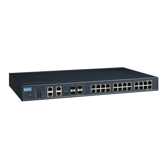
ETH port RJ45 ports x 4 SFP LEDs SFP link activity LEDs ETH port Fiber ports x 4 PoE LED Link activity LED LNK/ACT LED Green: 1000M Orange: 10/100M ETH port RJ45 ports x 24 EKI-7428 Series User Manual... -
Page 17: Figure 1.3 System Led Panel
Current link speed is 1000M. Blink green Packet transmit and receive. No link. Solid amber Current link speed is 100/10M. Blink amber Packet transmit and receive. No link. Solid green Connect to PD and supply power. EKI-7428 Series User Manual... -
Page 18: Rear View
Console cable port to COM port (DB9 male) on computer to RS232 managed switch (RJ45 female). P-Fail block An open circuit occurs upon detecting a power failure. A close circuit denotes normal power activity. Power block Connect cabling for power wiring. EKI-7428 Series User Manual... -
Page 19: Dimensions
Dimensions EKI-7428G-4CI Figure 1.6 EKI-7428G-4CI Dimensions EKI-7428G-4CPI Figure 1.7 EKI-7428G-4CPI Dimensions EKI-7428 Series User Manual... -
Page 20: Chapter 2 Switch Installation
Chapter Switch Installation... -
Page 21: Warnings
Caution! This unit may have more than one power supply connection. All connections must be removed to de-energize the unit. Caution! The installation, replacement, or service of the device must be Only be performed by trained and qualified personnel. EKI-7428 Series User Manual... - Page 22 Warning! Airflow around the switch must be unrestricted. To prevent the switch from overheating, there must be the following minimum clearances: Top and bottom: 2.0 in. (50.8 mm) Sides: 2.0 in. (50.8 mm) Front: 2.0 in. (50.8 mm) EKI-7428 Series User Manual...
-
Page 23: Installation Guidelines
Connecting Hardware In this instruction, it will explain how to find a proper location for your Modbus Gateways, and how to connect to the network, hock up the power cable, and connect to the EKI-7428 Series. EKI-7428 Series User Manual... -
Page 24: Verifying Switch Operation
Res et R.M . P-F AIL R- FA IL LO OP Te mp LIN K / LINK / ACT Spe ed LINK / ACT Spe ed LINK / ACT Spe ed Figure 2.2 Installing the Switch EKI-7428 Series User Manual... -
Page 25: Installing And Removing Sfp Modules
The Gigabit Ethernet ports on the switch are 100/1000Base SFP Fiber ports, which require using the 100M or 1G mini-GBIC fiber transceivers to work properly. Advantech provides completed transceiver models for different distance requirement. The concept behind the LC port and cable is quite straight forward. Suppose that you are connecting devices I and II;... -
Page 26: Figure 2.4 Installing An Sfp Transceiver
Insert the fiber cable into the transceiver. The connector snaps into place and locks. Figure 2.5 Attaching a Fiber Optic Cable to a Transceiver Repeat the previous procedures to install any additional SFP transceivers in the switch. The fiber port is now setup. EKI-7428 Series User Manual... -
Page 27: Removing Sfp Modules
Hold the handle on the transceiver and pull the transceiver out of the slot. Handle Figure 2.7 Removing an SFP Transceiver Note! Replace the dust plug on the slot if you are not installing a transceiver. The dust plug protects hardware from dust contamination. EKI-7428 Series User Manual... -
Page 28: Connecting The Switch To Ethernet Ports
Pin 2 Pin 6 Pin 3 Pin 3 Pin 3 Pin 1 Pin 6 Pin 6 Pin 6 Pin 2 Figure 2.8 Ethernet Plug & Connector Pin Position Maximum cable length: 100 meters (328 ft.) for 10/100/1000BaseT. EKI-7428 Series User Manual... -
Page 29: Connecting The Switch To Console Port
Figure 2.9 Serial Console Cable Figure 2.10 DB 9 Pin Position DB9 Connector RJ45 Connector 1 Orange/White 2 Orange 3 Green/White 4 Blue 5 Blue/White 6 Green 7 Brown/White 8 Brown RJ45 Female Male Figure 2.11 Pin Assignment EKI-7428 Series User Manual... -
Page 30: Power Supply Installation
Dual power inputs are supported and allow you to connect a backup power source. Single DC Power Redundant DC Power P2 P1 P2 P1 Chassis Chassis (pane) (pane) One DC Supply Dual DC Supplies Figure 2.12 Power Wiring for EKI-7428 Series EKI-7428 Series User Manual... -
Page 31: Considerations
Caution! Do not service equipment or cables during periods of lightning activity. Caution! Do not service any components unless qualified and authorized to do Caution! Do not block air ventilation holes. EKI-7428 Series User Manual... -
Page 32: Wiring A Relay Contact
2.9.4 Wiring a Relay Contact The following section details the wiring of the relay output. The terminal block on the EKI-7428 Series is wired and then installed onto the terminal receptor located on the EKI-7428 Series. P-Fail Figure 2.14 Terminal Receptor: Relay Contact The terminal receptor includes a total of six pins: two for PWR1, two for PWR2 and two for a fault circuit. -
Page 33: Wiring The Power Inputs
PW2 in the same manner. Tighten the wire-clamp screws to secure the DC wires in place. Installing Loosening Wire-clamp DC Wires Screws Securing Wire-clamp Screws Figure 2.16 Installing DC Wires in a Terminal Block EKI-7428 Series User Manual... -
Page 34: Reset Button
Reset Button Reset configuration to factory default: Press and hold Reset button for 5 seconds. System reboot: Press and hold Reset button for 3 seconds. Note! Do NOT power off the Ethernet switch when loading default settings. EKI-7428 Series User Manual... -
Page 35: Chapter 3 Configuration Utility
Chapter Configuration Utility... -
Page 36: First Time Setup
Secure Shell (SSH). An SNMP interface can be used to read/write many settings. Command Line Interface (CLI) can be used to read/write most settings. Initial setup must be done using an Ethernet connection (recommended) or the serial port. EKI-7428 Series User Manual... - Page 37 NTP Server: The IP address or domain name of an NTP (Network Time Protocol) server from which the switch may retrieve the current time at startup. Please note that using a domain name requires that at least one domain name server be configured. EKI-7428 Series User Manual...
- Page 38 Otherwise, the switch will use the fixed Ethernet port and the corresponding settings for it Note! When 100f is selected for the SFP of a gigabit combination port, the corresponding fixed Ethernet jack will be disabled unless it is changed back to 1000F. EKI-7428 Series User Manual...
-
Page 39: Command Line Interface Configuration
To connect by Ethernet, open a command prompt window and type: telnet <switchip> (where <switchip> is the IP address of the switch) At the login prompt, type “cli” for the username and “admin” for the password. The switch will respond with “Managed switch configuration CLI ready”. EKI-7428 Series User Manual... -
Page 40: Web Browser Configuration
In the browser’s address bar, type the switch’s default IP address (192.168.1.1). The login screen displays. Enter the user default name and password (admin / admin). Click OK on the login screen to log in. The main interface displays. EKI-7428 Series User Manual... -
Page 41: Chapter 4 Managing Switch
Chapter Managing Switch... -
Page 42: Log In
In the User Name field, enter admin for this account. It is not necessary to change the user name, however, a change in the default settings increases the security settings. In the Password field, type in the new password. Re-type the same password in the Retype Password field. EKI-7428 Series User Manual... -
Page 43: Monitoring
To access this page, click Monitoring > Device Information. Figure 4.3 Monitoring > Device Information The following table describes the items in the previous figure. Item Description System Name Click Switch to enter the system name: up to 128 alphanumeric characters (default is Switch). EKI-7428 Series User Manual... -
Page 44: Logging Message
Indicates action must be taken immediately. crit: Indicates critical conditions. error: Indicates error conditions. warning: Indicates warning conditions. notice: Indicates normal but significant conditions. info: Indicates informational messages. debug: Indicates debug-level messages. EKI-7428 Series User Manual... -
Page 45: Port Monitoring
The ensuing table for Rmon MIB Counters settings are informational only: etherStatsDropEvents, etherStatsOctets, etherStatsPkts, etherStatsBroadcastPkts, etherStatsMulticastPkts, etherStatsCRCAlignErrors, etherStatsUnderSizePkts, etherStatsOverSizePkts, etherStatsFragments, etherStatsJabbers, etherStatsCollisions, etherStatsPkts64Octets, etherStatsPkts65to127Octets, etherStatsPkts128to255Octets, etherStatsPkts256to511Octets, etherStatsPkts512to1023Octets and etherStatsPkts1024to1518Octets. EKI-7428 Series User Manual... -
Page 46: Link Aggregation
Click Refresh to update the data on the screen with the present state of the data in the switch. The ensuing table for LLDP Global Statistics settings are informational only: Insertions, Deletions, Drops and Age Outs. EKI-7428 Series User Manual... -
Page 47: Igmp Statistics
RX, Invalid RX, Other RX, Leave RX, Report RX, General Query RX, Special Group Query RX, Special Group & Source Query RX, Leave TX, Report TX, General Query TX, Special Group Query TX and Special Group & Source Query TX. EKI-7428 Series User Manual... -
Page 48: System
Click Apply to save the values and update the screen. The ensuing table for IP Address Information settings are informational only: DHCP State, Static IP Address, Static Subnet Mask, Static Gateway, Static DNS Server 1 and Static DNS Server 2. EKI-7428 Series User Manual... -
Page 49: Dhcp Client Option 82
The ensuing table for DHCP Client Option 82 Information table settings are informational only: Status, Circuit ID Format, Circuit ID String, Circuit ID Hex, Circuit ID User-Define, Remote ID Format, Remote ID String, Remote ID Hex and Remote ID User-Define. EKI-7428 Series User Manual... -
Page 50: Dhcp Auto Provision
Click Apply to save the values and update the screen. The ensuing table for IPv6 Information settings are informational only: Auto Configuration, IPv6 In Use Address, IPv6 In Use Router, IPv6 Static Address, IPv6 Static Router and DHCPv6 Client. EKI-7428 Series User Manual... -
Page 51: Management Vlan
Click Apply to save the values and update the screen. The ensuing table for Management VLAN State are informational only: Management VLAN. 4.4.6 System Time To access this page, click System > System Time. Figure 4.14 System > System Time EKI-7428 Series User Manual... - Page 52 Click Apply to save the values and update the screen. The ensuing table for System Time Information settings are informational only: Current Date/Time, SNTP, SNTP Server Address, SNTP Server Port, Time zone, Daylight Saving Time, Daylight Saving Time Offset, From and To. EKI-7428 Series User Manual...
-
Page 53: L2 Switching
Click Apply to save the values and update the screen. The ensuing table for Port Status settings are informational only: Port, Edit (click to enter description), Enable State, Link Status, Speed, Duplex, FlowCtrl Config and FlowCtrl Status. EKI-7428 Series User Manual... -
Page 54: Port Mirror
Enter the variable to define the TX port. Apply Click Apply to save the values and update the screen. The ensuing table for Mirror Status settings are informational only: Session ID, Destination Port, Ingress State, Source TX Port and Source RX Port. EKI-7428 Series User Manual... -
Page 55: Link Aggregation
Enter an entry to specify the LAG name. Type Click the radio button to specify the type mode: Static or LACP. Ports Click the drop-down menu to select designated ports: GE1-28. Apply Click Apply to save the values and update the screen. EKI-7428 Series User Manual... -
Page 56: Figure 4.19 L2 Switching > Link Aggregation > Lag Port Settings
Figure 4.20 L2 Switching > Link Aggregation > LACP Priority Settings The following table describes the items in the previous figure. Item Description System Priority Enter the value (1-65535) to designate the LACP system priority. Apply Click Apply to save the values and update the screen. EKI-7428 Series User Manual... -
Page 57: Figure 4.21 L2 Switching > Link Aggregation > Lacp Port Settings
Passive: Enables LACP only when an LACP device is detected (default state). Apply Click Apply to save the values and update the screen. The ensuing table for LACP Port Information settings are informational only: Port Name, Priority, Timeout and Mode. EKI-7428 Series User Manual... -
Page 58: Q Vlan
The PVID Settings page allows you to designate a PVID for a selected port, define the accepted type and enable/disable the ingress filtering. To access this page, click L2 Switching > 802.1Q VLAN > PVID Settings. Figure 4.23 L2 Switching > 802.1Q VLAN > PVID Settings EKI-7428 Series User Manual... - Page 59 The default is Disabled. Apply Click Apply to save the values and update the screen. The ensuing table for Port VLAN Status settings are informational only: Port, Interface VLAN Mode, PVID, Accept Frame Type and Ingress Filtering. EKI-7428 Series User Manual...
-
Page 60: Figure 4.24 L2 Switching > 802.1Q Vlan > Port To Vlan
Trunk: Port hybrid model. Tunnel: Port hybrid model. Membership Displays the assigned membership status of the port entry, options include: Forbidden, Excluded Tagged or Untagged. Apply Click Apply to save the values and update the screen. EKI-7428 Series User Manual... -
Page 61: Q-In-Q
Enter the outer VLAN handled by the switch giving the attached Ethertype machine a single-tagged 802.1Q VLAN frame. Apply Click Apply to save the values and update the screen. The ensuing table for QinQ Global Information settings are informational only: Outer VLAN Ethertype. EKI-7428 Series User Manual... -
Page 62: Garp
The Generic Attribute Registration Protocol (GARP) is a local area network (LAN) protocol. The protocol defines procedures for the registration and de-registration of attributes (network identifiers or addresses) by end stations and switches with each other. EKI-7428 Series User Manual... -
Page 63: Figure 4.27 L2 Switching > Garp > Garp Settings
Registration Protocol or Generic VLAN Registration Protocol) protocol which facilitates control of virtual local area networks (VLANs) within a larger network. To access this page, click L2 Switching > GARP > GVRP Settings. Figure 4.28 L2 Switching > GARP > GVRP Settings EKI-7428 Series User Manual... -
Page 64: Az Eee
Port Select Enter the port to setup the EEE function. State Click Enabled or Disabled to set the state mode of the port select setting. Apply Click Apply to save the values and update the screen. EKI-7428 Series User Manual... - Page 65 The ensuing table for EEE Enable Status settings are informational only: Port and EEE State. EKI-7428 Series User Manual...
-
Page 66: Multicast
The following table describes the items in the previous figure. Item Description IGMP Snooping Select Enable or Disable to designate the IGMP Snooping State. State IGMP Snooping Select designate the IGMP Snooping Version: V2 or V3. Version EKI-7428 Series User Manual... -
Page 67: Figure 4.33 L2 Switching > Multicast > Igmp Snooping > Igmp Querier
Querier State, Querier Status, Querier Version and Querier IP. IGMP Static Groups To access this page, click L2 Switching > Multicast > IGMP Snooping > IGMP Static Groups. Figure 4.34 L2 Switching > Multicast > IGMP Snooping > IGMP Static Groups EKI-7428 Series User Manual... -
Page 68: Figure 4.35 L2 Switching > Multicast > Mld Snooping > Mld Settings
Report Suppression suppression. Apply Click Apply to save the values and update the screen. The ensuing table for MLD Snooping Information settings are informational only: MLD Snooping State, MLD Snooping Version and MLD Snooping V2 Report Suppression. EKI-7428 Series User Manual... -
Page 69: Figure 4.36 L2 Switching > Multicast > Mld Snooping > Mld Querier
The following table describes the items in the previous figure. Item Description VLAN ID Enter the VLAN ID to define the local MLD Static Group. Group IP Address Enter the IP address associated with the static group. EKI-7428 Series User Manual... -
Page 70: Jumbo Frame
Enter the variable in bytes (1518 to 9216) to define the jumbo frame (Bytes) size. Apply Click Apply to save the values and update the screen. The ensuing table for Jumbo Frame Config settings are informational only: Jumbo Frame (Bytes). EKI-7428 Series User Manual... -
Page 71: Spanning Tree
RSTP-Operation: 802.1w operation. MSTP-Operation: 802.1s operation. Apply Click Apply to save the values and update the screen. The ensuing table for STP Information settings are informational only: STP, BPDU Forward, PathCost Method and Force Version. EKI-7428 Series User Manual... -
Page 72: Figure 4.40 L2 Switching > Spanning Tree > Stp Port Settings
BPDU formats. Apply Click Apply to save the values and update the screen. The ensuing table for STP Port Status settings are informational only: Port, Admin Enable, Path Cost, Edge Port and P2P MAC. EKI-7428 Series User Manual... -
Page 73: Figure 4.41 L2 Switching > Spanning Tree > Stp Bridge Settings
The STP Port Advanced Settings page allows you to select the port list to apply this setting. To access this page, click L2 Switching > Spanning Tree > STP Port Advanced Settings. Figure 4.42 L2 Switching > Spanning Tree > STP Port Advanced Settings EKI-7428 Series User Manual... -
Page 74: Figure 4.43 L2 Switching > Spanning Tree > Mst Config Identification
The MST Instance ID Settings page allows you to edit the MSTI ID and VID List settings. To access this page, click L2 Switching > Spanning Tree > MST Instance ID Settings. Figure 4.44 L2 Switching > Spanning Tree > MST Instance ID Settings EKI-7428 Series User Manual... -
Page 75: Figure 4.45 L2 Switching > Spanning Tree > Mst Instance Priority Settings
To access this page, click L2 Switching > Spanning Tree > STP Statistics. The ensuing table for STP Statistics settings are informational only: Port, Configuration BPDUs Received, TCN BPDUs Received, Configuration BPDUs Transmitted and TCN BPDUs Transmitted. EKI-7428 Series User Manual... -
Page 76: X-Ring Elite
Click the drop-down menu to define the port designation. Click Add to save the values and update the screen. The ensuing table for Information settings are informational only: Ring ID, Role, Port 1, Port 2 and Delete (click to delete the desired Ring ID). EKI-7428 Series User Manual... -
Page 77: X-Ring Pro
Enter a number to specifies a ranging from 1 to 255 to identify a given X-Ring Pro group. Port 1 Click the drop-down menu to define the port designation. Port 2 Click the drop-down menu to define the port designation. Click Add to save the values and update the screen. EKI-7428 Series User Manual... -
Page 78: Figure 4.50 L2 Switching > X-Ring Pro > X-Ring Pro Groups > Chain Settings
Enter a number to specifies a ranging from 1 to 255 to identify a pair ring ID. Port Enter the port to assign to define the couple setting. Master Ring ID Click the drop-down menu to designate the master ring. Click Add to save the values and update the screen. EKI-7428 Series User Manual... -
Page 79: Loopback Detection
Enter the variable in seconds (1 to 32767) to set the interval at which frames are transmitted. Recover Time Enter the variable in seconds (60 to 1000000) to define the delay before recovery. Apply Click Apply to save the values and update the screen. EKI-7428 Series User Manual... -
Page 80: Cfm
The following table describes the items in the previous figure. Item Description State Click Enabled or Disabled to enable CFM settings. Apply Click Apply to save the values and update the screen. The ensuing table for Information settings are informational only: CFM State. EKI-7428 Series User Manual... -
Page 81: Erps
Group, MEG Level and Delete (Click Delete to delete the desired ME ID). 4.5.15 ERPS 4.5.15.1 ERPS Settings To access this page, click L2 Switching > ERPS > ERPS Settings. Figure 4.59 L2 Switching > ERPS > ERPS Settings EKI-7428 Series User Manual... -
Page 82: Figure 4.60 L2 Switching > Erps > Erps Groups
Click Apply to save the values and update the screen. The ensuing table for Information settings are informational only: Ring ID, Role, State, East Link, West Link, Override ME, Override VLAN and Delete (Click Delete to delete the desired Ring ID). EKI-7428 Series User Manual... -
Page 83: Mac Address Table
Enter the variable (10 to 630) to define the time required for aging. Apply Click Apply to save the values and update the screen. The ensuing table for Dynamic Address Status settings are informational only: Aging time. EKI-7428 Series User Manual... -
Page 84: Dynamic Forwarding Table
Click Clear to clear the MAC Address Information table. The ensuing table for MAC Address Information settings are informational only: MAC Address, VLAN, Type, Port and Add to Static MAC (click to add the MAC address to static MAC address list). EKI-7428 Series User Manual... -
Page 85: Security
Included: include preamble & IFG (20 bytes) when count ingress storm control rate. Apply Click Apply to save the values and update the screen. The ensuing table for Storm Control Global Information settings are informational only: Unit and Preamble & IFG. EKI-7428 Series User Manual... -
Page 86: Figure 4.65 Security > Storm Control > Port Settings
Apply Click Apply to save the values and update the screen. The ensuing table for Storm Control Port Information settings are informational only: Port, Port State, Broadcast (Kbps), Unknown Multicast (Kbps), Unknown Unicast (Kbps) and Action. EKI-7428 Series User Manual... -
Page 87: Port Security
Select Unprotected or Protected to define the port type. Apply Click Apply to save the values and update the screen. The ensuing table for Protected Ports Status settings are informational only: Protected Ports and Unprotected Ports. EKI-7428 Series User Manual... -
Page 88: Dos Prevention
The following table describes the items in the previous figure. Item Description DMAC = SMAC Click Enabled or Disabled to define DMAC-SMAC for the DoS Global settings. LAND Click Enabled or Disabled to define LAND for the DoS Global settings. EKI-7428 Series User Manual... -
Page 89: Figure 4.69 Security > Dos Prevention > Dos Port Settings
The DoS Port Settings page allow you to configure DoS security (enabled or disabled) for the selected port. To access this page, click Security > DoS Prevention > DoS Port Settings. Figure 4.69 Security > DoS Prevention > DoS Port Settings EKI-7428 Series User Manual... -
Page 90: Applications
The following table describes the items in the previous figure. Item Description SSH Service Click Enabled or Disabled to set up Ethernet encapsulation (remote access) through the Secure Shell (SSH) function. Apply Click Apply to save the values and update the screen. EKI-7428 Series User Manual... -
Page 91: Figure 4.72 Security > Applications > Http
Enter the variable in minutes (0 to 86400) to define the timeout period for the HTTP session. Apply Click Apply to save the values and update the screen. The ensuing table for HTTPS Information settings are informational only: HTTPS Service and Session Timeout. EKI-7428 Series User Manual... -
Page 92: Figure 4.74 Security > 802.1X > 802.1X Settings
Apply Click Apply to save the values and update the screen. The ensuing table for 802.1x Information settings are informational only: 802.1x State, Server IP, Server Port, Accounting Port, Security Key and Reauth Period. EKI-7428 Series User Manual... -
Page 93: Ip Security
Click Enabled or Disabled to define the global setting for the IP security function. Apply Click Apply to save the values and update the screen. The ensuing table for IP Security Status settings are informational only: IP Security. EKI-7428 Series User Manual... -
Page 94: Figure 4.77 Security > Ip Security > Entry Settings
Enter the type of services to associate with the entry setting. Apply Click Apply to save the values and update the screen. The ensuing table for IP Security Entry Information settings are informational only: IP Address, IP Mask, Services and Action. EKI-7428 Series User Manual... -
Page 95: Access Control List
Click the drop down menu to select the MAC ACL action. Options include: Permit or Drop. Status Click the drop down menu to select the MAC ACL status. Options include: Active or Inactive. Click Add to add a MAC ACL entry. EKI-7428 Series User Manual... -
Page 96: Figure 4.79 Security > Access Control List > Ip Acl > Entry Settings
Enter a value to specify the L4 source port. Portlist Select the port to configure for the IP ACL function. Action Click the drop down menu to select the IP ACL action. Options include: Permit or Drop. EKI-7428 Series User Manual... -
Page 97: Ip Source Guard
Enter the MAC address to set source MAC address. Address Source IP Address Enter the IP address to set source IP address. Port Select the port to configure for the IP source guard. Click Add to add an IP source guard. EKI-7428 Series User Manual... -
Page 98: Dhcp Snooping
Enabled Click Enabled or Disabled to enable DHCP Snooping port. Apply Click Apply to save the values and update the screen. Figure 4.84 Security > DHCP Snooping > Global Settings > DHCP Snooping Binding Port Settings EKI-7428 Series User Manual... -
Page 99: Arp Spoofing
Address Source IP Address Enter the IP address to set source IP address. Click Add to add an ARP spoofing. The ensuing table for Entry Information settings are informational only: Source MAC, Source IP and Modify. EKI-7428 Series User Manual... -
Page 100: Qos
The ensuing table for QoS Global Information settings are informational only: QoS Mode. 4.8.1.2 QoS Settings Once the QoS function is enabled, you can configure the available settings. To access this page, click QoS > General > QoS Settings. Figure 4.87 QoS > General > QoS Settings EKI-7428 Series User Manual... -
Page 101: Figure 4.88 Qos > General > Qos Scheduling
WRR scheduling prevents low-priority queues from being completely ignored during periods of high priority traffic. The WRR scheduler sends some packets from each queue in turn. To access this page, click QoS > General > QoS Scheduling. Figure 4.88 QoS > General > QoS Scheduling EKI-7428 Series User Manual... -
Page 102: Figure 4.89 Qos > General > Cos Mapping
The following table describes the items in the previous figure. Item Description CoS to Queue Mapping Class of Service Displays the CoS for the queue entry. Queue Click the drop-down menu to select the queue priority for selected Queue to CoS Mapping EKI-7428 Series User Manual... -
Page 103: Figure 4.90 Qos > General > Dscp Mapping
Click Apply to save the values and update the screen. The ensuing table for DSCP Mapping Information settings are informational only: DSCP and Mapping to Queue. The ensuing table for Queue Mapping Information settings are informational only: Queue and Mapping to DSCP. EKI-7428 Series User Manual... -
Page 104: Figure 4.91 Qos > General > Ip Precedence Mapping
Click Apply to save the values and update the screen. The ensuing table for IP Precedence Mapping Information settings are informational only: IP Precedence and Mapping to Queue. The ensuing table for Queue Mapping Information settings are informational only: Queue and Mapping to IP Precedence. EKI-7428 Series User Manual... -
Page 105: Qos Basic Mode
Select Enabled or Disabled to set the port’s trust state status. Apply Click Apply to save the values and update the screen. The ensuing table for QoS Port Status settings are informational only: Port and Trust State. EKI-7428 Series User Manual... -
Page 106: Rate Limit
To access this page, click QoS > Rate Limit > Egress Bandwidth Control. Figure 4.95 QoS > Rate Limit > Egress Bandwidth Control The following table describes the items in the previous figure. Item Description Port Enter the port number to set the Egress Bandwidth Control. EKI-7428 Series User Manual... -
Page 107: Figure 4.96 Qos > Rate Limit > Egress Queue
Enter the value in Kbps (16 to 1000000) to set the CIR rate for the Egress queue. Apply Click Apply to save the values and update the screen. The ensuing table for GE1 Egress Per Queue Status settings are informational only: Queue Id and Egress Rate Limit (Kbps). EKI-7428 Series User Manual... -
Page 108: Bandwidth Guarantee
The ensuing table for Ingress Bandwidth Control Status settings are informational only: Status, Guarantee Bandwidth, Guarantee Type, UDP Source Port and Force Mode. 4.8.4.2 Utilzation To access this page, click QoS > Bandwidth Guarantee > Utilzation. Figure 4.98 QoS > Bandwidth Guarantee > Utilzation EKI-7428 Series User Manual... -
Page 109: Management
Click Apply to save the values and update the screen. The ensuing table for LLDP Global Config settings are informational only: LLDP Enabled, LLDP PDU Disable Action, Transmission Interval, Holdtime Multiplier, Reinitialization Delay and Transmit Delay. EKI-7428 Series User Manual... -
Page 110: Figure 4.100 Management > Lldp > Lldp Port Settings > Lldp Port Configuration
802.3 Maximum Frame Size: Management Address: 802.1 PVID: Apply Click Apply to save the values and update the screen. The ensuing table for LLDP Port Status settings are informational only: Port, State and Selected Optional TLVs. EKI-7428 Series User Manual... -
Page 111: Figure 4.102 Management > Lldp > Lldp Port Settings > Vlan Name Tlv Vlan Selection
Figure 4.103 Management > LLDP > LLDP Remote Device Info The following table describes the items in the previous figure. Item Description Detail Click to display the device details. Delete Click to delete the selected devices. Refresh Click to refresh the remote device information list. EKI-7428 Series User Manual... -
Page 112: Snmp
To access this page, click Management > SNMP > SNMP Community. Figure 4.105 Management > SNMP > SNMP Community The following table describes the items in the previous figure. Item Description Community Name Enter a community name (up to 20 characters). EKI-7428 Series User Manual... -
Page 113: Figure 4.106 Management > Snmp > Snmpv3 Settings
Click Add to save the values and update the screen. The ensuing table for User Status settings are informational only: User Name, Access Right, Auth-Protocol, Priv-Protocol and Delete (click to delete the desired user name). EKI-7428 Series User Manual... -
Page 114: Power Over Ethernet
The PoE System Settings page allows you to configure the overload disconnect and the maximum available wattage. To access this page, click Management > Power Over Ethernet > PoE System Settings. Figure 4.108 Management > Power Over Ethernet > PoE System Settings EKI-7428 Series User Manual... -
Page 115: Figure 4.109 Management > Power Over Ethernet > Poe Port Settings
Powered Device (PD) Apply Click Apply to save the values and update the screen. The ensuing table for PoE Information settings are informational only: Port, Enable State, Power Limit From Classification, Priority, Legacy and Power Limit (W). EKI-7428 Series User Manual... -
Page 116: Tcp Modbus
The Status Settings page allows you to configure the DHCP server mode (enabled or disabled). To access this page, click Management > DHCP Server > Status Settings. Figure 4.111 Management > DHCP Server > Status Settings EKI-7428 Series User Manual... -
Page 117: Figure 4.112 Management > Dhcp Server > Global Settings
Click Apply to save the values and update the screen. The ensuing table for Global Information settings are informational only: Lease Time, Low IP Address, High IP Address, Subnet Mask, Gateway, DNS and Clear (click to clear IP pool). EKI-7428 Series User Manual... -
Page 118: Figure 4.113 Management > Dhcp Server > Port Settings
Click Apply to save the values and update the screen. The ensuing table for Port Information settings are informational only: Port, Low IP Address, High IP Address, Subnet Mask, Gateway, DNS, Edit (click to modify the settings) and Clear (click to clear the settings). EKI-7428 Series User Manual... -
Page 119: Figure 4.114 Management > Dhcp Server > Option 82 Settings
Entry ID, Circuit ID Format, Circuit ID Content, Remote ID Format, Remote ID Content, Low IP Address, High IP Address, Subnet Mask, Gateway, DNS, Edit (click to modify the settings) and Clear (click to clear the settings). EKI-7428 Series User Manual... -
Page 120: Figure 4.115 Management > Dhcp Server > Client Mac Settings
4.9.5.6 Lease Entry To access this page, click Management > DHCP Server > Lease Entry. The ensuing table for Lease entry Table settings are informational only: IP Address, Client Mac, Start Time, End Time and Type. EKI-7428 Series User Manual... -
Page 121: Smtp Client
Server Port Enter the port number to designate the port associated with the server IP address. Sender Mail Enter the email address of the sender client. Apply Click Apply to save the values and update the screen. EKI-7428 Series User Manual... -
Page 122: Figure 4.118 Management > Smtp Client > Profile Settings > Profile Target Mail Settings
The following table describes the items in the previous figure. Item Description Title Assign the title of the email. The maximum length is 20 characters (alphanumeric, symbols (. (dot), _ (underline), - (dash line) and space). EKI-7428 Series User Manual... -
Page 123: Rmon
Click Apply to save the values and update the screen. The ensuing table for Statistics Information settings are informational only: Index, Port, Drop Events, Octets, Packets, Broadcast, Multicast, Owner and Delete (click to delete the desired index). EKI-7428 Series User Manual... -
Page 124: Figure 4.121 Management > Rmon > Rmon History
Enter the name of the owner of the RMON history group. Apply Click Apply to save the values and update the screen. The ensuing table for History Information settings are informational only: Index, Port, Buckets Requested, Interval, Owner and Delete (click to delete the desired index). EKI-7428 Series User Manual... -
Page 125: Figure 4.122 Management > Rmon > Rmon Alarm
Click Apply to save the values and update the screen. The ensuing table for Alarm Information settings are informational only: Index, Interval, Variable, Sample Type, Rising Threshold, Falling Threshold, Rising Event Index, Falling Event Index, Owner and Delete (click to delete the desired index). EKI-7428 Series User Manual... -
Page 126: Diagnostics
Through the Diagnostics function configuration of settings for the switch diagnostics is available. 4.10.1 Cable Diagnostics The Cable Diagnostics page allows you to select the port for applying a copper test. To access this page, click Diagnostics > Cable Diagnostics. Figure 4.124 Diagnostics > Cable Diagnostics EKI-7428 Series User Manual... -
Page 127: Ping Test
Interval (in sec) Enter the interval between ping packets in seconds. The default value is 1. The value ranges from 1 to 5. The interval entered is not retained across a power cycle. EKI-7428 Series User Manual... -
Page 128: Ipv6 Ping Test
Click Apply to display ping result for the IP address. 4.10.3 IPv6 Ping Test The IPv6 Ping Test page allows you to configure the Ping Test for IPv6. To access this page, click Diagnostics > IPv6 Ping Test. Figure 4.126 Diagnostics > IPv6 Ping Test EKI-7428 Series User Manual... -
Page 129: System Log
Figure 4.127 Diagnostics > System Log > Logging Service The following table describes the items in the previous figure. Item Description Logging Service Click Enabled or Disabled to set the Logging Service status. Apply Click Apply to save the values and update the screen. EKI-7428 Series User Manual... -
Page 130: Figure 4.128 Diagnostics > System Log > Local Logging
System Log Server The System Log Server page allows you to configure the log server. To access this page, click Diagnostics > System Log > System Log Server. Figure 4.129 Diagnostics > System Log > System Log Server EKI-7428 Series User Manual... -
Page 131: Ddm
Click the drop-down menu to designate the announcement method: Disabled, SysLog, E-mail, or SNMP. Apply Click Apply to save the values and update the screen. The ensuing table for Diagnostic Alarm Information settings are informational only: Diagnostic Alarm. EKI-7428 Series User Manual... -
Page 132: Tools
Figure 4.132 Tools > IXM The following table describes the items in the previous figure. Item Description Search Field Enter criteria to search the IXM information. Displays the reference to the device number. Device Name Displays the device name. EKI-7428 Series User Manual... -
Page 133: Figure 4.133 Tools > Backup Manager
Click a type to define the backup method: image: running configuration, startup configuration, custom configuration, flash log, or buffered log. Image Click the format for the image type: EKI-7428G-4CI-AE-1-01-01.hex (Active) or EKI-7428G-4CI-AE-1-00-97.hex (Backup). Backup Click Backup to backup the settings. EKI-7428 Series User Manual... -
Page 134: Figure 4.134 Tools > Upgrade Manager
Click a type to define the upgrade method: image, startup configuration, running configuration, or custom configuration. Image Click the format for the image type: EKI-7428G-4CI-AE-1-01-01.hex (Active), EKI-7428G-4CI-AE-1-00-97.hex (Backup), or auto. Upgrade Click Upgrade to upgrade to the current version. EKI-7428 Series User Manual... -
Page 135: Figure 4.135 Tools > Dual Image
To access this page, click Tools > User Account. Figure 4.136 Tools > User Account The following table describes the items in the previous figure. Item Description User Name Enter the name of the new user entry. EKI-7428 Series User Manual... -
Page 136: Figure 4.137 Tools > N-Key
Reset settings take effect after a system reboot. 4.11.9 Reboot Device To access this page, click Tools > Reboot Device. Click Reboot to reboot the switch. Any configuration changes you have made since the last time you issued a save will be lost. EKI-7428 Series User Manual... -
Page 137: Modbus/Tcp Mapping
4.12 Modbus/TCP Mapping The data map addresses of Advantech switches shown in the following table start from Modbus address 30001 for function code 4. In the given example, the address offset 0x1000 (hex) equals Modbus address 34097, while the address offset 0x1100 (hex) equals Modbus address 34353. - Page 138 4.12.1 Modbus/TCP Mapping Table EKI-7428 Series User Manual...
- Page 139 Word 4 Hi byte = '\0' Firmware 0x020A 30523 Firmware Version words bits Version Word 0 Hi byte = major Word 0 Lo byte = minor Word 1 Hi byte = release Word 1 Lo byte = build EKI-7428 Series User Manual...
- Page 140 IP Address 2 0x0400 31025 IP Address words bits Ex: IP = 192.168.1.1 Word 0 Hi byte = 0xC0 Word 0 Lo byte = 0xA8 Word 1 Hi byte = 0x01 Word 1 Lo byte = 0x01 EKI-7428 Series User Manual...
- Page 141 Port 20 0x1013 34116 Status word bits Port 21 0x1014 34117 Status word bits Port 22 0x1015 34118 Status word bits Port 23 0x1016 34119 Status word bits Port 24 0x1017 34120 Status word bits EKI-7428 Series User Manual...
- Page 142 Port 16 0x110F 34368 Speed word bits Port 17 0x1110 34369 Speed word bits Port 18 0x1111 34370 Speed word bits Port 19 0x1112 34371 Speed word bits Port 20 0x1113 34372 Speed word bits EKI-7428 Series User Manual...
- Page 143 Flow word bits Control Port 22 0x1215 34630 Flow word bits Control Port 23 0x1216 34631 Flow word bits Control Port 24 0x1217 34632 Flow word bits Control Port 25 0x1218 34633 Flow word bits Control EKI-7428 Series User Manual...
- Page 144 35301 Description words chars Port 11 ASCII 0x14C8 35321 Description words chars Port 12 ASCII 0x14DC 35341 Description words chars Port 13 ASCII 0x14F0 35361 Description words chars Port 14 ASCII 0x1504 35381 Description words chars EKI-7428 Series User Manual...
- Page 145 Port 10 0x1709 35898 Link Up word bits Counter Port 11 Link 0x170A 35899 Up Counter word bits Port 12 0x170B 35900 Link Up word bits Counter Port 13 0x170C 35901 Link Up word bits Counter EKI-7428 Series User Manual...
- Page 146 Received MODBUS response: 0x0005 Port 1 PoE 0x1800 36145 Voltage word bits Port 2 PoE 0x1801 36146 Voltage word bits Port 3 PoE 0x1802 36147 Voltage word bits Port 4 PoE 0x1803 36148 Voltage word bits EKI-7428 Series User Manual...
- Page 147 Voltage Port 31 0x181E 36175 word bits Voltage Port 32 0x181F 36176 word bits Voltage 0x1820 ~ 36177 ~ PoE Current Current word bits 0x183F 36208 (mA) Ex: poe current = 13 Received EKI-7428 Series User Manual MODBUS response:...
- Page 148 Current Port 25 0x1838 36201 word bits Current Port 26 0x1839 36202 word bits Current Port 27 0x183A 36203 word bits Current Port 28 0x183B 36204 word bits Current Port 29 0x183C 36205 word bits Current EKI-7428 Series User Manual...
- Page 149 PoE Power word bits Port 31 0x185E 36239 PoE Power word bits Port 32 0x185F 36240 PoE Power word bits 0x1860 ~ 36241 ~ Temperatur word bits 0x187F 36272 Temperature (C) Ex: poe temperature = EKI-7428 Series User Manual Received...
- Page 150 Temperatur Port 15 0x186E 36255 word bits Temperatur Port 16 0x186F 36256 word bits Temperatur Port 17 0x1870 36257 word bits Temperatur Port 18 0x1871 36258 word bits Temperatur Port 19 0x1872 36259 word bits EKI-7428 Series User Manual Temperatur...
- Page 151 38249 Packets words bits Port 16 Tx 0x203C 38253 Packets words bits Port 17 Tx 0x2040 38257 Packets words bits Port 18 Tx 0x2044 38261 Packets words bits Port 19 Tx 0x2048 38265 Packets words bits EKI-7428 Series User Manual...
- Page 152 38481 Packets words bits Port 10 Rx 0x2124 38485 Packets words bits Port 11 Rx 0x2128 38489 Packets words bits Port 12 Rx 0x212C 38493 Packets words bits Port 13 Rx 0x2130 38497 Packets words bits EKI-7428 Series User Manual...
- Page 153 Port 3 Tx 0x2204 38709 Error words bits Packets Port 4 Tx 0x2206 38711 Error words bits Packets Port 5 Tx 0x2208 38713 Error words bits Packets Port 6 Tx 0x220A 38715 Error words bits Packets EKI-7428 Series User Manual...
- Page 154 Packets Port 32 Tx 0x223E 38767 Error words bits Packets Rx Error 0x2300 ~ 38961 ~ Rx Error Packets Packets words bits 0x233E 39023 Ex: port 1 Rx Counter Packet Amount = 11223344 Received EKI-7428 Series User Manual MODBUS response:...
- Page 155 Port 25 Rx 0x2330 39009 Error words bits Packets Port 26 Rx 0x2332 39011 Error words bits Packets Port 27 Rx 0x2334 39013 Error words bits Packets Port 28 Rx 0x2336 39015 Error words bits Packets EKI-7428 Series User Manual...
- Page 156 Chapter Troubleshooting...
-
Page 157: Chapter 5 Troubleshooting
If the LED indicators are normal and the connected cables are correct but the packets still cannot be transmitted. Please check the user system's Ethernet devices' configuration or status. EKI-7428 Series User Manual... - Page 158 EKI-7428 Series User Manual...
- Page 159 No part of this publication may be reproduced in any form or by any means, electronic, photocopying, recording or otherwise, without prior written permission of the publisher. All brand and product names are trademarks or registered trademarks of their respective companies. © Advantech Co., Ltd. 2018...
Need help?
Do you have a question about the EKI-7428 Series and is the answer not in the manual?
Questions and answers