Table of Contents
Advertisement
Quick Links
Advertisement
Table of Contents

Subscribe to Our Youtube Channel
Related Manuals for Advantech EKI-9516P-HV


Summary of Contents for Advantech EKI-9516P-HV
- Page 1 User Manual EKI-9500 Series Full Managed Ethernet Switches...
- Page 2 No part of this manual may be reproduced, copied, translated or transmitted in any form or by any means without the prior written permission of Advantech Co., Ltd. Information provided in this manual is intended to be accurate and reliable. How- ever, Advantech Co., Ltd.
-
Page 3: Declaration Of Conformity
This product has passed the CE test for environmental specifications when shielded cables are used for external wiring. We recommend the use of shielded cables. This kind of cable is available from Advantech. Please contact your local supplier for ordering information. -
Page 4: Document Feedback
Technical Support and Assistance Visit the Advantech web site at www.advantech.com/support where you can find the latest information about the product. Contact your distributor, sales representative, or Advantech's customer service center for technical support if you need additional assistance. Please have the following information ready before you call: –... -
Page 5: Safety Instructions
The sound pressure level at the operator's position according to IEC 704-1:1982 is no more than 70 dB (A). DISCLAIMER: This set of instructions is given according to IEC 704-1. Advantech disclaims all responsibility for the accuracy of any statements contained herein. - Page 6 Der arbeitsplatzbezogene Schalldruckpegel nach DIN 45 635 Teil 1000 beträgt 70dB(A) oder weiger. Haftungsausschluss: Die Bedienungsanleitungen wurden entsprechend der IEC- 704-1 erstellt. Advantech lehnt jegliche Verantwortung für die Richtigkeit der in die- sem Zusammenhang getätigten Aussagen ab. EKI-9500 Series User Manual...
- Page 7 Safety Precaution - Static Electricity Follow these simple precautions to protect yourself from harm and the products from damage. To avoid electrical shock, always disconnect the power from your PC chassis before you work on it. Don't touch any components on the CPU card or other cards while the PC is on.
-
Page 8: About This Manual
Technical Support and Assistance Visit the Advantech web site at www.advantech.com/support where you can find the latest information about the product. Contract your distributor, sales representative, or Advantech's customer service center for technical support if you need additional assistance. Please have the following information ready before you call: –... -
Page 9: Table Of Contents
Contents Chapter Product Overview ........1 Supported Models ..................2 Specifications .................... 2 Hardware Views ..................4 1.3.1 Front View..................4 Figure 1.1 Front View ..............4 Figure 1.2 Front View ..............5 Figure 1.3 Front View ..............6 Figure 1.4 Front View .............. - Page 10 3.2.2 Accessing the CLI............... 23 Web Browser Configuration ..............23 3.3.1 Preparing for Web Configuration ..........23 3.3.2 System Login ................23 Chapter Managing Switch....... 24 Log In ...................... 25 Figure 4.1 Login Screen ............25 Recommended Practices................ 25 4.2.1 Changing Default Password ............
- Page 11 Figure 4.28 System > Advanced Configuration > Email Alerts > Server............46 Figure 4.29 System > Advanced Configuration > Email Alerts > Server > Add ..........47 Figure 4.30 System > Advanced Configuration > Email Alerts > Statistics ............ 47 Figure 4.31 System >...
- Page 12 Figure 4.58 System > Advanced Configuration > SNMP > User Security Model ..........68 Figure 4.59 System > Advanced Configuration > SNMP > User Security Model > Add ........69 Figure 4.60 System > Advanced Configuration > SNMP > Source Interface Configuration....... 70 Figure 4.61 System >...
- Page 13 Figure 4.91 System > Connectivity > Service Port IPv4 .... 94 Figure 4.92 System > Connectivity > Service Port IPv6 .... 95 Figure 4.93 System > Connectivity > Service Port IPv6 Neighbors ............... 96 Figure 4.94 System > Connectivity > Service Port IPv6 Neighbors List >...
- Page 14 Figure 4.135System > Status > ARP Cache ......132 Figure 4.136System > Status > Resource Status ....133 Figure 4.137System > Status > Resource Configuration ..134 4.3.14 Summary .................. 134 Figure 4.138System > Summary > Dashboard ......134 Figure 4.139System > Summary > Description......136 Figure 4.140System >...
- Page 15 Figure 4.172Switching > IPv6 DHCP Snooping > Base > Interface Configuration ......... 163 Figure 4.173Switching > IPv6 DHCP Snooping > Base > Static Bindings............164 Figure 4.174Switching > IPv6 DHCP Snooping > Base > Static Bindings > Add ........... 165 Figure 4.175Switching >...
- Page 16 Figure 4.205Switching > MLD Snooping > Interface Configuration ............189 Figure 4.206Switching > MLD Snooping > Source Specific Multicast ............... 190 Figure 4.207Switching > MLD Snooping > VLAN Status ..190 Figure 4.208Switching > MLD Snooping > VLAN Status > Add ...............
- Page 17 Figure 4.243Switching > Port Security > Dynamic MAC ..219 4.4.18 Protected Ports ................. 219 Figure 4.244Switching > Protected Ports > Configuration..219 Figure 4.245Switching > Protected Ports > Configuration > Add ............... 220 4.4.19 Spanning Tree ................220 Figure 4.246Switching > Spanning Tree > Switch....221 Figure 4.247Switching >...
- Page 18 Security ....................259 4.6.1 Port Access Control ..............259 Figure 4.286Security > Port Access Control > Configuration ... 259 Figure 4.287Security > Port Access Control > Port Summary . 260 Figure 4.288Security > Port Access Control > Port Configuration ............262 Figure 4.289Security >...
- Page 19 Figure 4.329QoS > Diffserv > Policy Configuration > Add Attribute ..............301 Figure 4.330QoS > Diffserv > Service Summary...... 304 Figure 4.331QoS > Diffserv > Service Summary > Add ... 305 Figure 4.332QoS > Diffserv > Service Statistics....... 305 Figure 4.333QoS > Diffserv > Policy Statistics ......306 EKI-9500 Series User Manual...
-
Page 20: Chapter 1 Product Overview
Chapter Product Overview... -
Page 21: Supported Models
252 x 174 x 643mm (include M23 connector) (W x H x D) LED Display System LED SYS, Power 1, Power 2, CFG, ALM Port LED DATA, PoE (only for EKI-9516P-LV, EKI-9516P-HV, EKI-9512P-LV, EKI-9512P-HV, EKI-9516DP-LV, EKI-9516DP-HV, EKI-9512DP-LV and EKI-9512DP- EKI-9500 Series User Manual... - Page 22 EKI-9512: 24 Gbps EKI-9512D: 9.6 Gbps Power Power ~ 30 W (System) Consumption Power Input EKI-9516: 24/48/72/96/110 Vdc EKI-9516P-HV: 72/96/110 Vdc EKI-9516P-LV: 24/48 Vdc EKI-9512: 24/48/72/96/110 Vdc EKI-9512P-HV: 72/96/110 Vdc EKI-9512P-LV: 24/48 Vdc Certifications...
-
Page 23: Hardware Views
Hardware Views 1.3.1 Front View The following view applies to EKI-9516 and EKI-9516D. DATA DATA DATA DATA PWR2 PWR1 EKI-9516 Signal VBUS Pin PWR L 1 /V + Signal L 1 /V - L2/V + L2/V - Pair Console DA - Pair DB - P1-N... -
Page 24: Figure 1.2 Front View
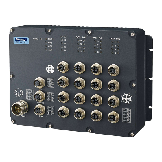
The following view applies to EKI-9516P-HV, EKI-9516P-LV, EKI-9516DP-HV and EKI-9516DP-LV. DATA DATA DATA DATA PWR2 PWR1 EKI-9516P Signal VBUS Pin PWR Signal L 1 /V + L 1 /V - L2/V + L2/V - Pair Console DA - Pair DB -... -
Page 25: Figure 1.3 Front View
The following view applies to EKI-9512 and EKI-9512D. DATA DATA DATA PWR2 PWR1 EKI-9512 Signal VBUS Pin PWR Signal L 1 /V + L 1 /V - L2/V + L2/V - Pair Console DA - Pair DB - P1-N P1-P DD - P2-N P2-P... -
Page 26: Figure 1.4 Front View
The following view applies to EKI-9512P-HV, EKI-9512P-LV, EKI-9512DP-HV and EKI-9512DP-LV. DATA DATA DATA PWR2 PWR1 EKI-9512P Signal VBUS Pin PWR Signal L 1 /V + L 1 /V - L2/V + L2/V - Pair Console DA - Pair DB - P1-N P1-P P2-N... -
Page 27: Figure 1.5 System Led Panel
Link down Green on Providing power over 15.4 W. (only available in Blink green Providing power under 15.4 W. EKI-9516P-LV, User turns off PoE mode at corresponding Giga- EKI-9516P-HV, bit Ethernet port. EKI-9512P-LV, EKI-9512P-HV, EKI-9516DP-LV, EKI-9516DP-HV, EKI-9512DP-LV EKI-9512DP-HV) EKI-9500 Series User Manual... -
Page 28: Chapter 2 Switch Installation
Chapter Switch Installation... -
Page 29: Installation Guidelines
Installation Guidelines The following guidelines are provided to optimize the device performance. Review the guidelines before installing the device. Make sure cabling is away from sources of electrical noise. Radios, power lines, and fluorescent lighting fixtures can interference with the device performance. ... -
Page 30: Figure 2.1 Securing Wall Mounting Screws
Insert the screws into the wall sinks. Leave a 6 mm gap between the wall and the screw head to allow for wall mount plate insertion. 10 mm 4.0 mm 4.0 mm (Max: 4.3mm) Figure 2.1 Securing Wall Mounting Screws ... -
Page 31: Power Supply Installation
Power Supply Installation 2.4.1 Overview Warning! Power down and disconnect the power cord before servicing or wiring the switch. Caution! Do not disconnect modules or cabling unless the power is first switched off. The device only supports the voltage outlined in the type plate. Do not use any other power components except those specifically designated for the switch device. -
Page 32: Grounding The Device
Do not bundle together wiring with similar electrical characteristics. Make sure to separate input and output wiring. Label all wiring and cabling to the various devices for more effective manage- ment and servicing. Note! Routing communications and power wiring through the same conduit may cause signal interference. -
Page 33: Wiring The Power Inputs
Electromagnetic Interference (EMI) affects the transmission performance of a device. By properly grounding the device to earth ground through a drain wire, you can setup the best possible noise immunity and emissions. DATA DATA DATA PWR2 PWR1 EKI-9512P Signal VBUS Pin PWR L 1 /V + Signal... -
Page 34: Connector
Remove the protection cap from the power input. Figure 2.5 Removing the Protection Cap Secure the power cable to the power input. Figure 2.6 Installing the Power Cable The power input is now connected to the switch. The switch can be powered on. 2.4.4.1 Standard M23 6-Pin Male Pin Assignment This section describes the proper connection of the 12, 24, -48, 110, 125 and... -
Page 35: Connecting The Ethernet Media
Description L1/V+ L1/V- L2/V+ L2/V- Connecting the Ethernet Media 2.5.1 Connecting the 10/100/1000BaseT(X) The managed Ethernet models have four Gigabit Ethernet ports (8-pin shielded M12 connector with X coding) or Fast Ethernet ports (4-pin shielded M12 connector with D coding) circular connectors. The 10/100/1000BaseT(X) ports located on the switch's front side are used to connect to Ethernet-enabled devices. -
Page 36: Alarm Contact For Monitoring Internal Power
The console port, used to access the managed switch’s software, has an 8-pin M12 (male) port. A console cable with the mating M12 (female) port and both a DB-9 and / or a USB connector is available for purchase from Advantech. 2.7.0.1 Pin Assignment Figure 2.11 M12 Console Pin Assignment... -
Page 37: Connecting The Usb Terminal
Connecting the USB Terminal 2.8.0.1 Pin Assignment Figure 2.12 M12 Console Pin Assignment Description VBUS EKI-9500 Series User Manual... -
Page 38: Chapter 3 Configuration Utility
Chapter Configuration Utility... -
Page 39: First Time Setup
First Time Setup 3.1.1 Overview The Industrial Ethernet Managed Switch is a configurable device that facilitates the interconnection of Ethernet devices on an Ethernet network. This includes comput- ers, operator interfaces, I/O, controllers, RTUs, PLCs, other switches/hubs or any device that supports the standard IEEE 802.3 protocol. This switch has all the capabilities of a store and forward Ethernet switch plus advanced management features such as SNMP, RSTP and port mirroring. -
Page 40: Using The Graphical (Web) Interface
3.1.4 Using the Graphical (Web) Interface The graphical interface is provided via a web server in the switch and can be accessed via a web browser such as Opera, Mozilla, or Internet Explorer. Note! JavaScript must be supported and enabled in your browser for the graphical interface to work correctly. -
Page 41: Configuring The Ethernet Ports
3.1.6 Configuring the Ethernet Ports The switch comes with default port settings that should allow you to connect to the Ethernet Ports with out any necessary configuration. Should there be a need to change the name of the ports, negotiation settings or flow control settings, you can do this in the Port Configuration menu. -
Page 42: Accessing The Cli
– parameter will specify the parameter within the section. For example, the net- work section will have parameters for DHCP, IP address, subnet mask, and default gateway. – value is the new value of the parameter. If value is omitted, the current value is displayed. -
Page 43: Managing Switch
Chapter Managing Switch... -
Page 44: Log In
Log In To access the login window, connect the device to the network, see “Connecting the Ethernet Media” on page 16. Once the switch is installed and connected, power on the switch see the following procedures to log into your switch. When the switch is first installed, the default network configuration is set to DHCP enabled. -
Page 45: System
In the Password field, type in the new password. Re-type the same password in the Confirm field. Click Submit to change the current account settings. Figure 4.3 Changing a Default Password After saving all the desired settings, perform a system save (Save Configuration). The changes are saved. - Page 46 Item Description Access Type The way the user accesses the system. This field can be configured only when adding a new authentication list, and only the Login and Enable access types can be selected. The access types are as fol- lows: ...
-
Page 47: Figure 4.5 System > Aaa > Authentication List > Add
To add a new authentication list: Click System > AAA > Authentication List > Add. Figure 4.5 System > AAA > Authentication List > Add The following table describes the items in the previous figure. Item Description Authentication Methods Available Methods The authentication methods that can be used for the authentication list. -
Page 48: Figure 4.7 System > Aaa > Accounting List
The following table describes the items in the previous figure. Item Description Terminal Console The Login authentication list and the Enable authentication list to apply to users who attempt to access the CLI by using a connection to the console port. Telnet The Login authentication list and the Enable authentication list to apply to users who attempt to access the CLI by using a Telnet ses-... -
Page 49: Figure 4.8 System > Aaa > Accounting List > Add
Item Description Method Options The method(s) used to record user activity. The possible methods are as follows: TACACS+: Accounting notifications are sent to the configured TACACS+ server. Radius: Accounting notifications are sent to the configured RADIUS server. List Type The type of accounting list, which is one of the following: ... -
Page 50: Figure 4.9 System > Aaa > Accounting Selection
4.3.1.4 Accounting Selection Use the Accounting List Selection page to associate an accounting list with each access method. For each access method, the following two accounting lists are asso- ciated: Exec: The accounting list to record user login and logout times. ... -
Page 51: Advanced Configuration
4.3.2 Advanced Configuration 4.3.2.1 DHCP Server Global Use the DHCP Server Global Configuration page to configure DHCP global parame- ters. To access this page, click System > Advanced Configuration > DHCP Server > Global. Figure 4.10 System > Advanced Configuration > DHCP Server > Global The following table describes the items in the previous figure. -
Page 52: Server > Excluded Addresses > Add
The following table describes the items in the previous figure. Item Description From The IP address to exclude. In a range of addresses, this value is the lowest address to exclude. The highest address to exclude in a range of addresses. If the excluded address is not part of a range, this field shows the same value as the From field. -
Page 53: Server > Pool Summary > Add
The following table describes the items in the previous figure. Item Description Name The name that identifies the DHCP server pool. Type The type of binding for the pool. The options are: Manual: The DHCP server assigns a specific IP address to the client based on the client's MAC address. - Page 54 Item Description Network Base The network portion of the IP address. A DHCP client can be offered Address any available IP address within the defined network as long as it has not been configured as an excluded address (for dynamic pools only). Network Mask The subnet mask associated with the Network Base Address that sep- arates the network bits from the host bits (for dynamic pools only).
- Page 55 To access this page, click System > Advanced Configuration > DHCP Server > Pool Configuration. Figure 4.15 System > Advanced Configuration > DHCP Server > Pool Configuration The following table describes the items in the previous figure. Item Description Pool Name Select the pool to configure.
- Page 56 Item Description Lease Expiration Indicates whether the information the server provides to the client should expire. Enable: Allows the lease to expire. If you select this option, you can specify the amount of time the lease is valid in the Lease Duration field.
-
Page 57: Server > Pool Options
To access this page, click System > Advanced Configuration > DHCP Server > Pool Options. Figure 4.16 System > Advanced Configuration > DHCP Server > Pool Options The following table describes the items in the previous figure. Item Description Pool Name Select the pool to configure. -
Page 58: Server > Pool Options > Add Vendor Option
To add a new vendor option: Click System > Advanced Configuration > DHCP Server > Pool Options > Add Vendor Option. Figure 4.17 System > Advanced Configuration > DHCP Server > Pool Options > Add Vendor Option The following table describes the items in the previous figure. Item Description Option Code... -
Page 59: Server > Bindings
Item Description Submit Click Submit to save the values. Cancel Click Cancel to close the window. Bindings Use the DHCP Server Bindings page to view information about the IP address bind- ings in the DHCP server database. To access this page, click System > Advanced Configuration > DHCP Server > Bindings. - Page 60 The following table describes the items in the previous figure. Item Description Automatic Bindings The total number of IP addresses from all address pools with auto- matic bindings that the DHCP server has assigned to DHCP clients. Expired Bindings The number of IP addresses that the DHCP server has assigned to DHCP clients that have exceeded the configured lease time.
-
Page 61: Server > Conflicts
To access this page, click System > Advanced Configuration > DHCP Server > Conflicts. Figure 4.21 System > Advanced Configuration > DHCP Server > Conflicts The following table describes the items in the previous figure. Item Description IP Address The IP address that has been detected as a duplicate. Detection Method The method used to detect the conflict, which is one of the following: ... -
Page 62: Ip Mapping
The following table describes the items in the previous figure. Item Description Admin Mode The administrative mode of the DNS client. Default Domain The default domain name for the DNS client to use to complete Name unqualified host names. Domain names are typically composed of a series of labels concatenated with dots. -
Page 63: Ip Mapping > Add
Item Description IP Address The IPv4 or IPv6 address associated with the configured Host Name. For Static entries, specify the IP Address after you click Add. You can specify either an IPv4 or an IPv6 address. Total Time The number of seconds that the entry will remain in the table. The function is only available for Dynamic entries. -
Page 64: Source Interface Configuration
To access this page, click System > Advanced Configuration > DNS > Source Interface Configuration. Figure 4.25 System > Advanced Configuration > DNS > Source Interface Configuration The following table describes the items in the previous figure. Item Description Type The type of interface to use as the source interface: ... -
Page 65: Alerts > Test
Item Description Log Duration Determines how frequently the non critical messages are sent to the (Minutes) SMTP server. Submit Click Submit to save the values and update the screen. Refresh Click Refresh to update the screen. Cancel Click Cancel to restore default value. Test Use the Email Alert Test page to verify that the Email alert settings are configured properly. -
Page 66: Alerts > Server > Add
Item Description Password If the Security is TLSv1, this field specifies the password associated with the configured user name for mail server access. When adding or editing the server, you must retype the password to confirm that it is entered correctly. Refresh Click Refresh to update the screen. -
Page 67: Alerts > Subject
Item Description Number of Emails The number of email alerts that failed to be sent since the counters Failed were cleared or system was reset. Time Since Last The amount of time in days, hours, minutes, and seconds that has Email Sent passed since the last email alert was successfully sent. -
Page 68: Alerts > Address > Add
To add a new Email alert to address: Click System > Advanced Configuration > Email Alerts > Address > Add. Figure 4.33 System > Advanced Configuration > Email Alerts > Address > Add The following table describes the items in the previous figure. Item Description To Address... -
Page 69: Cache Table
Item Description Hold Time Interval The number of seconds the neighbor device should consider the infor- (Seconds) mation it receives in an ISDP packet to be valid. Device ID The identification information the device advertises to its neighbors in the ISDP packets. Device ID Format The possible formats that the device can use for identification pur- Capability... -
Page 70: Interface
Interface Use the ISDP Interface Configuration page to configure the ISDP settings for each interface. To access this page, click System > Advanced Configuration > ISDP > Interface. Figure 4.36 System > Advanced Configuration > ISDP > Interface The following table describes the items in the previous figure. Item Description Interface... -
Page 71: Dependency > Group
Item Description ISDPv1 Packets The total number of ISDP version 1 packets transmitted by the device. Transmitted ISDPv2 Packets The total number of ISDP version 2 packets received by the device. Received ISDPv2 Packets The total number of ISDP version 2 packets transmitted by the device. Transmitted Bad Header The total number of ISDP packets received with bad headers. -
Page 72: Dependency > Group > Add
Item Description Link Action The action performed on downstream interfaces when the upstream interfaces are down, which can be one of the following: Up: Downstream interfaces are up when upstream interfaces are down. Down: Downstream interfaces go down when upstream inter- faces are down. -
Page 73: Denial Of Service
Item Description Submit Click Submit to save the values. Cancel Click Cancel to close the window. 4.3.2.6 Protection Denial of Service Use the Denial of Service (DoS) Configuration page to configure DoS control. FAST- PATH SMB software provides support for classifying and blocking specific types of DoS attacks. -
Page 74: Agent
Item Description TCP Fragment Enable this option to allow the device to drop packets that have a TCP payload where the IP payload length minus the IP header size is less than the minimum allowed TCP header size. TCP Offset Enable this option to allow the device to drop packets that have a TCP header Offset set to 1. -
Page 75: Poller
agent on the device. The sFlow agent can send packet sampling data to multiple sFlow receivers on the network. To access this page, click System > Advanced Configuration > sFlow > Receiver. Figure 4.42 System > Advanced Configuration > sFlow > Receiver The following table describes the items in the previous figure. -
Page 76: Poller > Add
Item Description Receiver Index The sFlowReceiver for this sFlow counter poller. The specified Receiver Index must be associated with an active sFlow receiver. If a receiver expires, all pollers associated with the receiver will also expire. Poller Interval The maximum number of seconds between successive samples of the counters associated with this data source. -
Page 77: Sampler
To access this page, click System > Advanced Configuration > sFlow > Sampler. Figure 4.45 System > Advanced Configuration > sFlow > Sampler The following table describes the items in the previous figure. Item Description Sampler Data Source The sFlowDataSource for this sFlow sampler. The sFlow agent sup- ports physical ports as sFlow data sources. -
Page 78: Source Interface Configuration
Source Interface Configuration Use the sFlow Source Interface Configuration page to specify the physical or logical interface to use as the sFlow client source interface. When an IP address is config- ured on the source interface, this address is used for all sFlow communications between the local sFlow client and the remote sFlow server. -
Page 79: Community > Add Community
The following table describes the items in the previous figure. Item Description Community Name Community name used in SNMPv1/v2 packets. This is configured in the client and identifies the access the user may connect with. Security Name Identifies the security entry that associates communities and Groups for a specific access type. -
Page 80: Community > Add Community Group
To add a new SNMP community group: Click System > Advanced Configuration > SNMP > Community > Add Commu- nity Group. Figure 4.50 System > Advanced Configuration > SNMP > Community > Add Community Group The following table describes the items in the previous figure. Item Description Community Name... -
Page 81: Trap Receiver V1/V2 > Add
Item Description Timeout Value The number of seconds to wait for an acknowledgment from the SNMP management host before resending an inform message. Retries The number of times to resend an inform message that is not acknowledged by the SNMP management host. Filter The name of the filter for the SNMP management host. -
Page 82: Trap Receiver V3
Item Description Filter The name of the filter for the SNMP management host. The filter is configured by using the CLI and defines which MIB objects to include or exclude from the view. This field is optional. UDP Port The UDP port on the SNMP management host that will receive the SNMP notifications. -
Page 83: Trap Receiver V3 > Add
Item Description UDP Port The UDP port on the SNMP management host that will receive the SNMP notifications. If no value is specified when configuring a receiver, the default UDP port value is used. Refresh Click Refresh to update the screen. Click Add to add a new SNMP trap receiver. -
Page 84: Supported Mibs
Item Description Timeout Value (Sec- The number of seconds to wait for an acknowledgment from the onds) SNMP receiver before resending an inform message. Filter The name of the filter for the SNMP management host. The filter is configured by using the CLI and defines which MIB objects to include or exclude from the view. -
Page 85: Access Control Group
To access this page, click System > Advanced Configuration > SNMP > Access Control Group. Figure 4.56 System > Advanced Configuration > SNMP > Access Control Group The following table describes the items in the previous figure. Item Description Group Name The name that identifies the SNMP group. -
Page 86: Access Control Group > Add
To add a new access control group: Click System > Advanced Configuration > SNMP > Access Control Group > Add. Figure 4.57 System > Advanced Configuration > SNMP > Access Control Group > Add The following table describes the items in the previous figure. Item Description Access Control Group... -
Page 87: User Security Model
Item Description Write The level of write access rights for the group. The menu includes the available SNMP views. When adding a group, select the check box to allow the field to be configured, then select the desired view that per- mits management read-write access to the contents of the agent but not to the community. -
Page 88: User Security Model > Add
Item Description Refresh Click Refresh to update the screen. Click Add to add a new SNMP user. Remove Click Remove to remove the selected entries. To add a new SNMP user: Click System > Advanced Configuration > SNMP > User Security Model > Add. Figure 4.59 System >... -
Page 89: Source Interface Configuration
Item Description Privacy Specifies the privacy protocol to be used on encrypted messages on behalf of the specified user. This parameter is only valid if the Authen- tication method parameter is not NONE. DES: DES protocol will be used. ... -
Page 90: Global Configuration
To access this page, click System > Advanced Configuration > SNMP > Server Configuration. Figure 4.61 System > Advanced Configuration > SNMP > Server Configuration The following table describes the items in the previous figure. Item Description SNMP Server Port The UDP port number on which the SNMP server listens for requests. -
Page 91: Global Status
Item Description Unicast Poll Timeout Specifies the timeout value, in seconds, to wait for an SNTP response (Seconds) when configured in unicast mode. Unicast Poll Retry Specifies the number of times to retry a request to an SNTP server after the first time-out before attempting to use the next configured server when configured in unicast mode. -
Page 92: Server Configuration
Item Description Last Attempt Status Specifies the status of the last SNTP request or unsolicited message for both unicast and broadcast modes. If no message has been received from a server, a status of Other is displayed. These values are appropriate for all operational modes. ... -
Page 93: Server Configuration > Add
The following table describes the items in the previous figure. Item Description SNTP Server The address or host name of an SNTP server the device can use to synchronize the system time. Type The configured SNTP server address type, which can be IPv4, IPv6, or DNS. -
Page 94: Figure 4.66 System > Advanced Configuration > Sntp Server Status
The SNTP Server Status page displays status information about the SNTP servers configured on your switch. To access this page, click System > Advanced Configuration > SNTP > Server Status. Figure 4.66 System > Advanced Configuration > SNTP > Server Status The following table describes the items in the previous figure. -
Page 95: Source Interface Configuration
To access this page, click System > Advanced Configuration > SNTP > Source Interface Configuration. Figure 4.67 System > Advanced Configuration > SNTP > Source Interface Configuration The following table describes the items in the previous figure. Item Description Type The type of interface to use as the source interface: ... -
Page 96: Ranges > Configuration > Add
The following table describes the items in the previous figure. Item Description Admin Mode Enables or disables the Time Range administrative mode. When enabled, actions with subscribed components are performed for exist- ing time range entries. Time Range Name The unique ID or name that identifies this time range. A time-based ACL rule can reference the name configured in this field. -
Page 97: Ranges > Entry Configuration
To access this page, click System > Advanced Configuration > Time Ranges > Entry Configuration. Figure 4.70 System > Advanced Configuration > Time Ranges > Entry Configuration The following table describes the items in the previous figure. Item Description Time Range Name Click the drop-down menu to select a time range. -
Page 98: Ranges > Entry Configuration > Add Periodic
The following table describes the items in the previous figure. Item Description Time Range Name The time range configuration that will include the Absolute time range entry. Start Time Select this option to configure values for the Start Date and the Start- ing Time of Day. -
Page 99: Zone > Summary
The following table describes the items in the previous figure. Item Description Time Range Name The time range configuration that will include the Periodic time range entry. Applicable Days Select the days on which the Periodic time range entry is active: ... - Page 100 The following table describes the items in the previous figure. Item Description Current Time Time The current time on the system clock. This time is used to provide time stamps on log messages. Additionally, some CLI show com- mands include the time in the command output. Zone The acronym that represents the time zone.
-
Page 101: Zone > Time Zone
To access this page, click System > Advanced Configuration > Time Zone > Time Zone. Figure 4.74 System > Advanced Configuration > Time Zone > Time Zone The following table describes the items in the previous figure. Item Description Time Zone Offset The system clock's offset from UTC, which is also known as Green- wich Mean Time (GMT). - Page 102 The following table describes the items in the previous figure. Item Description Summer Time The summer time mode on the system: Disable: Summer time is not active, and the time does not shift based on the time of year. ...
-
Page 103: Manager > Alarm Status
4.3.2.12 Event Manager The pages in the Event Manager folder allow you to view and configure information about alarm LED, alarm relay, alarm relay2, logs, Email and SNMP traps the system generates. Alarm Status Use the Alarm Status page to view the current alarm status for alarm LED, alarm relay and alarm relay2. -
Page 104: Manager > Policy List
The following table describes the items in the previous figure. Item Description Trap Log Capacity The maximum number of traps the log can store. If the number of traps exceeds the capacity, new entries overwrite the oldest entries. Number of Traps The number of traps the system has generated since the trap log Since Last Reset entries were last cleared, either by clicking Clear Log or by resetting... -
Page 105: Manager > Policy List > Add
To add a new policy list: Click System > Advanced Configuration > Event Manager > Policy List > Add. Figure 4.79 System > Advanced Configuration > Event Manager > Policy List > The following table describes the items in the previous figure. Item Description List Name... -
Page 106: Manager > Severity Configuration
The following table describes the items in the previous figure. Item Description Alarm LED The policy list to trigger system alarm LED as always on, blinking or off. Alarm Relay The policy list to trigger system alarm relay as always on or off. Alarm Relay 2 The policy list to trigger system alarm relay 2 as always on or off. -
Page 107: Basic Configuration
4.3.3 Basic Configuration 4.3.3.1 Switch IEEE 802.3x flow control works by pausing a port when the port becomes oversub- scribed and dropping all traffic for small bursts of time during the congestion condi- tion. This can lead to high-priority and/or network control traffic loss. When 802.3x flow control is enabled, lower speed switches can communicate with higher speed switches by requesting that the higher speed switch refrains from sending packets. -
Page 108: Figure 4.84 System > Configuration Storage > Reset
The following table describes the items in the previous figure. Item Description Save Click Save to initiate a save of all system configuration after display- ing a confirmation message. All of the current system configuration settings, including any that have been changed by the user, are stored into non-volatile memory so that they are preserved across a system reset. -
Page 109: Connectivity
To access this page, click System > Configuration Storage > Copy. Figure 4.86 System > Configuration Storage > Copy The following table describes the items in the previous figure. Item Description Source File Select the configuration file that will overwrite the contents in the selected destination file. - Page 110 The following table describes the items in the previous figure. Item Description Network Configura- Specify how the device acquires network information on the network tion Protocol interface: None: The device does not attempt to acquire network informa- tion dynamically. Select this option to configure a static IP address, subnet mask, and default gateway.
-
Page 111: Figure 4.88 System > Connectivity > Ipv6
4.3.5.2 IPv6 Use the IPv6 Network Connectivity page to configure and view IPv6 information on the network interface. The network interface is the logical interface that allows remote management of the device via any of the front-panel switch ports. To enable manage- ment of the device over an IPv6 network by using a Web browser, SNMP, Telnet, or SSH, you must first configure the device with the appropriate IPv6 information. -
Page 112: Figure 4.89 System > Connectivity > Ipv6 Neighbors
Item Description Dynamic IPv6 Lists the IPv6 addresses on the network interface that have been Addresses dynamically configured through IPv6 auto configuration or DHCPv6. Default IPv6 Routers Lists the IPv6 address of each default router that has been automati- cally configured through IPv6 router discovery. Submit Click Submit to save the values and update the screen. -
Page 113: Figure 4.90 System > Connectivity > Ipv6 Neighbors > Add
Item Description Click Add to add a new network port IPv6 neighbor. Remove Click Remove to remove the selected entries. To add a new network port IPv6 neighbor: Click System > Connectivity > IPv6 Neighbors > Add. Figure 4.90 System > Connectivity > IPv6 Neighbors > Add The following table describes the items in the previous figure. -
Page 114: Figure 4.92 System > Connectivity > Service Port Ipv6
Item Description DHCP Client Identi- The DHCP Client Identifier (Option 61) is used by DHCP clients to fier specify their unique identifier. DHCP servers use this value to index their database of address bindings. This value is expected to be unique for all clients in an administrative domain. -
Page 115: Figure 4.93 System > Connectivity > Service Port Ipv6 Neighbors
Item Description IPv6 Stateless Sets the IPv6 stateless address auto configuration mode on the ser- Address AutoConfig vice port. Mode Enabled: The service port can acquire an IPv6 address through IPv6 Neighbor Discovery Protocol (NDP) and through the use of Router Advertisement messages. -
Page 116: Figure 4.94 System > Connectivity > Service Port Ipv6 Neighbors List > Add
The following table describes the items in the previous figure. Item Description IPv6 Addresses The IPv6 address of a neighbor device that has been reachable on the local link through the service port. MAC Address The MAC address of the neighboring device. Type The type of the neighbor entry, which is one of the following: ... -
Page 117: Figure 4.95 System > Connectivity > Dhcp Client Options
4.3.5.7 DHCP Client Options Use the DHCP Client Options page to configure DHCP client settings on the system. To access this page, click System > Connectivity > DHCP Client Options. Figure 4.95 System > Connectivity > DHCP Client Options The following table describes the items in the previous figure. Item Description DHCP Vendor Class... -
Page 118: Figure 4.97 System > Firmware > Configuration And Upgrade
and add a description to each image on the device. The device uses the HTTP proto- col to transfer the image, and the image is saved as the backup image. To access this page, click System > Firmware > Configuration and Upgrade. Figure 4.97 System >... -
Page 119: Figure 4.98 System > Logs > Buffered Log
reaches the configured maximum size, the oldest message is deleted from the RAM when a new message is added. If the system restarts, all messages are cleared. To access this page, click System > Logs > Buffered Log. Figure 4.98 System > Logs > Buffered Log The following table describes the items in the previous figure. -
Page 120: Figure 4.99 System > Logs > Event Log
To access this page, click System > Logs > Event Log. Figure 4.99 System > Logs > Event Log The following table describes the items in the previous figure. Item Description Log Index A display row index number used to identify the event log entry, with the most recent entry listed first (lowest number). -
Page 121: Figure 4.101System > Logs > Hosts
Item Description Severity The severity level associated with the log entry. The severity can be one of the following: Emergency (0): The device is unusable. Alert (1): Action must be taken immediately. Critical (2): The device is experiencing primary system failures. ... -
Page 122: Figure 4.102System > Logs > Hosts > Add
Click System > Logs > Hosts > Add. Figure 4.102 System > Logs > Hosts > Add The following table describes the items in the previous figure. Item Description IP Address/Host The IP address or DNS-resolvable host name of the remote host to Name receive log messages. -
Page 123: Figure 4.104System > Logs > Source Interface Configuration
Item Description Console Log Configuration Admin Mode Enable or disable logging to any serial device attached to the host. Severity Filter Select the severity of the messages to be logged. All messages at and above the selected threshold are logged to the console. The severity can be one of the following: ... -
Page 124: Figure 4.105System > Logs > Statistics
The following table describes the items in the previous figure. Item Description Type The type of interface to use as the source interface: None: The primary IP address of the originating (outbound) interface is used as the source address. ... -
Page 125: Management Access
4.3.8 Management Access 4.3.8.1 System Use the System Connectivity page to control access to the management interface by administratively enabling or disabling various access methods. To access this page, click System > Management Access > System. Figure 4.106 System > Management Access > System The following table describes the items in the previous figure. -
Page 126: Figure 4.107System > Management Access > Telnet
The Telnet Session Configuration page allows you to control inbound telnet settings on the switch. Inbound telnet sessions originate on a remote system and allow a user on that system to connect to the switch CLI. To access this page, click System > Management Access > Telnet. Figure 4.107 System >... -
Page 127: Figure 4.109System > Management Access > Cli Banner
The following table describes the items in the previous figure. Item Description Serial Time Out (Min- Serial port inactivity timeout value, in minutes. A logged-in user who utes) does not exhibit any CLI activity through the serial port connection for this amount of time is automatically logged out of the device. -
Page 128: Figure 4.110System > Management Access > Http
To access this page, click System > Management Access > HTTP. Figure 4.110 System > Management Access > HTTP The following table describes the items in the previous figure. Item Description HTTP Admin Mode Enables or disables the HTTP administrative mode. When enabled, the device can be accessed through a web browser using the HTTP protocol. - Page 129 The following table describes the items in the previous figure. Item Description HTTPS Admin Mode Enables or disables the HTTPS administrative mode. When this mode is enabled, the device can be accessed through a web browser using the HTTPS protocol. TLS Version 1 Enables or disables Transport Layer Security Version 1.0.
-
Page 130: Figure 4.112System > Management Access > Ssh
To access this page, click System > Management Access > SSH. Figure 4.112 System > Management Access > SSH The following table describes the items in the previous figure. Item Description SSH Admin Mode Enables or disables the SSH server administrative mode. When this mode is enabled, the device can be accessed by using an SSH client on a remote system. -
Page 131: Passwords
Item Description Refresh Click Refresh to update the screen. Cancel Click Cancel to restore default value. 4.3.9 Passwords 4.3.9.1 Line Password Use the Line Password Configuration page to configure line mode passwords. To access this page, click System > Passwords > Line Password. Figure 4.113 System >... -
Page 132: Figure 4.115System > Passwords > Password Rules
Item Description Refresh Click Refresh to update the screen. Cancel Click Cancel to restore default value. 4.3.9.3 Password Rules Use the Password Rules page to configure settings that apply to all user passwords. To access this page, click System > Passwords > Password Rules. Figure 4.115 System >... -
Page 133: Figure 4.116System > Passwords > Last Password
Item Description Minimum Character This minimum number of character classes, defined as the various Classes password strength categories listed above, that must be met in order for a password to be considered valid. It is permissible, therefore, to define strength checking criteria for each of the different types of con- ditions, but only require a valid password to meet some of them. -
Page 134: Figure 4.117System > Passwords > Reset Passwords
To access this page, click System > Passwords > Reset Passwords. Figure 4.117 System > Passwords > Reset Passwords The following table describes the items in the previous figure. Item Description Reset Click Reset to initiates a reset of all login passwords to their factory default setting after displaying a confirmation message. -
Page 135: Figure 4.119System > Poe > Poe Port Configuration And Status
Item Description Power Supply Volt- The measured usage voltage of PSE in dV. age (dV) Temperature Guard Configure PoE temperature guard threshold. Threshold (°C) System Tempera- The measured temperature of PSE in degree Celsius. ture (°C) System Fault Indica- The fault status of the PSE. tion Submit Click Submit to save the values and update the screen. -
Page 136: Figure 4.120System > Poe > Poe Port Statistics
Item Description Current Consump- The interface port output current(milliAmp) drawn by device. tion Detection Status The status of the port as a provider of PoE. Such devices are referred to as PSE. The status can be one of the following: ... -
Page 137: Figure 4.121System > Port > Summary
Item Description Refresh Click Refresh to update the screen. Clear Counters Click Clear Counters to reset all counters to zero. 4.3.11 Port The pages in the Port folder allow you to view and monitor the physical port informa- tion for the ports available on the switch. The Port folder has links to the following pages: 4.3.11.1 Summary... -
Page 138: Figure 4.122System > Port > Description
Item Description STP Mode The Spanning Tree Protocol (STP) Administrative Mode associated with the port or LAG. STP is a layer 2 protocol that provides a tree topology for switches on a bridged LAN. STP allows a network to have redundant paths without the risk of network loops. -
Page 139: Figure 4.123System > Port > Cable Test
Item Description Refresh Click Refresh to update the screen. Edit Click Edit to edit the selected entries. 4.3.11.3 Cable Test The cable test feature enables you to determine the cable connection status on a selected port. You can also obtain an estimate of the length of the cable connected to the port, if the PHY on the ports supports this functionality. -
Page 140: Figure 4.124System > Port > Mirroring
4.3.11.4 Mirroring Port mirroring selects the network traffic for analysis by a network analyzer. This is done for specific ports of the switch. As such, many switch ports are configured as source ports and one switch port is configured as a destination port. You have the ability to configure how traffic is mirrored on a source port. -
Page 141: Figure 4.125System > Port > Transceiver Brief
Item Description Source The ports or VLAN configured to mirror traffic to the destination. You can configure multiple source ports or one source VLAN per session. The source VLAN can also be a remote VLAN. Direction The direction of traffic on the source port (or source ports) or VLAN that is sent to the specified destination. -
Page 142: Figure 4.126System > Statistics > System > Switch
4.3.12 Statistics 4.3.12.1 System Switch The Switch Statistics page shows summary information about traffic transmitted and received on the device, entries in the MAC address table, and Virtual Local Area Net- works (VLANs) that exist on the device. To access this page, click System > Statistics > System > Switch. Figure 4.126 System >... -
Page 143: Figure 4.127System > Statistics > System > Port Summary
Item Description Static Entries The current number of entries in the MAC address table or VLAN database that an administrator has statically configured. Dynamic Entries The current number of entries in the MAC address table or VLAN database that have been dynamically learned by the device. Total Entries Deleted The number of VLANs that have been created and then deleted since the last reboot. -
Page 144: Figure 4.128System > Statistics > System > Port Detailed
Item Description Clear Counters Click Clear Counters to reset the selected counters to zero. Clear All Counters Click Clear All Counters to reset all counters to zero. Port Detailed The Port Detailed Statistics page shows detailed information about the traffic trans- mitted and received by each interface. -
Page 145: Figure 4.129System > Statistics > System > Network Dhc Pv6
Item Description FCS Errors Frame Check Sequence errors may occur if a network link is bad or if packets are being dropped. Protocol The table shows statistics about various protocol data units (PDUs) or EAPOL frames transmitted or received by the interface. Statistics for transmitted traffic and received traffic are shown in separate columns. -
Page 146: Figure 4.130System > Statistics > Time Based > Group
Item Description Request Packets Number of DHCPv6 request messages the client sent in response to Transmitted a DHCPv6 server's advertisement message. Renew Packets Number of renew messages the DHCPv6 client has sent to the server Transmitted to request an extension of the lifetime of the information provided by the server. -
Page 147: Figure 4.131System > Statistics > Time Based > Group Add
Item Description Time Range The name of the periodic or absolute time range to use for data collec- tion. The time range is configured by using the Time Range Summary and Time Range Entry Summary pages. The time range must be con- figured on the system before the time-based statistics can be col- lected. - Page 148 The following table describes the items in the previous figure. Item Description Group The type of traffic statistics to collect for the group, which is one of the following: Received: The number of packets received on the interfaces within the group. ...
-
Page 149: Figure 4.132System > Statistics > Time Based > Flow Based
To access this page, click System > Statistics > Time Based > Flow Based. Figure 4.132 System > Statistics > Time Based > Flow Based The following table describes the items in the previous figure. Item Description Reporting Methods The methods for reporting the collected statistics at the end of every configured interval. -
Page 150: Figure 4.133System > Statistics > Time Based > Flow Based > Add
Click System > Statistics > Time Based > Flow Based > Add. Figure 4.133 System > Statistics > Time Based > Flow Based > Add The following table describes the items in the previous figure. Item Description Rule Id The number that identifies the flow-based statistics collection rule. Time Range The name of the periodic or absolute time range to use for data collec- tion. -
Page 151: Figure 4.134System > Statistics > Time Based > Statistics
Statistics Use the Time Based Statistics page to view time-based statistics collected for the configured traffic groups and flow-based rules. To access this page, click System > Statistics > Time Based > Statistics. Figure 4.134 System > Statistics > Time Based > Statistics The following table describes the items in the previous figure. -
Page 152: Figure 4.136System > Status > Resource Status
The following table describes the items in the previous figure. Item Description MAC Address The physical (MAC) address associated with the IP address of the connection. IP Address The Internet (IP) address of the connection. Interface Shows the switch port through which the connection was established, or displays as Management if the connection occurred via a non-net- work port interface (if applicable). -
Page 153: Figure 4.137System > Status > Resource Configuration
Item Description 60 Seconds The percentage amount of CPU utilization consumed by the corre- sponding task in the last 60 seconds. 300 Seconds The percentage amount of CPU utilization consumed by the corre- sponding task in the last 300 seconds. Refresh Click Refresh to update the screen. - Page 154 The following table describes the items in the previous figure. Item Description System Information System Description The product name of this device. System Name The configured name used to identify this device. System Location The configured location of this device. System Contact The configured contact person for this device.
-
Page 155: Figure 4.139System > Summary > Description
To access this page, click System > Summary > Description. Figure 4.139 System > Summary > Description The following table describes the items in the previous figure. Item Description System Description The product name of this device. System Name The name used to identify this device. The factory default is blank. System Location The location of this device. -
Page 156: Figure 4.141System > Summary > Mac Address Table
The following table describes the items in the previous figure. Item Description System Description The product name of this device. Machine Type The hardware platform of this device. Machine Model The product model number. Serial Number The unique serial number used to identify the device. Manufacturer The two-octet code that identifies the manufacturer. -
Page 157: Users
Item Description Status Provides information about the entry and why it is in the table, which can be one of the following: Static: The address has been manually configured and does not age out. Learned: The address has been automatically learned by the device and can age out when it is not in use. -
Page 158: Figure 4.143System > Users > Accounts > Add
Item Description Access Level The access or privilege level for this user. The options are: Privilege-15: The user can view and modify the configuration. Privilege-1: The user can view the configuration but cannot mod- ify any fields. Privilege-0: The user exists but is not permitted to log on to the device. -
Page 159: Figure 4.144System > Users > Auth Server Users
Item Description Password Strength Shows the status of password strength check. Encrypted Password Specifies the password encryption. Submit Click Submit to save the values. Cancel Click Cancel to close the window. 4.3.15.2 Auth Server Users Use the Auth Server Users page to add and remove users from the local authentica- tion server user database. -
Page 160: Utilities
Item Description Password Required Select this option to indicate that the user must enter a password to be authenticated. If this option is clear, the user is required only to enter a valid user name. Password Specify the password to associate with the user name (if required). Confirm Re-enter the password to confirm the entry. -
Page 161: Figure 4.148System > Utilities > Ping
The following table describes the items in the previous figure. Item Description Reset Click Reset to initiates the system reset action after displaying a con- firmation message. 4.3.16.2 Ping Use the Ping page to tell the switch to send a Ping request to a specified IP address. You can use this feature to check whether the switch can communicate with a partic- ular network host. -
Page 162: Figure 4.149System > Utilities > Ping Ipv6
Item Description Start Click Start to start the ping test. The device sends the specified num- ber of ping packets to the host. Stop Click Stop to interrupts the current ping test. 4.3.16.3 Ping IPv6 Use the Ping IPv6 page to tell the device to send one or more ping requests to a specified IPv6 host. -
Page 163: Figure 4.150System > Utilities > Traceroute
4.3.16.4 TraceRoute Use the TraceRoute page to determine the layer 3 path a packet takes from the device to a specific IP address or hostname. When you initiate the TraceRoute com- mand by clicking the Start button, the device sends a series of TraceRoute probes toward the destination. - Page 164 Item Description Status The current status of the TraceRoute, which can be: Not Started: The TraceRoute has not been initiated since view- ing the page. In Progress: The TraceRoute has been initiated and is running. Stopped: The TraceRoute was interrupted by clicking the Stop button.
-
Page 165: Figure 4.151System > Utilities > Traceroute Ipv6
To access this page, click System > Utilities > TraceRoute IPv6. Figure 4.151 System > Utilities > TraceRoute IPv6 The following table describes the items in the previous figure. Item Description Host Name or IPv6 The DNS-resolvable hostname or IPv6 address of the system to Address attempt to reach. -
Page 166: Figure 4.152System > Utilities > Ip Address Conflict
Item Description Results The results of the TraceRoute, which are displayed in the following format: 1 3001::1 708 ms 41 ms 11 ms 2 4001::2 250 ms 200 ms 193 ms 3 5001::3 289 ms 313 ms 278 ms 4 6001::4 651 ms 41 ms 270 ms 5 :: * N * N * N Hop Count = 4 Last TTL = 5 Test attempt = 1 Test Success = 0 For each TTL value probed, the results show the IP address of the... -
Page 167: Figure 4.153System > Utilities > Transfer
The following table describes the items in the previous figure. Item Description Status IP Address Conflict Indicates whether a conflicting IP address has been detected since Currently Exists this status was last reset. False: No conflict detected (the subsequent fields on this page display as N/A). - Page 168 Item Description File Type: Specify the type of file to transfer from the device to a remote system. – Active Code: Select this option to transfer an active image. – Backup Code: Select this option to transfer an backup image. –...
- Page 169 Item Description File Type: Specify the type of file to transfer to the device: – Active Code: Select this option to transfer a new image to the device. The code file is stored as the active image. – Backup Code: Select this option to transfer a new image to the device.
-
Page 170: Switching
Item Description Select File: If HTTP is the Transfer Protocol, browse to the direc- tory where the file is located and select the file to transfer to the device. This field is not present if the Transfer Protocol is TFTP or FTP. -
Page 171: Dhcp Snooping
To access this page, click Switching > Class of Service > 802.1p. Figure 4.154 Switching > Class of Service > 802.1p The following table describes the items in the previous figure. Item Description Interface The interface associated with the rest of the data in the row. The Global entry represents the common settings for all interfaces, unless specifically overridden individually. -
Page 172: Figure 4.156Switching > Dhcp Snooping > Base > Vlan Configuration
VLAN Configuration Use the DHCP Snooping VLAN Configuration page to view and configure the DHCP snooping settings on VLANs that exist on the device. DHCP snooping can be config- ured on switching VLANs and routing VLANs. For Layer 2 (non-routing) VLANs, DHCP snooping forwards valid DHCP client messages received on the VLANs. -
Page 173: Figure 4.158Switching > Dhcp Snooping > Base > Interface Configuration
Interface Configuration Use the DHCP Snooping Interface Configuration page to view and configure the DHCP snooping settings for each interface. The DHCP snooping feature processes incoming DHCP messages. For DHCPRELEASE and DHCPDECLINE messages, the feature compares the receive interface and VLAN with the client's interface and VLAN in the binding database. -
Page 174: Figure 4.159Switching > Dhcp Snooping > Base > Static Bindings
Item Description Rate Limit (pps) The rate limit value for DHCP packets received on the interface. To prevent DHCP packets from being used as a DoS attack when DHCP snooping is enabled, the snooping application enforces a rate limit for DHCP packets received on untrusted interfaces. -
Page 175: Persistent
The following table describes the items in the previous figure. Item Description Interface The interface on which the DHCP client is authorized. MAC Address The MAC address associated with the DHCP client. This is the Key to the binding database. VLAN ID The ID of the VLAN the client is authorized to use. -
Page 176: Statistics
To access this page, click Switching > DHCP Snooping > Base > Persistent. Figure 4.162 Switching > DHCP Snooping > Base > Persistent The following table describes the items in the previous figure. Item Description Store The location of the DHCP snooping bindings database, which is either locally on the device (Local) or on a remote system (Remote). -
Page 177: Global
Item Description DHCP Server Msgs The number of DHCP server messages (DHCPOFFER, DHCPACK, Received DHCPNAK, DHCPRELEASEQUERY) that have been dropped on an untrusted port. Refresh Click Refresh to update the screen. Clear Counters Click Clear Counters to reset all statistics to zero for all interfaces. 4.4.2.2 L2 Relay Global... -
Page 178: Figure 4.166Switching > Dhcp Snooping > L2 Relay > Vlan Configuration
The following table describes the items in the previous figure. Item Description Interface The interface associated with the rest of the data in the row. When configuring the settings for one or more interfaces, this field identifies each interface that is being configured. L2 Relay Mode The administrative mode of L2 relay mode on the interface. -
Page 179: Statistics
Item Description Remote ID The DHCP remote identifier string. When a string is entered here, if a client sends a DHCP request to the device and the client is in a VLAN that corresponds to the S-VID, the device adds the string to the Remote-ID suboption of Option 82 in the DHCP request packet. -
Page 180: Ipv6 Dhcp Snooping
To access this page, click Switching > DHCP Snooping > L2 Relay > Statistics. Figure 4.168 Switching > DHCP Snooping > L2 Relay > Statistics The following table describes the items in the previous figure. Item Description Interface The interface associated with the rest of the data in the row. Untrusted Server The number of messages received on an untrusted interface from a Messages With... -
Page 181: Vlan Configuration
The following table describes the items in the previous figure. Item Description DHCP Snooping The administrative mode of IPv6 DHCP snooping on the device. Mode MAC Address Vali- Enables or Disables the verification of the sender MAC address for dation IPv6 DHCP snooping. -
Page 182: Interface Configuration
To enable a VLAN for IPv6 DHCP snooping: Click Switching > IPv6 DHCP Snooping > Base > VLAN Configuration > Add. Figure 4.171 Switching > IPv6 DHCP Snooping > Base > VLAN Configuration > The following table describes the items in the previous figure. Item Description VLAN ID... -
Page 183: Figure 4.173Switching > Ipv6 Dhcp Snooping > Base Static Bindings
The following table describes the items in the previous figure. Item Description Interface The interface associated with the rest of the data in the row. When configuring the settings for one or more interfaces, this field identifies each interface that is being configured. Trust State The trust state configured on the interface. -
Page 184: Static Bindings > Add
The following table describes the items in the previous figure. Item Description Interface The interface on which the DHCPv6 client is authorized. MAC Address The MAC address associated with the DHCP client. This is the key to the binding database. VLAN ID The ID of the VLAN the client is authorized to use. -
Page 185: Persistent
To access this page, click Switching > IPv6 DHCP Snooping > Base > Dynamic Bindings. Figure 4.175 Switching > IPv6 DHCP Snooping > Base > Dynamic Bindings The following table describes the items in the previous figure. Item Description Interface The interface on which the DHCPv6 client message was received. -
Page 186: Statistics
Statistics Use the IPv6 DHCP Snooping Statistics page to view and clear per-interface statis- tics about the DHCPv6 messages filtered by the IPv6 DHCP snooping feature. Only interfaces that are enabled for IPv6 DHCP snooping and are untrusted appear in the table. -
Page 187: Figure 4.178Switching > Dvlan > Configuration
VLAN (DVLAN) tagging. DVLAN tagging allows the device to add a second (outer) VLAN tag to the frame while preserving the original (inner) VLAN tagging information. To access this page, click Switching > DVLAN > Configuration. Figure 4.178 Switching > DVLAN > Configuration The following table describes the items in the previous figure. -
Page 188: Figure 4.180Switching > Dvlan > Interface Summary
The following table describes the items in the previous figure. Item Description Primary TPID The two-byte hex EtherType value used as the first 16 bits of the DVLAN tag. This value identifies the frame as one of the following types: ... -
Page 189: Dynamic Arp Inspection
4.4.5 Dynamic ARP Inspection Dynamic ARP Inspection (DAI) is a security feature that rejects invalid and malicious ARP packets. DAI prevents a class of man-in-the-middle attacks, where an unfriendly station intercepts traffic for other stations by poisoning the ARP caches of its unsus- pecting neighbors. -
Page 190: Figure 4.182Switching > Dynamic Arp Inspection > Vlan
To access this page, click Switching > Dynamic ARP Inspection > VLAN. Figure 4.182 Switching > Dynamic ARP Inspection > VLAN The following table describes the items in the previous figure. Item Description VLAN ID Lists each VLAN that has been enabled for DAI. After you click Add, use the VLAN ID menu to select the VLAN on which to enable DAI. -
Page 191: Interface
Item Description Log Invalid Packets Indicates whether DAI logging is enabled on this VLAN. When logging is enabled, DAI generates a log message whenever an invalid ARP packet is discovered and dropped. ARP ACL Name The name of the of ARP access control list (ACL) that the VLAN uses as the filter for ARP packet validation. -
Page 192: Add Acl
Item Description Burst Interval The number of consecutive seconds the interface is monitored for incoming ARP packet rate limit violations. Refresh Click Refresh to update the screen. Edit Click Edit to edit the selected entries. 4.4.5.4 Use the Dynamic ARP Inspection ACL Configuration page to configure ARP Access Control Lists (ACLs). -
Page 193: Add Rule
The following table describes the items in the previous figure. Item Description ACL Name The name of the ACL. Only the ACLs that appear in this column can be referenced by DNI-enabled VLANs. When adding a rule to an existing ACL, use the ACL Name menu to select the ACL to update. -
Page 194: Filters
The following table describes the items in the previous figure. Item Description VLAN ID The DAI-enabled VLAN associated with the rest of the information in the row. When DAI is enabled on a VLAN, DAI is enabled on all inter- faces that are members of that VLAN. -
Page 195: Figure 4.189Switching > Filters > Mac Filters
To access this page, click Switching > Filters > MAC Filters. Figure 4.189 Switching > Filters > MAC Filters The following table describes the items in the previous figure. Item Description MAC Address The MAC address of the filter. The destination MAC address of an Ethernet frame must match this value to be considered for the filter. -
Page 196: Garp
Click Switching > Filters > MAC Filters > Add. Figure 4.190 Switching > Filters > MAC Filters > Add The following table describes the items in the previous figure. Item Description MAC Address The MAC address of the filter. The destination MAC address of an Ethernet frame must match this value to be considered for the filter. -
Page 197: Figure 4.191Switching > Garp > Switch
(GMRP). GARP is a general-purpose protocol that registers any network connectivity or membership-style information. GARP defines a set of switches interested in a given network attribute, such as VLAN ID or multicast address. To access this page, click Switching > GARP > Switch. Figure 4.191 Switching >... -
Page 198: Igmp Snooping
Item Description GMRP Mode The administrative mode of GMRP on the interface. When enabled, GMRP can help control the flooding of multicast traffic by keeping track of group membership information. GMRP must also be enabled glob- ally for the protocol to be active on the interface. When disabled, the protocol will not be active on the interface, and the GARP timers have no effect. - Page 199 To access this page, click Switching > IGMP Snooping > Configuration. Figure 4.193 Switching > IGMP Snooping > Configuration The following table describes the items in the previous figure. Item Description Admin Mode The administrative mode of IGMP snooping on the device. Multicast Control The number of data frames forwarded by the CPU.
-
Page 200: Vlan Status
Item Description Max Response Time The number of seconds the interface should wait after sending a query if it does not receive a report for a particular group. The specified value should be less than the Group Membership Interval. Multicast Router The number of seconds the interface should wait to receive a query Expiration Time before it is removed from the list of interfaces with multicast routers... -
Page 201: Figure 4.196Switching > Igmp Snooping > Vlan Status Add
Item Description Report Suppression The IGMPv1 and IGMPv2 report suppression mode. The device uses Mode IGMP report suppression to limit the membership report traffic sent to multicast-capable routers. When this mode is enabled, the device does not send duplicate reports to the multicast router. Note that this mode is supported only when the multicast query has IGMPv1 and IGMPv2 reports. -
Page 202: Figure 4.197Switching > Igmp Snooping > Multicast Router Configuration
Item Description Report Suppression The IGMPv1 and IGMPv2 report suppression mode. The device uses Mode IGMP report suppression to limit the membership report traffic sent to multicast-capable routers. When this mode is enabled, the device does not send duplicate reports to the multicast router. Note that this mode is supported only when the multicast query has IGMPv1 and IGMPv2 reports. -
Page 203: Vlan Configuration
To access this page, click Switching > IGMP Snooping > Multicast Router VLAN Status. Figure 4.198 Switching > IGMP Snooping > Multicast Router VLAN Status The following table describes the items in the previous figure. Item Description Interface The interface associated with the rest of the data in the row. Only inter- faces that are configured with multicast router VLANs appear in the table. -
Page 204: Igmp Snooping Querier
Item Description Configured VLAN The VLANs that are enabled as multicast router interfaces on the selected port or LAG. To disable a VLAN as a multicast router inter- face, click the VLAN ID to select it (or CTRL + click to select multiple VLAN IDs). -
Page 205: Figure 4.201Switching > Igmp Snooping Querier > Vlan Configuration
To access this page, click Switching > IGMP Snooping Querier > VLAN Configu- ration. Figure 4.201 Switching > IGMP Snooping Querier > VLAN Configuration The following table describes the items in the previous figure. Item Description VLAN ID The VLAN on which the IGMP snooping querier is enabled. When enabling the IGMP snooping querier on a VLAN, use this menu to select the desired VLAN. -
Page 206: Figure 4.203Switching > Igmp Snooping Querier > Vlan Status
The following table describes the items in the previous figure. Item Description VLAN ID The VLAN on which the IGMP snooping querier is enabled. When enabling the IGMP snooping querier on a VLAN, use this menu to select the desired VLAN. Only VLANs that have been configured on the system and are not already enabled for the IGMP snooping querier appear in the menu. -
Page 207: Figure 4.204Switching > Mld Snooping > Configuration
Item Description State The operational state of the IGMP snooping querier on the VLAN, which is one of the following: Querier: The snooping switch is the querier in the VLAN. The snooping switch will send out periodic queries with a time interval equal to the configured querier query interval. -
Page 208: Configuration
Item Description Refresh Click Refresh to update the screen. Cancel Click Cancel to restore default value. 4.4.10.2 Interface Configuration Use the MLD Snooping Interface Configuration page to configure MLD snooping set- tings on specific interfaces. To access this page, click Switching > MLD Snooping > Interface Configuration. Figure 4.205 Switching >... -
Page 209: Figure 4.206Switching > Mld Snooping > Source Specific Multicast
To access this page, click Switching > MLD Snooping > Source Specific Multi- cast. Figure 4.206 Switching > MLD Snooping > Source Specific Multicast The following table describes the items in the previous figure. Item Description VLAN ID The VLAN on which the MLDv2 report is received. Group The IPv6 multicast group address of the multicast group the host belongs to. -
Page 210: Figure 4.208Switching > Mld Snooping > Vlan Status Add
Item Description Group Membership The number of seconds the VLAN should wait for a report for a particu- Interval lar group on the VLAN before the MLD snooping feature deletes the VLAN from the group. Max Response Time The number of seconds the VLAN should wait after sending a query if does not receive a report for a particular group. -
Page 211: Figure 4.209Switching > Mld Snooping > Multicast Router Configuration
Item Description Fast Leave Admin The administrative mode of Fast Leave on the VLAN. If Fast Leave is Mode enabled, the VLAN can be immediately removed from the Layer 2 for- warding table entry upon receiving an MLD leave message for a multi- cast group without first sending out MAC-based general queries. -
Page 212: Figure 4.210Switching > Mld Snooping > Multicast Router Vlan Status
To access this page, click Switching > MLD Snooping > Multicast Router VLAN Status. Figure 4.210 Switching > MLD Snooping > Multicast Router VLAN Status The following table describes the items in the previous figure. Item Description Interface The interface associated with the rest of the data in the row. Only inter- faces that are configured with multicast router VLANs appear in the table. -
Page 213: Mld Snooping Querier
Item Description VLAN ID The ID of each VLAN configured as enabled as a multicast router inter- face on the associated interface. When changing the multicast routing VLAN interfaces that are associated with an interface, click the VLAN ID to select it (or CTRL + click to select multiple VLAN IDs). Submit Click Submit to save the values. -
Page 214: Figure 4.213Switching > Mld Snooping Querier > Vlan Configuration
To access this page, click Switching > MLD Snooping Querier > VLAN Configura- tion. Figure 4.213 Switching > MLD Snooping Querier > VLAN Configuration The following table describes the items in the previous figure. Item Description VLAN ID The VLAN on which the MLD snooping querier is enabled. When enabling the MLD snooping querier on a VLAN, use this menu to select the desired VLAN. -
Page 215: Figure 4.215Switching > Mld Snooping Querier > Vlan Status
The following table describes the items in the previous figure. Item Description VLAN ID The VLAN on which the MLD snooping querier is enabled. When enabling the MLD snooping querier on a VLAN, use this menu to select the desired VLAN. Only VLANs that have been configured on the sys- tem and are not already enabled for the MLD snooping querier appear in the menu. -
Page 216: Multicast Forwarding Database
Item Description State The operational state of the MLD Snooping Querier on a VLAN, which is one of the following: Querier: The snooping switch is the querier in the VLAN. The snooping switch will send out periodic queries with a time interval equal to the configured querier query interval. -
Page 217: Figure 4.217Switching > Multicast Forwarding Database Gmrp
The following table describes the items in the previous figure. Item Description VLAN ID The VLAN ID associated with the entry in the MFDB. MAC Address The multicast MAC address that has been added to the MFDB. Component The feature on the device that was responsible for adding the entry to the multicast forwarding database, which is one of the following: ... -
Page 218: Figure 4.218Switching > Multicast Forwarding Database Igmp Snooping
Item Description Description A text description of this multicast table entry. Interface(s) The list of interfaces that will forward or filter traffic sent to the multicast MAC address. Refresh Click Refresh to update the screen. 4.4.12.3 IGMP Snooping The Multicast Forwarding Database IGMP Snooping Table page displays the entries in the multicast forwarding database (MFDB) that were added because they were discovered by the IGMP snooping feature. -
Page 219: Figure 4.219Switching > Multicast Forwarding Database Mld Snooping
To access this page, click Switching > Multicast Forwarding Database > MLD Snooping. Figure 4.219 Switching > Multicast Forwarding Database > MLD Snooping The following table describes the items in the previous figure. Item Description VLAN ID The VLAN ID associated with the entry in the MFDB. MAC Address The multicast MAC address associated with the entry in the MFDB. -
Page 220: Figure 4.221Switching > Mvr > Global
the Join and Report messages only for the statically configured groups. All other groups are managed by IGMP snooping. MVR uses the multicast VLAN, a dedicated VLAN used to transfer multicast traffic over the network avoiding duplication of multi- cast streams for clients in different VLANs. 4.4.13.1 Global Use the MVR Global Configuration page to view and configure the global settings for... -
Page 221: Figure 4.222Switching > Mvr > Group
To access this page, click Switching > MVR > Group. Figure 4.222 Switching > MVR > Group The following table describes the items in the previous figure. Item Description Group The multicast group address. Status The status of the group, which can be one of the following: ... -
Page 222: Figure 4.224Switching > Mvr > Interface
To access this page, click Switching > MVR > Interface. Figure 4.224 Switching > MVR > Interface The following table describes the items in the previous figure. Item Description Interface The interface associated with the rest of the data in the row. When configuring MVR settings, this field identifies the interface(s) that are being configured. -
Page 223: Figure 4.225Switching > Mvr > Statistics
To access this page, click Switching > MVR > Statistics. Figure 4.225 Switching > MVR > Statistics The following table describes the items in the previous figure. Item Description IGMP Queries The total number of IGMP Queries successfully transmitted or received by the processor. -
Page 224: Figure 4.227Switching > Lldp > Interface
The following table describes the items in the previous figure. Item Description Transmit Interval The number of seconds between transmissions of LLDP advertise- (Seconds) ments. Transmit Hold Multi- The Transmit Interval multiplier value, where Transmit Hold Multiplier - plier (Seconds) Transmit Interval = the time to live (TTL) value the device advertises to neighbors. -
Page 225: Figure 4.228Switching > Lldp > Interface > Add
Item Description Transmit Manage- Indicates whether management address information for the local ment Information device is transmitted in LLDPDUs. Other remote managers can obtain information about the device by using its advertised management address. Refresh Click Refresh to update the screen. Click Add to add a new LLDP interface. -
Page 226: Figure 4.229Switching > Lldp > Local Devices
Item Description System Name Select this option to include the user-configured system name in the LLDPDU the interface transmits. The system name is configured on the System Description page and is the SNMP server name for the device. System Description Select this option to include a description of the device in the LLDPDU the interface transmits. -
Page 227: Figure 4.230Switching > Lldp > Remote Devices
To access this page, click Switching > LLDP > Remote Devices. Figure 4.230 Switching > LLDP > Remote Devices The following table describes the items in the previous figure. Item Description Interface The local interface that is enabled to receive LLDPDUs from remote devices. -
Page 228: Lldp-Med
Item Description Total Ageouts The number of times the complete set of information advertised by a particular MSAP has been deleted from tables associated with the remote systems because the information timeliness interval has expired. Interface The interface associated with the rest of the data in the row. Transmit Total The number of LLDPDUs transmitted by the LLDP agent on the inter- face. -
Page 229: Figure 4.233Switching > Lldp-Med > Interface
The following table describes the items in the previous figure. Item Description Fast Start Repeat The number of LLDP-MED Protocol Data Units (PDUs) that will be Count transmitted when the protocol is enabled. Device Class The device's MED Classification. The following three classifications represent the actual endpoints: ... -
Page 230: Figure 4.234Switching > Lldp-Med > Interface > Add
Item Description Click Add to add a new LLDP interface. Edit Click Edit to edit the selected entries. Remove Click Remove to remove the selected entries. To add a new LLDP interface: Click Switching > LLDP-MED > Interface > Add. Figure 4.234 Switching >... -
Page 231: Figure 4.236Switching > Lldp-Med > Remote Devices
The following table describes the items in the previous figure. Item Description Interface The interface associated with the rest of the data in the row. When viewing LLDP-MED details for an interface, this field identifies the interface that is being viewed. Port ID The MAC address of the interface. -
Page 232: Figure 4.237Switching > Port Channel > Summary
pose of a port channel is to increase the bandwidth between two devices. Port chan- nels can also provide redundancy. To access this page, click Switching > Port Channel > Summary. Figure 4.237 Switching > Port Channel > Summary The following table describes the items in the previous figure. Item Description Name... -
Page 233: Figure 4.238Switching > Port Channel > Statistics
Item Description Members The ports that are members of a port channel. Each port channel can have a maximum of 8 member ports. To add ports to the port channel, select one or more ports from the Port List field (CTRL + click to select multiple ports). -
Page 234: Port Security
Item Description Refresh Click Refresh to update the screen. Clear Counters Click Clear Counters to reset the flap counters for all port channels and member ports to zero. 4.4.17 Port Security Port Security can be enabled on a per-port basis. When a port is locked, only packets with allowable source MAC addresses can be forwarded. -
Page 235: Figure 4.240Switching > Port Security > Interface
To access this page, click Switching > Port Security > Interface. Figure 4.240 Switching > Port Security > Interface The following table describes the items in the previous figure. Item Description Interface The interface associated with the rest of the data in the row. When configuring the port security settings for one or more interfaces, this field lists the interfaces that are being configured. -
Page 236: Figure 4.241Switching > Port Security > Static Mac
Item Description Sticky Mode The sticky MAC address learning mode, which is one of the following: Enabled: MAC addresses learned or manually configured on this interface are learned in sticky mode. A sticky-mode MAC address is a MAC address that does not age out and is added to the running configuration. -
Page 237: Figure 4.242Switching > Port Security > Static Mac > Add
Item Description Sticky Mode Indicates whether the static MAC address entry is added in sticky mode. When adding a static MAC address entry, the Sticky Mode field can be selected only if it is enabled on the interface. If a static MAC address is added in sticky mode, and sticky mode is disabled on the interface, the MAC address entry is converted to a dynamic entry and will age out and be removed from the running (and saved) configura-... -
Page 238: Figure 4.243Switching > Port Security > Dynamic Mac
To access this page, click Switching > Port Security > Dynamic MAC. Figure 4.243 Switching > Port Security > Dynamic MAC The following table describes the items in the previous figure. Item Description Interface The interface associated with the rest of the data in the row. When converting dynamic addresses to static addresses, use the Interface menu to select the interface to associate with the MAC addresses. -
Page 239: Figure 4.245Switching > Protected Ports > Configuration Add
Item Description Refresh Click Refresh to update the screen. Click Add to add a new protected ports group and add ports to the group. Edit Click Edit to edit the selected entries. Remove Click Remove to remove the selected entries. To add a new protected ports group and add ports to the group: Click Switching >... -
Page 240: Figure 4.246Switching > Spanning Tree > Switch
resulting in rapid transitioning of the port to 'Forwarding' state and the suppression of Topology Change Notification. These features are represented by the parameters 'pointtopoint' and 'edgeport'. MSTP is compatible to both RSTP and STP. It behaves appropriately to STP and RSTP bridges. A MSTP bridge can be configured to behave entirely as a RSTP bridge or a STP bridge. -
Page 241: Figure 4.247Switching > Spanning Tree > Mst
Item Description Refresh Click Refresh to update the screen. Cancel Click Cancel to restore default value. 4.4.19.2 Use the Spanning Tree MST Summary page to view and configure the Multiple Span- ning Tree Instances (MSTIs) on the device. Multiple Spanning Tree Protocol (MSTP) allows the creation of MSTIs based upon a VLAN or groups of VLANs. -
Page 242: Figure 4.248Switching > Spanning Tree > Mst Port
To access this page, click Switching > Spanning Tree > MST Port. Figure 4.248 Switching > Spanning Tree > MST Port The following table describes the items in the previous figure. Item Description MST ID The menu contains the ID of each MST instance that has been created on the device. -
Page 243: Figure 4.249Switching > Spanning Tree > Cst
Item Description Description A user-configured description of the port. Refresh Click Refresh to update the screen. Edit Click Edit to edit the selected entries. Details Click Details to open a window and display additional information for the selected interface. 4.4.19.4 Use the Spanning Tree CST Configuration page to configure the Common Spanning Tree (CST) settings. -
Page 244: Figure 4.250Switching > Spanning Tree > Cst Port
Item Description Spanning Tree Tx The maximum number of BPDUs that a bridge is allowed to send Hold Count within a hello time window. Bridge Identifier A unique value that is automatically generated based on the bridge pri- ority value and the base MAC address of the bridge. When electing the root bridge for the spanning tree, if the bridge priorities for multiple bridges are equal, the bridge with the lowest MAC address is elected as the root bridge. - Page 245 The following table describes the items in the previous figure. Item Description Interface The port or link aggregation group (LAG) associated with the rest of the data in the row. When configuring CST settings for an interface, this field identifies the interface being configured. Port Role The role of the port within the CST, which is one of the following: ...
-
Page 246: Figure 4.251Switching > Spanning Tree > Statistics
To access this page, click Switching > Spanning Tree > Statistics. Figure 4.251 Switching > Spanning Tree > Statistics The following table describes the items in the previous figure. Item Description Interface The port or link aggregation group (LAG) associated with the rest of the data in the row. -
Page 247: Figure 4.252Switching > Vlan > Status
To access this page, click Switching > VLAN > Status. Note! You cannot remove or rename VLAN 1. Figure 4.252 Switching > VLAN > Status The following table describes the items in the previous figure. Item Description VLAN ID The unique VLAN identifier (VID). Name A user-configurable name that identifies the VLAN. -
Page 248: Figure 4.253Switching > Vlan > Status > Add
To add a new VLAN: Click Switching > VLAN > Status > Add. Figure 4.253 Switching > VLAN > Status > Add The following table describes the items in the previous figure. Item Description VLAN ID or Range Specify VLAN ID(s). Use '-' to specify a range and ',' to separate VLAN IDs or VLAN ranges in the list. -
Page 249: Figure 4.255Switching > Vlan > Port Summary
Item Description Participation The participation mode of the interface in the selected VLAN, which is one of the following: Include: The port is always a member of the selected VLAN. This mode is equivalent to registration fixed in the IEEE 802.1Q stan- dard. - Page 250 Item Description Acceptable Frame Indicates how the interface handles untagged and priority tagged Type frames. The options include the following: Admit All: Untagged and priority tagged frames received on the interface are accepted and assigned the value of the Port VLAN ID for this interface.
-
Page 251: Figure 4.256Switching > Vlan > Switchport Summary
To access this page, click Switching > VLAN > Switchport Summary. Figure 4.256 Switching > VLAN > Switchport Summary The following table describes the items in the previous figure. Item Description Interface The interface associated with the rest of the data in the row. When editing information for one or more interfaces, this field identifies the interfaces that are being configured. -
Page 252: Figure 4.257Switching > Vlan > Internal Usage
4.4.20.5 Internal Usage Use the VLAN Internal Usage page to configure which VLAN IDs to use for port- based routing interfaces. When a port-based routing interface is created, an unused VLAN ID is assigned internally. This page also displays a list of VLANs assigned to routing interfaces. -
Page 253: Figure 4.259Switching > Vlan > Status
To access this page, click Switching > VLAN > RSPAN. Figure 4.259 Switching > VLAN > Status The following table describes the items in the previous figure. Item Description RSPAN VLAN Click the drop-down menu to select the VLAN to use as the RSAN VLAN. -
Page 254: Figure 4.261Switching > Ip Subnet Based Vlan > Status Add
To add a new IP subnet-based VLAN: Click Switching > IP Subnet Based VLAN > Status > Add. Figure 4.261 Switching > IP Subnet Based VLAN > Status > Add The following table describes the items in the previous figure. Item Description IP Address... -
Page 255: Figure 4.263Switching > Mac Based Vlan > Status > Add
Item Description Edit Click Edit to edit the selected entries. Remove Click Remove to remove the selected entries. To add a new MAC-based VLAN: Click Switching > MAC Based VLAN > Status > Add. Figure 4.263 Switching > MAC Based VLAN > Status > Add The following table describes the items in the previous figure. -
Page 256: Figure 4.265Switching > Protocol Based Vlan > Status Add
Item Description VLAN The VLAN ID associated with the PBVLAN. VLAN tagging for the PBV- LAN works as follows: If the frame received over a port is tagged, normal processing takes place. If the frame received over a port is untagged, the frame type is matched according to the protocol(s) assigned to the group on that port. -
Page 257: Figure 4.266Switching > Protocol Based Vlan Configuration
The following table describes the items in the previous figure. Item Description Group Name The user-configured name that identifies the PBVLAN group. VLAN The VLAN ID associated with the PBVLAN. VLAN tagging for the PBV- LAN works as follows: If the frame received over a port is tagged, normal processing takes place. -
Page 258: Private Vlan
Item Description VLAN The VLAN ID associated with the PBVLAN. Untagged traffic that matches the protocol criteria is tagged with this VLAN ID. Protocol The protocol or protocols to use as the match criteria to determine whether a particular packet belongs to the PBVLAN. The protocols in this list are checked against the two-byte EtherType field of ingress Ethernet frames on the PVBLAN Group Interfaces. -
Page 259: Figure 4.267Switching > Private Vlan > Configuration
To access this page, click Switching > Private VLAN > Configuration. Figure 4.267 Switching > Private VLAN > Configuration The following table describes the items in the previous figure. Item Description VLAN ID The ID of the VLAN that exists on the device. Type The private VLAN type, which is one of the following: ... -
Page 260: Figure 4.269Switching > Private Vlan > Association
4.4.24.2 Association Use the Private VLAN Association page to configure the association between the pri- mary VLAN and secondary VLANs. Associating a secondary VLAN with a primary VLAN allows host ports in the secondary VLAN to communicate outside the private VLAN. - Page 261 The following table describes the items in the previous figure. Item Description Interface The interface associated with the rest of the data in the row. When editing interface settings, this field identifies the interface being config- ured. Mode The private VLAN mode of the interface, which is one of the following: ...
-
Page 262: X-Ring Pro
4.4.25 X-Ring Pro 4.4.25.1 Configuration Use the X-Ring Pro Configuration page to view and configure the X-Ring settings. To access this page, click Switching > X-Ring Pro > Configuration. Figure 4.271 Switching > X-Ring Pro > Configuration The following table describes the items in the previous figure. Item Description Ring ID... -
Page 263: Figure 4.273Switching > X-Ring Pro > Status
The following table describes the items in the previous figure. Item Description Ring ID Specifies a number ranging from 1 to 99 to identify a given X-Ring Pro group. Ring Mode Specifies the mode of the X-Ring Pro group. The value is either "Ring" or "Coupling". -
Page 264: Routing
Item Description Interface 1 Specifies the first member interface for the X-Ring Pro group. The value is either physical port or LAG (Link-Aggregation-Group) port. Interface 2 Specifies the secondary member interface for the X-Ring Pro group. For the X-Ring Pro group denoted as “Ring”, the value is either physical port or LAG (Link-Aggregation-Group) port. -
Page 265: Figure 4.274Routing > Arp Table > Summary
the requestor, who stores the sender information in its ARP cache. Newer information always replaces existing content in the ARP cache. The number of supported ARP entries is platform-dependent. Devices can be moved in a network, which means the IP address that was at one time associated with a certain MAC address is now found using a different MAC, or may have disappeared from the network altogether (i.e., it has been reconfigured, disconnected, or powered off). -
Page 266: Figure 4.275Routing > Arp Table > Summary > Add
To add a new static ARP entry: Click Routing > ARP Table > Summary > Add. Figure 4.275 Routing > ARP Table > Summary > Add The following table describes the items in the previous figure. Item Description IP Address The IP address of a network host on a subnet attached to one of the device's routing interfaces. -
Page 267: Figure 4.277Routing > Arp Table > Statistics
4.5.1.3 Statistics Use the ARP Table Statistics page to view the statistics for the Address Resolution Protocol Table. You can also use this screen to display the contents of the table. To access this page, click Routing > ARP Table > Statistics. Figure 4.277 Routing >... - Page 268 The following table describes the items in the previous figure. Item Description Routing Mode The administrative mode of routing on the device. The options are as follows: Enable: The device can act as a Layer 3 device by routing pack- ets between interfaces configured for IP routing.
-
Page 269: Figure 4.279Routing > Ip > Interface Summary
To access this page, click Routing > IP > Interface Summary. Figure 4.279 Routing > IP > Interface Summary The following table describes the items in the previous figure. Item Description Interface The interface associated with the rest of the data in the row. When viewing details about the routing settings for an interface, this field identifies the interface being viewed. -
Page 270: Figure 4.280Routing > Ip > Interface Configuration
To access this page, click Routing > IP > Interface Configuration. Figure 4.280 Routing > IP > Interface Configuration The following table describes the items in the previous figure. Item Description Interface The menu contains all non-loopback interfaces that can be configured for routing. - Page 271 Item Description IP Address The IP address of the interface. This field can be configured only when the selected IP Address Configuration Method is Manual. If the method is DHCP, the interface attempts to lease an IP address from a DHCP server on the network, and the IP address appears in this field (read- only) after it is acquired.
-
Page 272: Figure 4.281Routing > Ip > Statistics
To access this page, click Routing > IP > Statistics. Figure 4.281 Routing > IP > Statistics The following table describes the items in the previous figure. Item Description IpInReceives The total number of input datagrams received from all routing inter- faces, including those datagrams received in error. - Page 273 Item Description IpOutDiscards The number of output IP datagrams for which no problem was encoun- tered to prevent their transmission to their destination, but which were discarded (e.g., for lack of buffer space). Note that this counter would include datagrams counted in ipForwDatagrams if any such packets met this (discretionary) discard criterion.
-
Page 274: Router
Item Description IcmpOutErrors The number of ICMP messages which this entity did not send due to problems discovered within ICMP, such as a lack of buffers. This value should not include errors discovered outside the ICMP layer such as the inability of IP to route the resultant datagram. In some implementa- tions there may be no type of error that contributes to this counter's value. -
Page 275: Figure 4.283Routing > Router > Configured Routes
Item Description Next Hop IP The outgoing router IP address to use when forwarding traffic to the Address next router (if any) in the path towards the destination. The next router is always one of the adjacent neighbors or the IP address of the local interface for a directly-attached network. -
Page 276: Figure 4.284Routing > Router > Configured Routes > Add
To add a new route: Click Routing > Router > Configured Routes > Add. Figure 4.284 Routing > Router > Configured Routes > Add The following table describes the items in the previous figure. Item Description Route Type The type of route to configure, which is one of the following: ... -
Page 277: Figure 4.285Routing > Router > Summary
To access this page, click Routing > Router > Summary. Figure 4.285 Routing > Router > Summary The following table describes the items in the previous figure. Item Description Route Types Connected Routes The total number of connected routes in the IP routing table. Static Routes The total number of static routes in the IP routing table. -
Page 278: Port Access Control
Security 4.6.1 Port Access Control In port-based authentication mode, when 802.1x is enabled globally and on the port, successful authentication of any one supplicant attached to the port results in all users being able to use the port without restrictions. At any given time, only one sup- plicant is allowed to attempt authentication on a port in this mode. -
Page 279: Figure 4.287Security > Port Access Control > Port Summary
Item Description Monitor Mode The administrative mode of the Monitor Mode feature on the device. Monitor mode is a special mode that can be enabled in conjunction with port-based access control. Monitor mode provides a way for net- work administrators to identify possible issues with the port-based access control configuration on the device without affecting the net- work access to the users of the device. - Page 280 Item Description Control Mode The port-based access control mode configured on the port, which is one of the following: Auto: The port is unauthorized until a successful authentication exchange has taken place. Force Unauthorized: The port ignores supplicant authentication attempts and does not provide authentication services to the cli- ent.
-
Page 281: Figure 4.288Security > Port Access Control > Port Configuration
Item Description Edit Click Edit to edit the selected entries. Details Click Details to open a window and display additional information. 4.6.1.3 Port Configuration Use the Port Access Control Port Configuration page to enable and configure port access control on one or more ports. To access this page, click Security >... - Page 282 Item Description Authenticator Options Control Mode The port-based access control mode on the port, which is one of the following: Auto: The port is unauthorized until a successful authentication exchange has taken place. Force Unauthorized: The port ignores supplicant authentication attempts and does not provide authentication services to the cli- ent.
-
Page 283: Figure 4.289Security > Port Access Control > Port Details
Item Description Supplicant Options Control Mode The port-based access control mode on the port, which is one of the following: Auto: The port is in an unauthorized state until a successful authentication exchange has taken place between the supplicant port, the authenticator port, and the authentication server. - Page 284 Item Description PAE Capabilities The Port Access Entity (PAE) role, which is one of the following: Authenticator: The port enforces authentication and passes authentication information from a remote supplicant (client or host) to the authentication server. If the server successfully authenticates the supplicant, the port allows access.
-
Page 285: Figure 4.290Security > Port Access Control > Statistics
Item Description Maximum Users The maximum number of clients supported on the port if the Control Mode on the port is MAC-based 802.1X authentication. Refresh Click Refresh to update the screen. 4.6.1.5 Statistics Use the Port Access Control Statistics page to view information about the Extensible Authentication Protocol over LAN (EAPOL) frames and EAP messages sent and received by the local interfaces. -
Page 286: Figure 4.291Security > Port Access Control > Client Summary
To access this page, click Security > Port Access Control > Client Summary. Figure 4.291 Security > Port Access Control > Client Summary The following table describes the items in the previous figure. Item Description Interface The local interface associated with the rest of the data in the row. When viewing detailed information for an interface, this field identifies the interface being viewed. -
Page 287: Figure 4.293Security > Port Access Control > History Log Summary
Item Description Users The users that are allowed access to the system through the associ- ated port. When configuring user access for a port, the Available Users field lists the users configured on the system that are denied access to the port. -
Page 288: Figure 4.294Security > Radius > Configuration
Port Access Control (802.1X) 4.6.2.1 Configuration Use the RADIUS Configuration page to view and configure various settings for the RADIUS servers configured on the system. To access this page, click Security > RADIUS > Configuration. Figure 4.294 Security > RADIUS > Configuration The following table describes the items in the previous figure. -
Page 289: Figure 4.296Security > Radius > Named Server > Add
The following table describes the items in the previous figure. Item Description Current Indicates whether the RADIUS server is the current server (True) or a backup server (False) within its group. If more than one RADIUS server is configured with the same Server Name, the device selects one of the servers to be the current server in the named server group. -
Page 290: Figure 4.297Security > Radius > Statistics
The following table describes the items in the previous figure. Item Description IP Address/Host The IP address or host name of the RADIUS server. Host names must Name be resolvable by DNS and are composed of a series of labels sepa- rated by dots. -
Page 291: Figure 4.298Security > Radius > Accounting Server
Item Description Pending Requests The number of RADIUS Access-Request packets destined for the server that have not yet timed out or received a response. Timeouts The number of times a response was not received from the server within the configured timeout value. Packets Dropped The number of RADIUS packets received from the server on the authentication port and dropped for some other reason. -
Page 292: Figure 4.300Security > Radius > Accounting Statistics
The following table describes the items in the previous figure. Item Description IP Address/Host The IP address or host name of the RADIUS accounting server. Host Name names must be resolvable by DNS and are composed of a series of labels separated by dots. -
Page 293: Figure 4.301Security > Radius > Clear Statistics
To access this page, click Security > RADIUS > Clear Statistics. Figure 4.301 Security > RADIUS > Clear Statistics The following table describes the items in the previous figure. Item Description Reset Click Reset to clear all RADIUS authentication and RAIDUS account- ing server statistics. -
Page 294: Figure 4.303Security > Tacacs+ > Configuration
To access this page, click Security > TACACS+ > Configuration. Figure 4.303 Security > TACACS+ > Configuration The following table describes the items in the previous figure. Item Description Key String Specifies the authentication and encryption key for TACACS+ commu- nications between the device and the TACACS+ server. -
Page 295: Figure 4.305Security > Tacacs+ > Server Summary > Add
Click Security > TACACS+ > Server Summary > Add. Figure 4.305 Security > TACACS+ > Server Summary > Add The following table describes the items in the previous figure. Item Description Server Specifies the TACACS+ Server IP address or Hostname. Priority Specifies the order in which the TACACS+ servers are used. -
Page 296: Figure 4.307Security > Tacacs+ > Source Interface Configuration
Item Description Refresh Click Refresh to update the screen. Cancel Click Cancel to restore default value. 4.6.3.4 Source Interface Configuration Use the TACACS+ Source Interface Configuration page to specify the physical or logical interface to use as the TACACS+ client source interface. When an IP address is configured on the source interface, this address is used for all TACACS+ communi- cations between the local TACACS+ client and the remote TACACS+ server. -
Page 297: Figure 4.308Qos > Access Control Lists > Summary
To access this page, click QoS > Access Control Lists > Summary. Figure 4.308 QoS > Access Control Lists > Summary The following table describes the items in the previous figure. Item Description ACL Identifier The name or number that identifies the ACL. The permitted identifier depends on the ACL type. -
Page 298: Figure 4.309Qos > Access Control Lists > Summary > Add
To add a new ACL: Click QoS > Access Control Lists > Summary > Add. Figure 4.309 QoS > Access Control Lists > Summary > Add The following table describes the items in the previous figure. Item Description ACL Type The type of ACL. -
Page 299: Figure 4.310Qos > Access Control Lists > Configuration
To access this page, click QoS > Access Control Lists > Configuration. Figure 4.310 QoS > Access Control Lists > Configuration The following table describes the items in the previous figure. Item Description ACL Identifier The menu contains the ID for each ACL that exists on the system. Before you add or remove a rule, you must select the ID of the ACL from the menu. -
Page 300: Figure 4.311Qos > Access Control Lists > Configuration Add Rule
Item Description Action The action to take when a packet or frame matches the criteria in the rule: Permit: The packet or frame is forwarded. Deny: The packet or frame is dropped. NOTE: When configuring ACL rules in the Add Access Control List Rule window, the selected action determines which fields can be configured. - Page 301 Item Description Action The action to take when a packet or frame matches the criteria in the rule: Permit: The packet or frame is forwarded. Deny: The packet or frame is dropped. NOTE: When configuring ACL rules in the Add Access Control List Rule window, the selected action determines which fields can be configured.
- Page 302 Item Description IGMP Type The TCP/UDP destination port to match in the packet header. Select one of the following options: Equal, Not Equal, Less Than, Greater Than, or Range and specify the port number or keyword. TCP port keywords include BGP, Domain, Echo, FTP, FTP Data, HTTP, SMTP, Telnet, WWW, POP2, and POP3.
- Page 303 Item Description Match Criteria (IPv6 ACLs) Every When this option is selected, all packets will match the rule and will be either permitted or denied. This option is exclusive to all other match criteria, so if Every is selected, no other match criteria can be config- ured.
- Page 304 Item Description Match Criteria (MAC ACLs) Every When this option is selected, all packets will match the rule and will be either permitted or denied. This option is exclusive to all other match criteria, so if Every is selected, no other match criteria can be config- ured.
-
Page 305: Figure 4.312Qos > Access Control Lists > Interfaces
Item Description Time Range Name The name of the time range that will impose a time limitation on the ACL rule. If a time range with the specified name does not exist, and the ACL containing this ACL rule is associated with an interface, the ACL rule is applied immediately. -
Page 306: Figure 4.313Qos > Access Control Lists > Interfaces > Add
Item Description ACL Type The type of ACL. The ACL type determines the criteria that can be used to match packets. The type also determines which attributes can be applied to matching traffic. IPv4 ACLs classify Layer 3 and Layer 4 IPv4 traffic, IPv6 ACLs classify Layer 3 and Layer 4 IPv6 traffic, and MAC ACLs classify Layer 2 traffic. -
Page 307: Figure 4.314Qos > Access Control Lists > Vlans
Item Description ACL Identifier The name or number that identifies the ACL. When applying an ACL to an interface, the ACL Identifier menu includes only the ACLs within the selected ACL Type. Submit Click Submit to save the values. Cancel Click Cancel to close the window. -
Page 308: Figure 4.315Qos > Access Control Lists > Vlans > Add
Item Description Refresh Click Refresh to update the screen. Click Add to associate an ACL with a VLAN. Remove Click Remove to remove the association between a VLAN and an ACL. To associate an ACL with a VLAN: Click QoS > Access Control Lists > VLANs > Add. Figure 4.315 QoS >... -
Page 309: Figure 4.316Qos > Class Of Service > Ip Dscp
To access this page, click QoS > Class of Service > IP DSCP. Figure 4.316 QoS > Class of Service > IP DSCP The following table describes the items in the previous figure. Item Description Interface The interface to configure. To configure the same IP DSCP-to-Traffic Class mappings on all interfaces, select the Global menu option. -
Page 310: Figure 4.318Qos > Class Of Service > Queue
Item Description Trust Mode The trust mode for ingress traffic on the interface, which is one of the following: untrusted: The interface ignores any priority designations encoded in incoming packets, and instead sends the packets to a traffic queue based on the ingress port's default priority. ... -
Page 311: Figure 4.319Qos > Class Of Service > Drop Precedence
Item Description Minimum Bandwidth The minimum guaranteed bandwidth allocated to the selected queue on the interface. Setting this value higher than its corresponding Maxi- mum Bandwidth automatically increases the maximum to the same value. A zero value (0) means no guaranteed minimum. The sum of individual Minimum Bandwidth values for all queues in the selected interface cannot exceed defined maximum 100. -
Page 312: Diffserv
Item Description WRED Minimum The minimum queue threshold below which now packets are dropped Threshold for the associated drop precedence level. After the minimum is reached, WRED randomly drops packets based on their priority (DSCP or IP precedence). This setting applies to the interface if it is configured with a WRED queue management type. -
Page 313: Figure 4.321Qos > Diffserv > Class Summary
Item Description Policy Table The current and maximum number of policy entries in the table. The policy determines the traffic conditioning or service provisioning actions applied to a traffic class. Policy Instance The current and maximum number of policy-class instance entries in Table the table. -
Page 314: Figure 4.322Qos > Diffserv > Class Summary > Add
To add a new DiffServ class: Click QoS > Diffserv > Class Summary > Add. Figure 4.322 QoS > Diffserv > Class Summary > Add The following table describes the items in the previous figure. Item Description Class Enter the name of the DiffServ class. Type The class type, which is one of the following: ... -
Page 315: Figure 4.324Qos > Diffserv > Class Configuration > Add Match Criteria
Item Description Match Criteria The type of match criteria defined for the selected class. Value The configured value of the match criteria that corresponds to the match type. Refresh Click Refresh to update the screen. Add Match Criteria Click Add Match Criteria to define criteria for matching packets within a class. - Page 316 Item Description VLAN Select this option to require a packet's VLAN ID to match a VLAN ID or a VLAN ID within a continuous range. If you configure a range, a match occurs if a packet's VLAN ID is the same as any VLAN ID within the range.
- Page 317 Item Description Source IPv6 Select this option to require the source IPv6 address in a packet Address header to match the specified values. After you select this option, use the following fields to configure the source IPv6 address match criteria: ...
-
Page 318: Figure 4.325Qos > Diffserv > Policy Summary
Item Description Protocol Select this option to require a packet header's Layer 4 protocol to match the specified value. After you select this option, use one of the following fields to configure the protocol match criteria: Protocol: The L4 keyword that corresponds to value of the IANA protocol number to match. -
Page 319: Figure 4.326Qos > Diffserv > Policy Summary > Add
To add a new DiffServ policy: Click QoS > Diffserv > Policy Summary > Add. Figure 4.326 QoS > Diffserv > Policy Summary > Add The following table describes the items in the previous figure. Item Description Policy Enter the name of the policy. Type The traffic flow direction to which the policy is applied: ... -
Page 320: Figure 4.328Qos > Diffserv > Policy Configuration > Add Class
Item Description Add Attribute Click Add Attribute to add attributes to a policy or to change the policy attributes. Remove Last Class Click Remove Last Class to remove the most recently associated class from the selected policy. To add a class to the policy: Click QoS >... - Page 321 The following table describes the items in the previous figure. Item Description Assign Queue Select this option to assign matching packets to a traffic queue. Use the Queue ID Value field to select the queue to which the packets of this policy-class are assigned.
- Page 322 Item Description Police Single Rate Select this option to enable the single-rate traffic policing style for the policy-class. The single-rate form of the police attribute uses a single data rate and two burst sizes, resulting in three outcomes (conform, exceed, and violate). After you select this option, configure the follow- ing policing criteria: ...
-
Page 323: Figure 4.330Qos > Diffserv > Service Summary
Item Description Police Two Rate Select this option to enable the two-rate traffic policing style for the pol- icy-class. The two-rate form of the police attribute uses two data rates and two burst sizes. Only the smaller of the two data rates is intended to be guaranteed. -
Page 324: Figure 4.331Qos > Diffserv > Service Summary > Add
Item Description Direction The traffic flow direction to which the policy is applied: Inbound: The policy is applied to traffic as it enters the interface. Outbound: The policy is applied to traffic as it exits the interface. Status The status of the policy on the interface. -
Page 325: Figure 4.333Qos > Diffserv > Policy Statistics
The following table describes the items in the previous figure. Item Description Interface The interface associated with the rest of the data in the row. The table displays all interfaces that have a DiffServ policy currently attached in a traffic flow direction. Direction The traffic flow direction to which the policy is applied: ... - Page 326 No part of this publication may be reproduced in any form or by any means, electronic, photocopying, recording or otherwise, without prior written permis- sion of the publisher. All brand and product names are trademarks or registered trademarks of their respective companies. © Advantech Co., Ltd. 2016...
Need help?
Do you have a question about the EKI-9516P-HV and is the answer not in the manual?
Questions and answers