
Subscribe to Our Youtube Channel
Related Manuals for Advantech EKI-7758F


Summary of Contents for Advantech EKI-7758F
-
Page 1: User Manual
EKI-7758F 8G ports Industrial Managed Redundant Gigabit Ethernet Switch, 4 Gigabit Copper and 4 Gigabit SFP User Manual... - Page 2 The documentation and the software included with this product are copyrighted 2007 by Advantech Co., Ltd. All rights are reserved. Advantech Co., Ltd. reserves the right to make improvements in the products described in this manual at any time without notice. No part of this manual may be reproduced, copied, translated or transmitted in any form or by any means without the prior written permission of Advantech Co., Ltd.
- Page 3 Because of Advantech′s high quality-control standards and rigorous testing, most of our customers never need to use our repair service. If an Advantech product is defective, it will be repaired or replaced at no charge during the warranty period. For out-of-warranty repairs, you will be billed according to the cost of replacement materials, service time and freight.
- Page 4 Step 2. Contact your distributor, sales representative, or Advantech’s customer service center for technical support if you need additional assistance. Please have the following information ready before you call: - Product name and serial number...
- Page 5 Safety Instructions 1. Read these safety instructions carefully. 2. Keep this User's Manual for later reference. 3. Disconnect this equipment from any AC outlet before cleaning. Use a damp cloth. Do not use liquid or spray detergents for cleaning. 4. For plug-in equipment, the power outlet socket must be located near the equipment and must be easily accessible.
- Page 6 Don't touch any components on the CPU card or other cards while the PC is 2. Disconnect power before making any configuration changes. The sudden rush of power as you connect a jumper or install a card may damage sensitive electronic components. EKI-7758F User Manual...
-
Page 7: Table Of Contents
LED Indicators ........10 Table 2.1: EKI-7758F LED Definition ......10 Dimensions (units: mm) ..... 11 Figure 2.1: Front View of EKI-7758F ......11 Figure 2.2: Side View of EKI-7758F ......12 Figure 2.3: Rear View of EKI-7758F ......13 Figure 2.4: Top View of EKI-7758F ...... - Page 8 Figure 3.11: DHCP Server – Client Entries ....42 Figure 3.12: DHCP Server – Client Entries ....43 Figure 3.13: TFTP – Update Firmware ....... 43 Figure 3.14: TFTP – Restore Configuration ....44 Figure 3.15: TFTP – Backup Configuration ....45 EKI-7758F User Manual viii...
- Page 9 Figure 3.16: Syslog Configuration ......46 Figure 3.17: SMTP Configuration ....... 47 Figure 3.18: Event Configuration ........ 48 Figure 3.19: Fault Relay Alarm ........49 Table 3.18: UTC Timezone ......... 49 Figure 3.20: SNTP Configuration ....... 51 Figure 3.21: IP Security ..........52 Figure 3.22: User Authentication ........
- Page 10 C.1.7 IP Security ......... 108 Figure C.30: IP Security ..........109 C.1.8 User Authentication ....109 Figure C.31: User Authentication ......109 Port ..........110 C.2.1 Port Statistics ......110 Figure C.32: Port Statistics ........110 C.2.2 Port Control ....... 110 EKI-7758F User Manual...
- Page 11 Figure C.33: Port Control .......... 111 C.2.3 Port Status ........ 111 Figure C.34: Port Status ..........111 C.2.4 Port Trunk ......... 112 Figure C.35: Port Trunk ..........112 Figure C.36: Port Trunk Status ........113 C.2.5 Port Mirroring ......113 Figure C.37: Port Mirroring ........
- Page 12 Save To Flash ......... 134 Figure C.67: Save to Flash ........134 System Reboot ........ 135 Figure C.68: System Reboot ........135 EKI-7758F User Manual...
- Page 13 xiii Contents...
- Page 15 Overview Sections include: Introduction Features Specifications Packing List Safety Precaution Chapter1...
-
Page 16: Introduction
When one of power input is fail, P-Fail LED will turn on and send an alarm through a relay output for notifying user. 1.1.4 Flexible Mounting EKI-7758F is compact and can be mounted on a DIN-rail or panel, so it is suitable for any space-constrained environment. EKI-7758F User Manual... -
Page 17: Advanced Protection
1.1.6 Wide Operating Temperature The operating temperature of the EKI-7758F is between -10 ~ 60 ℃. With such a wide range, you can use the EKI-7758F in some of the harshest industrial environments that exist. 1.1.7 Easy Troubleshooting LED indicators make troubleshooting quick and easy. -
Page 18: Features
• Security: IP/MAC and port binding, DHCP Server, IP access list, 802.1x, SNMPv3 • Diagnostic: Port statistic, Port Mirroring, RMON, Trap, SMTP Alert, Syslog • Dual 12 ~ 48 V power input and 1 Relay Output • Robust mechanism and special heat spreader design EKI-7758F User Manual... -
Page 19: Specification
Configuration TFTP, SNMP v1/v2c/v3, Port Speed/Duplex Configuration IEEE 802.1Q, GVRP, Port-based, VLAN VLAN ADVANTECH X-Ring (Recovery time < 10ms at Redundancy 30pcs full loading ring structure), Dual Homing, Couple Ring, 802.1w/D RSTP/STP IP Access security, post security, DHCP Server, Port Security and IP Binding, 802.1X Port Access Control... - Page 20 0 ~ 95% (non-condensing) Storage Humidity 289,774 hours MTBF Certifications UL, 60950-1, CAN/CSA-C22.2 No.60950 Safety U.S.A.: FCC Part 15 CISPR 22 EU: EN55011, EN61000-6-4 EN55022, Class A, EN61000-3-2/3 EN55024 IEC61000-4-2/3/4/5/6/8/11/12 EN61000-6-2 IEC60068-2-32 Freefall IEC60068-2-27 Shock IEC60068-2-6 Vibration EKI-7758F User Manual...
-
Page 21: Packing List
1.4 Packing List • 1 x EKI-7758F Industrial Managed Gigabit Ethernet Switch • 1 x eAutomation Industrial Communication CD-ROM with software, and User manual • 2 x Wall Mounting Bracket and Screws • 1 x DIN-rail Mounting Bracket and Screws •... - Page 22 EKI-7758F User Manual...
-
Page 23: Chapter 2 Installation
Installation Sections include: LED Indicators Dimensions Mounting Network Connection Connection to a Fiber Optic Network Power Connection Chapter2... -
Page 24: Led Indicators
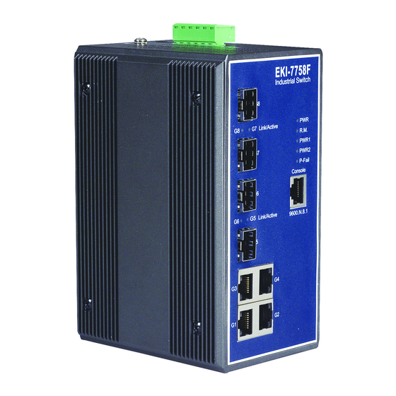
Chapter 2 Installation In this chapter, you will be given an overview of the EKI-7758F hardware installation procedures. 2.1 LED Indicators There are few LEDs display the power status and network status located on the front panel of EKI-7758F, each of them has its own specific meaning shown as below. -
Page 25: Dimensions (Units: Mm)
2.2 Dimensions (units: mm) Figure 2.1: Front View of EKI-7758F Chapter2... -
Page 26: Figure 2.2: Side View Of Eki-7758F
Figure 2.2: Side View of EKI-7758F EKI-7758F User Manual... -
Page 27: Figure 2.3: Rear View Of Eki-7758F
Figure 2.3: Rear View of EKI-7758F Chapter2... -
Page 28: Figure 2.4: Top View Of Eki-7758F
Figure 2.4: Top View of EKI-7758F EKI-7758F User Manual... -
Page 29: Mounting
The EKI-7758F supports two mounting methods: DIN-rail & Wall. 2.3.1 Wall mounting EKI-7758F can be wall-mounted by using the included mounting kit. Then, hang on the EKI-7758F to the nails on the wall. First, use the screws included in the package to combine the EKI-7758F and metal mounting kit. -
Page 30: Din-Rail Mounting
The DIN-rail kit is screwed on the industrial switch when out of factory. If the DIN-rail kit is not screwed on the industrial switch, please screw the DIN-rail kit on the switch first. First, hang the EKI-7758F to the DIN-rail with angle of inclination. See Figure 2.6. Figure 2.6: Installation to DIN-rail Step 1... -
Page 31: Figure 2.7: Installation To Din-Rail Step 2
Then, let the device down straight to slide over the rail smoothly. See Figure 2.7. Figure 2.7: Installation to DIN-rail Step 2 Chapter2... -
Page 32: Network Connection
2.4 Network Connection The EKI-7758F has 4 x RJ-45 ports that support connection to 10 Mbps Ethernet, 100 Mbps Fast Ethernet or 1000 Mbps Gigabit Ethernet. EKI-7758F can be connected to other hubs or switches through a twisted-pair straight cable or a crossover cable up to 100m long. -
Page 33: Figure 2.9: Transceiver Inserted
Figure 2.9: Transceiver Inserted Second, insert the fiber cable of LC connector into the transceiver. Figure 2.10: LC connector to the transceiver Chapter2... -
Page 34: Figure 2.11: Remove Lc Connector
First, press the upper side of the LC connector to release from the transceiver and pull it out. Figure 2.11: Remove LC connector Second, push down the metal loop and pull the transceiver out by the plastic handle. Figure 2.12: Pull out from the transceiver EKI-7758F User Manual... -
Page 35: Power Connection
2.6 Power Connection The EKI-7758F supports dual +12 ~ 48 V power inputs and power-fail relay output. Figure 2.8: Pin Assignment of the Power Connector You can connect an alarm indicator, buzzer or other signaling equipment through the relay output. The relay opens if power input 1, 2 fails or port link down/break (″Open″... - Page 36 EKI-7758F User Manual...
- Page 37 Configuration Sections include: RS-232 Console Web Browser Mounting Self Diagnosis Chapter3...
-
Page 38: Chapter 3 Configuration
Chapter 3 Configuration The EKI-7758F can be configured in two ways: via RS-232 Console or a web browser. 3.1 RS-232 Console EKI-7758F’s RS-232 console is designed for rapidly configuring which provides the console management – CLI command. Attach the supplied cable, which one end is RJ-45 and the other end is female DB9, to connect EKI- 7758F and your host PC or terminal. -
Page 39: Figure 3.2: Com Port Properties Setting
Select the appropriate COM port, and set the parameter as Fig.3.2 (9600 for Baud Rate, 8 for Data Bits, None for Parity, 1 for Stop Bits, and None for Flow Control). Figure 3.2: COM Port Properties Setting Press Enter for login screen (If you can not find the login screen, press Enter one more time). The default user name and password are both “admin”. -
Page 40: Figure 3.4: Command Line Interface
Use this mode to configure command (with a configuration mode, parameters for the switch and specific interface) enter exit. Ethernet ports. Interface switch(config-if)# while in global To exist to privileged configuration configuration mode EXEC mode, or end. EKI-7758F User Manual... -
Page 41: Commands Set List
3.1.2 Commands Set List Table 3.2: Commands Set List Command Code Word User EXEC Privileged EXEC Global configuration VLAN database Interface configuration 3.1.3 System Commands Set Table 3.3: System Commands Set Netstar Commands Level Description Example Show switch configuration switch>show config show config Show console information switch#show terminal... -
Page 42: Port Commands Set
1000 if the port isn’t a giga port.. Disable flow control of interface switch(config-if)#no flowcontrol no flowcontrol Enable security of interface switch(config)#interface fastEthernet 2 security enable switch(config-if)#security enable Disable security of interface switch(config)#interface fastEthernet 2 no security switch(config-if)#no security EKI-7758F User Manual... -
Page 43: Trunk Commands Set
Set interface ingress limit frame switch(config)#interface fastEthernet 2 bandwidth type all type to “accept all frame” switch(config-if)#bandwidth type all Set interface ingress limit frame switch(config)#interface fastEthernet 2 bandwidth type broadcast-multicast- type to “accept broadcast, switch(config-if)#bandwidth type broadcast- flooded-unicast multicast, and flooded unicast multicast-flooded-unicast frame”... -
Page 44: Vlan Commands Set
8021q port 3 hybrid-link untag 4 vlan 8021q port [PortNumber] port, if the port belong to a trunk tag 3,6,8 group, this command can’t be hybrid-link untag [UntaggedVID] applied. switch(vlan)#vlan 8021q port 3 hybrid-link untag 5 tag 6-8 [TaggedVID List] EKI-7758F User Manual... -
Page 45: Spanning Tree Commands Set
Assign a access link for VLAN by switch(vlan)#vlan 8021q trunk 3 access-link untag vlan 8021q trunk [PortNumber] trunk group access-link untag [UntaggedVID] Assign a trunk link for VLAN by trunk switch(vlan)#vlan 8021q trunk 3 trunk-link tag vlan 8021q trunk [PortNumber] group 2,3,6,99 trunk-link tag... -
Page 46: Qos Commands Set
Displays the details of an IGMP switch#show igmp multi show igmp multi snooping entries. Disable IGMP snooping function switch(config)#no igmp no igmp Disable IGMP query switch#no igmp-query no igmp-query 3.1.10 Mac/Filter Table Commands Set EKI-7758F User Manual... -
Page 47: Table 3.10: Mac/Filter Table Commands Set
Table 3.10: Mac/Filter Table Commands Set Netstar Commands Level Description Example Configure MAC address table of switch(config)#interface fastEthernet 2 mac-address-table static hwaddr [MAC] interface (static). switch(config-if)#mac-address-table static hwaddr 000012345678 Configure MAC address switch(config)#mac-address-table filter hwaddr mac-address-table filter hwaddr [MAC] table(filter) 000012348678 Show all MAC address table switch#show mac-address-table... -
Page 48: Port Mirroring Commands Set
8021x system radiousip 192.168.1.1 8021x system radiousip global configuration command to [IP address] change the radious server IP. Use the 802.1x system server port switch(config)# 8021x system serverport 1815 8021x system serverport global configuration command to [port ID] EKI-7758F User Manual... -
Page 49: Tftp Commands Set
change the radious server port Use the 802.1x system account switch(config)# 8021x system accountport 1816 8021x system accountport port global configuration command [port ID] to change the accounting port Use the 802.1x system share key switch(config)# 8021x system sharekey 123456 8021x system sharekey global configuration command to [ID]... -
Page 50: Sntp Commands Set
[IP] function is inactive, this command can’t be applied. Set timezone index, use “show switch(config)#sntp timezone 22 sntp timezone [Timezone] sntp timzezone” command to get more information of index number Show SNTP information switch#show sntp show sntp EKI-7758F User Manual... -
Page 51: X-Ring Commands Set
Show index number of time zone switch#show sntp timezone show sntp timezone list Disable SNTP function switch(config)#no sntp no sntp Disable daylight saving time switch(config)#no sntp daylight no sntp daylight 3.1.17 X-ring Commands Set Table 3.17: X-ring Commands Set Netstar Commands Level Description Example... -
Page 52: Web Browser
Your host PC should be in the same VLAN setting with EKI-7758F, or the management will not be configured. Connect EKI-7758F to the Ethernet then your host PC could configure it via Ethernet. Or you can directly connect EKI-7758F to your host PC with a straight-through or cross over Ethernet cable. -
Page 53: Figure 3.7: Main
In the main page, you can find the tree menu structure of the EKI-7758F in the left side. Click the “+” symbol to unroll the hiding hyperlink, and click the hyperlink to open the function page you want to configure. -
Page 54: Figure 3.8: System Information
• Gateway: Assign the network gateway for the industrial switch. The default gateway is 192.168.1.254. • DNS1: Assign the primary DNS IP address. • DNS2: Assign the secondary DNS IP address. • And then, click Apply EKI-7758F User Manual... -
Page 55: Figure 3.9: Ip Configuration
Figure 3.9: IP Configuration DHCP Server – System configuration The system provides the DHCP server function. Enable the DHCP server function, the switch system will be a DHCP server. • DHCP Server: Enable or Disable the DHCP Server function. Enable – the switch will be the DHCP server on your local network. -
Page 56: Figure 3.10: Dhcp Server - System Configuration
You can assign the specific IP address that is the IP in dynamic IP assign range to the specific port. When the device is connecting to the port and asks for dynamic IP assigning, the system will assign the IP address that has been assigned before to the connected device. EKI-7758F User Manual... -
Page 57: Figure 3.12: Dhcp Server – Client Entries
Figure 3.12: DHCP Server – Client Entries TFTP - Update Firmware It provides the functions to allow a user to update the switch firmware. Before updating, make sure you have your TFTP server ready and the firmware image is on the TFTP server. •... -
Page 58: Figure 3.14: Tftp – Restore Configuration
You can save current Flash ROM value from the switch to TFTP server, then go to the TFTP restore configuration page to restore the Flash ROM value. • TFTP Server IP Address: fill in the TFTP server IP • Backup File Name: fill the file name • Click Apply . EKI-7758F User Manual... -
Page 59: Figure 3.15: Tftp – Backup Configuration
Figure 3.15: TFTP – Backup Configuration System Event Log – Syslog Configuration Configuring the system event mode that want to be collected and system log server IP. • Syslog Client Mode: select the system log mode – client only, server only, or both S/C. •... -
Page 60: Figure 3.16: Syslog Configuration
SMTP Server IP Address column. • Password: The email account password. • Confirm Password: reconfirm the password. • Rcpt e-mail Address 1 ~ 6: you can assign up to 6 e-mail accounts also to receive the alert. • Click Apply . EKI-7758F User Manual... -
Page 61: Figure 3.17: Smtp Configuration
Figure 3.17: SMTP Configuration System Event Log - Event Configuration You can select the system log events and SMTP events. When selected events occur, the system will send out the log information. Also, per port log and SMTP events can be selected. After configure, Click Apply . -
Page 62: Figure 3.18: Event Configuration
• Power Failure: Mark the check box to enable the function of lighting up FAULT LED on the panel when power fails. • Port Link Down/Broken: Mark the check box to enable the function of lighting up FAULT LED on the panel when Ports’ states are link down or broken. EKI-7758F User Manual... -
Page 63: Figure 3.19: Fault Relay Alarm
Figure 3.19: Fault Relay Alarm SNTP Configuration You can configure the SNTP (Simple Network Time Protocol) settings. The SNTP allows you to synchronize switch clocks in the Internet. • SNTP Client: enable or disable SNTP function to get the time from the SNTP server. •... - Page 64 • Daylight Saving Period: set up the Daylight Saving beginning time and Daylight Saving ending time. Both will be different in every year. • Daylight Saving Offset (mins): set up the offset time. • Switch Timer: Displays the switch current time. • Click Apply . EKI-7758F User Manual...
-
Page 65: Figure 3.20: Sntp Configuration
Figure 3.20: SNTP Configuration IP Security IP security function allows user to assign 10 specific IP addresses that have permission to access the switch through the web browser for the securing switch management. • IP Security Mode: when this option is in Enable mode, the Enable HTTP Server and Enable Telnet Server check boxes will then be available. -
Page 66: Figure 3.21: Ip Security
• User name: Key in the new user name (The default is “admin”) • Password: Key in the new password (The default is “admin”) • Confirm password: Re-type the new password • And then, click Apply button to apply the configuration. EKI-7758F User Manual... -
Page 67: Figure 3.22: User Authentication
Figure 3.22: User Authentication Chapter3... -
Page 68: Port
• Duplex: set full-duplex or half-duplex mode of the port. • Flow Control: set flow control function is Symmetric or Asymmetric in Full Duplex mode. The default value is Symmetric. • Security: when its state is “On” that means this port accepts only one MAC address. EKI-7758F User Manual... -
Page 69: Figure 3.24: Port Control
• Click Apply button to apply the configuration. Figure 3.24: Port Control Port Trunk The Link Aggregation Control Protocol (LACP) provides a standardized means for exchanging information between Partner Systems on a link to allow their Link Aggregation Control instances to reach agreement on the identity of the Link Aggregation Group to which the link belongs, move the link to that Link Aggregation Group, and enable its transmission and reception functions in an orderly manner. -
Page 70: Figure 3.25: Aggregator Setting
When you had setup the LACP aggregator, you can configure port state activity. You can mark or un- mark the port. When you mark the port and click Apply button the port state activity will change to Active. Opposite is Passive. EKI-7758F User Manual... -
Page 71: Figure 3.27: State Activity
• Active: The port automatically sends LACP protocol packets. • Passive: The port does not automatically send LACP protocol packets, and responds only if it receives LACP protocol packets from the opposite device. Note A link having either two active LACP ports or one active port can perform dynamic LACP trunk. -
Page 72: Figure 3.28: Port Mirroring
• Ingress: Enter the port effective ingress rate (The default value is “0”) • Egress: Enter the port effective egress rate (The default value is “0”) • And then, click Apply to apply the settings EKI-7758F User Manual... -
Page 73: Figure 3.29: Rate Limiting
Figure 3.29: Rate Limiting Chapter3... -
Page 74: Protocol
VLAN tags or attached to a VLAN-aware bridge that is capable of classifying and tagging the packet with different VLAN ID based on not only default PVID but also other information about the packet, such as the protocol. EKI-7758F User Manual... -
Page 75: Figure 3.31: Port Based Mode
Figure 3.31: Port based mode • Pull down the select item menu of VLAN Operation Mode, and select Port Based mode. • Click to add a new VLAN group(The maximum VLAN group is up to 64 VLAN groups) • Entering the VLAN name, group ID and grouping the members of VLAN group •... -
Page 76: Figure 3.32: Port Based Mode-Add Interface
GVRP allows automatic VLAN configuration between the switch and nodes. If the switch is connected to a device with GVRP enabled, you can send a GVRP request using the VID of a VLAN defined on the switch; the switch will automatically add that device to the existing VLAN. EKI-7758F User Manual... -
Page 77: Figure 3.33: 802.1Q Vlan Configuration
Figure 3.33: 802.1Q VLAN Configuration 802.1Q Configuration • Pull down the select item menu of VLAN Operation Mode, and select Port Based mode. • Enable GVRP Protocol: mark the check box to enable GVRP protocol that allows network devices to dynamically exchange VLAN configuration information with other devices. -
Page 78: Figure 3.34: Edit Group Configuration Interface
Figure 3.34: Edit Group Configuration interface • You can Change the VLAN group name and VLAN ID. • Click Apply . Figure 3.35: Apply Group Configuration interface EKI-7758F User Manual... -
Page 79: Figure 3.36: Rstp System Configuration Interface
Rapid Spanning Tree The Rapid Spanning Tree Protocol (RSTP) is an evolution of the Spanning Tree Protocol and provides for faster spanning tree convergence after a topology change. The system also supports STP and the system will auto detect the connected device that is running STP or RSTP protocol. RSTP - System Configuration •... -
Page 80: Figure 3.37: Rstp Port Configuration Interface
“True” status. • Non Stp: The port includes the STP mathematic calculation. True is not including STP mathematic calculation. False is including the STP mathematic calculation. • Click Apply . Figure 3.37: RSTP Port Configuration interface EKI-7758F User Manual... -
Page 81: Figure 3.38: Snmp System Configuration Interface
SNMP Configuration Simple Network Management Protocol (SNMP) is the protocol developed to manage nodes (servers, workstations, routers, switches and hubs etc.) on an IP network. SNMP enables network administrators to manage network performance, find and solve network problems, and plan for network growth. Network management systems learn of problems by receiving traps or change notices from network devices implementing SNMP. -
Page 82: Figure 3.39: Trap Configuration Interface
• User ID: set up the user name. • Authentication Password: set up the authentication password. • Privacy Password: set up the private password. • Click Add to add context name. • Click Remove to remove unwanted context name. EKI-7758F User Manual... -
Page 83: Figure 3.40: Snmp V3 Configuration Interface
Figure 3.40: SNMP V3 Configuration interface Group Table Configure SNMP v3 group table. • Security Name (User ID): Assign the user name that you have set up in user table. • Group Name: Set up the group name. • Click Add to add context name. •... - Page 84 • ViewName: Set up the name. • Sub-Oid Tree: Fill the Sub OID. • Type: Select the type – exclude or included. • Click Add to add context name. • Click Remove to remove unwanted context name. EKI-7758F User Manual...
- Page 85 QoS Configuration You can configure Qos policy and priority setting, per port priority setting, COS and TOS setting. QoS Policy and Priority Type • Qos Policy: select the Qos policy rule. Use an 8,4,2,1 weighted fair queuing scheme: The switch will follow 8:4:2:1 rate to process priority queue from High to Lowest queue.
-
Page 86: Figure 3.41: Qos Configuration Interface
• Port 1 ~ Port 10: each port has 4 priority levels – High, Middle, Low, and Lowest. • Click Apply . COS Configuration Set up the COS priority level. • COS priority: Set up the COS priority level 0~7 –High, Middle, Low, Lowest. • Click Apply . EKI-7758F User Manual... -
Page 87: Table 3.19: Igmp Types
TOS Configuration Set up the TOS priority. • TOS priority: the system provides 0~63 TOS priority level. Each level has 4 types of priority – high, middle, low, and lowest. The default value is “Lowest” priority for each level. When the IP packet is received, the system will check the TOS level value in the IP packet that has received. -
Page 88: Figure 3.42: Igmp Configuration Interface
• Enable Dual Homing: Set up one of port on the switch to be the Dual Homing port. In an X-Ring group, maximum Dual Homing port is one. Dual Homing only work when the X-Ring function enable. EKI-7758F User Manual... -
Page 89: Figure 3.43: X-Ring Interface
• Enable Dual Ring: When this check box is marked, the ‘Enable Ring Master’ check box will then also be enabled by the system which means this equipment is assigned as the Ring Master. The Dual Ring differs from the Couple Ring in that it only needs a unit to form a redundant linking system of two rings. •... -
Page 90: Security
• Authorized: the specified port is set to the Authorized or Unauthorized state in accordance with the outcome of an authentication exchange between the Supplicant and the authentication server. • Disable: The specified port is required to be held in the Authorized state • Click Apply . EKI-7758F User Manual... -
Page 91: Figure 3.45: 802.1X/Radius - Port Setting Interface
Figure 3.45: 802.1x/Radius - Port Setting interface 802.1X/Radius - Misc Configuration • Quiet Period: set the period during which the port doesn’t try to acquire a supplicant. • TX Period: set the period the port wait for retransmit next EAPOL PDU during an authentication session. -
Page 92: Figure 3.47: Static Mac Addresses Interface
Figure 3.47: Static MAC Addresses interface MAC Address Table - MAC Filtering By filtering MAC address, the switch can easily filter pre-configure MAC address and reduce the un- safety. You can add and delete filtering MAC address. EKI-7758F User Manual... -
Page 93: Figure 3.48: Mac Filtering Interface
Figure 3.48: MAC Filtering interface • MAC Address: Enter the MAC address that you want to filter. • Click • If you want to delete the MAC address from filtering table, select the MAC address and click Delete . MAC Address Table - All MAC Addresses You can view the port that connected device’s MAC address and related devices’... -
Page 94: Figure 3.50: Factory Default Interface
Save all configurations that you have made in the system. To ensure the all configuration will be saved. Click Save to save the all configuration to the flash memory. Figure 3.51: Save Configuration interface System Reboot Reboot the switch in software reset. Click Reboot to reboot the system. EKI-7758F User Manual... -
Page 95: Figure 3.52: System Reboot Interface
Figure 3.52: System Reboot interface Chapter3... - Page 96 EKI-7758F User Manual...
- Page 97 Troubleshooting...
-
Page 98: Chapter 4 Troubleshooting
If user still cannot resolve the problem, contact the local dealer for assistance. If the Industrial switch LED indicators are normal and the connected cables are correct but the packets still cannot transmit, please check your system’s Ethernet devices configuration or status. EKI-7758F User Manual... - Page 99 Pin Assignment & Wiring...
-
Page 100: Figure A.1: Rj-45 Pin Assignment
Appendix A Pin Assignment & Wiring It is suggested to adopt ELA/TIA as the wiring of the RJ-45. Figure A.1: RJ-45 Pin Assignment Figure A.2: EIA/TIA-568B Figure A.3: EIA/TIA-568A EKI-7758F User Manual... -
Page 101: Figure A.4: Db 9-Pin Female Connector
Figure A.4: DB 9-pin female connector DB9 Connector RJ-45 Connector 1 Orange/White 2 Orange 3 Green/White 4 Blue 5 Blue/White 6 Green 7 Brown/White 8 Brown... - Page 102 EKI-7758F User Manual...
- Page 103 Compatible SFP Modules...
-
Page 104: Compatible Sfp Modules
Appendix B Compatible SFP Modules The table below shows compatible SFP modules for EKI-7758F. Transmission Item Brand Part Number Mode Distance AVAGO AFBR-5710PZ 550m APAC LM28-C3S-TC-N 550m Multi-mode HOATECH HTI8512-X5ATO 550m SPACE SHUTTLE S56L-S85-6L-N 550m SP-GB-LX 10km LuminentOIC SP-GB-ELX 20km... - Page 105 X-View...
-
Page 106: Appendix C X-View
‘Task’ in the top menu bar, a pull-down menu shows up which including: Discovery, Discovery Filter, Login, Reboot, Refresh, Refresh All and Exit items. Figure C.2: Items to the ‘Task’ menu bar • Discovery: Click the mouse point on ‘Discovery’ item or press ‘Ctrl+D’ to search EKI-7758F User Manual... -
Page 107: Figure C.3: Two Devices Have Been Discovered
the managed devices on your LAN. Here is an example screenshot: Figure C.3: Two devices have been discovered • Discovery Filter: Click the mouse pointer on ‘Discovery Filter’ item or press ‘Ctrl+F’ to set the ‘Discovery Type’. Here is an example screenshot: Figure C.4: Discovery Filter setting window There is a radio button group of three selections to set the discovery type. -
Page 108: Figure C.5: Login Interface
Select any one of the devices in the left tree menu field; the login interface (User Name/Password) on the right side will subsequently be available (see the figure below). Figure C.6: User Name/Password interface • Reboot: Click the mouse pointer on ‘Reboot’ in the top menu bar. EKI-7758F User Manual... -
Page 109: Figure C.7: Reboot Function
Figure C.7: Reboot function Select any one of the devices in the left tree menu field; the reboot button on the right side will subsequently be available (see the figure below). Figure C.8: Press Reboot button to restart the switch •... -
Page 110: Figure C.9: Refresh For Single Function
Figure C.9: Refresh for single function • Refresh All: Click the mouse pointer on ‘Refresh All’ in the top menu bar to refresh all the information of the switch. Figure C.10: Refresh all the information EKI-7758F User Manual... -
Page 111: Figure C.11: Log Displaying Information
You can also make a check of the log by clicking on the ‘Log tab’ on the right side. Figure C.11: Log displaying information... -
Page 112: C.1 System
DHCP client function. When DHCP client function is enabled, the industrial switch will be assigned an IP address from the network DHCP server. The default IP address will be replaced by the assigned IP address from DHCP server. EKI-7758F User Manual... -
Page 113: Figure C.13: Ip Configuration—Dhcp
After user click “Apply” button, a popup dialog shows up to ask user entering user name and password. Figure C.13: IP Configuration—DHCP • Auto Range: When the Method is selected as Auto Range, you can fill in the IP addresses for IP Begin, IP End, Subnet Mask, Gateway, DNS Server1 and DNS Server2 column fields to assign a range of IP addresses. -
Page 114: Figure C.15: Ip Configuration—Manual
• Lease Time (sec): It is the time period that system will reset the dynamic IP assignment to ensure the dynamic IP will not been occupied for a long time or the server doesn’t know that the dynamic IP is idle. EKI-7758F User Manual... -
Page 115: Figure C.16: Dhcp Server Interface
Figure C.16: DHCP Server interface Client Entries When the DHCP server function is active, the system will collect the DHCP client information and displays it here. Figure C.17: DHCP Server – Client Entries Port and IP Binding You can assign the specific IP address that is one of the IP addresses in dynamic IP assigning range to the specific port. -
Page 116: Figure C.18: Dhcp Server – Port And Ip Binding
• Use build-in support: Click the mouse pointer on the ‘Open’ button to locate file via explorer window. Figure C.19: TFTP Transaction – Upgrade 1 • Use remote tftp server: Enter the IP address of the TFTP server and the firmware file name. EKI-7758F User Manual... -
Page 117: Figure C.20: Tftp Transaction – Upgrade 2
Figure C.20: TFTP Transaction – Upgrade 2 Restore You can restore Flash ROM value from TFTP server, but you must put the image file on TFTP server first, switch will download back flash image. • Use build-in support: Click the mouse pointer on the ‘Open’ button to locate file via explorer window. -
Page 118: Figure C.22: Tftp Transaction – Restore 2
• Use build-in support: Click the mouse pointer on the ‘Save’ button to locate a path via explorer window for saving the backup file. Figure C.23: TFTP Transaction – Backup 1 • Use remote tftp server: Enter the IP address of the TFTP server and the firmware file name. EKI-7758F User Manual... -
Page 119: Figure C.24: Tftp Transaction – Backup 2
Figure C.24: TFTP Transaction – Backup 2 C.1.5 System Event Log Syslog Configuration Configuring the system event mode you want to collect and system log server IP. • Mode: select the system log mode – Client Only, Server Only, or Both. •... -
Page 120: Figure C.26: Syslog Table
SMTP Server IP Address column. • Password: The email account password. • Confirm Password: reconfirm the password. • Recipients’ E-mail: you can assign up to 6 e-mail accounts to receive the alert. EKI-7758F User Manual... -
Page 121: Figure C.28: Event Configuration
Event Configuration You can select the ‘Syslog’ and ‘SMTP’ events. When selected events occur, the system will send out the log information. Also, per port log and SMTP events can be selected. After configuring, Click ‘Apply’. • System Event selection: 4 selections – Device cold start, Device warm start, SNMP Authentication Failure, and X-ring topology change. -
Page 122: Figure C.29: Event Configuration
• Security IP 1 ~ 10: Assign up to 10 specific IP address. Only these 10 IP address can access and manage the switch through the Web browser • And then, click ‘Apply’ button to apply the configuration. EKI-7758F User Manual... -
Page 123: Figure C.30: Ip Security
Figure C.30: IP Security Note Remember to execute the “Save Configuration” action, otherwise the new configuration will lose when switch power off. C.1.8 User Authentication Change web management login user name and password for the management security issue. • User name: Key in the new user name (The default is “admin”) •... -
Page 124: C.2 Port
• Speed/Duplex: set the port link speed. • Duplex: set full-duplex or half-duplex mode of the port. • Flow Control: set flow control function is Symmetric or Asymmetric in Full Duplex mode. The default value is Symmetric. EKI-7758F User Manual... -
Page 125: Figure C.33: Port Control
• Security: when its state is “On” that means this port accepts only one MAC address. • Click ‘Apply’ button to apply the configuration. Figure C.33: Port Control C.2.3 Port Status In Port Status, you can view every port status that depends on user setting and the negotiation result. -
Page 126: C.2.4 Port Trunk
If it is static trunk group, the number of ports must be the same as the group member ports. • Click ’Apply’ button to carry the setting into effect. Figure C.35: Port Trunk Port Trunk Status: This function displays the Group ID, Trunk Member and Type. EKI-7758F User Manual... -
Page 127: Figure C.36: Port Trunk Status
Figure C.36: Port Trunk Status C.2.5 Port Mirroring The Port mirroring is a method for monitor traffic in switched networks. Traffic through ports can be monitored by one specific port. That means traffic goes in or out monitored (source) ports will be duplicated into mirror (destination) port. •... -
Page 128: Figure C.38: Rate Limiting
• Ingress: Enter the port effective ingress rate (The default value is “8192”) • Egress: Enter the port effective egress rate (The default value is “0”) • And then, click ‘Apply’ to apply the settings. Figure C.38: Rate Limiting EKI-7758F User Manual... -
Page 129: C.3 Protocol
C.3 Protocol C.3.1 VLAN VLAN configuration A Virtual LAN (VLAN) is a logical network grouping that limits the broadcast domain, which would allow you to isolate network traffic, so only the members of the VLAN will receive traffic from the same members of VLAN. Basically, creating a VLAN from a switch is logically equivalent of reconnecting a group of network devices to another Layer 2 switch. -
Page 130: Figure C.40: 802.1Q Vlan
Figure C.40: 802.1Q VLAN Port Configuration Set Port No., Link Type, Untagged VID, and Tagged VIDs then click ‘Apply’ button to apply. Figure C.41: Port Configuration VLAN Table This function displays the VLAN table information. EKI-7758F User Manual... -
Page 131: Figure C.42: Vlan Table
Figure C.42: VLAN Table Port-based VLAN Packets can go among only members of the same VLAN group. Note all unselected ports are treated as belonging to another single VLAN. If the port-based VLAN enabled, the VLAN-tagging is ignored. In order for an end station to send packets to different VLAN groups, it itself has to be either capable of tagging packets it sends with VLAN tags or attached to a VLAN-aware bridge that is capable of classifying and tagging the packet with different VLAN ID based on not only default PVID but also other information about the packet, such as the... -
Page 132: C.3.2 Rapid Spanning Tree
To configure the port as an edge port, set the port to “True” status. • Non Stp: The port includes the STP mathematic calculation. True is not including STP mathematic calculation. False is including the STP mathematic calculation. • Click ’Apply’. EKI-7758F User Manual... -
Page 133: Figure C.44: Rstp
Figure C.44: RSTP Note Follow the rule to configure the MAX Age, Hello Time, and Forward Delay Time. 2 x (Forward Delay Time value –1) > = Max Age value >= 2 x (Hello Time value +1) RSTP - Port Configuration Here you can view the RSTP information. -
Page 134: Figure C.46: Snmp
• Privilege: ‘Read only’ enables requests that accompanied by this string to display MIB-object information. ‘Read and Write’ enables requests accompanied by this string to display MIB-object information and to set objects. • Click ’Apply’. Trap Configuration EKI-7758F User Manual... -
Page 135: Figure C.48: Trap Configuration
A trap manager is a management station that receives traps, the system alerts generated by the switch. If no trap manager is defined, no traps will issue. Create a trap manager by entering the IP address of the station and a community string. To define management stations as trap manager and enter SNMP community strings and selects the SNMP version. -
Page 136: Figure C.50: Snmpv3 User Table
• Security Name (User ID): Assign the user name that you have set up in user table. • Group Name: Set up the group name. • Click ‘Add’ to add context name. • Click ‘Delete’ to remove unwanted context name. Figure C.51: SNMPv3 Group Table EKI-7758F User Manual... -
Page 137: Figure C.52: Snmpv3 Access Table
SNMPv3 Access Table Configure SNMP v3 access table. Figure C.52: SNMPv3 Access Table • Context Prefix: Set up the context name. • Group Name: Set up the group. • Security Level: Set up the access level. • Context Match Rule: Select the context match rule. •... -
Page 138: Figure C.53: Snmpv3 Mibview Table
TOS only: the port priority will only follow the TOS priority that you have assigned. COS first: the port priority will follow the COS priority first, and then other priority rule. TOS first: the port priority will follow the TOS priority first, and the other priority rule. • Click ‘Apply’. EKI-7758F User Manual... -
Page 139: Figure C.54: Qos
Figure C.54: QoS Port Base Priority Configure per port priority level. • Port 1 ~ Port 10: each port has 4 priority levels – High, Middle, Low, and Lowest. • Click ‘Apply’. Figure C.55: Port Based Priority COS Settings Set up the COS priority level. •... -
Page 140: Figure C.56: Cos Settings
TOS value of the received IP packet. If the TOS value of received IP packet is 25(priority = high), and then the packet priority will have highest priority. • Click ‘Apply’. Figure C.57: TOS Settings EKI-7758F User Manual... -
Page 141: Figure C.58: Igmp
IGMP Configuration The Internet Group Management Protocol (IGMP) is a communications protocol used to manage the membership of Internet Protocol multicast groups. IGMP is used by IP hosts and adjacent multicast routers to establish multicast group memberships. It is an integral part of the IP multicast specification, like ICMP for unicast connections. -
Page 142: Figure C.59: Igmp Snooping Table
• Enable Dual Homing: Set up one of port on the switch to be the Dual Homing port. In an X-Ring group, maximum Dual Homing port is one. Dual Homing only work when the X-Ring function enable. EKI-7758F User Manual... -
Page 143: Figure C.60: X-Ring
• And then, click ‘Apply’ to apply the configuration. Figure C.60: X-Ring... -
Page 144: C.4 Security
• Max Requests: set the number of authentication that must time-out before authentication fails and the authentication session ends. • Reauth period: set the period of time after which clients connected must be re- authenticated. • Click ‘Apply’. EKI-7758F User Manual... -
Page 145: Figure C.61: 802.1X/Radius
Figure C.61: 802.1x/RADIUS Port Auth You can configure 802.1x authentication state for each port. The State provides Disable, Accept, Reject and Authorize. • Reject: the specified port is required to be held in the unauthorized state. • Accept: the specified port is required to be held in the Authorized state. •... -
Page 146: Figure C.63: Static Mac Address
You can add and delete filtering MAC address via this function. • MAC Address: Enter the MAC address that you want to filter. • Click ‘Add’. • If you want to delete the MAC address from filtering table, select the MAC address and click ‘Delete’. EKI-7758F User Manual... -
Page 147: Figure C.64: Mac Filtering
Figure C.64: MAC Filtering All MAC Addresses You can view the port of connected device’s MAC address and related devices’ MAC address. • Select the port. • The selected port of the static MAC address information will be displayed here. •... -
Page 148: C.5 Factory Default
C.6 Save To Flash Save all configurations that you have made in the system. To ensure the all configuration will be saved. Click ‘Save’ button to save the entire configuration to the flash memory. Figure C.67: Save to Flash EKI-7758F User Manual... -
Page 149: Figure C.68: System Reboot
C.7 System Reboot Reboot the switch in software reset. Click ‘Reboot’ button to reboot the system. Figure C.68: System Reboot...
Need help?
Do you have a question about the EKI-7758F and is the answer not in the manual?
Questions and answers