Sign In
Upload
Manuals
Brands
INVT Manuals
Inverter
Goodrive350 Series
User Manuals: INVT Goodrive350 Series Drive
Manuals and User Guides for INVT Goodrive350 Series Drive. We have
6
INVT Goodrive350 Series Drive manuals available for free PDF download: Operation Manual
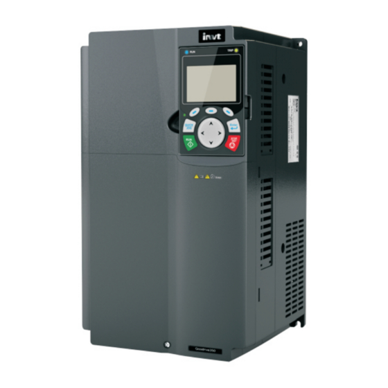
INVT Goodrive350 Series Operation Manual (429 pages)
High-performance multifunction VFD
Brand:
INVT
| Category:
DC Drives
| Size: 21 MB
Table of Contents
Table of Contents
3
Safety Precautions
10
What this Chapter Contains
10
Safety Definition
10
Warning Symbols
10
Safety Guidelines
11
Delivery and Installation
11
Commissioning and Running
12
Maintenance and Component Replacement
13
What to Do after Scrapping
13
Quick Startup
14
What this Chapter Contains
14
Unpack Inspection
14
Application Confirmation
14
Environment Confirmation
14
Installation Confirmation
15
Basic Commissioning
15
Safety Standard Related Data
16
Product Overview
17
What this Chapter Contains
17
Basic Principle
17
Product Specifications
19
Product Nameplate
21
Type Designation Key
21
Ratings of a Single Product
22
Parallel Products
24
Ratings of Parallel Products
24
Structure Diagram
25
Installation Guidelines
26
What this Chapter Contains
26
Mechanical Installation
26
Installation Environment
26
Installation Direction
27
Installation Mode
28
Single-Product Installation
28
Multiple-Product Installation
29
Vertical Installation
30
Tilted Installation
31
Standard Wiring of Main Circuit
32
Wiring Diagram of Main Circuit for a Single Product
32
Wiring Diagram of Main Circuit for Parallel Products
33
Main Circuit Terminal Diagram
34
Wiring Procedure of the Main Circuit Terminals
37
Standard Wiring of Control Circuit
38
Wiring Diagram of Basic Control Circuit
38
Wiring Diagram of Control Circuit for Parallel Products
40
Input/Output Signal Connection Diagram
41
Wiring Protection
42
Protect the VFD and Input Power Cable in Short-Circuit
42
Protect the Motor and Motor Cable in Short Circuit
42
Protect Motor and Prevent Thermal Overload
42
Bypass Connection
42
Basic Operation Guidelines
43
What this Chapter Contains
43
Keypad Introduction
43
Keypad Display
46
Displaying Stopped-State Parameters
46
Displaying Running-State Parameters
47
Displaying Fault Information
48
Operating the VFD through the Keypad
48
Entering/Exiting Menus
48
Editing a Parameter List
53
Adding Parameters to the Parameter List Displayed in Stopped/Running State
54
Adding Parameters to the User Defined Parameter List
54
Editing User Defined Parameters
55
Editing Parameters in Parameter Groups
56
Monitoring States
56
Autotuning Motor Parameters
57
Backing up Parameters
57
System Settings
58
Power-On Setup Wizard
58
Basic Operations
59
What this Section Contains
59
Common Commissioning Procedures
60
Vector Control
63
SVPWM Control Mode
68
Torque Control
77
Motor Parameter
82
Start/Stop Control
87
Frequency Setup
92
Analog Input
96
Analog Output
99
Digital Input
104
Digital Output
113
Simple PLC
118
Multi-Step Speed Running
121
PID Control
122
Run at Wobbling Frequency
128
Local Encoder Input
129
Commissioning Procedures for Closed-Loop Control, Position Control and Spindle Positioning
130
Fault Handling
135
Tension Control Solutions
140
Function Parameter List
145
What this Chapter Contains
145
P00--Basic Functions
146
P01--Start/Stop Control
150
P02--Parameters of Motor 1
156
P03--Vector Control of Motor 1
160
P04--V/F Control
167
P05--Input Terminals
175
P06--Output Terminals
184
P07--Hmi
188
P08--Enhanced Functions
195
P09--PID Control
202
P10--Simple PLC and Multi-Step Speed Control
207
P11--Protection Parameters
210
P12--Parameters of Motor 2
218
P13--Control Parameters of Synchronous Motor
221
P14--Serial Communication Function
223
P15--Functions of Communication Expansion Card 1
228
P16--Functions of Communication Expansion Card 2
231
P17--Status Viewing
236
P18--Closed-Loop Control State Check
241
P19--Expansion Card State Check
244
P20--Encoder of Motor 1
246
P21--Position Control
250
P22--Spindle Positioning
256
P23--Vector Control of Motor 2
259
P24--Encoder of Motor 2
261
P25--Expansion I/O Card Input Functions
265
P26--Output Functions of Expansion I/O Card
268
P27--Programmable Expansion Card Functions
271
P28--Master/Slave Control Functions
274
P90--Tension Control in Speed Mode
277
P91--Tension Control in Torque Mode
281
P92--Customized Tension Control Functions
284
P93--Tension Control Status Viewing
286
Troubleshooting
289
What this Chapter Contains
289
Indications of Alarms and Faults
289
Fault Reset
289
Fault History
289
VFD Faults and Solutions
289
Details of Faults and Solutions
289
Other State
298
Analysis on Common Faults
298
Motor Fails to Work
298
Motor Vibrates
299
Overvoltage
300
Undervoltage
300
Unusual Heating of Motor
301
VFD Overheating
302
Motor Stalls During ACC
303
Overcurrent
304
Countermeasures on Common Interference
305
Interference on Meter Switches and Sensors
305
Interference on Communication
306
Failure to Stop and Indicator Shimmering Due to Motor Cable Coupling
307
Leakage Current and Interference on RCD
307
Live Device Chassis
308
Maintenance and Hardware Fault Diagnosis
309
What this Chapter Contains
309
Periodical Inspection
309
Cooling Fan
311
Capacitor
312
Capacitor Reforming
312
Electrolytic Capacitor Replacement
313
Power Cable
313
Communication
315
What this Chapter Contains
315
Modbus Protocol Introduction
315
Application of Modbus
315
Rs485
315
RTU Mode
318
RTU Command Code and Communication Data
321
Command Code 03H, Reading N Words (Continuously up to 16 Words)
321
Command Code 06H, Writing a Word
323
Command Code 08H, Diagnosis
323
Command Code 10H, Continuous Writing
324
Data Address Definition
325
Fieldbus Scale
329
Error Message Response
330
Read/Write Operation Example
332
Common Communication Faults
337
Appendix A Expansion Cards
338
Model Definition
338
Dimensions and Installation
346
Wiring
348
IO Expansion Cards
349
IO Expansion Card 1 (EC-IO501-00)
349
IO Expansion Card 2 (EC-IO502-00)
351
Programmable Expansion Card (EC-PC502-00)
353
Communication Cards
356
Bluetooth Communication Card (EC-TX501) and WIFI Communication Card (EC-TX502)
356
PROFIBUS-DP Communication Card (EC-TX503)
358
Ethernet Communication Card (EC-TX504)
359
Canopen Communication Card (EC-TX505) and CAN Master/Slave Control
360
Communication Card (EC-TX511)
360
PROFINET Communication Card (EC-TX509)
361
Ethernet/Ip Communication Card (EC-TX510) and Modbus TCP Communication Card (EC-TX515)
363
PG Cards
365
Sin/Cos PG Card (EC
365
UVW Incremental PG Card (EC
368
Resolver PG Card (EC
370
Multifunction Incremental PG Card (EC
372
Incremental PG Card (EC
376
Simplified Incremental PG Card (EC
379
Simplified Incremental PG Card (EC
380
GPRS Card (EC-IC501-2)
384
Appendix B Technical Data
385
What this Chapter Contains
385
Derated Application
385
Capacity
385
Derating
385
Advertisement
INVT Goodrive350 Series Operation Manual (418 pages)
IP55 High-ingress Protection VFD
Brand:
INVT
| Category:
DC Drives
| Size: 26 MB
Table of Contents
Table of Contents
5
Safety Precautions
12
Safety Definition
12
Warning Symbols
12
Safety Guidelines
13
Delivery and Installation
13
Commissioning and Running
14
Maintenance and Component Replacement
15
Disposal
15
Quick Startup
16
What this Chapter Contains
16
Unpacking Inspection
16
Checking before Use
16
Environment Checking
16
Checking after Installation
17
Basic Commissioning
18
Safety Standard Related Data
18
What this Chapter Contains
19
Product Overview
19
Basic Principles
19
Product Specifications
20
Product Nameplate
22
Model Designation Code
23
Product Ratings
23
Structure
24
Installation Guidelines
26
What this Chapter Contains
26
Mechanical Installation
26
Installation Environment
26
Installation Direction
27
Installation Method
28
Installing One Unit
28
Multiple-Product Installation
29
Vertical Installation
30
Tilted Installation
31
Standard Wiring of the Main Circuit
32
Main Circuit Wiring Diagrams
32
Main Circuit Terminal Diagram
33
Wiring Procedure of Main Circuit Terminals
36
Standard Wiring of the Control Circuit
37
Wiring Diagram of Basic Control Circuit
37
Input/Output Signal Connection Diagram
39
Wiring Protection
40
Protecting the VFD and Input Power Cable in Case of Short Circuit
40
Protecting the Motor and Motor Cable in Case of Short Circuit
41
Protecting the Motor against Thermal Overload
41
Bypass Connection
41
Basic Operation Guidelines
42
What this Chapter Contains
42
Keypad Introduction
42
Keypad Display
45
Displaying Stopped-State Parameters
45
Displaying Running-State Parameters
46
Displaying Fault Alarms
47
Operation Procedure
47
Entering/Exiting Menus
47
Editing List
52
Adding Parameters to the Parameter List Displayed in Stopped/Running State
53
Adding Parameters to the User Defined Parameter Setting List
54
Editing User Defined Parameters
54
Editing Parameters in Parameter Groups
55
Monitoring States
55
Autotuning Motor Parameters
56
Parameter Backup
57
System Settings
57
Power-On Guiding Settings
57
Basic Operation Description
58
What this Section Describes
58
Common Commissioning Procedure
59
Vector Control
62
Space Voltage Vector Control Mode
68
Torque Control
76
Motor Parameters
79
Start/Stop Control
84
Frequency Setting
89
Analog Input
93
Analog Output
96
Digital Input
100
Digital Output
109
Simple PLC
114
Multi-Step Speed Running
117
PID Control
118
Run at Wobbling Frequency
124
Local Encoder Input
125
Commissioning Procedures for Closed-Loop Control, Position Control and Spindle Positioning
126
Fault Handling
133
Tension Control Solutions
137
Function Parameter List
142
What this Chapter Contains
142
Group P00-Basic Functions
143
Group P01--Start and Stop Control
147
Group P02-Parameters of Motor 1
154
Group P03--Vector Control of Motor 1
157
Group P04-V/F Control
163
Group P05--Input Terminal Functions
171
Group P06-Output Terminal Functions
179
Group P07--Human-Machine Interface
184
Group P08-Enhanced Functions
191
Group P09-PID Control
199
Group P10-Simple PLC and Multi-Step Speed Control
204
Group P11--Protection Parameters
207
Group P12--Parameters of Motor 2
215
Group P13-SM Control
218
Group P14-Serial Communication
219
Group P15--Communication Expansion Card 1 Functions
224
Group P16--Communication Expansion Card 2 Functions
227
Group P17-Status Viewing
232
Group P18--Status Viewing in Closed-Loop Control
237
Group P19-Expansion Card Status Viewing
239
Group P20--Encoder of Motor 1
241
Group P21--Position Control
245
Group P22--Spindle Positioning
252
Group P23--Vector Control of Motor 2
255
Group P24--Encoder of Motor 2
257
Group P25--I/O Card Input Functions
261
Group P26--I/O Card Output Functions
264
Group P27--Programmable Expansion Card Functions
266
Group P28--Master/Slave Control
269
Group P90--Tension Control
273
Group P91--Tension Control in Torque Mode
277
Group P92--Tension Control Optimization Functions
280
Group P93--Tension Control Status Viewing
281
Troubleshooting
284
What this Chapter Contains
284
Indications of Alarms and Faults
284
Fault Reset
284
Fault History
284
Faults and Solutions
284
Other Status
293
Analysis on Common Faults
293
Motor Fails to Work
293
Motor Vibrates
294
Overvoltage
295
Undervoltage
295
Motor Overheating
296
VFD Overheating
297
Motor Stalls During ACC
298
Overcurrent
299
Countermeasures on Common Interference
299
Interference on Meter Switches and Sensors
299
Interference on RS485 Communication
301
Failure to Stop and Indicator Shimmering Due to Motor Cable Coupling
302
Leakage Current and Interference on RCD
302
Live Device Chassis
303
Maintenance
305
What this Chapter Contains
305
Periodical Inspection
305
Cooling Fan
307
Capacitor
308
Capacitor Reforming
308
Electrolytic Capacitor Replacement
310
Power Cable
310
Communication Protocol
311
What this Chapter Contains
311
Modbus Protocol Introduction
311
Application of Modbus
311
Rs485
311
RTU Mode
314
RTU Command Code and Communication Data
317
Command Code 03H, Reading N Words (Continuously up to 16 Words)
317
Command Code 06H, Writing a Word
319
Command Code 10H, Continuous Writing
320
Data Address Definition
321
Fieldbus Scale
325
Error Message Response
326
Read/Write Operation Examples
328
Common Communication Faults
333
Appendix A Expansion Card
334
Model Definition
334
Dimensions and Installation
345
Wiring
347
I/O Expansion Cards
348
I/O Expansion Card 1 (EC-IO501-00)
348
IO Expansion Card 2 (EC-IO502-00)
350
Programmable Extension Card (EC-PC502-00)
352
Communication Cards
355
Bluetooth Communication Card (EC-TX501) and WIFI Communication Card (EC-TX502)
355
PROFIBUS-DP Communication Card (EC-TX503D)
357
CAN Multi-Protocol Communication Card (EC-TX505D)
358
PROFINET Communication Card (EC-TX509C)
360
Ethernet IP Multi-Protocol Communication Card (EC-TX510B)
362
PG Extension Cards
364
Sin/Cos PG Card (EC
364
UVW Incremental PG Card (EC
367
INVT Goodrive350 Series Operation Manual (342 pages)
High-performance Multi-function Inverter
Brand:
INVT
| Category:
Inverter
| Size: 37 MB
Table of Contents
Table of Contents
3
Safety Definition
6
Warning Symbols
6
Chapter 1 Safety Precautions
6
What this Chapter Contains
6
Safety Guidelines
7
Delivery and Installation
7
Commissioning and Running
8
Maintenance and Component Replacement
9
Scrap Treatment
9
Unpack Inspection
10
Application Confirmation
10
Environment Confirmation
10
Chapter 2 Quick Startup
10
What this Chapter Contains
10
Installation Confirmation
11
Basic Commissioning
11
Basic Principle
13
Chapter 3 Product Overview
13
What this Chapter Contains
13
V (132Kw and above ) Main Circuit Diagram
14
V Main Circuit Diagram
14
Product Specification
15
Product Nameplate
17
Type Designation Key
17
Rated Value
18
AC 3PH 380V(-15%)–440V(+10%) Rated Value
18
AC 3PH 520V (-15%)–690V (+10%) Rated Value
19
Structure Diagram
20
Mechanical Installation
21
Installation Environment
21
Chapter 4 Installation Guide
21
What this Chapter Contains
21
Installation Direction
22
Installation Direction of the Inverter
23
Installation Mode
23
Single-Unit Installation
24
Multiple-Unit Installation
24
Parallel Installation
24
Vertical Installation
25
Tilted Installation
26
Standard Wiring of Main Circuit
27
Wiring Diagram of Main Circuit
27
AC 3PH 380V(-15%)–440V(+10%) Main Circuit Wiring Diagram
27
Main Circuit Wiring Diagram for AC 3PH 380V
27
AC 3PH 520V(-15%)–690V(+10%) Main Circuit Wiring Diagram
28
660V Main Circuit Wiring Diagram
28
Main Circuit Terminal Diagram
28
3PH 380V 22Kw and below
28
Wiring Process of the Main Circuit Terminals
32
Screw Installation Diagram
32
Standard Wiring of Control Circuit
33
Wiring Diagram of Basic Control Circuit
33
Input/Output Signal Connection Diagram
35
Position of U-Type Short-Contact Tag
35
NPN Mode
35
Wiring Protection
36
Protect the Inverter and Input Power Cable in Short-Circuit
36
Fuse Configuration
36
Protect Motor and Prevent Thermal Overload
36
Bypass Connection
37
Keypad Introduction
38
Keypad Diagram
38
Chapter 5 Basic Operation Instructions
38
What this Chapter Contains
38
Main Interface of LCD
41
Keypad Display
42
Stop Parameter Display State
42
Running Parameter Display State
42
Fault Display State
42
Keypad Operation
43
Enter/Exit Menu
43
Enter/Exit Menu Diagram 2
44
List Edit
48
List Edit Diagram
48
Add Parameter Diagram
49
Parameter Selection Edit Interface
50
Parameter Setup Edit Interface
50
State Monitoring Interface
51
Motor Parameter Autotuning
51
Parameter Autotuning Operation Diagram
51
Parameter Backup
52
System Setup
52
Parameter Autotuning Finished
52
Parameter Backup Operation Diagram
52
Basic Operation Instruction
53
Torque Boost
62
Energy-Saving Run
63
Oscillation Control
63
Logic Diagram for Restart after Power-Cut
80
Logic Diagram for Restart after Automatic Fault Reset
80
Related Parameter List
80
Analog Input
87
Instructions for Output
90
Digital Input
93
Digital Output
100
Simple PLC
103
General Procedures for PID Parameter Setup
109
Determining Proportional Gain P
109
Determine Integral Time Ti
109
How to Fine-Tune PID
109
Run at Wobbling Frequency
112
Determine Z Pulse Direction
115
Closed-Loop Vector Pilot-Run
115
Flux-Weakening Control
115
Commissioning Procedures for Pulse String Control
116
Commissioning Procedures for Spindle Positioning
117
Spindle Zeroing Operation
117
Spindle Division Operation
117
Priority Level of Speed Control, Position Control and Zeroing
118
Hold Positioning
118
Positioning Command Selection
118
Spindle Reference Point Selection
118
Single Positioning Operation
119
Cyclic Positioning Operation
119
Commissioning Procedures for Positioning of Photoelectric Switch
119
Cyclic Positioning
120
Fault Handling
120
Function Parameter List
124
Chapter 6 Function Parameter List
124
What this Chapter Contains
124
Indications of Alarms and Faults
224
Fault Reset
224
Fault History
224
Chapter 7 Troubleshooting
224
What this Chapter Contains
224
Inverter Faults and Solutions
224
Analysis on Common Faults
232
Motor Fails to Work
232
Motor Vibrates
233
Overvoltage
234
Undervoltage
234
Unusual Heating of Motor
235
Inverter Overheating
236
Motor Stalls During ACC
237
Overcurrent
238
Countermeasures on Common Interference
239
Interference Phenomenon
239
Interference on Communication
240
Failure to Stop and Indicator Shimmering Due to Motor Cable Coupling
241
Failure to Stop
241
Indicator Shimmering
241
Leakage Current and Interference on RCD
241
Solution to RCD Misoperation
242
Live Device Chassis
242
Periodical Inspection
243
Chapter 8 Maintenance and Hardware Fault Diagnosis
243
What this Chapter Contains
243
Cooling Fan
246
Cooling Fan Replacement
246
Fan Maintenance for Inverters of 7.5 Kw or Higher
246
Capacitor
247
Capacitor Reforming
247
Power Cable
248
Electrolytic Capacitor Replacement
248
Charging Circuit Example of Driving Devices of 380 V
248
Application of Modbus
249
Rs485
249
Chapter 9 Communication Protocol
249
What this Chapter Contains
249
Modbus Protocol Introduction
249
Application to One Inverter
250
Application to Multiple Inverters
250
Wiring of RS485 Applied to One Inverter
250
On-Site Chrysanthemum Connection Diagram
251
Simplified Chrysanthemum Connection Diagram
251
Practical Application Diagram of Chrysanthemum Connection
251
Star Connection
251
RTU Mode
252
RTU Communication Frame Structure
252
Error Detection Domain
252
RTU Data Frame Format
252
RTU Communication Frame Error Check Modes
253
Bit Check on Individual Bytes (Odd/Even Check)
253
Definition of Even Check
253
Definition of Odd Check
253
CRC Check Mode
254
RTU Command Code and Communication Data
255
RTU Master Command (Transmitted by the Master to the Inverter)
255
RTU Slave Response (Transmitted by the Inverter to the Master)
256
Command Code: 06H, Writing a Word
257
Command Code: 08H, Diagnosis
257
RTU Master Command
258
RTU Slave Response
258
Data Address Definition
259
Function Code Address Representation Rules
259
Description of Other Function Code Addresses
260
Fieldbus Scale
264
Error Message Response
264
Read/Write Operation Example
266
Read Command 03H Examples
266
Write Command 06H Examples
267
Continuously Write Command 10H Examples
268
Modbus Communication Commissioning Example
270
Common Communication Faults
272
Model Definition
273
Appendix A Extension Cards
273
Dimensions and Installation
278
Inverter of 7.5 Kw or Higher with Extension Cards Installed
278
Inverter of 5.5 Kw or Lower with Extension Cards Installed
278
Extension Card Installation Process
279
Extension Card Installation Process Diagram
279
Wiring
280
Extension Card Grounding Diagram
280
Extension Card Wiring
280
IO Extension Card Function Description
281
Indicator Definition
281
PG Extension Card Function Description
283
Multi-Function Incremental PG Card––Ec-PG505-12
283
EC-PG505-12 Terminal Function Description
284
A.5.2 UVW Incremental PG Card––Ec-PG503-05
287
EC-PG503-05 Terminal Function Description
288
Resolver PG Card––Ec-PG504-00
290
EC-PG504-00 Terminal Function Description
290
Communication Card Function Description
292
Bluetooth Communication Card––Ec-TX501
292
Ethernet Communication Card––Ec-TX504
295
PROFIBUS-DP Communication Card––Ec-TX503
296
Programmable Extension Card Function Description
298
EC-PC501-00 Terminal Function Description
299
Derated Application
300
Capacity
300
Derating
300
Appendix B Technical Data
300
What this Chapter Contains
300
Derating Due to Carrier Frequency
301
Grid Specifications
301
Motor Connection Data
301
EMC Compatibility and Motor Cable Length
302
Application Standards
302
EMC Regulations
302
Application Environment Categories
303
Inverter Categories
303
Inverter Category of C2
303
Inverter Category of C3
303
Keypad Structure
305
Keypad Installation Bracket
305
Keypad Adapter Bracket
305
Advertisement
INVT Goodrive350 Series Operation Manual (367 pages)
High-performance Multifunction VFD
Brand:
INVT
| Category:
DC Drives
| Size: 18 MB
Table of Contents
Table of Contents
3
1 Safety Precautions
10
What this Chapter Contains
10
Safety Definition
10
Warning Symbols
10
Safety Guidelines
11
Delivery and Installation
11
Commissioning and Running
12
Maintenance and Component Replacement
13
What to Do after Scrapping
13
2 Quick Startup
14
What this Chapter Contains
14
Unpack Inspection
14
Application Confirmation
14
Environment Confirmation
14
Installation Confirmation
15
Basic Commissioning
15
3 Product Overview
16
What this Chapter Contains
16
Basic Principle
16
Product Specification
18
Product Nameplate
20
Type Designation Key
20
Rated Value
21
AC 3PH 380V(-15%)-440V(+10%) Rated Value
21
AC 3PH 520V (-15%)-690V (+10%) Rated Value
22
Structure Diagram
22
4 Installation Guide
24
What this Chapter Contains
24
Mechanical Installation
24
Installation Environment
24
Installation Direction
25
Installation Mode
26
Single-Unit Installation
26
Multiple-Unit Installation
27
Vertical Installation
28
Tilted Installation
29
Standard Wiring of Main Circuit
30
Wiring Diagram of Main Circuit
30
Main Circuit Terminal Diagram
31
Wiring Procedure of the Main Circuit Terminals
35
Standard Wiring of Control Circuit
36
Wiring Diagram of Basic Control Circuit
36
Input/Output Signal Connection Diagram
38
Wiring Protection
39
Protect the VFD and Input Power Cable in Short-Circuit
39
Protect the Motor and Motor Cable in Short Circuit
39
Protect Motor and Prevent Thermal Overload
39
Bypass Connection
40
5 Basic Operation Instructions
41
What this Chapter Contains
41
Keypad Introduction
41
Keypad Display
44
Stop Parameter Display State
45
Running Parameter Display State
45
Fault Alarm Display State
46
Keypad Operation
46
Enter/Exit Menu
46
List Edit
50
Add Parameters to the Parameter List Displayed in Stop/Running State
51
Add Parameter to Common Parameter Setup List
52
Parameter Selection Edit Interface
52
Parameter Setup Edit Interface
53
State Monitoring Interface
53
Motor Parameter Autotuning
54
Parameter Backup
54
System Setup
55
Power-On Guiding Settings
55
Basic Operation Instruction
58
What this Section Contains
58
Common Commissioning Procedures
58
Vector Control
62
SVPWM Control Mode
67
Torque Control
76
Motor Parameter
80
Start/Stop Control
86
Frequency Setup
91
Analog Input
95
Analog Output
97
Digital Input
102
Digital Output
109
Simple PLC
114
Multi-Step Speed Running
116
PID Control
118
Run at Wobbling Frequency
124
Local Encoder Input
125
Commissioning Procedures for Closed-Loop Control, Position Control and Spindle Positioning
126
Fault Handling
131
6 Function Parameter List
136
What this Chapter Contains
136
P00--Basic Functions
137
P01--Start/Stop Control
141
P02--Parameters of Motor 1
147
P03--Vector Control of Motor 1
150
P04--V/F Control
157
P05--Input Terminals
165
P06--Output Terminals
174
P07--Hmi
178
P08--Enhanced Functions
184
P09--PID Control
191
P10--Simple PLC and Multi-Step Speed Control
196
P11--Protection Parameters
199
P12--Parameters of Motor 2
205
P13--Control Parameters of Synchronous Motor
208
P14--Serial Communication Function
210
P15--Functions of Communication Extension Card 1
212
P16--Functions of Communication Extension Card 2
212
P17--State-Check Functions
213
P18--Closed-Loop Control State Check
217
P19--Extension Card State Check
220
P20--Encoder of Motor 1
221
P21--Position Control
225
P22--Spindle Positioning
230
P23--Vector Control of Motor 2
233
P24--Encoder of Motor 2
235
P25--Extension I/O Card Input Functions
239
P26--Output Functions of Extension I/O Card
242
P28--Master/Slave Control Functions
245
P90--Customized Function Group 1
246
P91--Customized Function Group 2
246
P92 --Customized Function Group 3
246
P93--Customized Function Group 4
246
7 Troubleshooting
247
What this Chapter Contains
247
Indications of Alarms and Faults
247
Fault Reset
247
Fault History
247
VFD Faults and Solutions
247
Details of Faults and Solutions
247
Other State
255
Analysis on Common Faults
256
Motor Fails to Work
256
Motor Vibrates
257
Overvoltage
258
Undervoltage
258
Unusual Heating of Motor
259
VFD Overheating
260
Motor Stalls During ACC
261
Overcurrent
262
Countermeasures on Common Interference
263
Interference on Meter Switches and Sensors
263
Interference on Communication
264
Failure to Stop and Indicator Shimmering Due to Motor Cable Coupling
265
Leakage Current and Interference on RCD
265
Live Device Chassis
266
8 Maintenance and Hardware Fault Diagnosis
267
What this Chapter Contains
267
Periodical Inspection
267
Cooling Fan
269
Capacitor
270
Capacitor Reforming
270
Electrolytic Capacitor Replacement
271
Power Cable
272
9 Communication
273
What this Chapter Contains
273
Modbus Protocol Introduction
273
Application of Modbus
273
Rs485
273
RTU Mode
276
RTU Command Code and Communication Data
279
Command Code 03H, Reading N Words (Continuously up to 16 Words)
279
Command Code 06H, Writing a Word
281
Command Code 08H, Diagnosis
281
Command Code 10H, Continuous Writing
282
Data Address Definition
283
Fieldbus Scale
287
Error Message Response
288
Read/Write Operation Example
290
Common Communication Faults
295
Appendix A Extension Cards
296
Model Definition
296
Dimensions and Installation
302
Wiring
305
IO Extension Card--EC-IO501-00
305
Programmable Extension Card EC-PC501-00
307
Communication Cards
310
Ec-Tx502
310
PROFIBUS-DP Communication Card--EC-TX503
312
Ethernet Communication Card--EC-TX504
314
Canopen Communication Card--EC-TX505 and CAN Master/Slave Control
314
Communication Card EC-TX511
314
PROFINET Communication Card--EC-TX509
316
PG Extension Cards
318
Sin/Cos PG Card--EC
318
UVW Incremental PG Card--EC
320
Resolver PG Card--EC
323
Multi-Function Incremental PG Card--EC
325
Multi-Function Incremental PG Card--EC
328
Simplified Incremental PG Card--EC
331
INVT Goodrive350 Series Operation Manual (135 pages)
VFD, Communication Extension Card
Brand:
INVT
| Category:
DC Drives
| Size: 6 MB
Table of Contents
Table of Contents
4
Contents
6
Chapter 1 Product Confirmation
6
Chapter 2 PROFIBUS Communication Card
7
Overview
7
Features
7
Electrical Connection
8
Bus Network Connection
8
System Configuration
11
PROFIBUS-DP Communication
12
Chapter 3 Canopen Communication Card
22
Overview
22
Features
22
Electrical Wiring
23
Communication
24
Packet Format
24
Canopen State Transition
25
Management Service Command (NMT)
26
Node Protection (NMT Node Guarding)
27
Heartbeat Packet (Heartbeat Producer)
28
Start Packet (NMT Boot-Up)
28
Synchronous Packet Object (SYNC)
29
Emergency Packet Object (EMCY)
29
Service Data Object (SDO)
31
Process Data Object (PDO)
34
Triggering Mode of PDO Tx
35
Pdo1
36
PDO2 Rx
39
PDO2 Tx
41
PDO3 Rx and PDO4 Rx
42
PDO3 Tx and PDO4 Tx
43
Monitoring Process Data through SDO Commands
43
Baud Rate and Communication Address Setting
46
Baud Rate Setting
46
Communication Address Setting
47
Function Codes Related to Transmitted and Received PZD
47
Chapter 4 PROFINET Communication Card
50
Overview
50
Features
50
Electrical Wiring
52
Communication
53
Packet Format
53
PROFINET I/O Communication
54
Chapter 5 Ethernet/Ip Communication Card
61
Overview
61
Features
61
Electrical Wiring
63
Communication
64
Communication Settings
64
Packet Format
64
Ethernet/Ip Communication
65
Communication with the PLC
73
INVT Goodrive350 Series Operation Manual (58 pages)
VFD Auto Station Programmable Expansion Card
Brand:
INVT
| Category:
Computer Hardware
| Size: 2 MB
Table of Contents
Table of Contents
3
Product Confirmation
4
Product Overview
5
Expansion Card Introduction
5
Models
5
Terminal Layout
6
Status Indicators
8
Secondary Development Platform
9
Auto Station Introduction
9
PLC Program Download Interface
9
How to Edit Programs on the Auto Station
10
Auto Station Programming Interfaces
14
Importing and Exporting Interfaces
14
Interfaces for Digital Inputs and Outputs
16
Interfaces for Analog Inputs and Outputs
19
Interfaces for Control Commands and Function Commands
21
Interfaces for Setting Function Parameters
23
Interfaces for Viewing Function Parameters and VFD Status
25
PLC-Defined Fault Interface
28
Interfaces for Writing Data
29
Interfaces for Monitoring PLC Card Data
30
RUN/STOP Switch and PLC Card Running Status
31
Dp/Canopen/Pn Communication Channel
32
RS485 Communication and Power-Outage Saving
36
Programming Cases
38
For PLC Card Digital Input/Output Terminals
38
For Terminal-Based Running/Fault Control
38
For Multi-Step Setting and Running
39
For RS485 Communication
41
Appendix 1 D Elements for Exchange between the PLC Card and VFD
44
Appendix 2 Function Codes for the PLC Card (Group P27)
55
Advertisement
Related Products
INVT Goodrive3000 GD3000-01-090G-12
INVT Goodrive3000 GD3000-01-315G-12
INVT Goodrive3000 GD3000-01-500G-12
INVT Goodrive3000 GD3000-11-090G-12
INVT Goodrive3000 GD3000-11-110G-12
INVT Goodrive3000 GD3000-11-400G-12
INVT Goodrive30 VFD Series
INVT Goodrive3000 GD3000-11-1000G-12
INVT Goodrive3000 GD3000-11-630G-12
INVT Goodrive3000 GD3000-01-1000G-12
INVT Categories
Inverter
DC Drives
Servo Drives
Controller
UPS
More INVT Manuals
Login
Sign In
OR
Sign in with Facebook
Sign in with Google
Upload manual
Upload from disk
Upload from URL