Table of Contents
Advertisement
Quick Links
Advertisement
Table of Contents
Troubleshooting

Related Manuals for Oracle X5-2L


Summary of Contents for Oracle X5-2L
- Page 1 Oracle Server X5-2L Service Manual ® Part No: E48333-04 May 2015...
- Page 3 Oracle. Oracle Corporation and its affiliates will not be responsible for any loss, costs, or damages incurred due to your access to or use of third-party content, products, or services, except as set forth in an applicable agreement between you and Oracle.
- Page 4 Oracle Corporation et ses affiliés déclinent toute responsabilité ou garantie expresse quant aux contenus, produits ou services émanant de tiers, sauf mention contraire stipulée dans un contrat entre vous et Oracle. En aucun cas, Oracle Corporation et ses affiliés ne sauraient être tenus pour responsables des pertes subies, des coûts occasionnés ou des dommages causés par l’accès à...
-
Page 5: Table Of Contents
Troubleshooting and Diagnostic Information .......... 29 Troubleshooting Using the Server Front and Rear Panel Status Indicators .. 30 Troubleshooting System Cooling Issues ............. 35 Troubleshooting Power Issues .............. 37 Managing Server Hardware Faults Through the Oracle ILOM Fault Management Shell ................. 39 Troubleshooting With Diagnostic Tools ............. 39 Diagnostic Tools ................... 40 Diagnostic Tool Documentation ............... - Page 6 Storage Drive Failure and RAID .............. 72 Removing and Replacing an HDD or SSD Storage Drive ...... 73 Removing and Replacing an NVMe Storage Drive Using Oracle Solaris .. 79 Removing and Replacing an NVMe Storage Drive Using Oracle Linux ... 82 Removing and Replacing a Rear Storage Drive ........... 86 Servicing Fan Modules (CRU) ................. 89...
- Page 7 ▼ Remove a PCIe Card .............. 117 ▼ Install a PCIe Card ................. 119 Servicing the Internal USB Flash Drives (CRU) .......... 121 Servicing the Oracle System Assistant USB Flash Drive ...... 122 ▼ Remove an Internal USB Flash Drive .......... 122 ▼ Install an Internal USB Flash Drive ........... 124 Servicing the Battery (CRU) ................
- Page 8 ▼ Remove NVMe Cables .............. 175 ▼ Install NVMe Cables ............... 177 Servicing the Oracle Storage 12 Gb/s SAS PCIe RAID HBA Card (FRU) .... 180 ▼ Remove the Oracle Storage 12 Gb/s SAS PCIe RAID HBA Card ..... 180 ▼ Install the Oracle Storage 12 Gb/s SAS PCIe RAID HBA Card .... 184 Servicing the DVD Drive (FRU) ..............
- Page 9 ▼ Verify BIOS Factory Default Settings .......... 250 ▼ Select Legacy BIOS or UEFI BIOS Boot Mode ........ 251 ▼ Select the Boot Device .............. 252 ▼ Enable or Disable Oracle System Assistant .......... 254 ▼ Configure TPM Support .............. 256 ▼ Configure SP Network Settings ............ 259 ▼...
- Page 10 BIOS IO Menu Add In Cards Options ............. 288 BIOS Boot Menu Selections ................ 289 BIOS Exit Menu Selections ................ 290 Monitoring Components and Identifying SNMP Messages ...... 293 Monitoring Component Health and Faults Using Oracle ILOM ...... 293 Monitoring System Components .............. 294 System Chassis Components .............. 295 Cooling Unit Components .............. 296 Disk Backplane Components ..............
-
Page 11: Using This Documentation
Using This Documentation Overview – This service manual explains how to remove and replace parts in the Oracle ■ Server X5-2L, and how to maintain and troubleshoot the system. Audience – This guide is intended for trained technicians and authorized service personnel ■... - Page 12 Oracle Server X5-2L Service Manual • May 2015...
-
Page 13: About The Oracle Server X5-2L
Review system components. “About System Components” on page 19 Product Description The Oracle Server X5-2L is an enterprise-class, two rack unit (2U) server. It supports the following components: Up to two Intel processors. Processors with the following capabilities are supported: ■... -
Page 14: About Controls And Connectors
An on-board Oracle Integrated Lights Out Manager (Oracle ILOM) service processor (SP) ■ based on the Emulex Pilot 3 chip. The optional Oracle System Assistant server setup tool, which is embedded on a preinstalled ■ USB flash drive. About Controls and Connectors The following sections describe the controls, indicators, connectors, and drives located on the front and rear panels. -
Page 15: Related Information
Power Supply (PS) Fault LED: amber System Over Temperature Warning LED: amber USB 2.0 connectors (2) Related Information “Front Panel Components on Twelve Drive Systems” on page 16 ■ “Front Panel Components on Twenty-Four Drive Systems” on page 17 ■ About the Oracle Server X5-2L... -
Page 16: Front Panel Components On Twelve Drive Systems
Storage drive 8 (HDD/SSD) Storage drive 9 (HDD/SSD) Storage drive 10 (HDD/SSD) Storage drive 11 (HDD/SSD) Top Fan Fault LED: amber; Power Supply (PS) Fault LED: amber; System Over Temperature Warning LED: amber Oracle Server X5-2L Service Manual • May 2015... -
Page 17: Front Panel Components On Twenty-Four Drive Systems
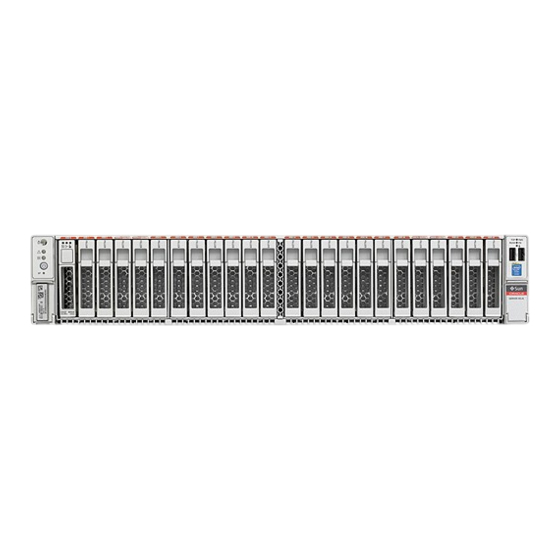
Storage drives 0 through 11 (HDD/SSD; Storage drives 3 and 4: HDD/SSD/NVMe) Storage drives 12 through 23 (HDD/SSD; Storage drives 19 and 20: HDD/SSD/NVMe) Top Fan Fault LED: amber; Power Supply (PS) Fault LED: amber; System Over Temperature Warning LED: amber About the Oracle Server X5-2L... -
Page 18: Rear Panel Components And Cable Connections
PCIe slot 1 (Nonfunctional in single-processor systems.) PCIe slot 2 (Nonfunctional in single-processor systems.) PCIe slot 3 (Nonfunctional in single-processor systems. This slot is the default slot for the optional Oracle PCIe Switch Controller Card.) Network (NET) 100/1000/10000 ports (NET3–NET0) (NET2 and NET3 are nonfunctional in single-processor systems.) -
Page 19: About System Components
DB-15 video connector PCIe slot 4 PCIe slot 5 PCIe slot 6 (This slot is the default slot for the Oracle Storage 12 Gb/s SAS PCIe RAID HBA.) For more information on rear panel components and connections, refer to “Rear Panel Note - Connector Locations”... - Page 20 Twelve 3.5-inch storage drives Twenty-four 2.5-inch storage drives Eight 2.5-inch storage drives Front disk backplane for twelve 3.5-inch drives Front disk backplane for twenty-four 2.5-inch drives Front disk backplane for eight 2.5-inch drives Oracle Server X5-2L Service Manual • May 2015...
-
Page 21: Customer-Replaceable Units
P0 DIMM sockets.) Air baffle Top cover Oracle Storage 12 Gb/s SAS PCIe RAID HBA and super capacitor PCIe cards (PCIe slots 1, 2, and 3 are nonfunctional in single-processor systems.) I/O and internal USB card Internal USB drive... -
Page 22: Field-Replaceable Units
“Servicing NVMe Cables (FRU)” on page 174 card and the disk backplane. Oracle Storage 12 Located in PCIe slot 6, the Oracle Storage 12 Gb/s SAS “Servicing the Oracle Storage 12 Gb/s SAS PCIe RAID Gb/s SAS PCIe PCIe RAID HBA manages SAS storage drives. - Page 23 About System Components Related Information “Customer-Replaceable Units” on page 21 ■ “Illustrated Parts Breakdown” on page 19 ■ “Servicing FRUs” ■ About the Oracle Server X5-2L...
- Page 24 Oracle Server X5-2L Service Manual • May 2015...
-
Page 25: Troubleshooting And Diagnostics
Troubleshooting and Diagnostics This section includes information about troubleshooting hardware component faults for the Oracle Server X5-2L. It contains the following topics. Description Link Maintenance-related information and procedures that you “Troubleshooting Server Component Hardware can use to troubleshoot and repair server hardware issues. -
Page 26: Troubleshooting Server Hardware Faults
3. Prepare the server for service using Oracle ILOM. If you have determined that the hardware fault requires service (physical access to the server), use Oracle ILOM to take the server offline, activate the Locate LED, and power off the server. - Page 27 This procedure uses the basic troubleshooting steps described in “Basic Troubleshooting Process” on page Use this procedure to troubleshoot hardware faults with the Oracle ILOM web interface and, if necessary, prepare the server for service. This procedure provides one basic approach to troubleshooting hardware faults. It Note - uses a combination of the Oracle ILOM web interface and command-line interface (CLI).
- Page 28 Troubleshoot Hardware Faults Using the Oracle ILOM Web Interface In the Status section of the Summary Information screen, identify the server subsystem that requires service. In the above example, the Status screen shows that the Processor subsystem requires service. This indicates that a hardware component within the subsystem is in a fault state.
-
Page 29: Troubleshooting And Diagnostic Information
To prepare the server for service, see “Preparing for Service”. After servicing the component, you might need to clear the fault in Oracle ILOM. For more information, refer the service procedure for the component. Service the component. Troubleshooting and Diagnostic Information The following table lists diagnostic and troubleshooting-related procedures and references that can assist you with resolving server issues. -
Page 30: Troubleshooting Using The Server Front And Rear Panel Status Indicators
2. After a few minutes, the main Power/OK LED slowly flashes the standby blink pattern (0.1 seconds on, 2.9 seconds off), indicating that the SP (and Oracle ILOM) is ready for use. In standby power mode, the server is not initialized or fully powered on at this point. - Page 31 ■ OFF – Server is operating normally. ■ FAST BLINK – Use Oracle ILOM to activate this LED indicator to enable you to locate a particular system quickly and easily. ■ Pressing the Locate button will toggle the LED indicator fast blink on or off.
-
Page 32: Server Fan Status Indicators
Troubleshoot Hardware Faults Using the Oracle ILOM Web Interface Icon Color State and Meaning Status Indicator Name Rear Power Rear Amber Indicates that one of the server power supplies has failed. Supply Fault ■ OFF – Indicates steady state; no service is required. -
Page 33: Power Supply Status Indicators
Troubleshoot Hardware Faults Using the Oracle ILOM Web Interface Status Icon Color State and Meaning Indicator Name OK to Remove Blue ■ STEADY ON – The storage drive can be removed safely during a hot-plug operation. ■ OFF – The storage drive has not been prepared for removal. -
Page 34: Ethernet Ports Status Indicators
DIMM Fault Status Indicators: Each of the 24 DIMM sockets on the motherboard has ■ an amber fault status indicator (LED) associated with it. If Oracle ILOM determines that a DIMM is faulty, pressing the Fault Remind button on the motherboard I/O card signals the service processor to light the fault LED associated with the failed DIMM. -
Page 35: Troubleshooting System Cooling Issues
Troubleshoot Hardware Faults Using the Oracle ILOM Web Interface least one of the power supplies. This LED is provided to help prevent service actions on the server internal components while the AC power cords are installed and power is being supplied to the server. - Page 36 Troubleshoot Hardware Faults Using the Oracle ILOM Web Interface airflow through the server is disrupted and the cooling system fails to function properly causing the server internal temperature to rise. Action: Inspect the server front and back panel vents for blockage from dust or debris.
-
Page 37: Troubleshooting Power Issues
The power supplies are designed to operate at a particular voltage and within an acceptable range of voltage fluctuations (refer to “Electrical Power Requirements” in “Oracle Server X5-2L Installation Guide ”). -
Page 38: Top Cover
Troubleshoot Hardware Faults Using the Oracle ILOM Web Interface Action: Check that the AC cables are connected to both power supplies. Check that the power supplies are operational (the PSU indicator panel should have a lit green AC OK indicator). -
Page 39: Managing Server Hardware Faults Through The Oracle Ilom Fault Management Shell
For more information about how to use the Oracle ILOM Fault Management Shell, see the Oracle ILOM User's Guide for System Monitoring and Diagnostics Firmware Release 3.2.x in the Oracle Integrated Lights Out Manager (ILOM) 3.2 Documentation Library at... -
Page 40: Diagnostic Tools
Diagnostic Tools The selection of diagnostic tools available for your server range in complexity from a comprehensive validation test suite (Oracle VTS) to a chronological event log (Oracle ILOM System Log). The selection of diagnostic tools also includes standalone software packages, firmware-based tests, and hardware-based LED indicators. -
Page 41: Diagnostic Tool Documentation
Attaching Devices to the Server Diagnostic Tool Type What It Does Accessibility Remote Capability such as the Oracle Server X5- (CLI) to run UEFI diagnostics. Oracle Solaris Operating Displays various kinds of Requires operating Local, and over commands system system information. -
Page 42: Attach Devices To The Server
Connect an Ethernet cable to the Gigabit Ethernet (NET) connectors as needed for OS support. “Rear Panel Connector Locations” on page To connect to the service processor's Oracle ILOM over the network, connect an Ethernet cable to the Ethernet port labeled NET MGT. “Rear Panel Connector Locations” on page... - Page 43 60 seconds if the server is not connected to a terminal, PC, or workstation. Note - Oracle ILOM will signal a fault on any installed power supply that is not connected to an AC power source, since it might indicate a loss of redundancy.
-
Page 44: Configuring Serial Port Sharing
By default, the SP console (SER MGT) port sends serial port output from the server. Using Oracle ILOM, you can specify that the host console (COM1) be assigned as owner of the server serial port output. This feature is useful for Windows kernel debugging, as it enables you to view non-ASCII character traffic from the host console. -
Page 45: Server Operating System Names For The Nvme Storage Drives
To log in, open a web browser and direct it using the IP address of the server SP. Log in as root or a user with administrator privileges. See “Accessing Oracle ILOM” in the Oracle X5 Series Servers Administration Guide. -
Page 46: Ethernet Port Boot Order And Device Naming
0 eth 0 Ethernet NET 1 3A01 ixgbe 1 eth 1 Ethernet 2 NET 2 8200 ixgbe 2 eth 2 Ethernet 3 NET 3 8201 ixgbe 3 eth 3 Ethernet 4 Oracle Server X5-2L Service Manual • May 2015... -
Page 47: Rear Panel Pinhole Switches
Assign Serial Port Output Using the Web Interface For Windows, port names like Ethernet, Ethernet 2, Ethernet 3, and Ethernet 4 are used Note - by default. However, actual port naming is based on the order of enumeration, typically during operating system installation. -
Page 48: Getting Help
Superuser password Summary of the problem and the work being done when the problem occurred Other Useful Information IP address Server name (system host name) Network or internet domain name Proxy server configuration Oracle Server X5-2L Service Manual • May 2015... -
Page 49: Related Information
From the command-line interface (CLI), type the command: show/SYS. ■ From the web interface, view the serial number on the System Information screen. ■ Using Oracle System Assistant, view the serial number on the System Overview screen. ■ Troubleshooting and Diagnostics... - Page 50 Oracle Server X5-2L Service Manual • May 2015...
-
Page 51: Preparing For Service
Follow all standard cautions, warnings, and instructions marked on the equipment and ■ described in the Oracle Server X5-2L Safety and Compliance Guide and Important Safety Information for Oracle's Hardware Systems. Ensure that the voltage and frequency of your power source match the voltage and ■... -
Page 52: Safety Symbols
Wear an antistatic wrist strap and use an antistatic mat when handling components such as drive assemblies, boards, or cards. When servicing or removing server components, attach an antistatic strap to your wrist and then to a metal area on the chassis. Then disconnect Oracle Server X5-2L Service Manual • May 2015... -
Page 53: Fru Key Identity Properties (Kip) Automated Update
■ When a server FRU that contains the KIP is removed and a replacement component is installed, the KIP of the replacement component is programmed by Oracle ILOM to contain the same KIP as the other two components. Preparing for Service... -
Page 54: Related Information
“Powering Down the Server” on page 55 ■ “Disconnect Cables From the Server” on page 60 ■ “Extend the Server to the Maintenance Position” on page 61 ■ “Remove the Server From the Rack” on page 63 ■ Oracle Server X5-2L Service Manual • May 2015... -
Page 55: Powering Down The Server
Power Down the Server Gracefully Using the Oracle ILOM CLI “Take Antistatic Measures” on page 64 ■ “Remove the Server Top Cover” on page 64 ■ “Remove the Fan Assembly Door From the Server” on page 65 ■ “Remove the Disk Cage Cover From the Server” on page 67 ■... - Page 56 At the Oracle ILOM prompt, shut down the operating system: stop /System -> If the system is running the Oracle Solaris OS, refer to the Oracle Solaris system administration documentation for additional information. Disconnect the power and cables from the server.
- Page 57 Disconnect the power cords and data cables from the server. “Disconnect Cables From the Server” on page When you power down the server using Oracle ILOM, the server enters standby Caution - power mode. Power is still directed to the service processor remote management subsystem and power supply fans.
-
Page 58: Power Button
“Server System-Level Status Indicators” on page 31 ■ “Power Down the Server Gracefully Using the Oracle ILOM CLI” on page 55 ■ “Power Down the Server Gracefully Using the Oracle ILOM Web Interface” on page 56 ■ “Power On the Server” on page 233 ■... - Page 59 Log in to the Oracle ILOM command-line interface (CLI) using an Administrator account. Oracle ILOM displays the default command prompt (->), indicating that you have successfully logged in to Oracle ILOM. From the CLI prompt, type the following command: ->...
-
Page 60: Disconnect Cables From The Server
Related Information “Power Down the Server for Immediate Shutdown Using the Power Button” on page 58 ■ “Power Down the Server for Immediate Shutdown Using the Oracle CLI” on page 59 ■ “Power On the Server” on page 233 ■... -
Page 61: Extend The Server To The Maintenance Position
To prevent the rack from tipping forward when the server is extended, extend all rack anti-tilt devices. For instructions for stabilizing the rack, refer to “Stabilize the Rack for Installation” in “Oracle Server X5-2L Installation Guide ”. Verify that no cables will be damaged or will interfere when the server is extended. - Page 62 The server is now in the extended maintenance position. Related Information “Disconnect Cables From the Server” on page 60 ■ “Remove the Server From the Rack” on page 63 ■ “Reinstall the Server in the Rack” on page 230 ■ Oracle Server X5-2L Service Manual • May 2015...
-
Page 63: Remove The Server From The Rack
Remove the cable management arm (CMA). For instructions for removing the CMA, see the “Remove the Cable Management Arm” in “Oracle Server X5-2L Installation Guide ”. Extend the server to the maintenance position. “Extend the Server to the Maintenance Position” on page... -
Page 64: Take Antistatic Measures
Servicing some components requires that the top cover be removed. Note - Ensure that AC power cords are disconnected from the server power supplies. Unlatch the top cover [1]. Press the green release button on the top of the server cover. Oracle Server X5-2L Service Manual • May 2015... -
Page 65: Remove The Fan Assembly Door From The Server
Remove the Fan Assembly Door From the Server Removing the Server Top Cover FIGURE 9 While pressing the top cover release button, slide the cover toward the rear of the server [2]. If necessary, open the fan assembly door. Lift up and remove the top cover [2]. - Page 66 “Take Antistatic Measures” on page 64 ■ “Remove the Server Top Cover” on page 64 ■ “Install the Server Top Cover” on page 226 ■ “Install the Fan Assembly Door” on page 228 ■ Oracle Server X5-2L Service Manual • May 2015...
-
Page 67: Remove The Disk Cage Cover From The Server
Remove the Disk Cage Cover From the Server Remove the Disk Cage Cover From the Server Before you service the server's storage drive backplane, you should first remove the server's disk cage cover. This procedure is only required for systems configured with eight 2.5-inch storage Note - drives. - Page 68 Slide the cover forward and lift to remove the disk cage cover from the chassis [2]. Related Information “Take Antistatic Measures” on page 64 ■ “Remove the Server Top Cover” on page 64 ■ “Install the Server Top Cover” on page 226 ■ Oracle Server X5-2L Service Manual • May 2015...
- Page 69 Remove the Disk Cage Cover From the Server “Install the Disk Cage Cover” on page 229 ■ Preparing for Service...
- Page 70 Oracle Server X5-2L Service Manual • May 2015...
-
Page 71: Servicing Crus That Do Not Require Server Power-Off
“Removing and Replacing an HDD or SSD Storage Drive” on page 73 ■ “Removing and Replacing an NVMe Storage Drive Using Oracle Solaris” on page 79 ■ “Removing and Replacing an NVMe Storage Drive Using Oracle Linux” on page 82 ■... -
Page 72: Storage Drives Hot-Plug Conditions
“Removing and Replacing an HDD or SSD Storage Drive” on page 73 ■ “Removing and Replacing an NVMe Storage Drive Using Oracle Solaris” on page 79 ■ “Removing and Replacing an NVMe Storage Drive Using Oracle Linux” on page 82 ■... -
Page 73: Removing And Replacing An Hdd Or Ssd Storage Drive
Remove an HDD or SSD Storage Drive Removing and Replacing an HDD or SSD Storage Drive The following sections describe how to remove and replace an HDD or SSD storage drive. “Remove an HDD or SSD Storage Drive” on page 73 ■... - Page 74 Storage drive 5 (HDD/SSD) Storage drive 9 (HDD/SSD) Storage drive 2 (HDD/SSD) Storage drive 6 (HDD/SSD) Storage drive 10 (HDD/SSD) Storage drive 3 (HDD/SSD) Storage drive 7 (HDD/SSD) Storage drive 11 (HDD/SSD) Oracle Server X5-2L Service Manual • May 2015...
- Page 75 Remove an HDD or SSD Storage Drive Drive Location and Numbering on a Server With Twenty-Four 2.5-Inch Drives FIGURE 14 Figure Legend Storage drives 0 through 11 (HDD/SSD; Storage drives 3 and 4: HDD/SSD/NVMe) Storage drives 12 through 23 (HDD/SSD; Storage drives 19 and 20: HDD/SSD/NVMe) If you are removing an HDD or SSD storage drive, type the required operating system commands to stop the server from using the drive;...
- Page 76 The latch is not an ejector. Do not open the latch too far to the right. Doing so can Caution - damage the latch. Grasp the latch and pull the drive out of the drive slot. Oracle Server X5-2L Service Manual • May 2015...
- Page 77 Remove an HDD or SSD Storage Drive Removing a Storage Drive FIGURE 16 Consider your next steps: If you are replacing the drive, continue to “Install an HDD or SSD Storage ■ Drive” on page If you are not replacing the drive, install a filler panel in the empty drive slot to maintain ■...
- Page 78 The procedures that you perform at this point depend on how your data is configured. You might need to partition the drive, create file systems, load data from backups, or have the drive updated from a RAID configuration. Oracle Server X5-2L Service Manual • May 2015...
-
Page 79: Removing And Replacing An Nvme Storage Drive Using Oracle Solaris
■ Removing and Replacing an NVMe Storage Drive Using Oracle Solaris NVMe storage drives are supported only on servers that are running Oracle Solaris or Note - Oracle Linux operating systems. Servers that are running Oracle VM, Windows Server, Red Hat Enterprise Linux, SUSE Linux Enterprise Server, or VMware ESXi do not support NVMe drives. - Page 80 226. Verify Removal of an NVMe Storage Drive To verify that the NVMe drive has been removed, type: hotplug list –lc The following output appears for the NVMe drive that you removed: Oracle Server X5-2L Service Manual • May 2015...
- Page 81 Install an NVMe Storage Drive in the Server # hotplug list –lc Connection State Description Path ------------------------------------------------------------------ pcie13 EMPTY PCIe-Native /pci@7a,0/pci8086,2f08@3/pci111d,80b5@4 Install an NVMe Storage Drive in the Server Perform this procedure to physically install an NVMe storage drive into the server. Note - After you physically remove an NVMe storage drive from the server, wait at least 10 seconds before installing a replacement drive.
-
Page 82: Removing And Replacing An Nvme Storage Drive Using Oracle Linux
■ Removing and Replacing an NVMe Storage Drive Using Oracle Linux NVMe storage drives are supported only on servers that are running Oracle Solaris or Note - Oracle Linux operating systems. Servers that are running Oracle VM, Windows Server, Red Hat Enterprise Linux, SUSE Linux Enterprise Server, or VMware ESXi do not support NVMe drives. - Page 83 Unmount an NVMe Storage Drive b. To obtain the slot number (APIC ID) for the bus address, type the following command to list all of the PCIe slot numbers and the corresponding bus addresses: egrep –H ‘.*’ /sys/bus/pci/slots/*/address This commands returns output similar to the following: /sys/bus/pci/slots/10/address:0000:b8:00 /sys/bus/pci/slots/11/address:0000:b6:00 /sys/bus/pci/slots/12/address:0000:b2:00 (instance nvme0, pcie slot 12, drive label...
- Page 84 -nnd :0953 View the command output and verify that the entry for the slot number that was disabled no longer appears. This commands returns output similar to the following: Oracle Server X5-2L Service Manual • May 2015...
- Page 85 Install an NVMe Storage Drive in the Server b2:00.0 Non-Volatile memory controller [0108]: Intel Corporation Device [8086:0953] (rev 01) b6:00.0 Non-Volatile memory controller [0108]: Intel Corporation Device [8086:0953] (rev 01) b8:00.0 Non-Volatile memory controller [0108]: Intel Corporation Device [8086:0953] (rev 01) Install an NVMe Storage Drive in the Server Perform this procedure to physically install an NVMe storage drive into the server.
-
Page 86: Removing And Replacing A Rear Storage Drive
Remove the rear storage drive. a. On the storage drive that you want to remove, push the drive release button to open the latch [1]. Oracle Server X5-2L Service Manual • May 2015... - Page 87 Remove a Rear Storage Drive b. Grasp the drive latch, and pull the drive out of the drive slot [2]. The drive latch is not an ejector. Do not open the latch too far to the right. Doing so Caution - can damage the latch.
- Page 88 Slide the drive into the drive slot until it is fully seated. Installing a Rear-Mounted Storage Drive FIGURE 19 Close the drive latch to lock the drive in place. Perform administrative procedures to reconfigure the drive. Oracle Server X5-2L Service Manual • May 2015...
-
Page 89: Servicing Fan Modules (Cru)
Servicing Fan Modules (CRU) The procedures that you perform at this point depend on how your data is configured. You might need to partition the drive, create file systems, load data from backups, or have the drive updated from a RAID configuration. Related Information “Rear Panel Components and Cable Connections”... - Page 90 Amber – The fan module is faulty. The front Top Fan LED and the front and rear panel Service Required LEDs are also lit if the system detects a fan module fault. Use a No. 2 Phillips screwdriver to loosen the captive screw that secures the faulty fan module in the chassis [1]. Oracle Server X5-2L Service Manual • May 2015...
- Page 91 Remove a Fan Module Removing a Fan Module FIGURE 21 Grasp both the captive screw and the opposite end of the module and lift the fan module straight up and out of the chassis, and set it aside on an antistatic mat [2].
-
Page 92: Install A Fan Module
With the top cover fan assembly door open, install the replacement fan module into the server [1]. The fan modules are keyed to ensure that they are installed in the correct orientation. Installing a Fan Module FIGURE 22 Oracle Server X5-2L Service Manual • May 2015... -
Page 93: Servicing Power Supplies (Cru)
Servicing Power Supplies (CRU) Press down on the fan module and apply firm pressure to fully seat the fan module. Verify that the fan module status indicator (LED) on the replacement fan module is not illuminated. Using your thumb and forefinger, tighten the captive screw to secure the fan module to the chassis. -
Page 94: Remove A Power Supply
“Powering Down the Server” on page 55 ■ Remove a Power Supply Prepare the system for power supply removal. Refer to “Take Antistatic Measures” on page Identify which power supply requires replacement. Oracle Server X5-2L Service Manual • May 2015... - Page 95 (->) to identify a power supply failure. Alternatively, to list all known faults in the server, log into the Oracle Solaris OS and issue the fmadm faulty command, or log into the Oracle ILOM service processor from the Oracle ILOM Fault Management Shell and issue the fmadm faulty command.
- Page 96 CMA out of the way. For instructions for disconnecting the CMA left-side connectors, refer to “Remove the Cable Management Arm” in “Oracle Server X5-2L Installation Guide ”. When disconnecting the CMA left-side connectors, be sure to use your arm to...
-
Page 97: Install A Power Supply
Install a Power Supply Related Information “Rear Panel Components and Cable Connections” on page 18 ■ “Power Supply Status Indicators” on page 33 ■ “Install a Power Supply” on page 97 ■ Install a Power Supply Always replace the failed power supply with the same type model of power supply. Caution - Remove the replacement power supply from its packaging, and place it on an antistatic mat. - Page 98 Verify that the amber Service Required LED on the replaced power supply and the Service Required LEDs are not lit on the front and rear panels. After you have replaced Power Supply 0, you might need to reset the Oracle ILOM Note - service processor (SP) to propagate the key identity properties (KIP) data to the new power supply.
- Page 99 Install a Power Supply Related Information “Rear Panel Components and Cable Connections” on page 18 ■ “Power Supply Status Indicators” on page 33 ■ “Remove a Power Supply” on page 94 ■ Servicing CRUs That Do Not Require Server Power-Off...
- Page 100 Oracle Server X5-2L Service Manual • May 2015...
-
Page 101: Servicing Crus That Require Server Power-Off
“Servicing FRUs” ■ Servicing the DIMMs (CRU) The Oracle Server X5-2L supports a variety of DDR4 DIMM configurations that can include quad-rank (QR), dual-rank (DR), and single-rank (SR) DDR4 DIMMs. These procedures require that you handle components that are sensitive to Caution - electrostatic discharge. -
Page 102: Dimm And Processor Physical Layout
0 (P0) is on the left. Notice that each processor, P0 and P1, have four memory channels that are labeled, from left to right, Ch C, Ch D, Ch B, and Ch A. Oracle Server X5-2L Service Manual • May 2015... -
Page 103: Dimm Population Scenarios
Servicing the DIMMs (CRU) DIMM and Processor Physical Layout FIGURE 26 In single-processor systems, the DIMM sockets associated with processor 1 (P1) are Note - nonfunctional and should not be populated with DIMMs. Related Information “DIMM Population Scenarios” on page 103 ■... -
Page 104: Dimm Population Rules
Symmetry is achieved by adhering to the following guidelines: In single-processor systems, populate DIMMs of the same size in multiples of four. ■ In dual-processor systems, populate DIMMs of the same size in multiples of eight. ■ Oracle Server X5-2L Service Manual • May 2015... -
Page 105: Populating Dimms In Single-Processor Systems For Optimal System Performance
Servicing the DIMMs (CRU) Populate the DIMM sockets in the order described in the following sections. ■ The following sections provide an example of how to populate the DIMM sockets to achieve optimal system performance. Not all possible configurations are shown here. Note - “Populating DIMMs in Single-Processor Systems for Optimal System ■... -
Page 106: Populating Dimms In Dual-Processor Systems For Optimal System Performance
DIMM sockets is Ch C first, Ch A second, Ch D third, and Ch B last. Repeat the same population sequence for the black sockets with white tabs, and finally, for the white sockets. Oracle Server X5-2L Service Manual • May 2015... - Page 107 Servicing the DIMMs (CRU) DIMM Population Order for Dual-Processor Systems FIGURE 28 The following table describes the proper order in which to install DIMMs in a dual-processor system using the numbered callouts in the above figure, the memory channel labels (Ch A through Ch D), and the DIMM socket labels (D0 through D11).
-
Page 108: Dimm Operating Speeds
Inconsistencies Between DIMM Fault Indicators and the BIOS Isolation of Faulty DIMMs When a single DIMM is marked as failed by Oracle ILOM (for example, fault.memory. intel.dimm.training-failed is listed in the service processor Event Log), BIOS might disable the entire memory channel that contains the failed DIMM, up to three DIMMs. As a result, none of the memory installed in the disabled channel will be available to the operating system. -
Page 109: Identify And Remove A Faulty Dimm
Identify and Remove a Faulty DIMM you press the Fault Remind button, it is likely that the capacitor powering the fault remind circuit has lost its charge. This can happen if the Fault Remind button is pressed for several minutes with fault LEDs lit or if power has been removed from the server for more than 15 minutes. - Page 110 If the DIMM fault LED is off, then the DIMM is operating properly. ■ If the DIMM fault LED is on (amber), then the DIMM is faulty and should be replaced [1]. ■ Oracle Server X5-2L Service Manual • May 2015...
- Page 111 Identify and Remove a Faulty DIMM Identifying a Faulty DIMM FIGURE 30 To remove the faulty DIMM, do the following: Rotate both DIMM socket ejectors outward as far as they will go. a. The DIMM is partially ejected from the socket. See Figure Figure b. ...
- Page 112 “DIMM Population Rules” on page 104 ■ “Populating DIMMs for Optimal System Performance” on page 104 ■ “DIMM Rank Classification Labels” on page 108 ■ “Install a DIMM” on page 113 ■ Oracle Server X5-2L Service Manual • May 2015...
-
Page 113: Install A Dimm
Install a DIMM Install a DIMM Unpack the replacement DDR4 DIMM and place it on an antistatic mat. Ensure that the replacement DDR4 DIMM matches the size of the DIMM it is replacing. You must not replace a single-rank or dual-rank DIMM with a quad-rank DIMM and vice versa. If you violate this rule, the performance of the server might be adversely affected. - Page 114 226. c. Return the server to the normal rack position. “Return the Server to the Normal Rack Position” on page 231. d. Reconnect the power cords and data cables to the server. Oracle Server X5-2L Service Manual • May 2015...
-
Page 115: Servicing Pcie Cards (Cru)
The procedures in this section should not be used to service the Oracle Storage 12 Caution - Gb/s SAS PCIe RAID HBA card that is located in PCIe slot 6 or the optional Oracle PCIe NVMe switch card that is located in PCIe slot 3. The Oracle Storage 12 Gb/s SAS PCIe RAID HBA card and Oracle PCIe NVMe switch card are field replaceable units (FRUs) and should be serviced only by qualified Oracle Service personnel. -
Page 116: Pcie Slot Locations
PCIe slot 1 (PCIe slot 1 is nonfunctional in single-processor systems.) PCIe slot 2 (PCIe slot 2 is nonfunctional in single-processor systems.) PCIe slot 3 (PCIe slot 3 is nonfunctional in single-processor systems. Primary slot for the optional Oracle PCIe NVMe switch card) PCIe slot 4 Oracle Server X5-2L Service Manual •... -
Page 117: Remove A Pcie Card
Remove a PCIe Card PCIe slot 5 PCIe slot 6 (Primary slot for the Oracle Storage 12 Gb/s SAS PCIe RAID HBA card) All of the PCIe slots comply with the PCI Express 3.0 specification and can Note - accommodate 25 Watt PCIe3 cards. - Page 118 Note the cable connections in order to ease proper reconnection of the cables. Rotate the PCIe card locking mechanism [1], and then lift up on the PCIe card to disengage it from the motherboard connectors [2]. FIGURE 34 Removing the PCIe Card Oracle Server X5-2L Service Manual • May 2015...
-
Page 119: Install A Pcie Card
Unpack the replacement PCIe card, and place it on an antistatic mat. Locate the proper PCIe slot for the card you are replacing. PCIe slot 3 is the primary slot for the Oracle PCIe NVMe switch card. This card is Note - required for controlling and managing the optional NVMe storage drives. - Page 120 Reconnect the cables to the PCIe card that you unplugged during the removal procedure [2]. Return the server to operation. a. Lower the air baffle to the installed position. Install the top cover. b. Oracle Server X5-2L Service Manual • May 2015...
-
Page 121: Servicing The Internal Usb Flash Drives (Cru)
Use Oracle ILOM to clear any server PCIe card faults. If a PCIe card fault message in Oracle ILOM is not cleared under Open Problems, you must manually clear the fault in Oracle ILOM. For instructions for manually clearing a PCIe card fault, see the procedure "Clear Faults for Undetected Replaced or Repaired... -
Page 122: Servicing The Oracle System Assistant Usb Flash Drive
Servicing the Oracle System Assistant USB Flash Drive If the Oracle System Assistant software is corrupted on the USB flash drive, you should try to repair it before replacing the USB flash drive. Oracle System Assistant uses a specially formated USB flash drive. Do not replace the Oracle System Assistant flash drive with a standard flash drive. - Page 123 “Remove the Server Top Cover” on page To remove a USB flash drive, grasp the flash drive and pull it from the slot. If your server is configued with Oracle System Assistant software, it is located on the Note - USB flash drive in the bottom USB slot.
-
Page 124: Install An Internal Usb Flash Drive
Install an Internal USB Flash Drive Unpack the replacement USB flash drive. Insert the flash drive into the USB slot. If you are replacing the Oracle System Assistant USB flash drive, insert the USB flash Note - drive into the bottom USB slot. - Page 125 Install an Internal USB Flash Drive Installing a USB Flash Drive FIGURE 37 Return the server to operation. Install the server top cover. a. “Install the Server Top Cover” on page 226. b. Return the server to the normal rack position. “Return the Server to the Normal Rack Position”...
-
Page 126: Servicing The Battery (Cru)
Servicing the Battery (CRU) If the USB flash drive that you replaced was the Oracle System Assistant USB flash drive, you need to reinstall Oracle System Assistant on the new USB flash drive. For instructions, see the procedures for restoring Oracle System Assistant in the Oracle X5 Series Servers Administration Guide at http://www.oracle.com/goto/x86AdminDiag/docs. - Page 127 Remove the Battery “Electrostatic Discharge Safety” on page d. Remove the server top cover. “Remove the Server Top Cover” on page Swivel the air baffle into the upright position to allow access to the battery. e. To dislodge the battery from its retainer, gently push the top edge of the battery away from the retainer.
-
Page 128: Install The Battery
If the service processor is configured to synchronize with a network time server using Note - the Network Time Protocol (NTP), the Oracle ILOM SP clock will be reset as soon as the server is powered on and connected to the network; otherwise, proceed to the next step. -
Page 129: Servicing Frus
(FRU)” on page 209 Related Information “Servicing CRUs That Do Not Require Server Power-Off” ■ “Servicing CRUs That Require Server Power-Off” ■ Servicing Processors (FRU) Processors should be removed and replaced only by authorized Oracle Service Caution - personnel. Servicing FRUs... -
Page 130: Selecting The Correct Processor Removal And Replacement Tool
The processors supported by the Oracle Server X5-2L are available in two sizes. The processors with 10 or fewer cores are smaller than the processors with 12 or more cores. You can... - Page 131 Servicing Processors (FRU) For instructions, refer to the Oracle Integrated Lights Out Manager (ILOM) 3.2 Documentation Library at http://www.oracle.com/goto/ILOM/docs. Visually check the size of the processor installed in the server. ■ This requires that you remove the processor heatsink and open the processor independent loading mechanism (ILM) assembly that holds the processor in the socket.
- Page 132 The tool for the smaller processors (processors with 10 or fewer cores) is color-coded green. The tool for the larger processors (processors with 12 or more cores) is color-coded pink. See Figure Oracle Server X5-2L Service Manual • May 2015...
- Page 133 Servicing Processors (FRU) Color-Coded Processor Removal and Replacement Tool FIGURE 41 Figure Legend Green, color-coded removal and replacement tool for the smaller processor models E5-2630 V3 (8-core) and E5- 2660 V3 (10-core) Pink, color-coded removal and replacement tool for the larger processor models E5-2690 V3 (12-core) and E5- 2699 V3 (18-core) The pink color-coded processor removal and replacement tool must be used only Caution -...
-
Page 134: Remove A Processor
This can happen if the Fault Remind button is pressed for a long time with fault LEDs lit or if power has been removed from the server for more than 15 minutes. Oracle Server X5-2L Service Manual • May 2015... - Page 135 Remove a Processor The processor fault LED for the faulty processor lights. The processor fault LEDs are located next to the processors: If the processor fault LED is off, then the processor is operating properly. ■ If the processor fault LED is on (amber), then the processor is faulty and should be replaced. ■...
- Page 136 To separate the heatsink from the top of the processor, gently twist the heatsink left and right, while pulling upward, and then lift off the heatsink and place it upside down on a flat surface. Oracle Server X5-2L Service Manual • May 2015...
- Page 137 Remove a Processor A thin layer of thermal grease separates the heatsink and the processor. This grease acts as an adhesive. Do not allow the thermal grease to contaminate the work space or other components. Note - Use an alcohol pad to clean the thermal grease from the underside of the heatsink.
- Page 138 For information on how to select the correct processor removal and replacement tool, see “Selecting the Correct Processor Removal and Replacement Tool” on page 130. Oracle Server X5-2L Service Manual • May 2015...
- Page 139 Remove a Processor Removing a Processor FIGURE 44 Related Information “Install a Processor” on page 140 ■ Servicing FRUs...
-
Page 140: Install A Processor
(circuit side up) in the tool so that the triangle on the corner of the processor aligns with the triangle on the side of the processor removal and replacement tool [2]. Oracle Server X5-2L Service Manual • May 2015... - Page 141 Install a Processor c. Lower the processor into the tool and press the tool release lever to release the center button and engage the processor [3]. An audible click indicates that the processor is locked into place. d. Properly position the tool over the processor socket and lower it into place [4].
- Page 142 Install a Processor Installing a Processor FIGURE 45 Visually check the alignment of the processor in the socket [1]. When properly aligned, the processor sits flat in the processor socket. Oracle Server X5-2L Service Manual • May 2015...
- Page 143 Install a Processor Do not press down on the processor. Irreparable damage to the processor or Caution - motherboard might occur from excessive downward pressure. Do not forcibly seat the processor into the socket. Excessive downward pressure might damage the socket pins. Swing the processor ILM assembly load plate into the closed position [2].
- Page 144 Return the server to the normal rack position. “Return the Server to the Normal Rack Position” on page 231. Reconnect the power cords to the power supplies, and power on the server. d. Oracle Server X5-2L Service Manual • May 2015...
- Page 145 To show server faults, log in to the server as root using the Oracle ILOM CLI, and type the following command to list all known faults on the server: -> show /SP/faultmgmt...
-
Page 146: Servicing The Front And Rear Storage Drive Backplanes (Fru)
“Servicing Storage Drives and Rear Drives (CRU)” on page 71 ■ “Servicing SAS Cables (FRU)” on page 167 ■ “Servicing NVMe Cables (FRU)” on page 174 ■ Remove the Storage Drive Backplane for Eight- Drive Systems Prepare the server for service. Oracle Server X5-2L Service Manual • May 2015... - Page 147 Disconnect the cables from the storage drive backplane. Disconnect the two SAS cables from the storage drive backplane to the a. Oracle Storage 12 Gb/s SAS PCIe RAID HBA [1]. Note the cable connections in order to ease proper reconnection of the cables. Servicing FRUs...
- Page 148 Removing the Storage Drive Backplane for Eight-Drive Systems FIGURE 47 b. Disconnect the power cable from the storage drive backplane [2]. c. If present, disconnect the two optional NVMe cables from the storage drive backplane [2]. Oracle Server X5-2L Service Manual • May 2015...
-
Page 149: Install The Storage Drive Backplane For Eight-Drive Systems
Install the Storage Drive Backplane for Eight-Drive Systems d. If the server has a DVD drive, disconnect the power and DVD data connections from the storage drive backplane [3]. “Remove the DVD Drive” on page 188. e. Disconnect the auxiliary signal cable from the storage drive backplane [4] Using a No. - Page 150 [3]. Reconnect the cables to the storage drive backplane. Reconnect the auxiliary signal cable to the storage drive backplane [3]. a. Oracle Server X5-2L Service Manual • May 2015...
- Page 151 “Install NVMe Cables” on page 177. e. Reconnect the two SAS cables to the storage drive backplane from the Oracle Storage 12 Gb/s SAS PCIe RAID HBA [6]. To ensure proper SAS cable connections, see “Install SAS Storage Drive Cables” on page 171.
-
Page 152: Remove The Storage Drive Backplane For Twelve-Drive Systems
IMPORTANT: When the disk backplane is replaced, the key identity properties (KIP) Note - of the disk backplane is programmed by Oracle ILOM to contain the same KIP as the other quorum member components. If you have removed other quorum member components, you might need to manually program the product serial number (PSN) into the new disk backplane. - Page 153 SAS cables from the storage drive backplane to the Oracle Storage 12 Gb/s SAS PCIe RAID HBA [1]. Note the cable connections in order to ease proper reconnection of the cables. Servicing FRUs...
- Page 154 Disconnect the power cable from the storage drive backplane [3]. Using a No. 2 Phillips screwdriver, loosen the right-side spring-mounted screw that secures the storage drive backplane to the chassis [4]. Oracle Server X5-2L Service Manual • May 2015...
-
Page 155: Install The Storage Drive Backplane For Twelve-Drive Systems
Install the Storage Drive Backplane for Twelve-Drive Systems Lift the storage drive backplane up to release it from the standoff hooks and out of the chassis [5]. Place the storage drive backplane on an antistatic mat. Related Information “Install the Storage Drive Backplane for Twelve-Drive Systems” on page 155 ■... - Page 156 Using a No. 2 Phillips screwdriver, install and tighten the right-side spring- mounted screw to secure the storage drive backplane to the chassis [2]. Reconnect the cables to the storage drive backplane. Reconnect the power cable to the storage drive backplane [3]. a. Oracle Server X5-2L Service Manual • May 2015...
- Page 157 IMPORTANT: When the disk backplane is replaced, the key identity properties (KIP) Note - of the disk backplane is programmed by Oracle ILOM to contain the same KIP as the other quorum member components. If you have removed other quorum member components, you might need to manually program the product serial number (PSN) into the new disk backplane.
-
Page 158: Remove The Storage Drive Backplane For Twenty-Four Drive Systems
Disconnect the cables from the storage drive backplane. a. Disconnect the two power cables and the auxiliary signal cable from the storage drive backplane [1]. Oracle Server X5-2L Service Manual • May 2015... - Page 159 Disconnect the SAS cable from the storage drive backplane to the rear- mounted storage drives, and the two SAS cables from the storage drive backplane to the Oracle Storage 12 Gb/s SAS PCIe RAID HBA [3]. Note the cable connections in order to ease proper reconnection of the cables.
-
Page 160: Install The Storage Drive Backplane For Twenty-Four Drive Systems
Four Drive Systems Lower the storage drive backplane into the server, and position it to engage the standoff hooks [1]. FIGURE 52 Installing the Storage Drive Backplane for Twenty-Four Drive Systems Oracle Server X5-2L Service Manual • May 2015... - Page 161 Reconnect the SAS cable to the storage drive backplane from the rear- a. mounted storage drives, and the two SAS cables to the storage drive backplane from the Oracle Storage 12 Gb/s SAS PCIe RAID HBA [2]. To ensure proper SAS cable connections, see “Install SAS Storage Drive Cables”...
-
Page 162: Remove The Storage Drive Backplane For Rear-Mounted Storage Drives
IMPORTANT: When the disk backplane is replaced, the key identity properties (KIP) Note - of the disk backplane is programmed by Oracle ILOM to contain the same KIP as the other quorum member components. If you have removed other quorum member components, you might need to manually program the product serial number (PSN) into the new disk backplane. - Page 163 Remove the Storage Drive Backplane for Rear-Mounted Storage Drives It is not necessary to completely remove the storage drives from the server; simply pull Note - them out far enough to disengage them from the disk backplane. If you do remove the storage drives from the server, make a note of their locations so that you can reinstall them in the same locations.
- Page 164 Lift the storage drive backplane up to release it from the two standoff hooks [3]. Pull the storage drive backplane away from the standoff hooks and out of the chassis [4]. Place the storage drive backplane on an antistatic mat. Oracle Server X5-2L Service Manual • May 2015...
-
Page 165: Install The Storage Drive Backplane For Rear-Mounted Storage Drives
Install the Storage Drive Backplane for Rear-Mounted Storage Drives Related Information “Install the Storage Drive Backplane for Rear-Mounted Storage Drives” on page 165 ■ Install the Storage Drive Backplane for Rear- Mounted Storage Drives Lower the storage drive backplane into the server, and position it to engage the two standoff hooks [1 and 2]. - Page 166 Reconnect the cables to the storage drive backplane [4]. Reconnect the power cable to the storage drive backplane. a. Cable part number 530-4037-01 is required to connect power to the rear storage drive Note - backplane. Oracle Server X5-2L Service Manual • May 2015...
-
Page 167: Servicing Sas Cables (Fru)
“Remove the Storage Drive Backplane for Rear-Mounted Storage Drives” on page 162 ■ Servicing SAS Cables (FRU) SAS cables should be removed and replaced only by authorized Oracle Service Caution - personnel. The system supplies power to the cables even when the server is powered off. -
Page 168: Remove Sas Storage Drive Cables
3.5-inch storage drives, remove the server's front fan assembly door cover. “Remove the Fan Assembly Door From the Server” on page ■ If your server is configured with eight 2.5-inch storage drives, remove the server's disk cage cover. Oracle Server X5-2L Service Manual • May 2015... - Page 169 SAS connector [1]. b. To disconnect the SAS cables between the Oracle Storage 12 Gb/s SAS PCIe RAID HBA card in PCIe slot 6 and the front storage drive backplane, press each latch, and then pull out to disengage the cable from each SAS connector [1 and 2].
- Page 170 If you are removing SAS cables between the rear storage drive backplane and front storage drive backplane, you first must remove the chassis mid-wall. For instructions, see Step 11 “Remove the Motherboard Assembly” on page 209. Oracle Server X5-2L Service Manual • May 2015...
-
Page 171: Install Sas Storage Drive Cables
To ensure that the SAS cable bundle does not interfere with the air baffle, install the SAS cable bundle under the super capacitor cable for the Oracle Storage 12 Gb/s SAS PCIe RAID HBA card along the left side of the chassis. - Page 172 SAS cables between the rear storage drive backplane and front storage drive backplane, you first must remove the chassis mid-wall. For instructions, see Step 3 “Install the Motherboard Assembly” on page 219. Oracle Server X5-2L Service Manual • May 2015...
- Page 173 Reconnect the SAS cables. a. To reconnect the SAS cables between the front storage drive backplane and the Oracle Storage 12 Gb/s SAS PCIe RAID HBA card, plug each cable into its SAS connector until you hear an audible click [1]. See also “Install the Oracle Storage 12 Gb/s SAS PCIe RAID HBA Card”...
-
Page 174: Servicing Nvme Cables (Fru)
Server” on page 233. Verify that the power supply AC OK LED is lit. Related Information “Install the Oracle Storage 12 Gb/s SAS PCIe RAID HBA Card” on page 184 ■ “Remove SAS Storage Drive Cables” on page 168 ■... -
Page 175: Related Information
Remove NVMe Cables Related Information “Servicing Storage Drives and Rear Drives (CRU)” on page 71 ■ “Servicing the Front and Rear Storage Drive Backplanes (FRU)” on page 146 ■ “Servicing SAS Cables (FRU)” on page 167 ■ Remove NVMe Cables Prepare the server for service. - Page 176 “Remove the Disk Cage Cover From the Server” on page Disconnect the NVMe cables from the Oracle PCIe NVMe switch card in slot 3 [1]. Press each latch, and then pull out to disengage the cable from each connector. See also “Remove a PCIe Card”...
-
Page 177: Install Nvme Cables
Install NVMe Cables Install the NVMe cables between the front storage drive backplane and the Oracle PCIe NVMe switch card in PCIe slot 3. Route the NVMe cable bundle through the chassis mid-wall and via the cable trough between the fan modules and processors. - Page 178 Note - PCIe NVMe switch card. For example, the NVMe cable labeled 0,1 plugs into Oracle PCIe NVMe switch card port 0,1, and the cable labeled 2,3 plugs into Oracle PCIe NVMe switch card port 2,3. Oracle Server X5-2L Service Manual • May 2015...
- Page 179 Install NVMe Cables System Disk Disk Backplane Oracle PCIe NVMe Cable Part Configuration Cable Connector Switch Card Port Number Cable Connector Eight storage drive 7089783 Twenty-four storage drives 7089784 Return the server to operation. a. Depending on your server's storage drive configuration, do one of the following: ■...
-
Page 180: Servicing The Oracle Storage 12 Gb/S Sas Pcie Raid Hba Card (Fru)
Servicing the Oracle Storage 12 Gb/s SAS PCIe RAID HBA Card (FRU) These sections describe how to service and install the Oracle Storage 12 Gb/s SAS PCIe RAID HBA card. The Oracle Storage 12 Gb/s SAS PCIe RAID HBA card should be removed and Caution - replaced only by authorized Oracle Service personnel. - Page 181 Remove the Oracle Storage 12 Gb/s SAS PCIe RAID HBA Card “Extend the Server to the Maintenance Position” on page c. Attach an antistatic wrist strap. “Electrostatic Discharge Safety” on page Remove the server top cover. d. “Remove the Server Top Cover” on page Remove the super capacitor from the chassis.
- Page 182 Swivel the air baffle into the upright position to allow access to the super capacitor cable and the Oracle Storage 12 Gb/s SAS PCIe RAID HBA card. Rotate the PCIe card locking mechanism, and then lift up on the PCIe HBA card to disengage it from the motherboard connectors [1].
- Page 183 “Remove SAS Storage Drive Cables” on page 168. Lift and remove the Oracle Storage 12 Gb/s SAS PCIe RAID HBA card and super capacitor cable from the chassis [2]. Place the Oracle Storage 12 Gb/s SAS PCIe RAID HBA card and super capacitor cable on an antistatic mat.
-
Page 184: Install The Oracle Storage 12 Gb/S Sas Pcie Raid Hba Card
Install the Oracle Storage 12 Gb/s SAS PCIe RAID HBA Card Related Information “Install the Oracle Storage 12 Gb/s SAS PCIe RAID HBA Card” on page 184 ■ Install the Oracle Storage 12 Gb/s SAS PCIe RAID HBA Card Unpack the replacement Oracle Storage 12 Gb/s SAS PCIe RAID HBA card and super capacitor, and place them on an antistatic mat. - Page 185 Insert the Oracle Storage 12 Gb/s SAS PCIe RAID HBA card into PCIe slot 6, and rotate the PCIe locking mechanism to secure the PCIe HBA card in place [2]. PCIe slot 6 is the primary slot for the Oracle Storage 12 Gb/s SAS PCIe RAID HBA Note - card.
- Page 186 Install the Oracle Storage 12 Gb/s SAS PCIe RAID HBA Card c. Align the recloseable fastener on the super capacitor with the recloseable fastener on the air baffle and press down [1]. FIGURE 62 Installing the HBA Super Capacitor Connect the super capacitor's cable [2].
-
Page 187: Servicing The Dvd Drive (Fru)
You can use the Oracle ILOM web interface or the command-line interface (CLI) to manually clear faults. For information on how to use the Oracle ILOM web interface or the CLI to clear server faults, refer to the Oracle Integrated Lights Out Manager (ILOM) 3.2 Documentation Library at http://www.oracle.com/goto/ILOM/docs. -
Page 188: Remove The Dvd Drive
If necessary, remove fan modules 2 and 3 from the chassis. “Remove a Fan Module” on page Reach into the server directly behind the DVD drive, and disconnect the power and DVD data connectors from rear of the DVD drive. Oracle Server X5-2L Service Manual • May 2015... - Page 189 Remove the DVD Drive Disconnecting DVD Drive Cables and Lifting the Release Tab FIGURE 63 Lift up on the release tab on the rear of the DVD drive to disengage the drive from chassis. Gently push the DVD forward and out of the front of the chassis. Servicing FRUs...
-
Page 190: Install The Dvd Drive
Gently push the replacement DVD drive into the chassis [1]. Continue to push the DVD drive into the chassis until the release tab on the rear of the drive engages the chassis with an audible click. Oracle Server X5-2L Service Manual • May 2015... - Page 191 Install the DVD Drive Installing the DVD Drive FIGURE 65 Reach into the server directly behind the DVD drive, and reconnect the power and DVD data connectors to the rear of the DVD drive. Cable part number 7064128 is required to connect power and DVD data to the front Note - storage drive backplane.
- Page 192 Return the server to the normal rack position. “Return the Server to the Normal Rack Position” on page 231. b. Reconnect the power cords to the server power supplies, and power on the server. Oracle Server X5-2L Service Manual • May 2015...
-
Page 193: Servicing The Front Led/Usb Indicator Modules (Fru)
Servicing the Front LED/USB Indicator Modules (FRU) The front LED/USB indicator modules should be removed and replaced only by Caution - authorized Oracle Service personnel. Ensure that all power is removed from the server before removing or installing a Caution - front LED/USB indicator module. - Page 194 If your server is configured with eight 2.5-inch storage drives, remove the ■ server disk cage cover. “Remove the Disk Cage Cover From the Server” on page Remove the fan modules from the server. Oracle Server X5-2L Service Manual • May 2015...
- Page 195 Remove the Left LED Indicator Module “Remove a Fan Module” on page Disconnect all cables from the front storage drive backplane. See the procedures for your storage drive configuration in “Servicing the Front and Rear Storage Drive Backplanes (FRU)” on page 146.
- Page 196 If present, remove the capping tape that secures the cable to the side of the disk cage assembly. Removing the Left LED Indicator Module FIGURE 69 b. Remove the LED indicator module from the server front panel [2]. Oracle Server X5-2L Service Manual • May 2015...
-
Page 197: Install The Left Led Indicator Module
Install the Left LED Indicator Module Related Information “Server System-Level Status Indicators” on page 31 ■ “Install the Left LED Indicator Module” on page 197 ■ Install the Left LED Indicator Module Install the left LED indicator module. a. Push the LED indicator module and cable through the left LED housing on the server front panel [1]. - Page 198 Gently lift the disk cage assembly and set it into the server chassis [1]. Slightly push the disk cage assembly into the server chassis to ensure that the disk cage screw holes are correctly aligned with the server chassis. Oracle Server X5-2L Service Manual • May 2015...
- Page 199 Install the Left LED Indicator Module Installing the Disk Cage Assembly in the Server Chassis FIGURE 71 Reconnect the left LED indicator module cable and the right LED/USB indicator module cable to the motherboard [2 and 3]. Reconnect all cables to the front storage drive backplane. See the procedures for your storage drive configuration in “Servicing the Front and Rear Storage Drive Backplanes (FRU)”...
- Page 200 Return the server to the normal rack position. “Return the Server to the Normal Rack Position” on page 231. Reconnect the power cords to the power supplies, and power on the server. c. Oracle Server X5-2L Service Manual • May 2015...
-
Page 201: Remove The Right Led/Usb Indicator Module
Remove the Right LED/USB Indicator Module “Reconnect Power and Data Cables” on page 233 “Power On the Server” on page 233. Verify that the power supply AC OK LED is lit. Related Information “Server System-Level Status Indicators” on page 31 ■... - Page 202 “Servicing the Front and Rear Storage Drive Backplanes (FRU)” on page 146. Disconnect the left LED indicator module cable and the right LED/USB indicator module cable from the motherboard [1 and 2]. Oracle Server X5-2L Service Manual • May 2015...
- Page 203 Remove the Right LED/USB Indicator Module Removing the Disk Cage Assembly From the Server Chassis FIGURE 74 Slide the disk cage assembly forward, and then gently lift the disk cage assembly from the chassis [3]. Set the disk cage assembly on an anti-static mat. Remove the right LED/USB indicator module.
- Page 204 Remove the LED/USB indicator module from the server front panel [2]. Related Information “Server System-Level Status Indicators” on page 31 ■ “Install the Right LED/USB Indicator Module” on page 205 ■ Oracle Server X5-2L Service Manual • May 2015...
-
Page 205: Install The Right Led/Usb Indicator Module
Install the Right LED/USB Indicator Module Install the Right LED/USB Indicator Module Install the right LED/USB indicator module. a. Push the LED/USB indicator module and cable through the right LED housing on the server front panel [1]. If necessary, use a piece of capping tape to secure the cable to the side of the disk cage assembly. - Page 206 Gently lift the disk cage assembly and set it into the server chassis [1]. Slightly push the disk cage assembly into the server chassis to ensure that the disk cage screw holes are correctly aligned with the server chassis. Oracle Server X5-2L Service Manual • May 2015...
- Page 207 Install the Right LED/USB Indicator Module Installing the Disk Cage Assembly in the Server Chassis FIGURE 77 Reconnect the left LED indicator module cable and the right LED/USB indicator module cable to the motherboard [2 and 3]. Reconnect all cables to the front storage drive backplane. See the procedures for your storage drive configuration in “Servicing the Front and Rear Storage Drive Backplanes (FRU)”...
- Page 208 Return the server to the normal rack position. “Return the Server to the Normal Rack Position” on page 231. Reconnect the power cords to the power supplies, and power on the server. c. Oracle Server X5-2L Service Manual • May 2015...
-
Page 209: Servicing The Motherboard Assembly (Fru)
Servicing the Motherboard Assembly (FRU) The motherboard assembly should be removed and replaced only by authorized Caution - Oracle Service personnel. Ensure that all power is removed from the server before removing or installing the Caution - motherboard. You must disconnect the power cables before performing these procedures. - Page 210 (KIP) data might be lost. When a server requires service, the KIP is used by Oracle to verify that the warranty on the server has not expired. For more information on KIP, see “FRU Key Identity Properties (KIP) Automated Update”...
- Page 211 Remove the Motherboard Assembly “Remove the DVD Drive” on page 188. Disconnect the power cable from the motherboard to the rear storage drive backplane [1]. “Servicing the Front and Rear Storage Drive Backplanes (FRU)” on page 146. Disconnect the ribbon cables from the left front LED indicator module and right front LED/USB indicator module [1].
- Page 212 Disconnect the signal cable from the server intrusion switch [2]. Remove the mid-wall from the chassis. Using a hex/flat head screwdriver, remove the screw on each side of the a. chassis that secures the mid-wall to the chassis [3]. Oracle Server X5-2L Service Manual • May 2015...
- Page 213 Remove the Motherboard Assembly Removing the Chassis Mid-wall From the Server FIGURE 80 b. Using a No. 2 Phillips screwdriver, loosen the four green captive screws that secure the chassis mid-wall to the bottom of the chassis [4]. c. Lift the mid-wall out of the chassis [5].
- Page 214 Carefully slide the motherboard forward, and lift it out of the chassis [6]. b. Place the motherboard assembly on an antistatic mat, and next to the replacement motherboard. Oracle Server X5-2L Service Manual • May 2015...
- Page 215 Remove the Motherboard Assembly Remove the following reusable components from the motherboard and install them onto the replacement motherboard. DDR4 DIMMs ■ “Identify and Remove a Faulty DIMM” on page 109 “Install a DIMM” on page 113. Note - Install the DDR4 DIMMs only in the slots (connectors) from which they were removed.
- Page 216 (place your thumb against the underside of the cover), place your other thumb against the underside of the cover, and carefully push the cover out of the processor ILM assembly load plate [3]. Oracle Server X5-2L Service Manual • May 2015...
- Page 217 Remove the Motherboard Assembly Be careful not to allow the processor socket cover to fall into the processor socket as Caution - this could result in damage to the socket. e. Install a processor into the socket from which you removed the processor socket cover.
- Page 218 1) the arrow on the processor socket cover is aligned with the arrow on the load plate and 2) the fasteners on one side of the cover (the fasteners Oracle Server X5-2L Service Manual • May 2015...
-
Page 219: Install The Motherboard Assembly
Install the Motherboard Assembly are located on the underside of the cover) are inside the load plate (it does not matter which side), and use your thumb to press the other side of the processor socket cover into the load plate. [3]. Close the processor ILM assembly load plate [4 and 5]. - Page 220 Lift and place the mid-wall into the chassis [2]. Using a No. 2 Phillips screwdriver, tighten the four green captive screws that b. secure the mid-wall to the bottom of the chassis [3]. Oracle Server X5-2L Service Manual • May 2015...
- Page 221 Install the Motherboard Assembly Securing the Chassis Mid-wall in the Server FIGURE 85 c. Using a hex/flat head screwdriver, insert and tighten the screw on each side of the chassis to secure the mid-wall in the chassis [4]. Reconnect the power cable to the motherboard from the rear storage drive backplane [5].
- Page 222 “Servicing the Front LED/USB Indicator Modules (FRU)” on page 193. Reconnect the power cable to the motherboard from the front storage drive backplane [6]. “Servicing the Front and Rear Storage Drive Backplanes (FRU)” on page 146. Oracle Server X5-2L Service Manual • May 2015...
- Page 223 (KIP) data might be lost. When a server requires service, the KIP is used by Oracle to verify that the warranty on the server has not expired. For more information on KIP, “FRU Key Identity Properties (KIP) Automated Update” on page Power supplies ■...
- Page 224 PSN. Related Information “About System Components” on page 19 ■ “Customer-Replaceable Units” on page 21 ■ “Field-Replaceable Units” on page 22 ■ “Remove the Motherboard Assembly” on page 209 ■ Oracle Server X5-2L Service Manual • May 2015...
-
Page 225: Returning The Server To Operation
Returning the Server to Operation After replacing components inside of the server, perform the procedures in the following sections. Description Links Note server filler panel requirements. “Server Filler Panel Requirements” on page 225 Install the server top cover. “Install the Server Top Cover” on page 226 Install the fan door assembly top cover. -
Page 226: Remove And Install Filler Panels
Set the cover down so that it hangs over the rear of the server by about 1 inch (25 mm) and the side latches align with the cutouts in the chassis. Check both sides of the chassis to ensure that the top cover is fully down and flush with the chassis. Oracle Server X5-2L Service Manual • May 2015... - Page 227 Install the Server Top Cover If the cover is not fully down and flush with the chassis, slide the cover towards the rear of the chassis to position the cover in the correct position. If the top cover is not correctly positioned before you attempt to latch the cover, the Caution - internal latch that is located on the underside of the cover might be damaged.
-
Page 228: Install The Fan Assembly Door
Related Information “Remove the Fan Assembly Door From the Server” on page 65 ■ “Remove the Server Top Cover” on page 64 ■ Oracle Server X5-2L Service Manual • May 2015... -
Page 229: Install The Disk Cage Cover
Install the Disk Cage Cover Install the Disk Cage Cover The procedures in this section should be used for systems configured with eight 2.5-inch Note - storage drives. If your system is configured with twelve 3.5-inch storage drives or twenty-four 2.5-inch storage drives, see “Install the Fan Assembly Door”... -
Page 230: Remove Antistatic Measures
Lift the server from the antistatic mat, and reinstall the server into the rack. Refer to “Installing the Server Into a Rack” in “Oracle Server X5-2L Installation Guide ” for the installation instructions specific to your rackmount kit. -
Page 231: Return The Server To The Normal Rack Position
“Reconnect Power and Data Cables” on page 233. For detailed information on connecting cables to the rear of the server, refer ■ “Rear Cable Connections and Ports” in “Oracle Server X5-2L Installation Guide ”. Related Information “Remove the Server From the Rack” on page 63 ■... - Page 232 Data Cables” on page 233. For detailed information on connecting cables to the rear of the server, refer to “Rear Cable ■ Connections and Ports” in “Oracle Server X5-2L Installation Guide ”. Oracle Server X5-2L Service Manual • May 2015...
-
Page 233: Reconnect Power And Data Cables
Power on the server by performing one of the following actions: Press the Power button on the front bezel. ■ Log in to the Oracle ILOM web interface, click Host Management → Power Control and ■ select Power On from the Select Action list. -
Page 234: Oracle Server X5-2L Service Manual • May
Power/OK status indicator (LED) on the front panel of the server lights and remains lit. Related Information “Powering Down the Server” on page 55 ■ “Reconnect Power and Data Cables” on page 233 ■ Oracle Server X5-2L Service Manual • May 2015... -
Page 235: Identifying The Server Ports
“Video Connector” on page 239 Review the USB ports. “USB Ports” on page 240 Related Information “About the Oracle Server X5-2L” ■ Gigabit Ethernet Ports The server has four auto-negotiating 100/1000/10GBASE-T Gigabit Ethernet (GbE) system domain ports. All four Ethernet ports use a standard RJ-45 connector. The transfer rates are shown in the following table. -
Page 236: Network Management Port
The server has one auto-negotiating 10/100/1000BASE-T Ethernet management domain interface, labeled NET MGT. For information about configuring this port for managing the server with Oracle ILOM, refer to the Oracle Integrated Lights Out Manager (ILOM) 3.2 Documentation Library at http://www.oracle.com/goto/ILOM/docs. -
Page 237: Serial Management Port
Serial Management Port Network Management Port Signals TABLE 14 Signal Description Signal Description Transmit Data + Common Mode Termination Transmit Data – Receive Data – Receive Data + Common Mode Termination Common Mode Termination Common Mode Termination Related Information “Rear Panel Components and Cable Connections” on page 18 ■... - Page 238 Signal Description Signal ground Signal ground Signal ground Signal ground RJ-45 to DB-25 Adapter Crossovers Wiring Reference TABLE 18 Serial Port (RJ-45 Connector) DB-25 Adapter Signal Description Signal Description Signal ground Signal ground Oracle Server X5-2L Service Manual • May 2015...
-
Page 239: Video Connector
Video Connector Serial Port (RJ-45 Connector) DB-25 Adapter Signal Description Signal Description Signal ground Signal ground Related Information “Rear Panel Components and Cable Connections” on page 18 ■ “Disconnect Cables From the Server” on page 60 ■ “Reconnect Power and Data Cables” on page 233 ■... -
Page 240: Usb Ports
DAT+ Ground Related Information “Rear Panel Components and Cable Connections” on page 18 ■ “Disconnect Cables From the Server” on page 60 ■ “Reconnect Power and Data Cables” on page 233 ■ Oracle Server X5-2L Service Manual • May 2015... -
Page 241: Setting Up Bios Configuration Parameters
■ Managing the BIOS Configuration The BIOS configuration parameters on an Oracle x86 server are manageable from the BIOS Setup Utility and Oracle ILOM. You can also download the BIOS firmware using Oracle System Assistant. For information about using these tools to manage the BIOS configuration, refer to: Oracle System Assistant –... -
Page 242: Accessing The Bios Setup Utility
PCIe drivers for all configurable devices. Boot Enable or disable Oracle System Assistant support, set the boot mode to Legacy BIOS or UEFI BIOS, and configure the boot device priority. Manage configuration settings for I/O devices, such as I/O virtualization settings, and enable and disable Option ROMs. -
Page 243: Bios Key Mappings
UEFI Driver Control menu) Ctrl+P Activate the BIOS Boot Menu. Not applicable Ctrl+O Launch Oracle System Assistant. BIOS Activate Load Optimal Values pop-up boots to Oracle System Assistant, menu. (Not applicable to UEFI Driver bypassing the current Boot Options Control menu) Priority list for this one-time boot method. - Page 244 Access BIOS Setup Utility Menus Connect to the server using the Oracle ILOM Remote System Console Plus application. ■ Reset or power on the server. For example, to reset the server: From the local server, press the Power button on the front panel of the server to power off ■...
-
Page 245: Navigate Bios Setup Utility Menus
Save & Exit Menu, the subsequent reboot might take longer than a typical reboot where no settings were modified. The additional delay is required to ensure that changes to the BIOS settings are synchronized with Oracle ILOM. Related Information “BIOS Setup Utility Menus” on page 242 ■... -
Page 246: Using Uefi
Boot Options Priority List only after you select Save Changes and Reset from the BIOS Setup Utility menu. Use the Oracle ILOM BIOS Backup and Restore function to preserve the BIOS configuration in case you want to switch back to the previously selected mode. -
Page 247: Switching Between Legacy Bios And Uefi Boot Modes
BIOS settings. For information about the BIOS Backup and Restore feature, refer to the Oracle Integrated Lights Out Manager (ILOM) 3.2 Documentation Library at http://www. -
Page 248: Configuration Utilities For Add-In Cards
BIOS Advanced Menu as part of the standard BIOS Setup Utility screens. For example, if the Oracle Storage 12 Gb/s SAS PCIe RAID host bus adapter is installed in the server, the configuration utility for the HBA appears as a menu selection under the iSCSI menu option on the BIOS Advanced Menu. -
Page 249: Legacy Option Rom Allocation
PC architecture and not by the BIOS itself. It is possible to exhaust the available address space when installing PCIe add-in cards. When the address space is exhausted, Oracle ILOM displays an Option ROM Space Exhausted message, which means that one or more devices cannot load Option ROMs. -
Page 250: Common Bios Setup Utility Tasks
From the local server, press the Power button on the front panel of the server to power off ■ the server, and then press the Power button again to power on the server. From the Oracle ILOM web interface, click Host Management → Power Control and ■ select Reset from the Select Action list. -
Page 251: Select Legacy Bios Or Uefi Bios Boot Mode
Select Legacy BIOS or UEFI BIOS Boot Mode A message appears prompting you to continue this operation by selecting OK or to cancel the operation by selecting Cancel. b. In the message, highlight OK, and then press Enter. The BIOS Setup Utility screen appears with the cursor highlighting the first value on the screen. -
Page 252: Select The Boot Device
Select the Boot Device The Boot Options Priority list contents depend on which BIOS mode is selected. When UEFI Boot Mode is selected, only UEFI boot candidates will be initialized and displayed in the Boot Oracle Server X5-2L Service Manual • May 2015... - Page 253 From the local server, press the Power button on the front panel of the server to power off ■ the server, and then press the Power button again to power on the server. From the Oracle ILOM web interface, click Host Management → Power Control and ■ select Reset from the Select Action list.
-
Page 254: Enable Or Disable Oracle System Assistant
Enable or Disable Oracle System Assistant If you have disabled Oracle System Assistant, you can use the BIOS Setup Utility Boot Menu to put the USB device in an online state, so that Oracle System Assistant becomes available to the operating system. - Page 255 Enable or Disable Oracle System Assistant The Boot Menu screen appears. Select OSA Configuration. Setting Up BIOS Configuration Parameters...
-
Page 256: Configure Tpm Support
TPM enables you to administer the TPM security hardware in your server. For additional Note - information about implementing this feature, refer to the Windows Trusted Platform Module Management documentation provided by your operating system or third-party software vendor. Oracle Server X5-2L Service Manual • May 2015... - Page 257 Configure TPM Support Access the BIOS Setup Utility menus. “Access BIOS Setup Utility Menus” on page 243. In the BIOS Setup Utility menus, navigate to the Advanced Menu. The Advanced Menu screen appears. In the Advanced Menu screen, select Trusted Computing. The TPM Configuration screen appears.
- Page 258 Configure TPM Support A TPM Support dialog box appears. In the dialog box, set TPM Support to Enable, and then press Enter. Oracle Server X5-2L Service Manual • May 2015...
-
Page 259: Configure Sp Network Settings
BIOS – Assign the IP address for the server SP from the BIOS Setup Utility on the ■ Advanced Menu. Oracle ILOM – For instructions on setting the IP address for the server SP using Oracle ■ ILOM, refer to the Oracle Integrated Lights Out Manager (ILOM) 3.2 Documentation Library at http://www.oracle.com./goto/ILOM/docs. - Page 260 Configure SP Network Settings Oracle System Assistant – For instructions on using Oracle System Assistant to configure ■ SP network settings, refer to Oracle X5 Series Servers Administration Guide at http:// www.oracle.com/goto/x86AdminDiag/docs. Access the BIOS Setup Utility menus. “Access BIOS Setup Utility Menus” on page 243.
- Page 261 Configure SP Network Settings The BMC is the Baseboard Management Controller. Select Refresh, and then press Enter to display the current BMC network settings. Setting Up BIOS Configuration Parameters...
-
Page 262: Configure Option Rom Settings
“BIOS Setup Utility Menus” on page 242 ■ Configure Option ROM Settings Access the BIOS Setup Utility menus. “Access BIOS Setup Utility Menus” on page 243. In the BIOS Setup Utility menus, navigate to the IO Menu. Oracle Server X5-2L Service Manual • May 2015... - Page 263 Configure Option ROM Settings The IO Menu screen appears. In the IO Menu, select either Internal Devices or Add In Cards and press Enter to display the internal device or add-in card slot for which you want to enable or disable Option ROM.
- Page 264 Configure Option ROM Settings The Internal Devices or Add In Cards screen appears. Select the internal device or add In card slot that you want to configure. Oracle Server X5-2L Service Manual • May 2015...
-
Page 265: Configure I/O Resource Allocation
Configure I/O Resource Allocation The Option ROM screen for that internal device or add-in card slot appears. Select OpROM Enable and press Enter. Do one of the following: ■ Select Enabled to enable the Option ROM setting. ■ Select Disabled to disable the Option ROM setting. Press the F10 key to save the changes and exit the BIOS Setup Utility. -
Page 266: Exit Bios Setup Utility
Use the left and right arrow keys to navigate to the top-level Save & Exit Menu. Use the up and down arrow keys to select the desired action. Press Enter to select the option. Oracle Server X5-2L Service Manual • May 2015... - Page 267 Save & Exit Menu, the subsequent reboot might take longer than a typical reboot where no settings were modified. The additional delay is required to ensure that changes to the BIOS settings are synchronized with Oracle ILOM. Related Information “Access BIOS Setup Utility Menus” on page 243 ■...
- Page 268 Oracle Server X5-2L Service Manual • May 2015...
-
Page 269: Bios Setup Utility Menu Options
BIOS Setup Utility Menu Options This section includes screenshots of the main menus in the BIOS Setup Utility for the Oracle Server X5-2L. Following the screenshot for each menu is a table of the options available from that menu. Description Links Review the BIOS Main Menu selections. - Page 270 System Time Current time is displayed. You can change the time setting. Example: [13:38:27] QPI Link Speed (R/O) SLOW/ Intel Quick Path Interconnect (QPI) operational speed is displayed. 6.4 GT/s 7.2 GT/s Oracle Server X5-2L Service Manual • May 2015...
- Page 271 Example: 3.2.0.0 r84011 PRODUCT INFORMATION Product information is displayed. (R/O) Product Name Product name is displayed. Example: Oracle Server X5-2L Product Serial Number Product serial number is displayed. Example: 1134FML00V Board Serial Number Board serial number is displayed. Example: 0328MSL-1132U900...
- Page 272 “BIOS Advanced Menu Selections” on page 273 ■ “BIOS IO Menu Selections” on page 285 ■ “BIOS Boot Menu Selections” on page 289 ■ “BIOS Exit Menu Selections” on page 290 ■ Oracle Server X5-2L Service Manual • May 2015...
-
Page 273: Bios Advanced Menu Selections
BIOS Advanced Menu Selections BIOS Advanced Menu Selections This section includes a screenshot of the BIOS Advanced Menu. The options that are available from the Advanced Menu are described in the sections that follow. Options in the tables that are marked as “(R/O)”... -
Page 274: Bios Advanced Menu Processor Configuration Options
Machine Manager (VMM) can utilize the additional hardware capabilities provided by Intel Virtualization Technology. BIOS Advanced Menu CPU Power Management Configuration Options The following table describes the BIOS Advanced Menu CPU power management configuration options. Oracle Server X5-2L Service Manual • May 2015... -
Page 275: Bios Advanced Menu Memory Configuration Option
BIOS Advanced Menu Selections BIOS Advanced Menu CPU Power Management Configuration TABLE 25 Setup Options Options Defaults Description Power Technology Disabled/Energy Efficient/ Custom Enables the power management Custom features. EIST (GV3) Endabled/Disabled Enabled Enable or disable Enhanced Intel SpeedStep Technology (EIST). Turbo Mode Enabled/Disabled Enabled... -
Page 276: Bios Advanced Menu Usb Ports Options
Internal Port #1 Disabled/Enabled Enabled Enable or disable USB Internal Port 1. BIOS Advanced Menu Serial Port Console Redirection Options The following table describes the BIOS Advanced Menu serial port console redirection options. Oracle Server X5-2L Service Manual • May 2015... - Page 277 BIOS Advanced Menu Selections BIOS Advanced Menu Serial Port Console Redirection Options TABLE 28 Setup Options Options Defaults Description EMS Console Redirection Disabled/Enabled Disabled Enable or disable console redirection for Windows Emergency Management Service (EMS) administration. Console Redirection Disabled/Enabled Enabled Enable or disable console redirection.
-
Page 278: Bios Advanced Menu Trusted Computing Options
Current Status Information If TPM Support is disabled, Current Status Information displays SUPPORT Turned OFF.” TPM Enabled Status Disabled/Enabled Disabled Use this option to provide the current capability state of the security device. Oracle Server X5-2L Service Manual • May 2015... -
Page 279: Bios Advanced Menu Network Stack Options
BIOS Advanced Menu Selections Setup Options Options Defaults Description Note - This option is available only if TPM Support is set to enabled. TPM Active Status Deactivated/Activated Deactivated Use this option to provide the current capability state of the security device. Note - This option is available only if TPM Support is set to... - Page 280 If set, current IPv4 Subnet Mask is displayed. IPv4 Default Gateway If set, current IPv4 Default Gateway is displayed. Commit Commit the current BMC LAN information. IPv6 Configuration Current configuration of the IPv6 settings is displayed. Oracle Server X5-2L Service Manual • May 2015...
- Page 281 BIOS Advanced Menu Selections Setup Options Options Defaults Description IPv6 addresses are written with hexadecimal digits and colon separators. For example: 2001: 0db0:000:82a1:0000:0000:1234: abcd. IPv6 addresses are composed of two parts: a 64-bit subnet prefix and a 64-bit host interface ID. To shorten the IPv6 address, you can (1) omit all leading zeros, and (2) replace one consecutive...
-
Page 282: Bios Advanced Menu Iscsi Configuration Options
Internet Protocol IP4/IP6/Autoconfigure Can be set to IP4, IP6, or Autoconfigure. The initiator IP address is assigned by the system to IP6. In Autoconfigure mode, the iSCSI driver attempts Oracle Server X5-2L Service Manual • May 2015... - Page 283 BIOS Advanced Menu Selections Setup Options Options Defaults Description to connect to the iSCSI target using the IPv4 stack. If this fails, then the iSCSI driver attempt to connect using the IPv6 stack. Connection Retry Count 0 to 16 The count range is 0 to 16. If set to 0, there are no retries.
-
Page 284: Bios Advanced Menu Ethernet Controller Options
The PBA number is presented in this format: xxxxxxx-xxx, for example, C80222-001. Chip Type (R/O) Manufacturer and model number PCI Device ID (R/O) 1528 Device identifier Oracle Server X5-2L Service Manual • May 2015... -
Page 285: Bios Io Menu Selections
BIOS IO Menu Selections Setup Options Options Defaults Description PCI Address (R/O) Bus device function identifier Example format: Bus:Device: Function Link Status Connected/Disconnected Disconnected Specifies the link status of the network port. MAC Address (R/O) None Lists the MAC address of the network interface card (NIC). -
Page 286: Bios Io Menu Pci Subsystem Settings Options
PCI 64 Bit Resources Allocation Disabled/Enabled Enabled Enable or disable 64-bit capable devices to be decoded in above 4G address space. This setting is available only if the system supports 64-bit decoding. Oracle Server X5-2L Service Manual • May 2015... -
Page 287: Bios Io Menu Io Virtualization Options
BIOS IO Menu Selections BIOS IO Menu IO Virtualization Options The following table describes the BIOS IO Menu IO virtualization options. BIOS IO Menu IO Virtualization Options TABLE 35 Setup Options Options Defaults Description VT-d Disabled/Enabled Enabled Enable or disable Intel Virtualization Technology for directed I/O (VT-d) by reporting the I/O device assignment to... -
Page 288: Bios Io Menu Internal Devices Options
“BIOS Main Menu Selections” on page 269 ■ “BIOS Advanced Menu Selections” on page 273 ■ “BIOS Boot Menu Selections” on page 289 ■ “BIOS Exit Menu Selections” on page 290 ■ Oracle Server X5-2L Service Manual • May 2015... -
Page 289: Bios Boot Menu Selections
BIOS Boot Menu Selections BIOS Boot Menu Selections This section includes a screenshot of the BIOS Boot Menu. The options that are available from the Boot Menu are described in the table that follows. BIOS Boot Menu Options TABLE 39 Setup Options Options Defaults... -
Page 290: Bios Exit Menu Selections
“BIOS Exit Menu Selections” on page 290 ■ BIOS Exit Menu Selections This section includes a screenshot of the BIOS Exit Menu. The options that are available from the Exit Menu are described in the table that follows. Oracle Server X5-2L Service Manual • May 2015... - Page 291 BIOS Exit Menu Selections BIOS Exit Menu Options TABLE 40 Setup Options Description Save Changes and Exit Save changes and exit the BIOS Setup Utility. Discard Changes and Exit Exit the BIOS Setup Utility without saving changes. Discard Changes Discard any changes made to the setup options. Restore Defaults Restore/load the optimal default values for all of the setup options.
- Page 292 Oracle Server X5-2L Service Manual • May 2015...
-
Page 293: Monitoring Components And Identifying Snmp Messages
(CLI), you can collect system-specific information about the server, determine the health state of discrete components, and view any open problems on the server. Oracle ILOM automatically detects system hardware faults and environmental conditions on the server. If a problem occurs on the server, Oracle ILOM will automatically do the following: Illuminate the Service Required status indicator (LED) on the server front and back panels. -
Page 294: Monitoring System Components
Some component names are hidden in the Oracle ILOM user interfaces. These names Note - are marked as hidden in the tables. Further, as of Oracle ILOM 3.1, the Oracle ILOM 3.0 legacy targets /SYS and /STORAGE have been replaced by /System. Even though these legacy targets might be hidden, you can still use them to issue commands. -
Page 295: System Chassis Components
Power OK LED Color: Green Location: Front panel Off: Power is off. Standby blink: Standby power is on; Oracle ILOM SP is running. Slow blink: Startup sequence initiated on host. On: Host is booting OS or running the OS. /SYS/SERVICE... -
Page 296: Cooling Unit Components
“Hard Disk Drive Components” on page 303 ■ Cooling Unit Components The system has 3.5-inch fan modules with two fans in each module. The following table lists the system cooling unit components. Oracle Server X5-2L Service Manual • May 2015... -
Page 297: Disk Backplane Components
“System Firmware Components” on page 302 ■ “Hard Disk Drive Components” on page 303 ■ Disk Backplane Components The following table lists the disk backplane (DBP) components. Component Name (Oracle ILOM CLI IPMI Type Description Values (if applicable) Targets) /SYS/DBP... -
Page 298: Memory Device Components
“System Board Components” on page 301 ■ “System Firmware Components” on page 302 ■ “Hard Disk Drive Components” on page 303 ■ Memory Device Components The following table lists the memory device components. Oracle Server X5-2L Service Manual • May 2015... -
Page 299: Power Unit Components
Monitoring System Components Component Name (Oracle ILOM CLI IPMI Type Description Values (if applicable) Targets) /SYS/MB/P[0-x]/D[0-11] Host CPU DIMM /SYS/MB/P[0-x]/D[0-11]/PRSNT Discrete Host CPU DIMM is 01h-ENTITY_ABSENT sensor present. 02h-ENTITY_PRESENT /SYS/MB/P[0-x]/D[0-11]/SERVICE Indicator Host CPU DIMM Color: Amber Service Required Location: Mainboard... -
Page 300: Processor Components
/SYS/MB/P[0-x] Host CPU FRU /SYS/MB/P[0-x]/PRSNT Discrete Host CPU is present. 01h-ENTITY_PRESENT sensor 02h-ENTITY_ABSENT /SYS/MB/P[0-x]/SERVICE Indicator Host CPU Service Color: Amber Required LED Location: Mainboard Off: Normal On: Processor was diagnosed as faulty. Oracle Server X5-2L Service Manual • May 2015... -
Page 301: System Board Components
“System Firmware Components” on page 302 ■ “Hard Disk Drive Components” on page 303 ■ System Board Components The following table lists the system board components. Component Name (Oracle ILOM IPMI Type Description Values (if applicable) CLI Targets) /SYS/MB General host system board... -
Page 302: System Firmware Components
“Hard Disk Drive Components” on page 303 ■ System Firmware Components The following table lists the system firmware components. Component Name IPMI Type Description (Oracle ILOM CLI Target) /SYS/MB/BIOS BIOS FRU /SYS/MB/CPLD Mainboard CPLD/FPGA firmware Oracle Server X5-2L Service Manual • May 2015... -
Page 303: Hard Disk Drive Components
“System Board Components” on page 301 ■ “Hard Disk Drive Components” on page 303 ■ Hard Disk Drive Components The following table lists the hard disk drive (HDD) components. Component Name (Oracle ILOM IPMI Type Description Values (if applicable) CLI Targets) /SYS/MB/RHDD[0-1]... -
Page 304: Identifying Snmp Trap Messages
Oracle Integrated Lights Out Manager (ILOM) 3.2 Documentation Library at http://www.oracle.com/goto/ILOM/docs. The tables in these sections list the set of SNMP traps that are generated from Oracle ILOM. Oracle Server X5-2L Service Manual • May 2015... -
Page 305: Environmental Events
/SYS/MB/T_IN_ZONE2 /SYS/MB/T_OUT_ZONE2 SNMP Trap: sunHwTrapTempFatalThresholdDeasserted /SYS/PS[0-1]/T_OUT Oracle ILOM Event Message: Lower fatal threshold no longer exceeded /SYS/MB/T_IN_ZONE0 Severity and Description: Informational; A temperature sensor has reported that its value has /SYS/MB/T_OUT_ZONE0 gone below an upper fatal threshold setting or above a lower fatal threshold setting. - Page 306 Component Name /SYS/MB/T_OUT_ZONE2 SNMP Trap: sunHwTrapTempCritThresholdDeasserted /SYS/PS[0-1]/T_OUT Oracle ILOM Event Message: Upper critical threshold no longer exceeded /SYS/MB/T_IN_ZONE0 Severity and Description: Informational; A temperature sensor has reported that its value has /SYS/MB/T_OUT_ZONE0 gone below an upper critical threshold setting or above a lower critical threshold setting.
-
Page 307: Hard Disk Drive Events
The following table lists hard disk drive events. Messages and Descriptions Component Name SNMP Trap: sunHwTrapSlotOrConnectorError /SYS/DBP/HDD[0-x]/STATE Oracle ILOM Event Message: Assert Severity and Description: Major: A sensor associated with a slot or connector has detected an error. SNMP Trap: sunHwTrapSlotOrConnectorOk /SYS/DBP/HDD[0-x]/STATE Oracle ILOM Event Message: Deassert Severity and Description: Informational;... - Page 308 Severity and Description: Major; A power supply sensor has detected an error. SNMP Trap: sunHwTrapPowerSupplyError /SYS/PS[0-1]/STATE Oracle ILOM Event Message: PS_INPUT_RANGE_ERROR ASSERT Severity and Description: Major; A power supply sensor has detected an error. Oracle Server X5-2L Service Manual • May 2015...
- Page 309 The sunHwTrapThresholdType object indicates whether the threshold was an upper or lower. SNMP Trap: sunHwTrapSensorThresholdOk /SYS/VPS_FANS Oracle ILOM Event Message: Upper noncritical threshold no longer exceeded /SYS/PS[0-1]/P_IN Severity and Description: Informational; A sensor has reported that its value is in the normal /SYS/PS[0-1]/P_OUT operating range.
- Page 310 SNMP Trap: sunHwTrapSensorFatalThresholdDeasserted /SYS/PS[0-1]/P_IN Oracle ILOM Event Message: Lower fatal threshold no longer exceeded /SYS/PS[0-1]/P_OUT Severity and Description: Informational; A power supply sensor has reported that its value has gone below an upper fatal threshold setting or above a lower fatal threshold setting.
-
Page 311: Fan Events
Messages and Descriptions Component Name SNMP Trap: sunHwTrapVoltageCritThresholdDeasserted /SYS/PS[0-1]/V_12V Oracle ILOM Event Message: Upper critical threshold no longer exceeded /SYS/PS[0-1]/V_12V_STBY Severity and Description: Informational; A voltage sensor has reported that its value has gone /SYS/PS[0-1]/V_IN below an upper critical threshold setting or above a lower critical threshold setting. -
Page 312: Memory Events
SNMP Trap: sunHwTrapFanSpeedCritThresholdDeasserted /SYS/MB/FM[0-3]/F[0-1]/TACH Oracle ILOM Event Message: Lower critical threshold no longer exceeded Severity and Description: Informational; A fan speed sensor has reported that its value has gone below an upper critical threshold setting or above a lower critical threshold setting. - Page 313 The sunHwTrapThresholdType object indicates whether the threshold was an upper or lower. SNMP Trap: sunHwTrapSensorThresholdOk /SYS/VPS_CPUS Oracle ILOM Event Message: Upper noncritical threshold no longer exceeded /SYS/VPS_MEMORY Severity and Description: Informational; A sensor has reported that its value is in the normal operating range.
- Page 314 /SYS/MB/P[0-x]/D[0-11] Oracle ILOM Event Message: event fault.memory.intel.dimm.udimm-unsupported "An unbuffered memory DIMM (UDIMM) has been detected." Severity and Description: Major; A memory component is suspected of causing a fault. SNMP Trap: sunHwTrapMemoryFaultCleared /SYS/MB/P[0-x]/D[0-11] Oracle Server X5-2L Service Manual • May 2015...
- Page 315 Severity and Description: Informational; A memory component fault has been cleared. SNMP Trap: sunHwTrapMemoryFault /SYS/MB/P[0-x]/D[0-11] Oracle ILOM Event Message: event fault.memory.intel.dimm.4gb-fused "An unsupported 4-gb memory DIMM has been detected." Severity and Description: Major; A memory component is suspected of causing a fault.
- Page 316 SNMP Trap: sunHwTrapMemoryFault /SYS/MB/P[0-x]/D[0-11] Oracle ILOM Event Message: event fault.memory.intel.dimm.speed-slow "A memory DIMM has been detected that is unable to run at speeds required by the platform." Severity and Description: Major; A memory component is suspected of causing a fault.
- Page 317 Severity and Description: Informational; A memory component fault has been cleared. SNMP Trap: sunHwTrapMemoryFault /SYS/MB/P[0-x]/D[0-11] Oracle ILOM Event Message: event fault.memory.intel.dimm.out-of-order "The memory DIMMs in a channel are not populated in sequential order." Severity and Description: Major; A memory component is suspected of causing a fault.
-
Page 318: Entity Presence Events
Device enabled. Physical Security Events Messages and Descriptions Component Name SNMP Trap: sunHwTrapSecurityIntrusion /SYS/INTSW Oracle ILOM Event Message: Assert Severity and Description: Major; General Chassis intrusion asserted. Oracle Server X5-2L Service Manual • May 2015... -
Page 319: Index
Index Exit screen, 290 exiting from, 266 activity indicator, 31 function keys, 243 add-in cards IO screen, 285 configuration utilities in Legacy BIOS Boot legacy boot mode, 246 Mode, 248 Main screen, 269 configuration utilities in UEFI BIOS Boot menus, accessing, 243 Mode, 248 navigating menu options, 245 Advanced BIOS screen, 273 service processor network settings, 259 antistatic setup screens summary, 242... -
Page 320: Oracle Server X5-2L Service Manual • May
Fault Remind button removing, 67 location, 108, 134 disk components, 303 using, 108 disk drive backplanes firmware components, 295 description, 22 function keys within BIOS Setup Utility, 243 disk drives See drive drive hot-plugging, 72 identification, 73 latch release button, 75 Gigabit Ethernet ports, 235 Oracle Server X5-2L Service Manual • May 2015... - Page 321 HDD drive, 78 LED indicator module (left), 197 Main BIOS screen, 269 LED/USB indicator module (right), 205 memory device components, 298 motherboard assembly, 219 memory events, 312 Oracle Storage 12 Gb/s SAS PCIe RAID HBA menus, BIOS Setup Utility, 243 card, 184 motherboard assembly PCIe cards, 119 description, 22 power supply, 97 installing, 219...
- Page 322 Oracle Integrated Lights Out Manager (Oracle ILOM) removing, 94 key identity properties (KIP) for FRUID auto- power unit components, 299 update feature, 53 power-on self-test (POST) code checkpoint tests, 31 Oracle Storage 12 Gb/s SAS PCIe RAID HBA card Power/OK indicator, 31 installing, 184 processor components, 300 removing, 180 processor removal and replacement tool, 130 replacing, 180...
- Page 323 LED indicator module (left), 193 returning server to operation, 225 LED/USB indicator module (right), 201 troubleshooting, 25 motherboard assembly, 209 server top cover Oracle Storage 12 Gb/s SAS PCIe RAID HBA installing, 226 card, 180 removing, 64 PCIe cards , 117 server troubleshooting, information needed when power supply, 94 contacting support, 48...
- Page 324 UEFI boot mode advantages of using, 247 selecting, 246 supported operating systems, 246 UEFI-compliant BIOS, description, 246 USB flash drive installing, 124 removing, 122 USB port pinout, 240 video port pinout, 239 weight of server, 63 Oracle Server X5-2L Service Manual • May 2015...
Need help?
Do you have a question about the X5-2L and is the answer not in the manual?
Questions and answers