Table of Contents
Advertisement
Quick Links
Advertisement
Table of Contents
Troubleshooting

Subscribe to Our Youtube Channel
Related Manuals for Oracle X5-4


Summary of Contents for Oracle X5-4
- Page 1 Oracle Server X5-4 Service Manual ® Part No: E56396-03 December 2015...
- Page 3 Oracle. Oracle Corporation and its affiliates will not be responsible for any loss, costs, or damages incurred due to your access to or use of third-party content, products, or services, except as set forth in an applicable agreement between you and Oracle.
- Page 4 Oracle Corporation et ses affiliés déclinent toute responsabilité ou garantie expresse quant aux contenus, produits ou services émanant de tiers, sauf mention contraire stipulée dans un contrat entre vous et Oracle. En aucun cas, Oracle Corporation et ses affiliés ne sauraient être tenus pour responsables des pertes subies, des coûts occasionnés ou des dommages causés par l'accès à...
-
Page 5: Table Of Contents
Contents Using This Documentation ................ 11 Oracle Server X5-4 Service Manual Overview ........... 13 Oracle Server X5-4 Overview ................ 15 Server Overview ................... 16 External Components and Features .............. 17 Server Front Panel Features .............. 17 Server Back Panel Features .............. 18 Server Subsystems Overview ................ 19 System Block Diagrams ................. 20 Processor Subsystem ................ - Page 6 Configuring Serial Management Port Ownership ......... 61 Resetting the Host or Service Processor ............ 63 ▼ Reset the Host or SP Using Oracle ILOM .......... 64 Reset the Host or SP Using Back Panel Pinhole Switches ...... 64 ▼ Reset the SP Root Account Password or Recover the Root Account ... 65 Getting Help ....................
- Page 7 Managing the Locator Indicator .............. 107 ▼ Turn On the Locator Indicator Remotely (Oracle ILOM CLI) .... 108 ▼ Turn On the Locator Indicator Remotely (Oracle ILOM Web Interface) .. 109 ▼ Manage the Locator Indicator Locally .......... 110 ▼ Remove the Server Cover ................ 110 Servicing CRU Components ................
- Page 8 ▼ Replace the Disk Drive Backplane (FRU) ........... 238 Servicing the SP Card (FRU) ................. 243 ▼ Remove the SP Card (FRU) ............. 244 ▼ Install the SP Card (FRU) .............. 245 ▼ Replace the Motherboard (FRU) ............... 247 Oracle Server X5-4 Service Manual • December 2015...
- Page 9 Contents Returning the Server to Operation .............. 259 ▼ Prepare the Server for Operation ............... 259 ▼ (Optional) Install the Server Into the Rack .......... 262 ▼ (Optional) Install Cable Management Arm .......... 266 ▼ Verify Operation of Slide-Rails and CMA ........... 268 ▼ Return the Server to the Normal Rack Position .......... 270 ▼...
- Page 10 Oracle Server X5-4 Service Manual • December 2015...
-
Page 11: Using This Documentation
Firmware, drivers, and other hardware-related software for each Oracle x86 server are updated periodically. You can obtain the latest version in the following ways: Oracle System Assistant: A factory-installed option for Oracle x86 servers. It has all the ■ tools and drivers you need and resides on an internal USB flash stick. -
Page 12: Documentation And Feedback
Change History The following lists the release history of this documentation set: December 2015. Technical updates. ■ August 2015: Minor revisions and updates to docs and library. ■ June 2015: Initial publication. ■ Oracle Server X5-4 Service Manual • December 2015... -
Page 13: Oracle Server X5-4 Service Manual Overview
Oracle Server X5-4 Service Manual Overview This document contains service information and maintenance procedures for the Oracle® Server X5-4. The following table describes the major sections of this manual. Description Link Server system overview. “Oracle Server X5-4 Overview” on page 15 Troubleshooting and diagnostic procedures and “Troubleshooting and Diagnostics”... - Page 14 Oracle Server X5-4 Service Manual • December 2015...
-
Page 15: Oracle Server X5-4 Overview
Oracle Server X5-4 Overview This section describes the major features, components, and capabilities of the server. Description Link Server overview statement “Server Overview” on page 16 Components and features of the “External Components and Features” on page 17 server front and back panels Server subsystem components “Server Subsystems Overview”... -
Page 16: Server Overview
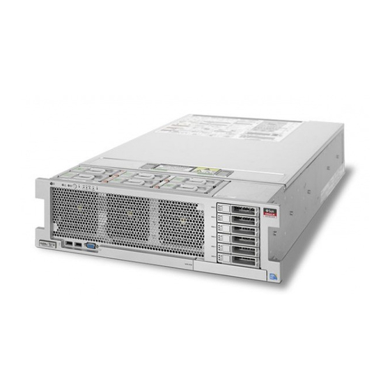
Server Overview Server Overview The Oracle Server X5-4 is a 3RU rack-mount server system. The following table lists the server-supported components. Component Description Processor (CPU) Intel Xeon® E7-8895 v3 18-core 2.6 GHz processor. Supported configurations: ■ Two processors installed in sockets 0 and 1 ■... -
Page 17: External Components And Features
■ Oracle Integrated Lights Out Manager (ILOM) on the Service Processor ■ Oracle System Assistant (OSA) on an optional internal USB flash drive ■ Oracle Hardware Management Pack. ■ Oracle Enterprise Management Ops Center, which can be downloaded from the Oracle site Service labels The system comes with two handy service labels for quick reference information. -
Page 18: Server Back Panel Features
Slots 0 and 1 support only SAS drives (mechanical or SSD). Slots 2–5 support both SAS and NVMe drives. Server Back Panel Features The following illustration shows the server back panel and describes its features. Oracle Server X5-4 Service Manual • December 2015... -
Page 19: Server Subsystems Overview
Server Subsystems Overview This section provides information about the server subsystems: “System Block Diagrams” on page 20 ■ “Processor Subsystem” on page 22 ■ “Memory Subsystem” on page 25 ■ “Cooling Subsystem” on page 25 ■ Oracle Server X5-4 Overview... -
Page 20: System Block Diagrams
The server can be configured with two or four CPUs. This section shows the system block diagrams for these two server configurations: “Two-CPU Block Diagram” on page 21 ■ “Four-CPU Block Diagram” on page 22 ■ Oracle Server X5-4 Service Manual • December 2015... -
Page 21: Two-Cpu Block Diagram
Server Subsystems Overview Two-CPU Block Diagram Oracle Server X5-4 Overview... -
Page 22: Processor Subsystem
Server Subsystems Overview Four-CPU Block Diagram Processor Subsystem The Oracle Server X5-4 uses the Intel Xeon E7-8895 v3 18-core 2.6 GHz processor and supports two CPU-based configurations: a two-CPU configuration and a four-CPU configuration. Oracle Server X5-4 Service Manual • December 2015... - Page 23 Callout Description Air baffle CPU P1 CPU P0 Memory riser card P1/MR1 Memory riser card P1/MR0 Memory riser card P0/MR1 Memory riser card P0/MR0 For more information, see “Two-CPU Block Diagram” on page Oracle Server X5-4 Overview...
- Page 24 The four-CPU configuration offers a greater level of resiliency with redundant QPI interconnects that allow working CPUs to route around a disabled CPU as the system starts. For more information, see “Four-CPU Block Diagram” on page Oracle Server X5-4 Service Manual • December 2015...
-
Page 25: Memory Subsystem
The internal components in the system are cooled by air that is pulled in through the front of the server and exhausted out the back of the server. Cooling occurs in two areas of the chassis, the power supply area and the motherboard area. Oracle Server X5-4 Overview... - Page 26 If one of the fan modules fails, the other fan module in the pair has sufficient power to cool the zone until the failed fan can be replaced. However, if both fan modules in a pair fail, Oracle ILOM will power off the system to prevent thermal damage. Pressure Areas The power supply and motherboard cooling areas have separate air pressures.
- Page 27 Temperature sensor TS_OUT (U4506) Cooling zone 2 Temperature sensor TS_TVL_1 (U4002) Cooling zone 3 (power supply Temperature sensor TS_TVL_0 backplane area) (U4302) Temperature sensor TS_PS (U4603) Temperature sensor TS_ZONE0_B (U4509) Temperature sensor TS_ZONE1 Temperature sensor TS_ZONE0_A (U4507) (U4508) Oracle Server X5-4 Overview...
-
Page 28: Power Subsystem
You can also apply full power to the server from Oracle ILOM. Once the server is operating in full power mode, the System OK and service processor (SP) indicators are on steady (see “Server Boot Process... - Page 29 A graceful shutdown (also referred to as an orderly shutdown) is the safest method of shutting down the server to standby power mode because it warns users, closes files, and prepares the file system. To perform a graceful shutdown, use the server OS, Oracle ILOM, or the server front panel Power button.
-
Page 30: Storage Subsystem
Server Subsystems Overview reset might be required after a software or firmware update or when you want to launch Oracle System Assistant or the BIOS Setup Utility. Cold Reset A cold reset occurs when you restart the server from a completely powered-off state. A cold reset might be required to resolve a system issue. -
Page 31: Input/Output (I/O) Subsystem
PCIe Gen-3 internal HBA has eight internal SAS3 ports that connect from the card to the system backplane through two bundled cables. When configured with NVMe SSD drives (up to four), the system must have one Oracle ■ PCIe NVMe Switch card (7111393) installed in PCIe slot 1. The NVMe switch card has four NVMe internal ports that connect from the card to the system disk backplane through four bundled cables. - Page 32 OS, server hardware configuration, and the firmware upgrade process. Do not use the Oracle System Assistant USB drive as the primary host boot device or as server storage. If installed in your server, the Oracle System Assistant USB drive must be installed in the port labeled "OSA USB."...
- Page 33 BIOS Solaris Linux Windows Net 3 8101 igb 3 eth 3 net 4 Net 2 8100 igb 2 eth 2 net3 Net 1 0701 igb 1 eth 1 net2 Net 0 0700 igb 0 eth 0 Oracle Server X5-4 Overview...
-
Page 34: System Management Subsystem
Oracle ILOM runs independently of the server OS and is accessible in both full power and standby power modes. The SP Oracle ILOM is accessible through the SP 100/1000/10000 Ethernet NET MGT port located on the server back panel or through one of the host's four built-in 10 GigabitEthernet ports (using sideband management). - Page 35 Protocol (SNMP). You can use this information to integrate your Oracle servers into your data center management infrastructure. Set up an Oracle ILOM trap proxy that forwards SNMP traps from your Oracle ILOM ■ service processor to the host OS.
- Page 36 Oracle Server X5-4 Service Manual • December 2015...
-
Page 37: Troubleshooting And Diagnostics
“Attaching Devices to the Server” on page 59 server to perform troubleshooting. Information on resetting the host or service “Resetting the Host or Service Processor” on page 63 processor (including the Oracle ILOM root password and account). Information about contacting Oracle support. “Getting Help” on page 66... -
Page 38: Troubleshooting Hardware Faults Using Oracle Ilom
(SEL). If you have set up notification through Oracle ILOM, you also receive an alert through the notification method you chose. When you become aware of a hardware fault, you should address it immediately. - Page 39 Troubleshooting Hardware Faults Using Oracle ILOM In the Status section of the summary screen, identify the server subsystem that requires service. In the above example, the Status screen shows that the Memory subsystem requires service. This indicates that a hardware component within the subsystem is in a fault state.
-
Page 40: Troubleshooting Using The Front Panel Indicators
To prepare the server for service. “Preparing to Service the Server” on page Service the component. After servicing the component, you might need to clear the fault in Oracle ILOM. For Note - more information, refer the component service procedure. - Page 41 Troubleshooting Hardware Faults Using Oracle ILOM “Locator Indicator On” on page 42 ■ “Over Temperature Condition” on page 42 ■ “PSU Failure” on page 43 ■ “Memory Failure” on page 43 ■ “CPU Failure” on page 44 ■ “Fan Module Failure” on page 44 ■...
- Page 42 The Locator indicator helps identify a server in a rack of servers. It can be activated remotely from Oracle ILOM or from the front panel (by pressing the Locator button). Once activated, the indicator blinks at the fast blink rate.
-
Page 43: Memory Failure
Troubleshooting Hardware Faults Using Oracle ILOM PSU Failure For a server with one of its PSU's in a failed state, the amber Service Action Required and PS REAR indicators are on steady. The green System OK indicator and the green SP indicator are on steady. - Page 44 For a server with a fan module fault, the amber Service Action Required and the FAN TOP indicators are on steady. The green OK indicator and the green SP indicator are on steady. For more information on fan indicators, see “Fan Module Reference” on page 135. Oracle Server X5-4 Service Manual • December 2015...
- Page 45 Troubleshooting Hardware Faults Using Oracle ILOM SP Failure For a server with an SP fault, the amber Service Action Required indicator is on steady. The green OK indicator and the green SP indicator are off. Front Panel Lamp Test To perform a lamp test of all front panel indicators, press and hold down the Locate button for at least five seconds.
- Page 46 For the steady on state, an indicator is continually on (lit) and does not blink. This indicates a continuing condition, for example, an operational state (green) or a Service Action Required fault state (amber). Oracle Server X5-4 Service Manual • December 2015...
- Page 47 Troubleshooting Hardware Faults Using Oracle ILOM Steady Off For the steady off state, an indicator is continually off (not lit) and does not blink. This indicates that a system is not operational, for example, no AC power (unlit green System OK indicator) or a subsystem not in a fault state (unlit amber Service Action Required indicator).
- Page 48 This indicates a component or system in standby mode. For example, the single blink rate occurs when a server is in standby power mode or a when hot spare device is waiting to be used (also used with amber indicators to indicate a predicted fault). Oracle Server X5-4 Service Manual • December 2015...
- Page 49 Troubleshooting Hardware Faults Using Oracle ILOM Slow Unison Blink Rate For the slow unison blink rate, the indicators on the component blink in unison for half a second during a one second interval (1 Hz). Typically, this is limited to three successive blinks. This confirms the successful insertion of a removable device (for example, a storage drive or blade) into a powered system (confirming the power connection).
- Page 50 (for example, a power supply with a lower rating than the one specified). Also used for an unsupported component, a component in an unsupported slot, or a blade (server module) that causes a power supply to be oversubscribed for that system. Oracle Server X5-4 Service Manual • December 2015...
-
Page 51: Troubleshooting Using The Fault Remind Test Circuits
Troubleshooting Hardware Faults Using Oracle ILOM Feedback Flash An indicator flashes on and off during periods of activity, commensurate with the activity, but flashing does not exceed the 2 Hz fast blink rate (see, “Fast Blink Rate” on page 48). -
Page 52: Troubleshooting System Cooling Issues
Prevention: Periodically check the ambient temperature of the server space to ensure that it is within the required range, especially if you have made any changes to the server space (for example, added additional servers). The temperature must be consistent and stable. Oracle Server X5-4 Service Manual • December 2015... - Page 53 Troubleshooting Hardware Faults Using Oracle ILOM Airflow Blockage The server cooling system uses fans to pull cool air in from the server front intake vents and exhaust warm air out the server back panel vents. If the front or back vents are blocked, the airflow through the server is disrupted and the cooling system fails to function properly causing the server internal temperature to rise.
-
Page 54: Troubleshooting Power Issues
Action: Check that both AC power cords are connected to the server and check that the correct power is present at the outlets. If necessary, monitor the power to verify that it is within the Oracle Server X5-4 Service Manual • December 2015... - Page 55 Troubleshooting Hardware Faults Using Oracle ILOM acceptable range. You can verify proper connection and operation of a power supply by checking its indicator panel. A properly installed PSU has its green AC OK indicator lit. A properly functioning PSU has its green power (DC) OK indicator lit and its amber Service Action Required indicator off.
-
Page 56: Top Cover
When servicing the server, take care that the internally mounted interlock switch component does not get damaged or misaligned. Never operate the server without the top cover installed. Oracle Server X5-4 Service Manual • December 2015... -
Page 57: Troubleshooting With Diagnostic Tools
(while at the server) or remotely. The selection of diagnostic tools available for your server range in complexity from a comprehensive validation test suite (Oracle VTS) to a chronological event log (Oracle ILOM System Log). The selection of diagnostic tools also include standalone software packages, firmware-based tests, and hardware-based LED indicators. -
Page 58: Diagnostic Tool Documentation
The following table identifies where you can find more information about diagnostic tools. Diagnostic Information Location Tool Oracle ILOM Oracle Integrated Lights Out Manager 3.2 http://www.oracle.com/goto/ILOM/docs Documentation Library Preboot Menu Oracle x86 Servers Diagnostics Guide http://www.oracle.com/goto/ x86AdminDiag/docs Oracle Server X5-4 Service Manual • December 2015... -
Page 59: Attaching Devices To The Server
Connect an Ethernet cable to the Gigabit Ethernet (NET) connectors. “Back Panel Connector Locations” on page To connect to Oracle ILOM over the network, connect an Ethernet cable to the Ethernet port labeled NET MGT. “Back Panel Connector Locations” on page... -
Page 60: Back Panel Connector Locations
Attach Devices to the Server To access the Oracle ILOM command-line interface (CLI) locally using the management port, connect a serial null modem cable to the RJ-45 serial port labeled SER MGT. “Back Panel Connector Locations” on page To interact with the system console locally, connect a monitor [1], keyboard [2] and mouse [3] to the server front panel connectors as shown in the illustration below. -
Page 61: Configuring Serial Management Port Ownership
By default, the service processor (SP) uses the serial management port (SER MGT) for serial console output. Using Oracle ILOM, you can specify that the host be assigned as owner of the serial management port (configured as COM1). This feature is useful for Windows kernel debugging, as it enables you to view non-ASCII character traffic from the host console. - Page 62 CLI or web interface to change the serial port owner back to the SP. To return the serial port owner setting back to the SP, use the network connection to Oracle ILOM.
-
Page 63: Resetting The Host Or Service Processor
CLI or web interface to change the serial port owner back to the SP. To return the serial port owner setting back to the SP, use the network connection to Oracle ILOM. -
Page 64: Reset The Host Or Sp Using Oracle Ilom
From the Oracle ILOM web interface, click ILOM Administration > ■ Maintenance > Reset SP. Resetting the Oracle ILOM SP disconnects your current Oracle ILOM session. You must Note - log in again to continue working in Oracle ILOM. Reset the host using one of the following methods: From the Oracle ILOM CLI, enter the command: ■... -
Page 65: Reset The Sp Root Account Password Or Recover The Root Account
To perform either action, you need a local serial management port (SER MGT) connection to Oracle ILOM. In addition, if the Physical Presence State is enabled (the default) in Oracle ILOM, you must prove that you are physically present at the server as described in the following procedure. -
Page 66: Getting Help
For additional information logging in through the serial management port, see “Log In to Oracle ILOM CLI Using a Local Serial Connection” in Oracle Server X5-4 Installation Guide. To prove physical presence at the server, press the Locator button on the front of the server. -
Page 67: Locating The System Serial Number
■ From the Oracle ILOM command-line interface (CLI), type the command: show/SYS. ■ From the Oracle ILOM web interface, view the serial number in the System Information ■ tab. From Oracle System Assistant, view the serial number in the System Overview (home ■... - Page 68 Oracle Server X5-4 Service Manual • December 2015...
-
Page 69: Servicing The Server
“Locating a Failed Memory Riser Card, DIMM, or CPU” on page 82 remind test circuits. Procedures about clearing “Clear Hardware Fault Messages” on page 91 hardware faults in Oracle ILOM. Component Serviceability, Locations, and Designations This section describes component service designations, serviceability, and locations. “Component Serviceability” on page 70 ■... -
Page 70: Component Serviceability
(CRU) or a field-replaceable unit (FRU). A part designated as a FRU must be replaced by an Oracle-qualified service technician. ■ A part designated as a CRU can be replaced by a person who is not an Oracle-qualified ■ service technician. - Page 71 Component Serviceability, Locations, and Designations “Replaceable Components” on page 71 ■ “Components (Exploded View)” on page 72 ■ Replaceable Components Callout Description Callout Description Motherboard HBA SAS cables (2) SP card Storage drive backplane board HBA card Heatsinks and CPUs (2 or 4) PCIe NVMe Switch card Memory riser cards (4 or 8) Power supplies (2)
- Page 72 Component Serviceability, Locations, and Designations Callout Description Callout Description Storage drive slots (6) NVMe cables (4) Components (Exploded View) Callout Description Callout Description Power supplies Air baffle (2-CPU configuration only) Oracle Server X5-4 Service Manual • December 2015...
-
Page 73: Component Designations
Component Serviceability, Locations, and Designations Callout Description Callout Description Power supply backplane board Motherboard SP card Storage drive System battery DVD drive PCIe NVMe Switch card Fan module HBA card Fan board Storage drive backplane board Heatsink Server chassis Cover ESM (Energy Storage Module for HBA) Memory riser card... - Page 74 P0/MR0 and P0/MR1. Slots 2 and 3 are paired with CPU socket, P1 and are designated as P1/MR0 and P1/MR1. This numbering pattern continues for the remaining slots. Oracle Server X5-4 Service Manual • December 2015...
- Page 75 Component Serviceability, Locations, and Designations Callout Description Callout Description MR card slot P3/MR1 MR card slot P0/MR1 MR card slot P3/MR0 MR card slot P0/MR0 MR card slot P2/MR1 CPU-3 (P3) MR card slot P2/MR0 CPU-2 (P2) MR card slot P1/MR1 CPU-1 (P1) MR card slot P1/MR0 CPU-0 (P0)
- Page 76 The slots are accessible from the back of the server. From the back of the server, the left slot is designated as PS-0, and the right slot is PS-1. Oracle Server X5-4 Service Manual • December 2015...
- Page 77 Component Serviceability, Locations, and Designations Callout Description PS 1 PS 0 PCIe Slot Designations The eleven PCIe slots are located inside the server at the back. As viewed from the front of the server, the slots are divided into two groups, a group of six on the right of the SP card and a group of five on the left of the SP card.
- Page 78 The bottommost slot is designated as HDD-0, and the topmost slot is HDD- The two internal USB slots are located between the disk backplane board and the power supply backplane board. An optional Oracle System Assistant flash drive is installed in the port marked "OSA USB."...
-
Page 79: Performing Electrostatic Discharge And Static Prevention Measures
Performing Electrostatic Discharge and Static Prevention Measures Callout Description Callout Description HDD5/NVMe3 HDD0 HDD4/NVMe2 HDD3/NVMe1 OSA USB port HDD2/NVMe0 USB port HDD1 Performing Electrostatic Discharge and Static Prevention Measures Electrostatic discharge (ESD) sensitive devices, such as the PCIe cards, hard drives, CPUs, and memory cards, require special handling. -
Page 80: Using An Anti-Static Wrist Strap
ESD-sensitive components such as printed circuit boards, DIMMs, and CPUs. You can use the following items as anti-static mats: Oracle Server X5-4 Service Manual • December 2015... -
Page 81: Tools And Equipment
Tools and Equipment Anti-static bag used to wrap a replacement part ■ ESD mat (orderable from Oracle) ■ A disposable ESD mat (shipped with some optional system components) ■ Tools and Equipment To service the system, you need the following tools: No. -
Page 82: Locating A Failed Memory Riser Card, Dimm, Or Cpu
This section describes the locations of the system Fault Remind circuit components: “System Fault Remind Button and Charge Status Indicator” on page 83 ■ “Memory Riser Card and CPU Fault Indicators” on page 83 ■ “CPU Fault Indicators” on page 84 ■ Oracle Server X5-4 Service Manual • December 2015... - Page 83 Locating a Failed Memory Riser Card, DIMM, or CPU System Fault Remind Button and Charge Status Indicator The Fault Remind Button is located on the divider between the cooling zone 1 and cooling zone 2. The Charge Status Indicator is located next to the button. Memory Riser Card and CPU Fault Indicators The memory riser card Fault indicators are visible through the small hole on top of the card.
- Page 84 CPU Fault indicators. When a CPU fails the fault indicators of its two memory riser cards also light, making it Note - easier to identify the failed CPU. Oracle Server X5-4 Service Manual • December 2015...
-
Page 85: Dimm Fault Remind Circuit Components
Locating a Failed Memory Riser Card, DIMM, or CPU Callout Description CPU Fault indicators DIMM Fault Remind Circuit Components The DIMM Fault Remind Test Circuit is located on the memory riser card. The Fault Remind Button and Charge Status Indicator are located near the right-side bank of DIMM slots at the front edge of the card. -
Page 86: Locate A Failed Memory Riser Card, Dimm, Or Cpu
The test circuits are charged, time-limited circuits. Once power is removed from the Note - server you have 10 minutes to use the DIMM Fault Remind circuit and 30-60 minutes to use the System Fault Remind circuit. Prepare for service. Oracle Server X5-4 Service Manual • December 2015... - Page 87 Locate a Failed Memory Riser Card, DIMM, or CPU “Prepare the Server for Cold Service” on page Press and hold the system Fault Remind button. The Fault Remind button is located on the divider between the cooling zone 1 and cooling zone Verify that the system Fault Remind circuit is usable.
- Page 88 When an MR card is in a fault state, the Fault indicator for the card lights when the system Fault Remind button is pressed. The indicator is visible through the small hole on top of the card. Oracle Server X5-4 Service Manual • December 2015...
- Page 89 Locate a Failed Memory Riser Card, DIMM, or CPU The following illustration shows a lit Fault indicator for memory riser card, P1/MR1. For more information, see “Memory Riser Card and CPU Fault Indicators” on page To locate a failed DIMM, look for an MR card Fault indicator. ■...
- Page 90 Memory Riser Card” on page 144. “Replace a Faulty CPU (FRU)” on page 180 Next Steps ■ “Remove a Memory Riser Card” on page 145 ■ “Replace a Faulty DIMM” on page 143 ■ Oracle Server X5-4 Service Manual • December 2015...
-
Page 91: Clear Hardware Fault Messages
If a component fault needs to be manually cleared, use the fmadm command from the Oracle ILOM Fault Management shell. The Fault Management shell is accessible by logging in to the Oracle ILOM CLI. For events logged in the Oracle ILOM event log, use the Oracle ILOM web interface. - Page 92 -u uuid – Show fault diagnosis events that match a specific universal unique identifier ■ (uuid). For command specifics, see the Oracle ILOM User's Guide for System Monitoring and Diagnostics for your version of Oracle ILOM at: http://www.oracle.com/goto/ILOM/docs Use fmadm to clear the fault.
-
Page 93: Preparing To Service The Server
Preparing to Service the Server This section provides procedures for preparing the server for service. Description Links Procedural information for preparing to “Prepare the Server for Hot Service” on page 93 perform hot service on the server. Procedural information for preparing to “Prepare the Server for Cold Service”... -
Page 94: Prepare The Server For Cold Service
To log in, open a web browser and direct it using the IP address of the server SP. Log in as root or a user with administrator privileges. For more information, refer to the Oracle X5 Series Servers Administration Guide at http://www.oracle.com/goto/x86AdminDiag/docs. - Page 95 Log in to the Oracle ILOM web interface. Type the server SP IP address into a web browser and log in as a user with root or administrator privileges. For more information, refer to the Oracle X5 Series Servers Administration Guide at http://www.oracle.com/goto/x86AdminDiag/docs.
- Page 96 The cable management arm (CMA) that is supplied with the server is hinged to facilitate extending the server to the maintenance position. Ensure the sliding movement does not impede or damage the cables. If necessary, label and remove cables from the back of the server. Oracle Server X5-4 Service Manual • December 2015...
- Page 97 Prepare the Server for Cold Service (Optional) Release and reposition the CMA to access to the back of the server. “Release the CMA” on page At the front of the server, release the slide rails by pushing the two green latches inward.
-
Page 98: Release The Cma
“Servicing FRU Components” on page 179 ■ Release the CMA If you are using a cable management arm (CMA), to gain additional access to the back of the server, release and reposition the CMA. Oracle Server X5-4 Service Manual • December 2015... -
Page 99: (Optional) Remove The Server From The Rack
(Optional) Remove the Server from the Rack Press and hold the tab. Swing the CMA away from the server. (Optional) Remove the Server from the Rack To perform some service procedures, you might find it necessary or more convenient to completely remove the server from the rack, rather than work on the server while it is the maintenance position. - Page 100 Do not touch or handle components unless you are wearing a properly grounded anti-static wrist strap. “Performing Electrostatic Discharge and Static Prevention Measures” on page Pull the mounting release brackets [1] toward the front of the server. Oracle Server X5-4 Service Manual • December 2015...
-
Page 101: Powering Off The Server
Powering Off the server The brackets are located on each side of the server. This action releases the server from the rails. Using multiple personnel, slide the server entirely out of the rack. Slide the server out of the rack and onto a mechanical lift. Place the server chassis on an anti-static mat before servicing internal components. -
Page 102: Power Off The Server Using The Server Os
OS. Non-ACPI enabled operating systems might ignore this event and not shut down the host. If your OS ignores this event, shut down the server using the server OS or Oracle ILOM. Use this procedure to perform a graceful power off and place the server in standby power mode. -
Page 103: Power Off, Immediate (Power Button)
Power Off, Immediate (Power Button) Potential for loss of data. Do not press in and hold the power button for longer than Caution - five seconds. Doing so initiates an immediate server shutdown. Press in and release the button immediately. Verify that the server is in standby power mode. -
Page 104: Power Off, Remote (Oracle Ilom Cli)
See Also ■ Power Off, Remote (Oracle ILOM CLI) You can use the Oracle ILOM SP command-line interface (CLI) to remotely power off the server to standby power mode. Open an SSH session and log in to the Oracle ILOM CLI. -
Page 105: Power Off, Remote (Oracle Ilom Web Interface)
Power Off, Remote (Oracle ILOM Web Interface) You can use the Oracle ILOM web interface to remotely power off the server to standby power mode. Log in to the Oracle ILOM web interface. To log in, open a web browser and enter the IP address of the server SP. Log in as root or a user with administrator privileges. -
Page 106: Remove Power
Extend the server to the maintenance position. Position the CMA. Access the back of the server. Remove the power cord retainer clips by lifting them up to disengage them from the power cords. Oracle Server X5-4 Service Manual • December 2015... -
Page 107: Managing The Locator Indicator
Oracle ILOM, and locally using the front panel Locator button. “Turn On the Locator Indicator Remotely (Oracle ILOM CLI)” on page 108 ■ “Turn On the Locator Indicator Remotely (Oracle ILOM Web Interface)” on page 109 ■ “Manage the Locator Indicator Locally” on page 110 ■... -
Page 108: Turn On The Locator Indicator Remotely (Oracle Ilom Cli)
The Locator indicator helps you identify the a specific server in a rack. Open an SSH session and at the command line log in to the Oracle ILOM CLI. Log in as a user with root or administrator privileges. For example:... -
Page 109: Turn On The Locator Indicator Remotely (Oracle Ilom Web Interface)
To log in, open a web browser and direct it using the IP address of the server SP. Log in as root or a user with administrator privileges. For more information, refer to the Oracle X5 Series Servers Administration Guide at http://www.oracle.com/goto/x86AdminDiag/docs. -
Page 110: Manage The Locator Indicator Locally
■ To turn on the Locator indicator, press the Locator indicator button. ■ Some Oracle ILOM security procedures require that you turn on the Locator indicator Note - locally, as part of a physical presence verification step. To perform a lamp test of all front panel indicator LEDs, press the Locator ■... - Page 111 Remove the Server Cover high-voltage areas inside the server. It also prevents an over-temperature condition which would result from a disruption of the server cooling system. Removing the cover when the server is powered on performs an immediate power off of the server, which can cause loss of data and possible component damage.
- Page 112 Component damage. Part of the power interlock switch is mounted on the underside Caution - of the cover It can be damaged (or misaligned) if the cover is dropped or the component jarred. Take care not to damage the switch. Oracle Server X5-4 Service Manual • December 2015...
-
Page 113: Servicing Cru Components
Servicing CRU Components This section provides procedures for replacing and installing customer-replaceable units (CRUs). Description Link Server storage drives “Servicing Storage Drives (CRU)” on page 113 Fan modules “Servicing Fan Modules (CRU)” on page 130 Power supplies “Servicing Power Supplies (CRU)” on page 137 Memory riser cards and DIMMs “Servicing Memory Riser Cards and DIMMs (CRU)”... -
Page 114: Storage Drives Hot-Plug Conditions
If optional NVMe drives are part of the RAID, special replacement instructions must be followed to prevent an operating system crash. See: “Removing and Replacing an NVMe Storage Drive Using Oracle Solaris” on page 121 ■ “Removing and Replacing an NVMe Storage Drive Using Oracle Linux” on page 125 ■... -
Page 115: Nvme Storage Drive Virtual Pcie Slot Designation
Remove a Storage Drive Filler Panel (CRU) NVMe Storage Drive Virtual PCIe Slot Designation If NVMe storage drives are installed, they are labeled on the system front panel as NVMe0, NVMe1, NVMe2, and NVMe3. However, the server BIOS internally identifies these drives by their virtual PCIe slot numbers. - Page 116 “Prepare the Server for Hot Service” on page To hot-plug an NVMe drive: ■ Use operating system commands to prepare the drive for removal: “Removing and Replacing an NVMe Storage Drive Using Oracle ■ Solaris” on page 121 “Removing and Replacing an NVMe Storage Drive Using Oracle ■...
- Page 117 Remove a Storage Drive (CRU) Power off the server. Use one of the power-off options described in “Prepare the Server for Cold Service” on page Once physically at the server, If necessary, press the Locator indicator button to deactivate the indicator. Identify the storage drive you want to remove.
-
Page 118: Install A Storage Drive (Cru)
“Prepare the Server for Cold Service” on page ■ Verify that the release lever on the storage drive is fully opened. Slide the drive into the drive slot until it is fully seated. Oracle Server X5-4 Service Manual • December 2015... -
Page 119: Install A Storage Drive Filler Panel (Cru)
If you have replaced an NVMe drive using a hot-service procedure, refer to ■ the following for powering on the device: “Removing and Replacing an NVMe Storage Drive Using Oracle ■ Solaris” on page 121 “Removing and Replacing an NVMe Storage Drive Using Oracle ■... - Page 120 Service Action Required Indicator Amber indicator. Indicates that the storage drive is faulty. The front and back panel Service Action Required indicators are also lit if the system detects a storage drive fault. Oracle Server X5-4 Service Manual • December 2015...
-
Page 121: Removing And Replacing An Nvme Storage Drive Using Oracle Solaris
“Servicing Storage Drives (CRU)” on page 113 Removing and Replacing an NVMe Storage Drive Using Oracle Solaris NVMe storage drives are only supported on servers running the Oracle Solaris or Oracle Note - Linux operating system. Servers running Oracle VM, Windows Server, Red Hat Enterprise Linux, SUSE Linux Enterprise Server, or VMware ESXi do not support NVMe drives. - Page 122 Path ------------------------------------------------------- pcie100 PRESENT PCIe-Native /pci@0,0/pci8086,2f06@2,2/pci111d,80b5@0/pci111d,80b5@4 pcie101 ENABLED PCIe-Native /pci@0,0/pci8086,2f06@2,2/pci111d,80b5@0/pci111d,80b5@5 pcie102 ENABLED PCIe-Native /pci@0,0/pci8086,2f06@2,2/pci111d,80b5@0/pci111d,80b5@6 pcie103 ENABLED PCIe-Native /pci@0,0/pci8086,2f06@2,2/pci111d,80b5@0/pci111d,80b5@7 Verify that the blue OK to Remove indicator on the NVMe drive is lit. Oracle Server X5-4 Service Manual • December 2015...
-
Page 123: Remove An Nvme Storage Drive From The Server
Remove an NVMe Storage Drive From the Server Remove an NVMe Storage Drive From the Server Perform this procedure to physically remove an NVMe storage drive from the server. Identify the physical location of the NVMe drive that you want to remove. For storage drive locations, see “DVD, Storage Drive, and USB Designations”... -
Page 124: Install An Nvme Storage Drive In The Server
PCIe slot name is not the same as the name on the server front panel label. Power on the slot for the drive. Type: hotplug enable pcie100 In this example, pcie100 is the drive labeled NVMe0 on the server front panel. Oracle Server X5-4 Service Manual • December 2015... -
Page 125: Removing And Replacing An Nvme Storage Drive Using Oracle Linux
■ Removing and Replacing an NVMe Storage Drive Using Oracle Linux NVMe storage drives are only supported on servers running the Oracle Solaris or Oracle Note - Linux operating system. Servers running Oracle VM, Windows Server, Red Hat Enterprise Linux, SUSE Linux Enterprise Server, or VMware ESXi do not support NVMe drives. -
Page 126: Prepare An Nvme Storage Drive For Removal
115. Note that the virtual PCIe slot name is not the same as the name on the server front panel label. Log in to Oracle Linux that is running on the server. Obtain information about available NVMe storage devices. Obtain the PCIe addresses (Bus Device Function) of enabled NVMe drives. - Page 127 Prepare an NVMe Storage Drive for Removal This commands returns output similar to the following: /sys/bus/pci/slots/100/address:0000:12:00 /sys/bus/pci/slots/101/address:0000:13:00 /sys/bus/pci/slots/102/address:0000:14:00 /sys/bus/pci/slots/103/address:0000:15:00 For example, the PCIe address 0000:12:00.0 matches the PCIe slot number (100) for the drive labeled NVMe0 on the system front panel. Remove the NVMe storage device path.
-
Page 128: Remove An Nvme Storage Drive From The Server
# lspci -nnd :0953 13:00.0 Non-Volatile memory controller [0108]: Intel Corporation Device [8086:0953] (rev 14:00.0 Non-Volatile memory controller [0108]: Intel Corporation Device [8086:0953] (rev 15:00.0 Non-Volatile memory controller [0108]: Intel Corporation Device [8086:0953] (rev Oracle Server X5-4 Service Manual • December 2015... -
Page 129: Install An Nvme Storage Drive In The Server
Install an NVMe Storage Drive In the Server Note that address 12:00.0, which represents PCIe slot 100 and is the drive labeled NVMe0 on the system front panel and the drive powered off in the example shown in “Prepare an NVMe Storage Drive for Removal”... -
Page 130: Servicing Fan Modules (Cru)
As an option, you can also perform this procedure using cold service. For serviceability considerations, see “Component Serviceability” on page Before You Begin ■ For fan module designation information, see “Component Designations” on page ■ Oracle Server X5-4 Service Manual • December 2015... - Page 131 Remove a Fan Module Prepare the server: For hot service, see “Prepare the Server for Hot Service” on page ■ For cold service, see “Prepare the Server for Cold Service” on page ■ If necessary, slide the server partially out from the rack. At the back of the server, verify that the cables have sufficient length and clearance to extend the server.
- Page 132 When removing a fan module, do not rock it back and forth. “Install a Fan Module” on page 133 Next Steps Oracle Server X5-4 Service Manual • December 2015...
-
Page 133: Install A Fan Module
Install a Fan Module Install a Fan Module This procedure describes how to install a replacement fan module in the server. For serviceability considerations, see “Component Serviceability” on page Before You Begin ■ For fan module designation information, see “Component Designations” on page ■... - Page 134 “Server Front Panel Features” on page 17 “Server Back Panel Features” on page 18 locations of system indicators. If necessary, return the server to the normal rack position. Oracle Server X5-4 Service Manual • December 2015...
-
Page 135: Fan Module Reference
Install a Fan Module Ensure the cables are free from binding and pinching. Slide the server into the rack until it locks into place. If you performed a cold-service procedure, power on the server. Fan Module Reference The six fan modules are located at the front of the chassis and provide cooling for the three motherboard cooling zones (for more information, see “Cooling Subsystem”... - Page 136 Service Action Required Indicator Amber indicator. The fan module is faulty. The server front and back panel Service Action Required indicators are also lit if the system detects a fan module fault. Oracle Server X5-4 Service Manual • December 2015...
-
Page 137: Servicing Power Supplies (Cru)
Servicing Power Supplies (CRU) Servicing Power Supplies (CRU) The following sections provide procedures for removing and installing a power supply. “Remove a Power Supply” on page 137 ■ “Install a Power Supply” on page 138 ■ “Power Supply Reference” on page 140 ■... -
Page 138: Install A Power Supply
PSU bay. The pawl supplies the necessary leverage to seat the PSU connector with the PSU backplane. Oracle Server X5-4 Service Manual • December 2015... - Page 139 Install a Power Supply System overheat and shut down. Installing the incorrect model of power supply can Caution - cause the server to over heat. Install only the supported model. For serviceability considerations, see “Component Serviceability” on page Before You Begin ■...
-
Page 140: Power Supply Reference
Rear PS Fault indicator on the front bezel of the server ■ Service Action Required indicator on the faulty power supply ■ “Server Front Panel Features” on page 17 “Server Back Panel Features” on page 18 locations of system indicators. Oracle Server X5-4 Service Manual • December 2015... - Page 141 Install a Power Supply Callout Description Amber Service Action Required Green DC OK Green AC OK Service Action Required Indicator Amber indicator. Indicates that the power supply is faulty and service-related action is required. Servicing CRU Components...
-
Page 142: Servicing Memory Riser Cards And Dimms (Cru)
Use the following procedures to remove and install memory risers, DIMMs, and filler panels. “Replace a Faulty DIMM” on page 143 ■ “Replace a Faulty Memory Riser Card” on page 144 ■ “Remove a Memory Riser Card” on page 145 ■ Oracle Server X5-4 Service Manual • December 2015... - Page 143 Replace a Faulty DIMM “Identify a Faulty DIMM” on page 146 ■ “Remove a DIMM” on page 148 ■ “Install a DIMM” on page 150 ■ “Install a Memory Riser Card” on page 152 ■ Replace a Faulty DIMM Use this procedure to replace a faulty DIMM. When servicing the components in this section, unplug the AC power cords and use ESD protection.
- Page 144 Make note of the DIMM population configuration on the faulty card. You must replicate this same DIMM population configuration on the replacement card. The slots are color coded. For more information, see “Memory Riser Card and DIMM Reference” on page 154. Oracle Server X5-4 Service Manual • December 2015...
- Page 145 Remove a Memory Riser Card Ensure that you replicate the same DIMM configuration on the replacement card. Note - Transfer the DIMMs from the slots on the faulty MR card to the same slots on the replacement card: Transfer the DIMMs from the faulty card to the replacement card one at a time. Tip - Remove a DIMM from the faulty MR card.
- Page 146 “Install a DIMM” on page 150 ■ -or- “Replace the Motherboard (FRU)” on page 247 ■ Identify a Faulty DIMM When servicing the components in this section, unplug the AC power cords and use ESD protection. Oracle Server X5-4 Service Manual • December 2015...
- Page 147 Use Oracle ILOM to identify the failed DIMM in the system. “Troubleshooting Hardware Faults Using Oracle ILOM” on page 38 Oracle ILOM can provide the memory riser card and DIMM designations for the failed DIMM. If Oracle ILOM is showing multiple DIMMs in a failed state, see “Troubleshooting...
-
Page 148: Remove A Dimm
When servicing the components in this section, unplug the AC power cords and use ESD protection. DIMMs are cold-service components. The server must be completely removed from its Note - power source. Oracle Server X5-4 Service Manual • December 2015... - Page 149 Remove a DIMM Use this procedure to remove a DIMM from its slot on the memory riser (MR) card. For serviceability considerations, see “Component Serviceability” on page Before You Begin ■ For DIMM designation information, see “Component Designations” on page ■...
-
Page 150: Install A Dimm
Align the notch on the DIMM with the protrusion on the DIMM slot to ensure that the DIMM is installed correctly. Gently and evenly push the DIMM into the slot until the ejector levers rise and lock the DIMM into place. Oracle Server X5-4 Service Manual • December 2015... - Page 151 Install a DIMM The levers rise as the DIMM is pushed further into the slot. Ensure that the levers have risen completely and have locked the DIMM in the slot. Repeat the above steps until all replacement DIMMs are installed. Component damage.
- Page 152 The DIMMs on the card must face the left (when looked at from the front of the server). Carefully lower the card on to the slot. Ensure that the card is in the provided card guide channels. See the illustration below. Oracle Server X5-4 Service Manual • December 2015...
- Page 153 Install a Memory Riser Card To seat the card into the slot, firmly push down on the green "Press here to insert" label on the metal bracket on top of the card. This action seats the card in the connector on the motherboard. Prepare the server for operation.
-
Page 154: Memory Riser Card And Dimm Reference
“Troubleshooting a Multi-DIMM Failure State” on page 159 ■ Memory Riser Card Components The following illustration shows the components of the memory riser card. Callout Description Callout Description Connector DIMM ejector/locking levers (two on each slot) Oracle Server X5-4 Service Manual • December 2015... - Page 155 Install a Memory Riser Card Callout Description Callout Description DIMM slots (12) Charge status indicator (green) Fault Remind button Memory riser card fault indicator DIMM fault indicators Memory Riser Cards Physical Layout The memory riser cards are located behind the fan module bay. The designations each memory riser (MR) card and its associated CPU are located inside the server on labels affixed to the rear MR card bracket.
- Page 156 First populate riser slot MR0 for each CPU, starting with the lowest numbered CPU ■ (P0). Then populate riser slot MR1 for each CPU, starting with the lowest numbered CPU ■ (P0). Oracle Server X5-4 Service Manual • December 2015...
- Page 157 Install a Memory Riser Card Supported DIMMs and DIMM Population Rules This section describes the supported DIMM configuration and population rules for memory risers in the system. Use only Oracle supported DIMMs in the system. Supported configurations: Minimum supported configuration: ■...
- Page 158 (black/white slots), or white slot with white levers (white/white slots) as shown in the following illustration: Call Out Description Slots Levers Memory Riser layout: The following illustration shows the DIMM slot and channel designations on the memory riser card: Oracle Server X5-4 Service Manual • December 2015...
- Page 159 When a DIMM failure occurs, check the Oracle ILOM system event log (SEL) to: Identify the first DIMM that failed.
-
Page 160: Servicing Pcie Cards
■ “PCIe Slot Reference” on page 167 ■ The factory installed Oracle Storage 12 Gb/s SAS RAID PCIe HBA (Internal) and Note - Oracle NVMe Switch PCIe card are only serviceable by Oracle Service personnel, see “Servicing the Factory Installed SAS 12 Gb/s Internal HBA and ESM” on page 200 “Servicing the Factory Installed PCIe NVMe Switch Card”... -
Page 161: Remove A Pcie Card
Remove a PCIe Card Remove a PCIe Card When servicing the components in this section, unplug the AC power cords and use ESD protection. Component damage. Ensure that all power is removed from the server before Caution - removing or installing expansion cards. You must disconnect the power cables before performing this procedure. - Page 162 Remove a PCIe Card To disengage the PCIe card retaining bar, push down on the bar, move it away from the server back wall, and lift it to an upright position. Oracle Server X5-4 Service Manual • December 2015...
- Page 163 Remove a PCIe Card Carefully remove the PCIe card from the PCIe card slot. Server over temperature. Whenever you remove a PCIe card, you should replace it Caution - with another PCIe card or a filler panel; otherwise, the server might overheat. If you are not installing a card in the slot, install a PCIe slot filler.
-
Page 164: Install A Pcie Card
For PCIe slot designation information, see “Component Designations” on page ■ Unpack the PCIe card and place it on an antistatic mat. Prepare the server for service. “Prepare the Server for Cold Service” on page Oracle Server X5-4 Service Manual • December 2015... - Page 165 Install a PCIe Card To disengage the PCIe card retaining bar, push down on the bar, move it away from the server back wall, and lift it to an upright position. If the slot has a PCIe filler panel, remove it. Install the PCIe card into the PCIe card slot.
- Page 166 Prepare the server for operation. “Prepare the Server for Operation” on page 259. If the PCIe card being installed is replacing a faulty PCIe card, manually clear the PCIe card fault using Oracle ILOM. Oracle Server X5-4 Service Manual • December 2015...
-
Page 167: Pcie Slot Reference
Install a PCIe Card “Clear Hardware Fault Messages” on page Configure the PCIe card, as needed. “Replace the Motherboard (FRU)” on page 247 See Also ■ PCIe Slot Reference This section describesPCIe slot information. “PCIe Slot Length and Capabilities” on page 167 ■... -
Page 168: Servicing The Dvd Drive (Cru)
“Install the DVD Drive or DVD Drive Filler Panel” on page 170 ■ Remove the DVD Drive or DVD Drive Filler Panel When servicing the components in this section, unplug the AC power cords and use ESD protection. Oracle Server X5-4 Service Manual • December 2015... - Page 169 Remove the DVD Drive or DVD Drive Filler Panel Component damage. Ensure that all power is removed from the server before Caution - removing or installing the DVD drive. You must disconnect the power cables before performing this procedure. This procedure describes how to remove the DVD drive or a DVD drive filler panel. For serviceability considerations, see “Component Serviceability”...
-
Page 170: Install The Dvd Drive Or Dvd Drive Filler Panel
“Install the DVD Drive or DVD Drive Filler Panel” on page 170 Next Steps Install the DVD Drive or DVD Drive Filler Panel When servicing the components in this section, unplug the AC power cords and use ESD protection. Oracle Server X5-4 Service Manual • December 2015... - Page 171 Install the DVD Drive or DVD Drive Filler Panel Component damage. Ensure that all power is removed from the server before Caution - removing or installing the DVD drive. You must disconnect the power cables before performing this procedure. This procedure describes how to install the DVD drive or a DVD drive filler panel. “Remove the DVD Drive or DVD Drive Filler Panel”...
-
Page 172: Replace The System Battery (Cru)
Slide the DVD drive or filler panel into the front of the chassis until it seats. Prepare the server for operation. “Prepare the Server for Operation” on page 259. Replace the System Battery (CRU) This section provides instructions for replacing the server system (RTC) battery. Oracle Server X5-4 Service Manual • December 2015... - Page 173 Replace the System Battery (CRU) When servicing the components in this section, unplug the AC power cords and use ESD protection. The system battery maintains system time when the server is off or disconnected from AC power. Use the following procedures to remove and replace the system battery when it has failed.
- Page 174 (negative side) toward the metal tab (on the positive side) and lifting the battery up and out of the battery holder. Take care not to deform the tab when pushing against it. Oracle Server X5-4 Service Manual • December 2015...
- Page 175 Replace the System Battery (CRU) Component damage. Do not deform the metal tab on the positive side of the battery. Caution - The metal tab maintains the positive battery connection and secures the battery in the holder. Press the new battery into the battery holder with the positive side facing the metal tab that holds it in place.
- Page 176 ILOM clock using the Oracle ILOM CLI or the web interface. If the service processor is configured to synchronize with a network time server using the Network Time Protocol (NTP), the Oracle ILOM clock resets as soon as the server is powered on and connected to the network.
- Page 177 Replace the System Battery (CRU) Refer to “BIOS Setup Utility Menu Options” on page 273 for information about using the BIOS Setup Utility. Servicing CRU Components...
- Page 178 Oracle Server X5-4 Service Manual • December 2015...
-
Page 179: Servicing Fru Components
Servicing FRU Components This section provides procedures for replacing and installing field-replaceable units (FRUs). For serviceability information, see “Component Serviceability” on page Only Oracle-authorized service providers should service FRU components. Note - Description Link Removal and installation procedures “Servicing Processors and Heatsinks (FRU)” on page 180 and reference information for the server processors and heatsinks. -
Page 180: Servicing Processors And Heatsinks (Fru)
“Component Designations” on page ■ Remove the heatsink and CPU. “Remove a Heatsink and CPU (FRU)” on page 186. Install the CPU and the heatsink. “Install a Heatsink and CPU (FRU)” on page 193. Oracle Server X5-4 Service Manual • December 2015... -
Page 181: Remove A Cpu Cover Plate (Fru)
Remove a CPU Cover Plate (FRU) Prepare the server for operation. “Returning the Server to Operation” on page 259. Remove a CPU Cover Plate (FRU) When servicing the components in this section, unplug the AC power cords and use ESD protection. - Page 182 When the second lever is in its fully-open position, the load plate is unlocked. To open the load plate, lift the unhinged end to its fully-open position. A black plastic cover (CPU cover plate) is attached to the load plate. Oracle Server X5-4 Service Manual • December 2015...
-
Page 183: Install A Cpu Cover Plate
Install a CPU Cover Plate To remove the CPU cover plate, push on the underside of the plate. The cover is snap-fitted into the opening in the load plate. “Install a CPU Cover Plate” on page 183 Next Steps ■ “Install a Heatsink and CPU (FRU)”... - Page 184 Rotate the levers to the fully-open position. Opening the second lever completes unlocking the load plate. To open the load plate, lift the unhinged end to its fully-open position. Oracle Server X5-4 Service Manual • December 2015...
- Page 185 Install a CPU Cover Plate If necessary remove the CPU using the CPU replacement tool. “Remove a Heatsink and CPU (FRU)” on page 186. To install the CPU cover plate, push it onto the top side of the load plate. The cover snap into the opening in the load plate.
-
Page 186: Remove A Heatsink And Cpu (Fru)
When replacing a failed CPU, use this procedure to remove a heatsink and CPU. For serviceability considerations, see “Component Serviceability” on page Before You Begin ■ For CPU designation information, see “Component Designations” on page ■ Prepare for service. Oracle Server X5-4 Service Manual • December 2015... - Page 187 Remove a Heatsink and CPU (FRU) “Prepare the Server for Cold Service” on page Identify the failed CPU. “Locate a Failed Memory Riser Card, DIMM, or CPU” on page Remove the two memory riser cards associated with the failed CPU. Remove the heatsink: Unscrew the four Phillips screws from the heatsink.
- Page 188 To remove the heatsink, break the seal created by the thermal compound by slightly twisting the heatsink left and right while pulling it upward. Do not allow the thermal compound to contaminate other components. Retain the heatsink. You need to reuse it. Oracle Server X5-4 Service Manual • December 2015...
- Page 189 Remove a Heatsink and CPU (FRU) Remove the heatsink from the server. Place the heatsink upside down on the work space. Use an alcohol pad to clean the thermal compound from both the bottom of the heatsink and the top of the CPU. Component damage.
- Page 190 The tool is used to remove and install the CPU in the socket. The top side of the replacement tool has a button in the center and a tab on one side. Pressing down on the button opens the tool. Pressing the tab closes the tool (and releases the button). Oracle Server X5-4 Service Manual • December 2015...
- Page 191 Remove a Heatsink and CPU (FRU) Ensure that you use the correct CPU replacement tool. The correct tool has part number Note - G29477-002 affixed to the side, and it has a green label. However, the label color alone is not an indicator of the correct tool.
- Page 192 On the topside of the tool (which is facing downward), pull the release tab away from the center button. This action is accompanied by a click sound as the tool releases its hold on the CPU. Oracle Server X5-4 Service Manual • December 2015...
-
Page 193: Install A Heatsink And Cpu (Fru)
Install a Heatsink and CPU (FRU) Remove the CPU from the tool taking care not to touch the metal contacts on the underside. “Replace a Faulty CPU (FRU)” on page 180 Next Steps ■ -or- “Install a Heatsink and CPU (FRU)” on page 193 ■... - Page 194 CPU aligns with the triangle on the tool and that the CPU sits flat in the tool. Do not release your hold the CPU. Oracle Server X5-4 Service Manual • December 2015...
- Page 195 Install a Heatsink and CPU (FRU) The CPU is not yet secured in the tool. With the tool and the CPU in the topside down position, press the topside release tab outward, away from the center button. This action is accompanied by a click sound as the tool closes and grabs the CPU. The CPU should now be secured in the tool.
- Page 196 Lower and lock the right side lever, ensuring that the lever is secured under its retaining clip and that the bend in the lever locks the cover plate. The right side lever must be closed first. Oracle Server X5-4 Service Manual • December 2015...
- Page 197 Install a Heatsink and CPU (FRU) Lower and lock the left side load plate lever, ensuring that it is secured under its retaining clip. To apply the thermal compound, dispense the contents of the syringe as a single dollop in the center on the top of the CPU. Do not spread the thermal compound.
- Page 198 Align the captive spring-loaded heatsink screws with the threaded standoffs on the motherboard. Set the heatsink on top of the CPU. Once the heatsink is in contact with the CPU, avoid extra movement of the heatsink. Oracle Server X5-4 Service Manual • December 2015...
- Page 199 “Prepare the Server for Operation” on page 259. If the CPU being installed is replacing a faulty CPU, manually clear the CPU fault using Oracle ILOM. “Clear Hardware Fault Messages” on page “Replace a Faulty CPU (FRU)” on page 180 See Also ■...
-
Page 200: Servicing The Factory Installed Sas 12 Gb/S Internal Hba And Esm
HBA card. Refer to the HBA documentation for details. Prepare the server for service. “Prepare the Server for Cold Service” on page Remove the HBA card from PCIe slot 2 slot and disconnect cables attached to it. Oracle Server X5-4 Service Manual • December 2015... - Page 201 Replace the SAS 12 Gb/s Internal HBA (FRU) Removing the card from the slot allows easy access to the connected cables. For details on removing a card, see “Remove a PCIe Card” on page 161. To install the replacement card, connect the cables to the replacement HBA card and install the card in PCIe slot 2.
- Page 202 HBA card. For details on configuring or recovering RAID configurations, refer to the Avago Technologies LSI Storage 12Gb/s MegaRAID SAS Software User's Guide, which is available at the following location: http://www.lsi.com/sep/Pages/oracle/index.aspx Oracle Server X5-4 Service Manual • December 2015...
-
Page 203: Replace The Sas 12 Gb/S Internal Hba Esm Module (Fru)
Replace the SAS 12 Gb/s Internal HBA ESM Module (FRU) Replace the SAS 12 Gb/s Internal HBA ESM Module (FRU) When servicing the components in this section, use ESD protection. Prepare the server for service. “Prepare the Server for Cold Service” on page Disconnect the ESM cable from the ESM and remove the ESM by prying it off the dual lock securing tape on the chassis. -
Page 204: Replace The Sas 12 Gb/S Internal Hba Sas Cables (Fru)
Double-check to ensure the dual lock connection is secure. Replace the SAS 12 Gb/s Internal HBA SAS Cables (FRU) When servicing the components in this section, unplug the AC power cords and use ESD protection. Oracle Server X5-4 Service Manual • December 2015... - Page 205 Replace the SAS 12 Gb/s Internal HBA SAS Cables (FRU) Prepare the server for service. “Prepare the Server for Cold Service” on page Remove the P0 MR0/MR1 memory risers. This gives you room to access the cables for removal. See “Remove a Memory Riser Card”...
- Page 206 Then, carefully lift the cables up and out of the cable slot [B] in the air divider that provides access to the disk backplane area. Oracle Server X5-4 Service Manual • December 2015...
- Page 207 Replace the SAS 12 Gb/s Internal HBA SAS Cables (FRU) There are three clips. The HBA cables are attached to the bottom clip. Once the HBA cable is clear of the air divider clips, gently pry the air divider cable shield [A in the figure above] away from the power supply just enough to allow you to slide out the HBA cables.
- Page 208 Refer to the figure in step 5 for cable routing. Reconnect the SAS HBA cables to their connectors on the disk backplane. Refer to the figure in step 4 to determine proper connections. Oracle Server X5-4 Service Manual • December 2015...
-
Page 209: Replace The Sas 12 Gb/S Internal Hba Esm Cable (Fru)
Replace the SAS 12 Gb/s Internal HBA ESM Cable (FRU) Any excess cable length should be in the PCIe card area to allow better air flow through Note - the disk backplane area. Reinstall the P0 MR0/MR1 memory risers you removed earlier. “Install a Memory Riser Card”... - Page 210 Detach the ESM cable from the cable clip on the memory riser side of the air divider. Then, carefully lift the cable up and out of the cable slot [B] in the air divider that provides access to the disk backplane area. Oracle Server X5-4 Service Manual • December 2015...
- Page 211 Replace the SAS 12 Gb/s Internal HBA ESM Cable (FRU) There are three clips, the ESM cable is attached to the top clip. Once the ESM cable is clear of the air divider clip, gently pry the air divider cable shield [A in the figure above] away from the power supply just enough to allow you to slide out the ESM cable.
-
Page 212: Servicing The Factory Installed Pcie Nvme Switch Card
30. For serviceability information related to this component, see “Component Serviceability, Locations, and Designations” on page “Replace the NVMe Switch Card (FRU)” on page 213 ■ “Replace the NVMe Switch Card Cables (FRU)” on page 215 ■ Oracle Server X5-4 Service Manual • December 2015... -
Page 213: Replace The Nvme Switch Card (Fru)
Replace the NVMe Switch Card (FRU) Replace the NVMe Switch Card (FRU) When servicing the components in this section, unplug the AC power cords and use ESD protection. Prepare the server for service. “Prepare the Server for Cold Service” on page Remove the NVMe Switch card from PCIe slot 1 slot and disconnect cables attached to it. - Page 214 The NVMe Switch card has four cables (0 through 3) that need to be connected before installing the card in the slot. For details on installing a card, see “Install a PCIe Card” on page 164. Oracle Server X5-4 Service Manual • December 2015...
-
Page 215: Replace The Nvme Switch Card Cables (Fru)
Replace the NVMe Switch Card Cables (FRU) The NVMe Switch card only works in PCIe slot 1. Note - Prepare the server for operation. “Prepare the Server for Operation” on page 259. Replace the NVMe Switch Card Cables (FRU) When servicing the components in this section, unplug the AC power cords and use ESD protection. - Page 216 This gives you room to access the cables for removal. See “Remove a Memory Riser Card” on page 145. Disconnect the four NVME cables (0 through 3) from the switch card in PCIe slot Oracle Server X5-4 Service Manual • December 2015...
- Page 217 Replace the NVMe Switch Card Cables (FRU) If needed, first remove the NVMe Switch card from its PCIe slot to gain better access to the cable connectors. Servicing FRU Components...
- Page 218 Then, carefully lift the cables up and out of the cable slot [B] in the air divider that provides access to the disk backplane area. Oracle Server X5-4 Service Manual • December 2015...
- Page 219 Replace the NVMe Switch Card Cables (FRU) There are three clips, NVMe cables attached to each. Once the NVMe cables are clear of the air divider clips, gently pry the air divider cable shield [A in the figure above] away from the power supply just enough to allow you to slide out the NVMe cables.
- Page 220 Reroute the NVMe cables through the air divider to the disk backplane area. Refer to the figure in step 5 for cable routing. Reconnect the NVMe cables to their connectors on the disk backplane. Oracle Server X5-4 Service Manual • December 2015...
-
Page 221: Replace The Fan Board (Fru)
Replace the Fan Board (FRU) Refer to the figure in step 4 to determine proper connections. Any excess cable length should be in the PCIe card area to allow better air flow through Note - the disk backplane area. Reinstall the P0 MR0/MR1 memory risers you removed earlier. “Install a Memory Riser Card”... - Page 222 Remove the two screws on each side of the outside of the chassis that hold the fan board unit in place. Unplug the fan board data and power cables from motherboard. Oracle Server X5-4 Service Manual • December 2015...
- Page 223 Replace the Fan Board (FRU) Remove the front memory riser guide by pulling it up and out of the chassis. To remove the fan board unit, slide it away from the front of the server to clear the lip at the front of the chassis, and lift it out of the server. Remove the fan board data and power cables from the faulty fan board unit and plug them into the fan board on the replacement fan board unit.
- Page 224 Insert the fan board unit into the chassis, moving it down and toward the front. Reposition the front memory riser guide, routing the fan board and power cable through the riser guide. Oracle Server X5-4 Service Manual • December 2015...
- Page 225 Replace the Fan Board (FRU) Connect the fan board data and power cables into the connectors on the motherboard and partially tighten the two screws that secure the riser guide to the chassis. Tighten the three captive screws to hold the front memory riser guide in place.
-
Page 226: Replace The Power Supply Backplane Board (Fru)
“Replace the SAS 12 Gb/s Internal HBA ESM Cable (FRU)” on page 209. Remove all PCIe cards from the server, disconnecting any external or internal cables and taking care to note their slot assignments. Oracle Server X5-4 Service Manual • December 2015... - Page 227 Replace the Power Supply Backplane Board (FRU) “Remove a PCIe Card” on page 161. Make a note of where each PCIe card installed so they can be put back in the same slots. The internal SAS/SATA cables and NVMe cables do not need to be removed, but must be out of the way as the motherboard needs to be removed.
- Page 228 Remove the ribbon cable connecting the power supply backplane to the motherboard. See the illustration in step 8. Remove the screw holding the power supply cover in place and remove the power supply cover. Oracle Server X5-4 Service Manual • December 2015...
- Page 229 Replace the Power Supply Backplane Board (FRU) Remove the four screws securing the backplane bus bar to the motherboard. The backplane board rests on the two support flanges. Disconnect the two power supply cables from the back of the power supply backplane board.
- Page 230 While gently sliding it away from the back of the server, carefully lift the front end of the motherboard several inches. Oracle Server X5-4 Service Manual • December 2015...
- Page 231 Replace the Power Supply Backplane Board (FRU) If Locator indicator light pipe extension detaches during removal, ensure that you Note - retrieve it from the server. The extension is a clear plastic piece that transmits light and allows you to activate the Locator indicator switch from the back of the server. To remove the motherboard, slowly guide it up and out of the server.
- Page 232 Replace the Power Supply Backplane Board (FRU) Lift the power supply backplane board off the support flanges and out of the chassis. Oracle Server X5-4 Service Manual • December 2015...
- Page 233 Replace the Power Supply Backplane Board (FRU) Insert the replacement power supply backplane board into the server. The tabs on the power board must slide onto the flanges on the power supply cage. Connect the two power supply cables to the connectors on the back side of the power supply backplane board.
- Page 234 Ensure that the Locator indicator switch at the back of the server operates easily and is not stuck in the depressed position. To secure the motherboard to the chassis, tighten the captive screw. Oracle Server X5-4 Service Manual • December 2015...
- Page 235 Replace the Power Supply Backplane Board (FRU) Use the four screws to secure the bus bar to the motherboard. Replace the power supply cover and connect the ribbon cable from the motherboard to the power supply backplane. Servicing FRU Components...
- Page 236 Do not allow the cables to interfere with the Fault Remind button mechanism (button extension or light pipe). Hardware damage. Try not to rub the cables against the CPU0 heatsink radiator fins. Caution - They are sharp and can damage the cable insulation. Oracle Server X5-4 Service Manual • December 2015...
- Page 237 Replace the Power Supply Backplane Board (FRU) Align the two tabs on the divider with the two slots in the power supply side wall. Push the tabs into the slots so that the air divider is flush with the power supply side wall.
-
Page 238: Replace The Disk Drive Backplane (Fru)
Disconnect the ESM cable from the ESM module. “Replace the SAS 12 Gb/s Internal HBA ESM Cable (FRU)” on page 209. Or, simply remove the ESM module from its dual lock strip on the chassis. Move the air divider. Oracle Server X5-4 Service Manual • December 2015... - Page 239 Replace the Disk Drive Backplane (FRU) You need to move the air divider so you can access the disk drive backplane board. The divider is mounted to the power supply side wall using two tabs that are inserted into slots in the side wall.
- Page 240 Orient the replacement disk drive backplane board in the chassis. Tilt the backplane board and insert its bottom edge in the plastic slot at the bottom of the server. Oracle Server X5-4 Service Manual • December 2015...
- Page 241 Replace the Disk Drive Backplane (FRU) The DVD connector on the bottom of the back side of the board needs to be positioned under the disk drive mounting cage. Lift the spring-loaded metal hook and tilt the backplane board to its upright position.
- Page 242 Align the two tabs on the divider with the two slots in the power supply side wall. Push the tabs into the slots so that the air divider is flush with the power supply side wall. Oracle Server X5-4 Service Manual • December 2015...
-
Page 243: Servicing The Sp Card (Fru)
Servicing the SP Card (FRU) This section provices procedures for removing and installing the motherboard-mounted service processor (SP) card. The replaceable SP card contains the embedded server management software, Oracle ILOM. “Remove the SP Card (FRU)” on page 244 ■... -
Page 244: Remove The Sp Card (Fru)
Prepare the server for service. “Prepare the Server for Cold Service” on page Disconnect the SP card cable. The SP card is mounted on the motherboard between the two groups of PCIe slots. Oracle Server X5-4 Service Manual • December 2015... -
Page 245: Install The Sp Card (Fru)
Install the SP Card (FRU) Completely loosen the green captive screw on the top of the SP card. To remove the SP card, disconnect it by pulling it upward and then lift it out of the server. “Install the SP Card (FRU)” on page 245 Next Steps Install the SP Card (FRU) When servicing the components in this section, unplug the AC power cords and use ESD... - Page 246 Align the connectors on the bottom of the SP card with the connectors on the motherboard. Use the screw hole and card mounting bracket to assist with the alignment. When correctly positioned, the mounting bracket cradles the edges of the card. Oracle Server X5-4 Service Manual • December 2015...
-
Page 247: Replace The Motherboard (Fru)
Replace the Motherboard (FRU) To engage the two connectors, gently push the card downward at the two green pressure points on the edges of the card. Connect the SP card cable to the connector on the SP Card. To secure the card, tighten the green captive screw. Prepare the server for operation. -
Page 248: Oracle Server X5-4 Service Manual • December
The air baffle simply lifts straight up and out of the system. It is not attached to anything. Remove all memory riser cards. “Remove a Memory Riser Card” on page 145. Disconnect the fan board power and data cables from motherboard. Oracle Server X5-4 Service Manual • December 2015... - Page 249 Replace the Motherboard (FRU) These cables do not need to be removed from the system and can remain plugged into the fan board. However, care must be taken not to damage these cables when removing or inserting the motherboard. Disconnect the SAS/SATA cables and any NVMe cables (if present) from the disk backplane.
- Page 250 Slide the air divider upwards so its tabs clear the slots in the power supply side wall. Lift the air divider out of the system, leaving the cables (SAS, NVMe, ESM). Oracle Server X5-4 Service Manual • December 2015...
- Page 251 Replace the Motherboard (FRU) To remove the SAS, NVMe (if present), and ESM cables from the system, carefully thread each one between the CPU 0 heatsink and the power supply side wall, and out towards the front of the system. Some of the cable connectors only fit one way between the CPU 0 heat sink and power supply side wall as the space is very narrow.
- Page 252 Locator indicator light pipe extension piece slides out of its hole at the back of the chassis. Oracle Server X5-4 Service Manual • December 2015...
- Page 253 Replace the Motherboard (FRU) If the Locator indicator light pipe extension detaches during removal, ensure that you Note - retrieve it from the server. The extension is a clear plastic piece that transmits light and allows you to activate the Locator indicator switch from the back of the server. It is needed for the replacement motherboard.
- Page 254 This action locks the motherboard and aligns the captive screw on the motherboard plate (towards the front of the server) with its thread hole in the chassis. Oracle Server X5-4 Service Manual • December 2015...
- Page 255 Replace the Motherboard (FRU) To secure the motherboard to the chassis, tighten the captive screw. Remove the CPU cover plates from the relevant sockets. “Remove a CPU Cover Plate (FRU)” on page 181. Reinstall the CPUs and heatsinks. “Install a Heatsink and CPU (FRU)” on page 193.
- Page 256 [A in the illustration below] away from the power supply side wall enough to slide the cables inside one at a time; starting with SAS, then NVMe (if present), then ESM. Oracle Server X5-4 Service Manual • December 2015...
- Page 257 Replace the Motherboard (FRU) Each cable should be flat against the power supply side wall and not crossing over any other cable. For the proper cable routing order, see the following illustration. Attach cables to the three air divider cable clips in the order shown in the illustration above.
- Page 258 “Prepare the Server for Operation” on page 259. The product serial number used for service entitlement and warranty coverage might Note - need to be reprogrammed by authorized service personnel with the correct product serial number. Oracle Server X5-4 Service Manual • December 2015...
-
Page 259: Returning The Server To Operation
Returning the Server to Operation This section provices procedures for how to return the server to operation after performing service procedures. Description Link Procedure to prepare the server for service. “Prepare the Server for Operation” on page 259 Optional procedure to reinstall the server in “(Optional) Install the Server Into the Rack”... - Page 260 (Optional) If you removed the server entirely from the rack, install it now. “(Optional) Install the Server Into the Rack” on page 262. To return the server to its normal rack position, do the following: Oracle Server X5-4 Service Manual • December 2015...
- Page 261 Prepare the Server for Operation Pull the both side rail release tabs toward the front of the server and slowly push the server into the rack. Verify that the server is securely mounted in the rack and that the slide-rail locks are engaged with the mounting brackets.
-
Page 262: (Optional) Install The Server Into The Rack
Physical or component damage. The server is heavy and cannot be safely installed in the rack by a single person. Use multiple personnel and a mechanical lift to install the server in the rack. Oracle Server X5-4 Service Manual • December 2015... - Page 263 (Optional) Install the Server Into the Rack Push the slide-rails as far as possible into the slide-rail assemblies that are mounted in the rack. Raise the server so that the ends of the mounting brackets are aligned with the slide-rail assemblies that are mounted in the rack. Ensure that both the top and bottom mounting lips of the mounting brackets are aligned with the slide-rails.
- Page 264 To unlock the server and slide it the rest of the way into the rack, simultaneously pull and hold the green slide-rail release buttons on each mounting bracket and push the server into the rack until it locks into place with an audible click. Oracle Server X5-4 Service Manual • December 2015...
- Page 265 (Optional) Install the Server Into the Rack The server should be flush with the front of the rack. Verify that the server is securely mounted in the rack and that the slide-rail locks are engaged with the mounting brackets. At the rear of the server, connect the AC power cables to the server power supplies.
-
Page 266: (Optional) Install Cable Management Arm
“Power On the Server” on page 271. (Optional) Install Cable Management Arm Insert the CMA's mounting bracket connector into the right slide rail until the connector locks into place with an audible click. Oracle Server X5-4 Service Manual • December 2015... - Page 267 (Optional) Install Cable Management Arm Insert the right CMA slide-rail connector [1] into the right slide-rail assembly [2] until the connector locks into place with an audible click. Returning the Server to Operation...
-
Page 268: Verify Operation Of Slide-Rails And Cma
CMA nearest the server. Verify Operation of Slide-Rails and CMA Use the following procedure to ensure that the slide-rails and CMA are operating correctly. Oracle Server X5-4 Service Manual • December 2015... - Page 269 Verify Operation of Slide-Rails and CMA Two people are recommended for this procedure: one to move the server in and out of Note - the rack, and one to observe the cables and CMA. Slowly pull the server out of the rack until the slide-rails reach their stops. Inspect the attached cables for any binding or kinks.
-
Page 270: Return The Server To The Normal Rack Position
If the cable management arm (CMA) is in the way, disconnect the left CMA release and swing the CMA open. Reconnect the CMA. Swing the CMA closed and latch it to the left rack rail. Oracle Server X5-4 Service Manual • December 2015... -
Page 271: Power On The Server
Power On the Server Power On the Server If you removed power from the server during maintenance, use the following procedure to reapply main power for all server components. Verify that the power cords are connected to the server and that standby power is on. - Page 272 Oracle Server X5-4 Service Manual • December 2015...
-
Page 273: Bios Setup Utility Menu Options
BIOS Setup Utility Menu Options This section describes the Basic Input/Output System (BIOS) Setup Utility. For more information about BIOS, refer to the Oracle X5 Series Servers Administration Note - Guide at http://www.oracle.com/goto/x86AdminDiag/docs. Description Link BIOS basics and screens “About the BIOS Setup Utility” on page 273 BIOS screens “Access the BIOS Setup Utility”... - Page 274 Configuration interface for plug-and-play (PnP) devices, virtualization, internal devices,and add-in cards. Boot Configuration interface for boot settings, including boot mode (Legacy, UEFI), Oracle System Assistant Configuration, and boot option priority. Exit Save or discard changes. The following illustration identifies the sub-menus that you can access from each of the top- level BIOS menus.
- Page 275 About the BIOS Setup Utility Keywords: Main Screen, Project Version, System Date, System Time, QPI Link Speed, Total Memory, Current Memory Speed, USB Devices, BMC Status, BMC Firmware Revision, Product Information, CPU Information, DIMM Information, Security BIOS Setup Utility Menu Options...
- Page 276 About the BIOS Setup Utility Keywords: Main, Product Information, Product Name, Product Serial Number, Board Serial Number Oracle Server X5-4 Service Manual • December 2015...
- Page 277 About the BIOS Setup Utility Keywords: Main Screen, Project Version, System Date, System Time, QPI Link Speed, Total Memory, Current Memory Speed, USB Devices, BMC Status, BMC Firmware Revision, Product Information, CPU Information, DIMM Information, Security BIOS Setup Utility Menu Options...
- Page 278 About the BIOS Setup Utility Keywords: Main, CPU Information Socket 0 CPU Information, Socket 1 CPU Information, Socket 2 CPU Information, Socket 3 CPU Information. Socket Specific CPU Information. Oracle Server X5-4 Service Manual • December 2015...
- Page 279 About the BIOS Setup Utility Keywords: Main, CPU Information Socket 0 CPU Information, Intel Xeon CPU Et-4890 v2, CPU Signature, Microcode Patch, Max CPU Speed, min CPU Speed, Processor Cores, Intel HT Technology, Intel VT-x Technology, L1 Data Cache, L1 Code Cache, L2 Cache, L3 Cache BIOS Setup Utility Menu Options...
- Page 280 About the BIOS Setup Utility Keywords: Main Screen, Project Version, System Date, System Time, QPI Link Speed, Total Memory, Current Memory Speed, USB Devices, BMC Status, BMC Firmware Revision, Product Information, CPU Information, DIMM Information, Security Oracle Server X5-4 Service Manual • December 2015...
- Page 281 About the BIOS Setup Utility Keywords: Main, DIMM Information, Processor 0 DIMMs BIOS Setup Utility Menu Options...
- Page 282 About the BIOS Setup Utility Keywords: Main, Processor 0 DIMMs, Not Present Oracle Server X5-4 Service Manual • December 2015...
- Page 283 About the BIOS Setup Utility Keywords: Main Screen, Project Version, System Date, System Time, QPI Link Speed, Total Memory, Current Memory Speed, USB Devices, BMC Status, BMC Firmware Revision, Product Information, CPU Information, DIMM Information, Security BIOS Setup Utility Menu Options...
- Page 284 About the BIOS Setup Utility Keywords: Main security screen, set administrator password, password description, minimum length, maximum length, administrator password Oracle Server X5-4 Service Manual • December 2015...
- Page 285 About the BIOS Setup Utility Advanced Screen (Legacy) Keywords: Advanced, processor configuration, CPU power management configuration, USB ports, serial port console redirection, trusted computing, network stack, legacy iSCSI, BMC network configuration BIOS Setup Utility Menu Options...
- Page 286 Keywords: Processor configuration, hyper-threading all, active processor, cores, execute disable bit, hardware prefetcher, adjacent cache, prefetch, DCU streamer, prefetcher, DCU IP prefetcher, Intel virtualization technology. Enables hyper-threading (software method) to enable/disable logical processor threads Oracle Server X5-4 Service Manual • December 2015...
- Page 287 About the BIOS Setup Utility Keywords: Processor Configuration, Active Processor Cores, Number of cores to enable in each processor package BIOS Setup Utility Menu Options...
- Page 288 About the BIOS Setup Utility Keywords: Advanced, Processor Configuration, CPU Power Management Configuration, USB Ports, Serial Port Console Redirection, Trusted Computing, Network Stack, Legacy iSCSI, BMC Network Configuration Oracle Server X5-4 Service Manual • December 2015...
- Page 289 About the BIOS Setup Utility Keywords: CPU Power Management Configuration, CPU PM Tuning,Turbo Mode, Energy Performance, Balanced Performance BIOS Setup Utility Menu Options...
- Page 290 About the BIOS Setup Utility Keywords: CPU Power Management Configuration, CPU PM Tuning Auto Manual,Turbo Mode, Energy Performance, Balanced Performance Oracle Server X5-4 Service Manual • December 2015...
- Page 291 About the BIOS Setup Utility Keywords: CPU Power Management Configuration, CPU PM Tuning,Turbo Mode, Energy Performance, Performance, Balanced Performance, Balanced Energy, Energy Efficient BIOS Setup Utility Menu Options...
- Page 292 About the BIOS Setup Utility Keywords: Advanced, Processor Configuration, CPU Power Management Configuration, USB Ports, Serial Port Console Redirection, Trusted Computing, Network Stack, Legacy iSCSI, BMC Network Configuration Oracle Server X5-4 Service Manual • December 2015...
- Page 293 About the BIOS Setup Utility Keywords: Memory Configuration, Numa, Patrol Scrub BIOS Setup Utility Menu Options...
- Page 294 About the BIOS Setup Utility Keywords: Advanced, Processor Configuration, CPU Power Management Configuration, USB Ports, Serial Port Console Redirection, Trusted Computing, Network Stack, Legacy iSCSI, BMC Network Configuration Oracle Server X5-4 Service Manual • December 2015...
- Page 295 About the BIOS Setup Utility Keywords: USB Ports, EHCI Handoff, Port 60/64 Emulation, Rear Port, Front Port, Internal Port BIOS Setup Utility Menu Options...
- Page 296 About the BIOS Setup Utility Keywords: Advanced, Processor Configuration, CPU Power Management Configuration, USB Ports, Serial Port Console Redirection, Trusted Computing, Network Stack, Legacy iSCSI, BMC Network Configuration Oracle Server X5-4 Service Manual • December 2015...
- Page 297 About the BIOS Setup Utility Keywords: Serial Port Redirection, EMS Console Redirection, Terminal Type, Bits per second, Data Bits, Parity, Stop Bits, Flow Control BIOS Setup Utility Menu Options...
- Page 298 About the BIOS Setup Utility Keywords: Serial Port Redirection, EMS Console Redirection, Terminal Type, VT100, VT100+, VT-UTF8, ANSI Oracle Server X5-4 Service Manual • December 2015...
- Page 299 About the BIOS Setup Utility Keywords: Serial Port Redirection, EMS Console Redirection, Terminal Type, Bits per second, 9600, 19200, 38400, 57600, 115200 BIOS Setup Utility Menu Options...
- Page 300 About the BIOS Setup Utility Keywords: Serial Port Redirection, EMS Console Redirection, Terminal Type, Bits per second, Data Bits, 7, 8 Oracle Server X5-4 Service Manual • December 2015...
- Page 301 About the BIOS Setup Utility Keywords: Serial Port Redirection, EMS Console Redirection, Terminal Type, Bits per second, Data Bits, Parity, None, Even, Odd, Mark, Space BIOS Setup Utility Menu Options...
- Page 302 About the BIOS Setup Utility Keywords: Serial Port Redirection, EMS Console Redirection, Terminal Type, Bits per second, Data Bits, Parity, Stop Bits, 1, 2 Oracle Server X5-4 Service Manual • December 2015...
- Page 303 About the BIOS Setup Utility Keywords: Serial Port Redirection, EMS Console Redirection, Terminal Type, Bits per second, Data Bits, Parity, Stop Bits, Flow Control, None, Hardware RTS/CTS BIOS Setup Utility Menu Options...
- Page 304 About the BIOS Setup Utility Keywords: Advanced, Processor Configuration, CPU Power Management Configuration, USB Ports, Serial Port Console Redirection, Trusted Computing, Network Stack, Legacy iSCSI, BMC Network Configuration Oracle Server X5-4 Service Manual • December 2015...
- Page 305 About the BIOS Setup Utility Keywords: Advanced, Trusted Computing, TPM Support, Enable, Disable BIOS Setup Utility Menu Options...
- Page 306 About the BIOS Setup Utility Keywords: Advanced, Processor Configuration, CPU Power Management Configuration, USB Ports, Serial Port Console Redirection, Trusted Computing, Network Stack, Legacy iSCSI, BMC Network Configuration Oracle Server X5-4 Service Manual • December 2015...
- Page 307 About the BIOS Setup Utility Keywords: Advanced, Network Stack BIOS Setup Utility Menu Options...
- Page 308 About the BIOS Setup Utility Keywords: Advanced, Processor Configuration, CPU Power Management Configuration, USB Ports, Serial Port Console Redirection, Trusted Computing, Network Stack, Legacy iSCSI, BMC Network Configuration Oracle Server X5-4 Service Manual • December 2015...
- Page 309 About the BIOS Setup Utility Keywords: Advanced, Legacy iSCSI, Launch Legacy iSCSI, OpROM BIOS Setup Utility Menu Options...
- Page 310 About the BIOS Setup Utility Keywords: Advanced, Processor Configuration, CPU Power Management Configuration, USB Ports, Serial Port Console Redirection, Trusted Computing, Network Stack, Legacy iSCSI, BMC Network Configuration Oracle Server X5-4 Service Manual • December 2015...
- Page 311 About the BIOS Setup Utility Keywords: Advanced, BMC Network Configuration, Refresh Active Mgmt Port, NET MGT, NET0, NET1, NET2, NET3 BIOS Setup Utility Menu Options...
- Page 312 About the BIOS Setup Utility Keywords: Advanced, BMC Network Configuration, Commit IPv4 Configuration, Channel Number, Current IPv4 State, Current IPv4 Address, Current IPv4 MAC Oracle Server X5-4 Service Manual • December 2015...
- Page 313 About the BIOS Setup Utility Keywords: Advanced, BMC Network Configuration, Commit IPv6 Configuration, Channel Number, Current IPv6 state, Current IPv6 Auto configuration, Link Local IPv6 Address, Static IPv6 Address, IPv6 Gateway, Dynamic IPv6 Address BIOS Setup Utility Menu Options...
- Page 314 About the BIOS Setup Utility Keywords: Advanced, BMC Network Configuration, Refresh, IPv6 State, Auto IPv6 Configuration, Static IPv6 Address Oracle Server X5-4 Service Manual • December 2015...
- Page 315 About the BIOS Setup Utility IO Screen Keywords: IO, PCI Subsystem Settings, IO Virtualization, IOAT Configuration, Internal Devices, Add-In Cards BIOS Setup Utility Menu Options...
- Page 316 About the BIOS Setup Utility Keywords: IO, PCI Subsystem Settings,PCI 64-bit Resources allocation, Maximum Payload, Maximum Read Request Oracle Server X5-4 Service Manual • December 2015...
- Page 317 About the BIOS Setup Utility Keywords: IO, PCI Subsystem Settings,PCI 64-bit Resources allocation, Maximum Payload, Auto, 128 bytes, 256 bytes, 512 bytes, 1024 bytes, 2048 bytes, 4096 bytes BIOS Setup Utility Menu Options...
- Page 318 About the BIOS Setup Utility Keywords: IO, PCI Subsystem Settings,PCI 64-bit Resources allocation, Maximum Read Request, Auto, 128 bytes, 256 bytes, 512 bytes, 1024 bytes, 2048 bytes, 4096 bytes Oracle Server X5-4 Service Manual • December 2015...
- Page 319 About the BIOS Setup Utility Keywords: IO, PCI Subsystem Settings, IO Virtualization, IOAT Configuration, Internal Devices, Add-In Cards BIOS Setup Utility Menu Options...
- Page 320 About the BIOS Setup Utility Keywords: IO, IO Virtualization, VT-d, SR-IOV, ARI Oracle Server X5-4 Service Manual • December 2015...
- Page 321 About the BIOS Setup Utility Keywords: IO, PCI Subsystem Settings, IO Virtualization, IOAT Configuration, Internal Devices, Add-In Cards BIOS Setup Utility Menu Options...
- Page 322 About the BIOS Setup Utility Keywords: IO, IOAT Configuration, Intel I/OAT, DCA Support Oracle Server X5-4 Service Manual • December 2015...
- Page 323 About the BIOS Setup Utility Keywords: IO, PCI Subsystem Settings, IO Virtualization, IOAT Configuration, Internal Devices, Add-In Cards BIOS Setup Utility Menu Options...
- Page 324 About the BIOS Setup Utility Keywords: IO, Internal Devices, Net0, Net1, Net2, Net3 Oracle Server X5-4 Service Manual • December 2015...
- Page 325 About the BIOS Setup Utility Keywords: IO, Net 0, PCIE Option ROM or UEFI Driver Enable BIOS Setup Utility Menu Options...
- Page 326 About the BIOS Setup Utility Keywords: IO, PCI Subsystem Settings, IO Virtualization, IOAT Configuration, Internal Devices, Add-In Cards Oracle Server X5-4 Service Manual • December 2015...
- Page 327 About the BIOS Setup Utility Keywords: IO, Add-In Cards, Slot 1 - Slot 11 BIOS Setup Utility Menu Options...
- Page 328 About the BIOS Setup Utility Keywords: IO, Add-In Cards, Slot 1, IO Enable, PCIE Option ROM or UEFI Driver Enable Oracle Server X5-4 Service Manual • December 2015...
- Page 329 About the BIOS Setup Utility Boot Screen (Legacy) Keywords: UEFI/BIOS Boot Mode, Retry Boot List, Network Boot Retry, Persistent Boot Support, UEFICfg LateSync, OSA Configuration, Legacy Boot Option Priority BIOS Setup Utility Menu Options...
- Page 330 About the BIOS Setup Utility Keywords: UEFI/BIOS Boot Mode, Retry Boot List, Network Boot Retry, Persistent Boot Support, UEFICfg LateSync, OSA Configuration, Legacy Boot Option Priority Oracle Server X5-4 Service Manual • December 2015...
- Page 331 About the BIOS Setup Utility Keywords: OSA Internal Support, Disabled, Enabled BIOS Setup Utility Menu Options...
- Page 332 About the BIOS Setup Utility Keywords: UEFI/BIOS Boot Mode, Retry Boot List, Network Boot Retry, Persistent Boot Support, UEFICfg LateSync, OSA Configuration, Legacy Boot Option Priority Oracle Server X5-4 Service Manual • December 2015...
- Page 333 About the BIOS Setup Utility Keywords: Boot Options, SATA DVD, PCIE RAID Adapter, PXE NET0, PXE NET1, PXE NET2, PXE NET3 UEFI Mode BIOS Setup Utility Screens This section shows the BIOS screens specific to UEFI mode. BIOS Setup Utility Menu Options...
- Page 334 Keywords: Advanced, processor configuration, CPU power management configuration, USB ports, serial port console redirection, trusted computing, network stack, legacy iSCSI, BMC network configuration, RunTime UEFI drivers, UEFI iSCSI configuration, LSI MegaRAID Configuration, Intel Ethernet Controller Oracle Server X5-4 Service Manual • December 2015...
- Page 335 About the BIOS Setup Utility Keywords: iSCSI Initiator Name, Add an attempt, Delete attempts, Change attempt order BIOS Setup Utility Menu Options...
- Page 336 Keywords: Advanced, processor configuration, CPU power management configuration, USB ports, serial port console redirection, trusted computing, network stack, legacy iSCSI, BMC network configuration, RunTime UEFI drivers, UEFI iSCSI configuration, LSI MegaRAID Configuration, Intel Ethernet Controller Oracle Server X5-4 Service Manual • December 2015...
- Page 337 About the BIOS Setup Utility Keywords: Advanced, Configuration management, Controller management, Virtual drive management, Drive management, Hardware components The above configuration options, too numerous to list here, are described in the Note - MegaRAID User's Guide. Refer to: http://www.lsi.com/sep/Pages/oracle/index.aspx BIOS Setup Utility Menu Options...
-
Page 338: Access The Bios Setup Utility
Access the BIOS Setup Utility To access the BIOS Setup Utility, complete the following steps: Power-on or power-cycle the server. Press the F2 key while the system is performing the power-on self-test (POST). Oracle Server X5-4 Service Manual • December 2015... - Page 339 Access the BIOS Setup Utility If there is an error during the boot process, you can press F1 to access the BIOS Setup Note - Utility. Alternatively, you can use the following hot key combinations to access the BIOS Setup Utility from a serial connection: F1 Control-Q ■...
- Page 340 Oracle Server X5-4 Service Manual • December 2015...
-
Page 341: Post And Checkpoint Codes
POST and Checkpoint Codes This section describes the server boot POST and checkpoint codes. As the system powers on, it displays power-on self test (POST) codes that provide information about the state of the system. The codes are primarily generated by the system BIOS (exceptions are noted). -
Page 342: Standard Checkpoints - Sec Phase
0x10 PEI core is started. 0x11 Pre-memory CPU initialization is started. 0x12 Pre-memory CPU initialization (CPU module specific). 0x13 Pre-memory CPU initialization (CPU module specific). 0x14 Pre-memory CPU initialization (CPU module specific). Oracle Server X5-4 Service Manual • December 2015... - Page 343 AMI Checkpoint Ranges Progress Description Codes 0x15 Pre-memory North Bridge initialization is started. 0x16 Pre-memory North Bridge initialization (North Bridge module specific). 0x17 Pre-memory North Bridge initialization (North Bridge module specific). 0x18 Pre-memory North Bridge initialization (North Bridge module specific). 0x19 Pre-memory South Bridge initialization is started.
-
Page 344: Pei Error Codes
S3 Resume is stared (S3 Resume PPI is called by the DXE IPL). S3 Resume Error Codes Codes Description 0xE8 S3 resume failed. 0xE9 S3 resume PPI not Found. 0xEA S3 resume Boot Script Error. Oracle Server X5-4 Service Manual • December 2015... -
Page 345: Recovery Progress Codes
AMI Checkpoint Ranges Codes Description 0xEB S3 OS wake error. 0xEC - 0xEF Reserved for future AMI error codes. Recovery Progress Codes Codes Description 0xF0 Recovery condition triggered by firmware (Auto recovery). 0xF1 Recovery condition triggered by user (Forced recovery). 0xF2 Recovery process started. -
Page 346: Dxe Phase Dxe Status Codes
South Bridge DXE initialization (South Bridge module specific). 0x78 ACPI module initialization. 0x79 CSM initialization. 0x7A – 0x7F Reserved for future AMI DXE codes. 0x80 – 0x8F OEM DXE initialization codes. 0x90 Boot device selection (BDS) phase is started. Oracle Server X5-4 Service Manual • December 2015... - Page 347 AMI Checkpoint Ranges Codes Description 0x91 Driver connecting is started. 0x92 PCI Bus initialization is started. 0x93 PCI bus hot plug controller initialization. 0x94 PCI bus enumeration. 0x95 PCI bus request resources. 0x96 PCI bus assign resources. 0x97 Console output devices connect. 0x98 Console input devices connect.
-
Page 348: Dxe Error Codes
Some of the architectural protocols are not available. 0xD4 PCI resource allocation error. Out of resources. 0xD5 No space for legacy option ROM. 0xD6 No console output devices are found. 0xD7 No console input devices are found. Oracle Server X5-4 Service Manual • December 2015... -
Page 349: Dxe Beep Codes
AMI Checkpoint Ranges Codes Description 0xD8 Invalid password. 0xD9 Error loading boot option (LoadImage returned error). 0xDA Boot Option is failed (StartImage returned error). 0xDB Flash update is failed. 0xDC Reset protocol is not available. DXE Beep Codes Number of Description Beeps Invalid password. -
Page 350: Oem-Reserved Checkpoint Ranges
Oracle OSC - Granted OS native hot plug. 0x69DD Oracle OSC - Granted OS native PME. 0x69DF Oracle Legacy Hot Plug (Attn PB) SCI interrupt (Attn Push Button). 0x69D0 Oracle Legacy hot plug cleared presence change detect. 0x69D1 Oracle Legacy hot plug (Attn PB) SCI power-on sequence started. -
Page 351: Index
Index Locator indicator, 17, 107 power, 17 AC power system fault remind, 83, 145, 146 inlets, location, 18 power issues, 54 account reset, 63 air baffle cable management arm See CMA cooling, 28 cables airflow blockage replacing HBA card SAS cables, 204 cooling issues, 53 replacing HBA ESM cables, 209 anti-static... - Page 352 168 physical layout, 155 servicing, 168 removing, 186 replacing, 180 servicing, 180 slot designations, 74 electrostatic discharge (ESD) subsystem, 22 safety measures, 79 CRU See replaceable components replacing the ESM cables, 209 Oracle Server X5-4 Service Manual • December 2015...
- Page 353 Index replacing the module, 203 indicator blink rates, 46 servicing, 200 troubleshooting, 40 Ethernet cables FRU See replaceable components connecting, 59 servicing, 179 Ethernet ports full power mode, 28 boot order and naming, 32 external cables connecting, 59 graceful power off, 29, 101 fan board hard drives See storage drives replacing, 221...
- Page 354 123, 128 locating generate using pinhole switches, 64 faulty DIMM, 146 NVMe memory riser card, DIMM, or CPU, 82 replacing NVMe switch card, 213 replaceable components, 70 replacing switch card cables, 215 Oracle Server X5-4 Service Manual • December 2015...
- Page 355 PCIe slot designation, 115 Power button location, 17 powering off, graceful, 102 powering off, immediate, 103 power supply Oracle Hardware Management Pack, 35 backplane, replacing, 226 Oracle ILOM, 34 designations, slot, 76 controlling Locator indicator, 108, 109 indicators, 140...
- Page 356 DVD drive, 168 warm, 29 fan board, 221 fan modules, 130, 137 FRUs, 179 memory riser cards and DIMMs, 142 NVMe Switch Card cables, 212 PCIe cards, 160 replacing HBA card cables, 204 Oracle Server X5-4 Service Manual • December 2015...
- Page 357 Index PCIe NVMe Switch Card, 212 servicing, 113 power supply backplane board, 226 storage drives See disk drive SAS HBA, 200 support SAS HBA ESM, 200 contacting, 66 server switches at boot, 273 cover interlock, 56 serviceability, 70 pinhole, 64 SP card, 243 system storage drives, 113...
- Page 358 23, 28 USB ports (Service Manual) back panel, 18 (Service Manual) front panel, 17 internal, 32 internal designations, 78 video port back panel, 18 front panel, 17 warm reset, 29 Oracle Server X5-4 Service Manual • December 2015...
Need help?
Do you have a question about the X5-4 and is the answer not in the manual?
Questions and answers