Oracle X5-8 Service Manual
Hide thumbs
Also See for X5-8:
- Installation and configuration manual (337 pages) ,
- Safety and compliance manual (106 pages)
Table of Contents
Advertisement
Quick Links
Advertisement
Table of Contents
Troubleshooting

Related Manuals for Oracle X5-8


Summary of Contents for Oracle X5-8
- Page 1 Oracle Server X5-8 Service Manual ® Part No: E56311-03 December 2015...
- Page 3 Oracle. Oracle Corporation and its affiliates will not be responsible for any loss, costs, or damages incurred due to your access to or use of third-party content, products, or services, except as set forth in an applicable agreement between you and Oracle.
- Page 4 Oracle Corporation et ses affiliés déclinent toute responsabilité ou garantie expresse quant aux contenus, produits ou services émanant de tiers, sauf mention contraire stipulée dans un contrat entre vous et Oracle. En aucun cas, Oracle Corporation et ses affiliés ne sauraient être tenus pour responsables des pertes subies, des coûts occasionnés ou des dommages causés par l'accès à...
-
Page 5: Table Of Contents
Contents Using This Documentation ................ 11 About This Document .................. 13 Service Notes .................... 15 Intended Audience .................. 15 Warning Label .................... 15 Server and Components Overview .............. 17 Server Overview ................... 18 Chassis Overview .................. 19 Chassis Front Side Components ............... 19 Chassis Internal Components .............. 20 Chassis Backside Components .............. 22 CPU Module (CMOD) Overview .............. - Page 6 Component Locations, and Designations ............ 79 Component Serviceability Requirements ............ 79 Component Locations ................ 80 Component Designations ................ 82 Component Network Access Control (NAC) Names ........ 89 Performing Electrostatic Discharge and Static Prevention Measures ...... 90 Using an Anti-static Wrist Strap ............... 90 Oracle Server X5-8 Service Manual • December 2015...
- Page 7 Power Modes, Shutdowns, and Resets ............. 107 Managing the Locator Indicator .............. 108 ▼ Turn On the Locator Indicator Remotely (Oracle ILOM CLI) .... 109 ▼ Turn On the Locator Indicator Remotely (Oracle ILOM Web Interface) .. 110 ▼ Control the Locator Indicator Locally .......... 110 Servicing Components .................. 113 ▼...
- Page 8 ▼ Prepare the Server for Operation ............... 235 ▼ Power On the Server ................ 236 BIOS Setup Utility .................... 237 ▼ Access the BIOS Setup Utility .............. 237 BIOS Setup Utility Screens ................ 238 Main Screen (Legacy) ................ 238 Oracle Server X5-8 Service Manual • December 2015...
- Page 9 Contents Advanced Screen (Legacy) .............. 244 Advanced - Processor Configuration ............ 245 Advanced - CPU Power Management Configuration ........ 252 Memory Configuration ................. 253 Advanced - USB Ports ................. 254 Advanced - Serial Port Console Redirection .......... 255 Advanced - Trusted Computing .............. 259 Advanced - Network Stack .............. 261 Advanced - Legacy iSCSI ..............
- Page 10 Oracle Server X5-8 Service Manual • December 2015...
-
Page 11: Using This Documentation
You can obtain the latest version in the following ways: Oracle System Assistant: This is a factory-installed option for Oracle x86 servers. It has all ■ the tools and drivers you need and resides on a USB drive installed in most servers. -
Page 12: Documentation And Feedback
Angelo, Tamra Smith-Wasel, Denise Silverman. Change History The following lists the release history of this documentation set: December 2015. Technical updates. ■ September 2015. Editorial improvements. ■ July 2015. Initial publication. ■ Oracle Server X5-8 Service Manual • December 2015... -
Page 13: About This Document
About This Document This document provides service, maintenance, and component replacement procedures for the Oracle Server X5-8. The following table describes the major sections of this document. Section Description Link Important service information “Service Notes” on page 15 Server component and subsystem overviews “Server and Components Overview”... - Page 14 Oracle Server X5-8 Service Manual • December 2015...
-
Page 15: Service Notes
Service Notes This section contains preliminary service information: Intended Audience This guide is intended for trained technicians and authorized service personnel who have been instructed on the hazards within the equipment and qualified to replace and install hardware. Warning Label The following warning label is visible from the front of the server when you remove a fan module. - Page 16 Oracle Server X5-8 Service Manual • December 2015...
-
Page 17: Server And Components Overview
Server and Components Overview This section describes the server and its subsystems. It includes: Section Description Link List of server features “Server Overview” on page 18 Chassis front, internal, and back components “Chassis Overview” on page 19 Features and components of the CPU module “CPU Module (CMOD) Overview”... -
Page 18: Server Overview
Server Overview Server Overview The Oracle Server X5-8 is a 5 rack-unit (RU) server with the following features: Four and eight socket configurations that use Intel EX Xeon® E7-8895 v3 processors for a ■ total of 72 or 144 cores. -
Page 19: Chassis Overview
Chassis Overview Component Link SMOD “System Module (SMOD) Overview” on page 28 Chassis Overview The chassis consists of the front accessible components, internal components, and components accessible from the back of the server: “Chassis Front Side Components” on page 19 ■... -
Page 20: Chassis Internal Components
Eight fan modules (FMs) in two fan frames “Chassis Cooling Subsystem” on page 47 Two internal CMOD bays “CPU Module (CMOD) Overview” on page 23 Chassis Internal Components The following figure shows the chassis internal components: Oracle Server X5-8 Service Manual • December 2015... - Page 21 Chassis Overview The chassis internal components include: Call Component Description CPU module CMOD bays can support either four or eight CMODs. Servicing CMODs requires (CMOD) bays warm or cold service. For information about the CMODs, see “CPU Module (CMOD) Overview” on page Midplane/busbar The mid-plane assembly provides an interconnect between the backside components and the front-side components.
-
Page 22: Chassis Backside Components
“Storage and IO Subsystem” on page AC power block The AC power block has four AC power inlet connectors. The power block is not a removable component. For more information, see “Power Subsystem” on page Oracle Server X5-8 Service Manual • December 2015... -
Page 23: Cpu Module (Cmod) Overview
CPU Module (CMOD) Overview CPU Module (CMOD) Overview CPU modules (CMODs) contain the processors (CPUs) and the system memory, and supply power to the fan modules and the DPCCs. CMODs are internal warm or cold-service components. To access the CMODs, you must remove the fan modules and the fan frames. - Page 24 Call out 1 identifies the group of four CMODs installed on the left side of the server. Call out 2 identifies the empty CMOD bay on the right side of the server. Oracle Server X5-8 Service Manual • December 2015...
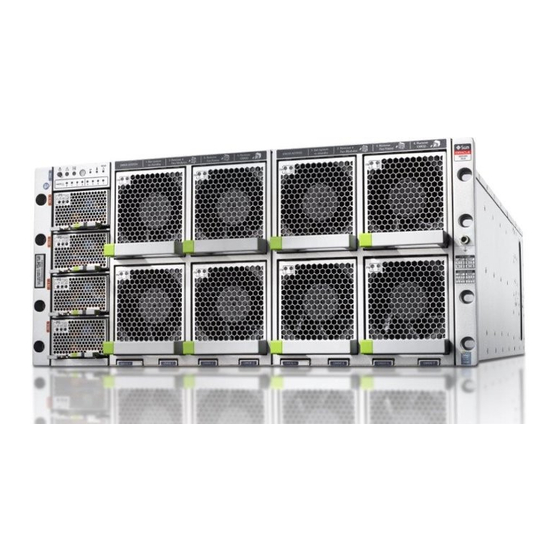
- Page 25 CPU Module (CMOD) Overview The following illustration shows a server with an eight (full) CMOD configuration. Call out 1 identifies the group of four CMODs installed on the left side of the server, and call out 2 identifies the second group of four CMODs installed on the right side of the server. Server and Components Overview...
-
Page 26: Cmod Population Rules
DPCCs 4-7 are not powered and not active. CMOD Population Rules The Oracle Server X5-8 supports four and eight CMOD configurations. Each CMOD supports a single socket containing a single Intel EX Xeon E7-8895 v3 processor. For the four-socket server configuration: CPU modules (CMODs) must be installed in slots 0-3. -
Page 27: Cmod Layout
CPU Module (CMOD) Overview Both fan frames must be installed. ■ All eight fan modules (FMs) must be installed and all FMs are active. ■ CMOD Layout Each CMOD contains the following components: Heatsink and processor assembly ■ 24 DIMM slots arranged in four groups of six ■... -
Page 28: Cmod And Fan Module Power
This section provides information about the server system module (SMOD) and its components. It includes: “SMOD Overview” on page 29 ■ “Storage Drives” on page 30 ■ “SMOD Motherboard” on page 31 ■ Oracle Server X5-8 Service Manual • December 2015... -
Page 29: Smod Overview
System Module (SMOD) Overview “Service Processor (SP)” on page 31 ■ “Storage Drive Backplanes” on page 32 ■ “SAS Host Bus Adapter (HBA) Card, Riser, and Cables” on page 32 ■ “Internal USB Ports” on page 34 ■ “Energy Storage Module and Cable” on page 34 ■... -
Page 30: Storage Drives
Removal and installation levers (2) SMOD Storage Drives In the following illustration, call out 1 shows the location of the eight storage drive slots, which are arranged in two rows of four each. Oracle Server X5-8 Service Manual • December 2015... -
Page 31: Smod Motherboard
The system Emulex Pilot 3 service processor (SP) is located on the SMOD motherboard and is accessible locally and remotely through management ports on the front of the SMOD. The SP contains Oracle ILOM, an embedded server management tool. The SP is not removable. Server and Components Overview... -
Page 32: Storage Drive Backplanes
SAS Host Bus Adapter (HBA) Card, Riser, and Cables The server requires one internal HBA (Oracle Storage 12 Gb/s RAID HBA, Internal) for the externally-accessible SAS (or SATA) SMOD server storage drives. The HBA is installed in a riser slot on the underside of the SMOD motherboard and is connected to the backplanes by two mini-SAS4I connector cables. - Page 33 System Module (SMOD) Overview Call Out Description SMOD motherboard Cable from HBA to ESM. SAS cables Backplanes Server and Components Overview...
-
Page 34: Internal Usb Ports
Unless you have opted out, port P0 has a factory-installed flash drive that contains Oracle System Assistant, a bootable server set-up, provisioning, and update tool. Port P0 can only be used to support Oracle System Assistant. It cannot be used to boot an OS or store files unrelated to Oracle System Assistant. -
Page 35: Front Indicator Module (Fim) Panel
Server Subsystems “Front Indicator Module (FIM) Panel” on page 35 ■ “Power Supply Unit (PSU) Indicators” on page 36 ■ “Fan Module (FM) Indicators” on page 37 ■ “Storage Drive Unit Indicators” on page 38 ■ “Back Indicator Panel” on page 39 ■... -
Page 36: Power Supply Unit (Psu) Indicators
These light if the corresponding CMOD is in a fault state. required indicators (0- Power Supply Unit (PSU) Indicators Each power supply unit (PSU) has three indicators arranged in a single row from left to right. Oracle Server X5-8 Service Manual • December 2015... -
Page 37: Fan Module (Fm) Indicators
Server Subsystems Call Out Description Description Service Action Required/Locate Lights steady on when the power supply is in a fault (amber) state. Status OK indicator (green) Lights steady on when the PSU is powered on and in a normal functioning state (in this state, the AC indicator is also lit) AC OK indicator (green) Lights steady on when the PSU is connected to a... -
Page 38: Storage Drive Unit Indicators
Storage drives are installed in carriers. Each storage drive carrier has three indicators arranged in a single stacked row and from bottom to top. The following illustration shows the front of the storage drive carrier and the storage drive indicators. Oracle Server X5-8 Service Manual • December 2015... -
Page 39: Back Indicator Panel
Server Subsystems Call Out Description Function Ready to Remove indicator (blue) Lights when the storage drive is ready to be removed from the server in response to an action initiated from the server OS. Service Action Required indicator Lights steady on when the drive is in a fault state. (amber) OK indicator (green) Lights when the storage drive is functioning normally and... -
Page 40: Dual Pcie Card Carrier (Dpcc) Indicators
Each DPCC has two indicator panels, one for each PCIe slot inside the server. Each panel contains a green OK indicator, an amber Service Action Required indicator, and a recessed pinhole Attention (ATTN) button. Oracle Server X5-8 Service Manual • December 2015... -
Page 41: Ac Power Inlet Indicators
Server Subsystems Call Out Description Recessed pinhole button Service Action Required/Locator indicator OK indicator AC Power Inlet Indicators Each power inlet on the AC power block at the back of the server has a single green OK indicator that turns on steady only when the power at the connector is sufficient for the power supply unit. -
Page 42: Switches And Buttons
(activating the button requires the use of a stylus). For location information, see “Back Indicator Panel” on page Host pinhole reset button on the back of the server ■ Oracle Server X5-8 Service Manual • December 2015... -
Page 43: Server Management Software
The server System Module (SMOD) includes an Emulex Pilot 3 service processor (SP) that runs Oracle ILOM. Oracle ILOM allows you to manage and monitor the server locally or remotely in full power or standby power modes. Local and remote interface and control... -
Page 44: Oracle System Assistant
Oracle Hardware Management Pack (HMP) provides a family of command-line interface (CLI) tools for managing your servers, and an SNMP monitoring agent. You can use the Oracle Server CLI tools to configure Oracle servers. The CLI tools work ■ with Oracle Solaris, Oracle Linux, Oracle VM, other variants of Linux, and Windows operating systems. -
Page 45: Storage And Io Subsystem
Server Subsystems For more details on Oracle Hardware Management Pack, refer to: http://www.oracle.com/goto/OHMP/docs Storage and IO Subsystem The server storage and input/ouput subsystem consists of the following: 8 or 16 PCIe Gen3 IO slots (up to eight 16-lane + eight 8-lane) ■... - Page 46 In the following illustration, call out 1 shows the location of the dual PCIe card carriers (DPCCs). The eight DPCCs are directly accessible from the back of the server and are located below the SMOD. Each DPCC holds two PCIe cards. Oracle Server X5-8 Service Manual • December 2015...
-
Page 47: Chassis Cooling Subsystem
Server Subsystems For component serviceability, locations, and designations, see “Component Locations, and ■ Designations” on page Chassis Cooling Subsystem System cooling air flows from front to back. Primary cooling is provided by eight redundant front-side accessible 100 watt hot-swappable cooling fan modules. To maintain the integrity of the cooling system, ensure that: All CMOD processors have a heat sink. - Page 48 However, to maintain the integrity of the cooling subsystem, FMs 4-7 must be installed in the server. Call Out Description Zone 0: Power supplies Cooling provided by power supply fans Oracle Server X5-8 Service Manual • December 2015...
- Page 49 Server Subsystems Call Out Description Zone 1: CMODS 0 and 1 Cooling provided by FMs 0 and 1 Zone 2: CMODs 2 and 3 Cooling provided by FMs 2 and 3 Zone 3: CMODs 4 and 5 Cooling provided by FMs 4 and 5 Zone 4: CMODs 6 and 7 Cooling provided by FMs 6 and 7 Cooling Fan Power...
-
Page 50: Power Subsystem
Server Block Diagram The following illustration shows the a block diagram of the server interconnects between the CMODs, the midplane, and the SMOD. It also shows the interconnects between attached and integrated components: Oracle Server X5-8 Service Manual • December 2015... - Page 51 Server Block Diagram Server and Components Overview...
- Page 52 Oracle Server X5-8 Service Manual • December 2015...
-
Page 53: Troubleshooting And Diagnostics
Troubleshooting and Diagnostics This section provides information about troubleshooting hardware component faults for the Oracle Server X5-8. It contains the following topics. Description Link Maintenance-related information and “Troubleshooting Server Hardware Component procedures used to troubleshoot and repair Faults” on page 53 server hardware issues. -
Page 54: Troubleshooting Server Hardware Faults
3. Prepare the server for service using Oracle ILOM. If you have determined that the hardware fault requires service (physical access to the server), use Oracle ILOM to power off the server, activate the Locate LED, and take the server offline. - Page 55 A component designated as a FRU must be replaced by Oracle Service personnel. Contact Oracle Service. 6. Clear the fault in Oracle ILOM. Depending on the component, you might need to clear the fault in Oracle ILOM. Generally, components that have a FRU ID clear the fault automatically. See Also: “Troubleshoot Hardware Faults”...
- Page 56 In the above example, the Status screen shows that the Memory subsystem requires service. This indicates that a hardware component within the subsystem is in a fault state. To identify the component, click on the subsystem name. Oracle Server X5-8 Service Manual • December 2015...
- Page 57 Before going to the server, review the server Product Notes document for information related to the issue or the component. Oracle Server X5-8 Product Notes contains up-to-date information about the server, including hardware-related issues. To prepare the server for service, see “Preparing for Service”...
-
Page 58: Troubleshooting And Diagnostic Information
Troubleshoot Hardware Faults After servicing the component, you might need to clear the fault in Oracle ILOM. Refer Note - the service procedure for the component for more information. Troubleshooting and Diagnostic Information The following table lists diagnostic- and troubleshooting-related procedures and references that can assist you with resolving server issues. - Page 59 Troubleshoot Hardware Faults “PSU Failure” on page 61 ■ “Memory Failure” on page 61 ■ “CPU Failure” on page 61 ■ “Fan Module Failure” on page 61 ■ “SP Failure” on page 61 ■ “Front Panel Lamp Test” on page 62 ■...
- Page 60 Press the button to prove physical presence. Some service procedures require you to prove ■ physical presence by pressing the Locator indicator button. You can turn the Locator indicator off remotely from Oracle ILOM, or by pressing the ■ button.
-
Page 61: Memory Failure
Troubleshoot Hardware Faults For indicator blink rate information, see “Indicator Blink Rates” on page PSU Failure For a server with a PSU in a failed state, the server amber Service Action Required indicators (front and back) and the amber Servic Action Required indicator on the PSU are on steady. The front and back green Power OK indicator and the green SP indicator are on steady. -
Page 62: Indicator Blink Rates
For the steady on state, an indicator is continually on (lit) and does not blink. This indicates a continuing condition, for example, an operational state (green) or a Service Action Required fault state (amber). Oracle Server X5-8 Service Manual • December 2015... - Page 63 Troubleshoot Hardware Faults Steady Off For the steady off state, an indicator is continually off (not lit) and does not blink. This indicates that a system is not operational, for example, no AC power (unlit green Power OK indicator) or a subsystem not in a fault state (unlit amber Service Action Required indicator).
- Page 64 This indicates a system or component in standby mode. For example, a server in standby power mode or a hot spare device waiting to be used (also used with amber indicators to indicate a predicted fault). Oracle Server X5-8 Service Manual • December 2015...
- Page 65 Troubleshoot Hardware Faults Slow Unison Blink Rate For the slow unison blink rate, the indicators on the component blink in unison for half a second during a one second interval (1 Hz). Typically, this is limited to three successive blinks. This confirms the successful insertion of a removable device (for example, a storage drive) into a powered system (confirming the power connection).
- Page 66 1 Hz. This indicates that a component has an incorrect version or mismatch (for example, a power supply with a lower rating than the one specified). The blink rate is also used for an unsupported component, or a component in an unsupported slot. Oracle Server X5-8 Service Manual • December 2015...
- Page 67 Troubleshoot Hardware Faults Feedback Flash The indicator flashes on and off during periods of activity, commensurate with the activity, but the flashing does not exceed the 2 Hz fast blink rate (see, “Fast Blink Rate” on page 64). For example, this blink rate occurs during disk drive read and write activity and communication port transmit and receive activity.
-
Page 68: The Cmod Fault Remind Test Circuit
The server cooling system uses fans to pull cool air in from the server front intake vents and exhaust warm air out the server back panel vents. If the front or back vents are blocked, the Oracle Server X5-8 Service Manual • December 2015... -
Page 69: Troubleshooting Power Issues
Troubleshoot Hardware Faults airflow through the server is disrupted and the cooling system fails to function properly causing the server internal temperature to rise. Action: Inspect the server front and back panel vents for blockage from dust or debris. Additionally, inspect the server interior for improperly installed components or cables that can block the flow of air through the server. -
Page 70: Troubleshooting With Diagnostic Tools
Once you've determined the tool to use, you can access it locally, while at the server, or remotely. Oracle Server X5-8 Service Manual • December 2015... -
Page 71: Diagnostic Tools
“Diagnostic Tool Documentation” on page 72 ■ Diagnostic Tools The diagnostic tools range in complexity from a comprehensive validation test suite (Oracle VTS) to a chronological event log (Oracle ILOM System Log). They include standalone software packages, firmware-based tests, and hardware-based LED indicators. -
Page 72: Diagnostic Tool Documentation
Applications, and Utilities Guide Attaching Devices to the Server The following sections contain procedures for attaching devices to the server. These allow you to access diagnostic tools when troubleshooting and servicing the server: Oracle Server X5-8 Service Manual • December 2015... -
Page 73: Attach Devices To The Server
Configuring Serial Port Sharing By default, the NET MGT serial port connects to the SP console. Using Oracle ILOM, you can configure it to connect to the host console instead. This feature is useful for Windows kernel debugging, as it enables you to view non-ASCII character traffic from the host console. - Page 74 “Assign Serial Port Output Using the Web Interface” on page 74 ■ Assign Serial Port Output Using the CLI Open an SSH session and at the command line log in to the SP Oracle ILOM CLI. Log in as a user with root or administrator privileges. For example: ipadress ssh root@ where ipadress is the IP address of the server SP.
-
Page 75: Ethernet Port Device Naming
The following illustration explains the logical (operating system) and physical (BIOS) naming conventions used for each interface. These naming conventions might vary depending on conventions of your operating system and which devices are installed in the server. Port BIOS Oracle Solaris Linux Windows Net 1 0701 igb 1... -
Page 76: Contacting Support
On the front panel of the server, look at the middle left of the bezel to locate the server's ■ serial number. Locate the yellow Customer Information Sheet (CIS) attached to your server packaging. ■ This sheet includes the serial number. Oracle Server X5-8 Service Manual • December 2015... - Page 77 Getting Help From Oracle System Assistant, see the Summary screen. ■ From Oracle ILOM, enter the show /SYS command or go to the System Information tab in ■ the Oracle ILOM browser interface. Troubleshooting and Diagnostics...
- Page 78 Oracle Server X5-8 Service Manual • December 2015...
-
Page 79: Servicing The Server
Servicing the Server This section provides generalized information about servicing the server. It includes Section Description Link Component serviceability requirements, “Component Locations, and Designations” on page 79 locations and designations Procedures for creating an ESD-safe work “Performing Electrostatic Discharge and Static Prevention space Measures”... -
Page 80: Component Locations
■ disconnected from the power source. A CRU or FRU designation determines who is qualified to service a component. CRUs can be serviced by customers. ■ FRUs must be serviced by qualified Oracle Service personnel. ■ Component Service Designation Serviceability... - Page 81 Component Locations, and Designations Call Out Description Call Out Description † AC power block Midplane ‡ Dual PCIe carrier card (DPCC) with Server chassis PCIe card (8) Host bus adapter (HBA) card CPU module (CMOD) (4 or 8) Energy storage module Fan frame (2) Storage drive (8) Fan module (8)
-
Page 82: Component Designations
Bottom row from left to right: FM 0, FM 2, FM 4, and FM 6. ■ Top row from left to right: FM 1, FM 3, FM 5, and FM 7. ■ Oracle Server X5-8 Service Manual • December 2015... - Page 83 Component Locations, and Designations Call Out Description FM 0 FM 1 FM 2 FM 3 FM 4 FM 5 FM 6 FM 7 The eight fan modules are installed in two fan frames The left frame contains FM 0, FM1, FM2, and FM 3.
- Page 84 The server is available with four CMODs or eight CMODs. Four-CMOD systems have CMODs in CMOD 0–CMOD 3, and filler panels in CMOD 4–CMOD 7. For more information, see “CPU Module (CMOD) Overview” on page Call Out Description CMOD 0 Oracle Server X5-8 Service Manual • December 2015...
- Page 85 Component Locations, and Designations Call Out Description CMOD 1 CMOD 2 CMOD 3 CMOD 4 CMOD 5 CMOD 6 CMOD 7 Memory Slot Designations Each CMOD contains 24 DIMM slots arranged in four groups of six slots. The following illustration shows the groups and their slot designations. Servicing the Server...
- Page 86 Slots are arranged in two stacked rows of four slots and designated from right to left. The top row contains slots 0, 2, 4, and 6. ■ The bottom row contains slots 1, 3, 5, and 7 ■ Oracle Server X5-8 Service Manual • December 2015...
- Page 87 Component Locations, and Designations Call Out Description Slot 0 Slot 1 Slot 2 Slot 3 Slot 4 Slot 5 Slot 6 Slot 7 DPCC and PCIe Card Slot Designations The eight dual PCIe card carrier (DPCC) slots are arranged in a single row at the back of the server.
- Page 88 The four AC power inputs at the back of the server are arranged in a stack. Starting at the bottom, they are designated AC 0, AC 1, AC 2, and AC 3. The designations match the corresponding PSUs. The AC power block is not a removable component. Oracle Server X5-8 Service Manual • December 2015...
-
Page 89: Component Network Access Control (Nac) Names
Component Locations, and Designations The following illustration shows the location and designation of the inlets on the AC power block. Call Out Description AC 0 AC 1 AC 2 AC 3 Component Network Access Control (NAC) Names Name Description /SYS System /SYS/UUID Unique system ID... -
Page 90: Performing Electrostatic Discharge And Static Prevention Measures
In addition to wearing an anti-static wrist strap when handling components, create an ESD-free work place by using an anti-static mat as a work surface and as a place to set ESD-sensitive Oracle Server X5-8 Service Manual • December 2015... -
Page 91: Tools And Equipment
DIMMs, and CPUs. You can use the following items as anti-static mats: Anti-static bag used to wrap a replacement part ■ ESD mat (orderable from Oracle) ■ A disposable ESD mat (shipped with some optional system components) ■... -
Page 92: Clear Hardware Fault Messages
This procedure uses the Oracle ILOM CLI interface. Before You Begin ■ Open an SSH session and at the command line log in to the SP Oracle ILOM CLI. Log in as a user with root or administrator privileges. For example: ipadress ssh root@ where ipadress is the IP address of the server SP. - Page 93 ■ -u uuid – Show fault diagnosis events that match a specific universal unique identifier ■ (uuid). For command specifics, see the Oracle ILOM documentation at: http://www.oracle.com/ goto/ILOM/docs Use fmadm to clear the fault. Clear the fault according to whether you want to use the acquit, repair, replaced, or repaired.
- Page 94 Oracle Server X5-8 Service Manual • December 2015...
-
Page 95: Preparing For Service
“Managing the Locator Indicator” on page 108 server Locator indicator. Prepare the Server for Hot Service The steps in this remote procedure use the Oracle ILOM web interface. However, the Note - procedure can also be performed remotely using the Oracle ILOM CLI interface. For more information, refer to the Oracle ILOM documentation. -
Page 96: Prepare The Server For Warm Service
Prepare the Server for Warm Service Log in to the service processor Oracle ILOM web interface. Direct a web browser to Oracle ILOM using the IP address of the server SP and log in as root or a as user with administrator privileges. See Oracle X5 Series Servers Administration Guide. - Page 97 Log in to the Oracle ILOM web interface. Direct a web browser to Oracle ILOM using the IP address of the server SP and log in as root or a as user with administrator privileges. See “Accessing Oracle ILOM” in Oracle X5 Series Servers Administration Guide.
-
Page 98: Prepare The Server For Cold Service
This procedure uses a combination of the Oracle ILOM web and CLI interfaces. Note - However, the procedure can be performed using only the Oracle ILOM CLI interface (for more information, refer to the Oracle ILOM documentation). Oracle Server X5-8 Service Manual • December 2015... - Page 99 Log in to the Oracle ILOM web interface. Direct a web browser to Oracle ILOM using the IP address of the server SP and log in as root or a as user with administrator privileges. See “Accessing Oracle ILOM” in Oracle X5 Series Servers Administration Guide.
-
Page 100: Powering Off The Server
Powering Off the Server This section contains information and procedures related to power modes and power off options, including complete power removal: “Power Off the Server Using the Server OS” on page 101 ■ Oracle Server X5-8 Service Manual • December 2015... -
Page 101: Power Off The Server Using The Server Os
“Power Off, Immediate (Power Button)” on page 102 ■ “Power Off, Remote (Oracle ILOM CLI)” on page 103 ■ “Power Off, Remote (Oracle ILOM Web Interface)” on page 104 ■ “Remove Power” on page 105 ■ “Power Modes, Shutdowns, and Resets” on page 107 ■... -
Page 102: Power Off, Immediate (Power Button)
(for more information, see “Power Modes, Shutdowns, and Resets” on page 107). Data loss. All applications and files close abruptly without saving. Warn users and Caution - close all applications before powering off. Oracle Server X5-8 Service Manual • December 2015... -
Page 103: Power Off, Remote (Oracle Ilom Cli)
“Power Modes, Shutdowns, and Resets” on page 107 Before You Begin Open an SSH session and at the command line log in to the SP Oracle ILOM CLI. Log in as a user with root or administrator privileges. For example:... -
Page 104: Power Off, Remote (Oracle Ilom Web Interface)
■ http://www.oracle. com/goto/ILOM/docs Power Off, Remote (Oracle ILOM Web Interface) You can use the Oracle ILOM web interface to remotely power off the server to standby power mode. See: “Power Modes, Shutdowns, and Resets” on page 107 Before You Begin Log in to the service processor Oracle ILOM web interface. -
Page 105: Remove Power
108. Click OK. “Managing the Locator Indicator” on page 108 Next Steps ■ Oracle Integrated Lights Out Manager Documentation Library at: ■ http://www.oracle.com/goto/ILOM/docs Remove Power Powering the server from full power mode to standby power mode does not completely remove power from the server. - Page 106 If you are performing a cold reset, wait at least 60 seconds before connecting the AC power cables to the power supplies. For information about cold resets, see “Cold Reset” on page 108. Oracle Server X5-8 Service Manual • December 2015...
-
Page 107: Power Modes, Shutdowns, And Resets
This is the safest method of shutting down the server. To perform a graceful shutdown use the server OS, Oracle ILOM, or the server front panel Power button. -
Page 108: Managing The Locator Indicator
For example, a warm reset might be required after a software or firmware update or when you want to launch Oracle System Assistant or the BIOS Setup Utility. -
Page 109: Turn On The Locator Indicator Remotely (Oracle Ilom Cli)
Before going to the server, you can activate the server Locator indicator to help you identify the server in the rack. Open an SSH session and at the command line log in to the SP Oracle ILOM CLI. Log in as a user with root or administrator privileges. For example:... -
Page 110: Turn On The Locator Indicator Remotely (Oracle Ilom Web Interface)
Turn On the Locator Indicator Remotely (Oracle ILOM Web Interface) Turn On the Locator Indicator Remotely (Oracle ILOM Web Interface) Before going to the server, you can activate the server Locator indicator to help you identify the server in the rack. - Page 111 To turn off the blinking Locator indicator, press the Locator indicator button. To turn on the Locator indicator, press the Locator indicator button. ■ Some Oracle ILOM security procedures require that you turn on the Locator indicator Note - locally, as part of a physical presence verification step.
- Page 112 Oracle Server X5-8 Service Manual • December 2015...
-
Page 113: Servicing Components
Servicing Components This section includes the following removal and installation procedures for customer- replaceable and field-replaceable components in the Oracle Server X5-8: Section Description Link Upgrade server from four to eight CMODs. “Upgrade the Server from Four to Eight CMODs” on page 113 Remove and install fan modules (FMs). - Page 114 Open each new CMOD and ensure that the DIMMs are configured correctly and properly seated in their slots: Component damage. CMOD components are extremely sensitive to electrostatic Caution - discharge. Wear a wrist strap and use an anti-static wrist mat. Oracle Server X5-8 Service Manual • December 2015...
- Page 115 Upgrade the Server from Four to Eight CMODs To remove the CMOD cover, press down on the green release button and slide the cover away from the front of the CMOD. Check that all DIMMs are installed in their slots and the that the DIMM levers are in their fully upright and locked position.
- Page 116 Repeat the above step for the remaining three slots. Install both fan frames. See “Install a Fan Frame” on page 124. Install all eight fan modules. See “Install a Fan Module” on page 120. Oracle Server X5-8 Service Manual • December 2015...
-
Page 117: Servicing Fan Modules And Fan Frames
Servicing Fan Modules and Fan Frames Servicing Fan Modules and Fan Frames This section includes information and procedures for servicing fan modules (FMs) and fan frames: “Remove a Fan Module” on page 117 ■ “Install a Fan Module” on page 120 ■... - Page 118 Remove a Fan Module A fan in a failed state has a lit amber-color Service Action Required indicator. To unlock the fan module, push in the green release button. Oracle Server X5-8 Service Manual • December 2015...
- Page 119 Remove a Fan Module Data Loss. Do not remove more than one fan module from a column while the system Caution - is in full power mode. This action removes power from the CMODs and causes an immediate shutdown. On an eight-CMOD system, this applies to all fan modules. On a four-CMOD system, this applies to the fan modules in the left-hand fan frame.
-
Page 120: Install A Fan Module
Install a Fan Module Access this component directly from the front of the server. Use this procedure to install a replacement fan module or to install a fan module after accessing the CMODs behind it. Oracle Server X5-8 Service Manual • December 2015... - Page 121 Install a Fan Module For component serviceability, locations, and designations, see “Component Locations, and Before You Begin ■ Designations” on page Align the fan module with the slot. Ensure the handle is positioned at the bottom of the slot with the green release button to the left and that the air vane for the slot swings freely.
-
Page 122: Remove A Fan Frame
Prepare the server for cold or warm service. See “Prepare the Server for Cold Service” on page 98 “Prepare the Server for Warm Service” on page Remove the fans associated with the fan frame. Oracle Server X5-8 Service Manual • December 2015... - Page 123 Remove a Fan Frame The center of the fan frame is marked with green labels. The labels indicate where to Note - hold the frame when you want to install or remove it. Servicing Components...
-
Page 124: Install A Fan Frame
CMOD configured server. For component serviceability, locations, and designations, see “Component Locations, and Before You Begin ■ Designations” on page Oracle Server X5-8 Service Manual • December 2015... - Page 125 Install a Fan Frame For removal instructions, see “Remove a Fan Frame” on page 122. ■ Position the fan frame at the opening in the front of the server with the air vane hinges at the top. The center of the fan frame is marked with green labels. The labels indicate where to Note - grab the frame when you want to install or remove it.
-
Page 126: Servicing Power Supply Units (Psus)
Identify the power supply by its position and designation or, if it has failed, by its steady on Service Action Required indicator. A power supply in a fault state has a lit amber-color Service Action Required indicator. Oracle Server X5-8 Service Manual • December 2015... - Page 127 Remove a PSU To access, the FIM release latch, you need to remove the topmost PSU. Note - To unlock the power supply lever, squeeze together the two green release latches at the end of the lever. Servicing Components...
- Page 128 The pawl at the hinged end of the lever engages the sidewall of the server and provides the pivot point for leverage to disengage the power supply. This action leaves the power supply extending partially from its slot. Oracle Server X5-8 Service Manual • December 2015...
-
Page 129: Install A Psu
Install a PSU To remove the power supply, use two hands to slowly slide it completely out of the server. “Install a PSU” on page 129 See Also ■ “Returning the Server to Operation” on page 235 ■ Install a PSU Access this component directly from the front of the server. - Page 130 The pawl at the hinged end of the lever engages the sidewall of the server and provides the pivot point for the leverage necessary to draw the power supply into the slot and engage the internal connector. Oracle Server X5-8 Service Manual • December 2015...
- Page 131 Install a PSU Pinch point. Keep your fingers clear of the backside of the lever. Caution - Verify that the green Power OK indicator on the power supply indicator panel turns on steady and that the amber Service Action Required indicator is not lit. Servicing Components...
-
Page 132: Servicing The Front Indicator Module (Fim)
Servicing the Front Indicator Module (FIM) This section includes information and procedures for servicing the server front indicator module (FIM): “Remove the FIM” on page 133 ■ “Install the FIM” on page 134 ■ Oracle Server X5-8 Service Manual • December 2015... -
Page 133: Remove The Fim
Remove the FIM Remove the FIM Access this component directly from the front of the server. Remove the FIM when you need to replace it. For component serviceability, locations, and designations, see “Component Locations, and ■ Before You Begin Designations” on page Prepare the server for cold service. -
Page 134: Install The Fim
Access this component directly from the front of the server. For component serviceability, locations, and designations, see “Component Locations, and Before You Begin ■ Designations” on page Position the connector end of the FIM at the opening of the slot. Oracle Server X5-8 Service Manual • December 2015... - Page 135 Install the FIM Ensure that the open side (internal ribbon cable visible) of the FIM is facing upward. To install the FIM, slide it into the slot until it locks and is flush with the front of the server. Servicing Components...
-
Page 136: Servicing The Cpu Module (Cmod) Components
“Remove a CMOD” on page 137 ■ “Remove and Install the CMOD Cover” on page 140 ■ “Install a CMOD” on page 143 ■ “Replace a Failed DIMM” on page 146 ■ Oracle Server X5-8 Service Manual • December 2015... -
Page 137: Remove A Cmod
Remove a CMOD “Install a DIMM” on page 152 ■ “Remove a DIMM” on page 155 ■ “Memory and DIMM Reference” on page 158 ■ “Remove a Heatsink and Processor (FRU)” on page 161 ■ “Install a Heatsink and Processor (FRU)” on page 172 ■... - Page 138 CMOD. Pinch point. Keep your fingers clear of the underside of the lever. Caution - The lever disconnects the CMOD from the midplane and its DPCC. Oracle Server X5-8 Service Manual • December 2015...
- Page 139 Remove a CMOD Use the lever to slide the CMOD partially out of the server until you can grab it with both hands. Servicing Components...
-
Page 140: Remove And Install The Cmod Cover
When removing or installing the CMOD cover, always maintain component serviceability requirements with regard to static protection. To protect components from damage, always use an anti static mat and wrist strap. “Remove a CMOD” on page 137 Before You Begin ■ Oracle Server X5-8 Service Manual • December 2015... - Page 141 Remove and Install the CMOD Cover To remove the CMOD top cover, push the release button, slide the CMOD cover toward the back of the CMOD, and lift it away. Servicing Components...
- Page 142 Remove and Install the CMOD Cover Component damage. CMOD components are extremely sensitive to electrostatic Caution - discharge. Wear a wrist strap and use an anti-static wrist mat. Oracle Server X5-8 Service Manual • December 2015...
-
Page 143: Install A Cmod
Install a CMOD To install the cover, position it over the CMOD chassis with the green button at the front. Set the cover on the chassis, leaving a gap of approximately one inch (25 mm) between the lead edge of the cover and the front of the CMOD. Ensure that the edges of the cover encapsulate the edges of the chassis, and that the pins in the cover are aligned with the slots in the chassis sidewall. - Page 144 Ensure that the CMOD lever is in the fully-open position. Squeeze together the green tabs on the end of the lever. Rotate the lever downward and away from the CMOD. Position the CMOD in the slot. Oracle Server X5-8 Service Manual • December 2015...
- Page 145 Install a CMOD On the front-facing side, ensure that the hinge for the lever is at the bottom. Slide the CMOD into the slot until it stops. In this position, the pawl at the lever hinge is aligned with the slot in the server. To install the CMOD, rotate the lever upward until it locks into place and is flush with the front of the CMOD.
-
Page 146: Replace A Failed Dimm
This procedure uses the DIMM fault remind test circuit in the CMOD to identify the failed DIMM. The circuit is a charged, time-limited circuit. Once power is removed from the server you have 10 minutes to use the circuit. Oracle Server X5-8 Service Manual • December 2015... - Page 147 For component serviceability, locations, and designations, see “Component Locations, and Before You Begin ■ Designations” on page Use Oracle ILOM to identify the location of the failed DIMM and obtain CMOD ■ designation information. For an overview video about replacing a failed DIMM, see Replacing DIMMs.
- Page 148 Replace a Failed DIMM “Remove and Install the CMOD Cover” on page 140. Oracle Server X5-8 Service Manual • December 2015...
- Page 149 Replace a Failed DIMM To locate the failed DIMM, press and hold the Fault Remind button [1]. Call Out Description Fault Remind button Fault Remind Power indicator DIMM slot fault indicator (one for each slot) Verify that the green Fault Remind Power indicator [2] is lit. The Charge Status indicator [2] lights if the Fault Remind circuit is operational.
- Page 150 Remove the DIMM from the CMOD. To align the replacement DIMM in the slot, ensure that the notch on the DIMM connector edge lines up with the key in the DIMM slot. Oracle Server X5-8 Service Manual • December 2015...
- Page 151 Replace a Failed DIMM To install the DIMM in the slot, simultaneously press down on both edges of the DIMM, so the DIMM enters the slot evenly. This action forces the DIMM into the slot and causes the two slot levers to rise and lock the DIMM in the slot.
-
Page 152: Install A Dimm
To remove the CMOD top cover, push the release button, slide the CMOD cover toward the back of the CMOD, and lift it away. “Remove and Install the CMOD Cover” on page 140. Oracle Server X5-8 Service Manual • December 2015... - Page 153 Install a DIMM Component damage. CMOD components are extremely sensitive to electrostatic Caution - discharge. Wear a wrist strap and use an anti-static wrist mat. Locate the DIMM slot. To align the DIMM in the slot, ensure that the notch on the DIMM connector lines up with the key in the DIMM slot.
- Page 154 Verify that the DIMM sits evenly in the slot and is locked. Both levers should be in their fully closed and vertical position. In this position the levers lock the DIMM in the slot. Oracle Server X5-8 Service Manual • December 2015...
-
Page 155: Remove A Dimm
Remove a DIMM Install the CMOD cover. See “Remove and Install the CMOD Cover” on page 140. “Install a CMOD” on page 143 Next Steps ■ Remove a DIMM Use this procedure to remove DIMMs for a memory upgrade or a configuration change or when you need to physically reset a DIMM in its slot (removal and installation). - Page 156 Remove a DIMM “Remove and Install the CMOD Cover” on page 140. Oracle Server X5-8 Service Manual • December 2015...
- Page 157 Remove a DIMM Component damage. CMOD components are extremely sensitive to electrostatic Caution - discharge. Wear a wrist strap and use an anti-static wrist mat. Servicing Components...
-
Page 158: Memory And Dimm Reference
Each CMOD contains 24 DIMM slots arranged in four groups of six slots. Each group of slots is controlled by one of the four memory buffers. Each buffer has two independent memory channels, A and B (eight memory channels per CMOD). Each channel supports 1-3 DIMMs Oracle Server X5-8 Service Manual • December 2015... - Page 159 Remove a DIMM and has three assigned DIMM slots. The following illustration shows the location of the memory buffers, the groups of DIMM slots, and the slots assigned to each channel. Call Out Description Memory buffers DIMM slots assigned to channel A DIMM slots assigned to channel B DIMM Slot Numbering and Color Coding For slot numbering information see...
- Page 160 CMOD 0 and repeat the sequence adding the next set of eight to each CMOD. For example: CMOD 0 gets the initial eight DIMMs, followed by CMOD 1 with the next eight DIMMs, continuing with all CMODs in the configuration. When 32 DIMMs (4- Oracle Server X5-8 Service Manual • December 2015...
-
Page 161: Remove A Heatsink And Processor (Fru)
3. Populate the white slot, white lever slots: D2, D5, D8, D11, D14, D17, D20, D23 Remove a Heatsink and Processor (FRU) Heatsinks and processors are field-replaceable units (FRUs) and must be serviced by an Oracle Service person. This procedure uses the CPU fault remind test circuit. The circuit is a charged, time-limited circuit. - Page 162 CMOD, either by disconnecting power from the server, or by removing the CMOD from the chassis. When you press the Fault Remind button, the Charge Status indicator lights if there is enough power to use the fault remind circuit. Otherwise it remains dark. Oracle Server X5-8 Service Manual • December 2015...
- Page 163 Remove a Heatsink and Processor (FRU) The amber Processor Fault indicator [3] lights if the processor has failed. ■ Call Out Description Fault Remind button Fault Remind Power indicator DIMM slot fault indicator (one for each slot) Servicing Components...
- Page 164 A thermal compound that has been applied to the top of the CPU to facilitate the transfer of heat to the heatsink also acts as an adhesive. To separate the heatsink from the top of the processor, gently twist the heatsink left and right while pulling it upward. Oracle Server X5-8 Service Manual • December 2015...
- Page 165 Remove a Heatsink and Processor (FRU) The twisting action helps to break the seal created by the thermal compound. Remove the heatsink from the CMOD, taking care that you do not allow the thermal compound to contaminate other components. Servicing Components...
- Page 166 Open the spring-loaded CPU load plate release levers by pushing them down and moving them slightly toward the CPU socket and away from their retaining clips Oracle Server X5-8 Service Manual • December 2015...
- Page 167 Remove a Heatsink and Processor (FRU) The levers are numbered. Open lever number 1 first, and then open lever number 2. Rotate the levers to their fully-open position. Servicing Components...
- Page 168 Remove a Heatsink and Processor (FRU) When the second lever is in its fully-open position, the load plate is unlocked and can be opened. To open the load plate, lift the unhinged end to its fully-open position. Oracle Server X5-8 Service Manual • December 2015...
- Page 169 Remove a Heatsink and Processor (FRU) Component damage. The pins of the CPU socket can be easily damaged. Do not Caution - remove the CPU using your fingers. To remove the CPU, use the CPU replacement tool. To remove the CPU, use the CPU replacement tool: Ensure that you use the correct CPU replacement tool.
- Page 170 Lower the tool onto the CPU, ensuring that it sits evenly on the CPU. Push the release tab away from the center button. This action is accompanied by a click sound as the tool closes and grabs the CPU. Oracle Server X5-8 Service Manual • December 2015...
- Page 171 Remove a Heatsink and Processor (FRU) To remove the CPU, lift the tool upward and out of the server. Turn the tool over, so the metal CPU contacts are facing upward and the topside of the tool is facing downward. Hold the CPU by its edges.
-
Page 172: Install A Heatsink And Processor (Fru)
“Remove a Heatsink and Processor (FRU)” on page 161. Before You Begin ■ For component serviceability, locations, and designations, see “Component Locations, and ■ Designations” on page This procedure requires a Phillips screwdriver and an anti-static wrist strap. ■ Oracle Server X5-8 Service Manual • December 2015... - Page 173 Install a Heatsink and Processor (FRU) At the CPU socket, ensure that the CPU load plate and both load plate release levers are in their fully open position. To install a CPU, use the CPU replacement tool. Ensure that you use CPU replacement tool, part number 7080240. The part number is Note - printed on the side of the tool.
- Page 174 Orient the tool so that the triangle on the tool aligns with the triangle on the socket. Lower the tool onto the socket, ensuring that the CPU is correctly positioned and sits flat and evenly in the socket. Oracle Server X5-8 Service Manual • December 2015...
- Page 175 Install a Heatsink and Processor (FRU) When the CPU is correctly positioned, there is no side-to-side movement of the CPU within the socket. To release the CPU from the tool, press the center button. This action is accompanied by a click sound as the tool opens and releases the CPU. Remove the tool.
- Page 176 Lower and lock the right side lever, ensuring that the lever is secured under its retaining clip and that the bend in the lever locks the cover plate. The right side lever must be closed first. Oracle Server X5-8 Service Manual • December 2015...
- Page 177 Install a Heatsink and Processor (FRU) Lower and lock the left side load plate lever, ensuring that it is secured under its retaining clip. To apply the thermal compound, dispense the contents of the syringe as a single dollop in the center on the top of the CPU. Do not spread the thermal compound.
- Page 178 Align the captive spring-loaded heatsink screws with the threaded standoffs on the motherboard. Set the heatsink on top of the CPU. Once the heatsink is in contact with the CPU, avoid extra movement of the heatsink. Oracle Server X5-8 Service Manual • December 2015...
- Page 179 Install a Heatsink and Processor (FRU) Use a number 2 Phillips screwdriver and alternately tighten each screw one- half turn until both screws are completely tightened. Ensure that all tools and debris are removed from the CMOD. Install the CMOD cover. See “Remove and Install the CMOD Cover”...
-
Page 180: Servicing Storage Drives
■ Remove a Storage Drive Access this component directly from the rear of the server. For component serviceability, locations, and designations, see “Component Locations, and Before You Begin ■ Designations” on page Oracle Server X5-8 Service Manual • December 2015... - Page 181 Remove a Storage Drive For storage drive information, see “Storage Drive Reference” on page 184. ■ Prepare the server for hot service. See “Prepare the Server for Hot Service” on page Alternatively, to prepare the server for cold service, see “Prepare the Server for Cold Service”...
-
Page 182: Install A Storage Drive
■ Install a Storage Drive Access this component directly from the front of the server. For component serviceability, locations, and designations, see “Component Locations, and Before You Begin ■ Designations” on page Oracle Server X5-8 Service Manual • December 2015... - Page 183 Install a Storage Drive For storage drive information, see “Storage Drive Reference” on page 184. ■ Prepare the server for hot service. See “Prepare the Server for Hot Service” on page Alternatively, to prepare the server for cold service, see “Prepare the Server for Cold Service”...
-
Page 184: Storage Drive Reference
The drive is flush with the front of the SMOD. “Returning the Server to Operation” on page 235. ■ See Also Storage Drive Reference This section contains storage drive reference information, including storage drive slot population rules. Oracle Server X5-8 Service Manual • December 2015... -
Page 185: Servicing Pcie Cards And The Dual Pcie Card Carriers (Dpccs)
Servicing PCIe Cards and the Dual PCIe Card Carriers (DPCCs) Storage Drive Population Rules When populating the storage drive slots, use the following rules: 1. Every slot in the storage drive bay must contain either a storage drive or a drive filler panel. 2. - Page 186 The ATTN buttons alert the system to a request to remove a PCIe card. When the system has acknowledged the request, it takes the device offline and lights both indicators for each slot. When the indicators are lit, it is safe to remove the component. Oracle Server X5-8 Service Manual • December 2015...
- Page 187 Remove a DPCC To unlock the DPCC lever, lift the release latch and pull the lever downward, away from the server. This action disengages the PCIe card IO connectors from the connectors on the back of the CMODs. Servicing Components...
-
Page 188: Remove A Pcie Card
For component serviceability, locations, and designations, see “Component Locations, and Before You Begin ■ Designations” on page Prepare the server for hot service. See “Prepare the Server for Hot Service” on page Oracle Server X5-8 Service Manual • December 2015... - Page 189 Remove a PCIe Card Alternatively, to prepare the server for cold service, see “Prepare the Server for Cold Service” on page Identify the DPCC containing the PCIe card. Remove the DPCC. See “Remove a DPCC” on page 185. Orient the DPCC so that the hinge is to the left. To open the top of the DPCC, lift the release latch at the non-hinged end of the lid and rotate the lid upward and to the left.
-
Page 190: Install A Pcie Card
Carrier (DPCC). Perform this procedure when replacing a PCIe card or when changing its configuration. For component serviceability, locations, and designations, see “Component Locations, and Before You Begin ■ Designations” on page Oracle Server X5-8 Service Manual • December 2015... - Page 191 Install a PCIe Card Prepare the server for hot service. See “Prepare the Server for Hot Service” on page Alternatively, to prepare the server for cold service, see “Prepare the Server for Cold Service” on page Identify the DPCC PCIe slot. If necessary, remove the DPCC.
- Page 192 To close the top of the DPCC, rotate it to the right ensuring the clip on the edge of the top is secured over the unhinged edge of the DPCC. Oracle Server X5-8 Service Manual • December 2015...
-
Page 193: Install A Dpcc
Install a DPCC Pinch point. Keep fingers away from the underside of the top when closing it. Caution - Clear any related component faults. For more information see “Clear Hardware Fault Messages” on page “Install a DPCC” on page 193 ■... - Page 194 DPCC inward beyond this point. Rotate the lever on the DPCC upward until it locks into place. Pinch point. Keep fingers away from the backside of the lever when closing it. Caution - Oracle Server X5-8 Service Manual • December 2015...
- Page 195 Install a DPCC This action draws the DPCC inward engaging the connectors in the DPCC with the connectors on the server midplane. Use a stylus to press both ATTN buttons on the front of the DPCC. If only a single PCIe card is present, press only the corresponding ATTN button. If you Note - are doing cold service, this step is not necessary.
-
Page 196: Replace A Dpcc
The server contains eight hot-service PCIe Gen 3 DPCCs. Each DPCC has two low-profile PCIe Gen 3 slots, an 8-lane slot and a 16-lane slot. Each DPCC can contain up to two PCIe cards. Oracle Server X5-8 Service Manual • December 2015... -
Page 197: Servicing System Module (Smod) Components
Servicing System Module (SMOD) Components DPCCs connect directly to connectors on the back of the CMODs, so DPCCs and CMODs have a one-to-one relationship with one another. In a four CMOD-configured server, the first four slots (right to left from the back of the server), are active. In an eight CMOD-configured server, all eight slots are active. - Page 198 Obtain labels and a pen for labeling cables. ■ Prepare the server for cold service. See “Prepare the Server for Cold Service” on page Label and disconnect all cables from the SMOD. Disengage the SMOD from the server midplane. Oracle Server X5-8 Service Manual • December 2015...
- Page 199 Remove the SMOD To unlock the SMOD handles, squeeze together the release latches on the end of both handles. To disengage the SMOD from the server midplane, simultaneously, rotate both handles downward to their fully-open position. This action disengages the connectors on the SMOD from the connectors on the server midplane.
-
Page 200: Install The Smod
For component serviceability, locations, and designations, see “Component Locations, and Before You Begin ■ Designations” on page “Remove the SMOD” on page 197. ■ Ensure that the handles on the SMOD are in their fully open position. Oracle Server X5-8 Service Manual • December 2015... - Page 201 Install the SMOD To unlock the SMOD handles, squeeze together the release latches on the end of both handles. To open, rotate both handles downward to their fully-open position. Orient the SMOD with the handles facing away from the server and the connectors facing toward the open slot in the server.
-
Page 202: Servicing The Host Bus Adapter (Hba) Card
This section contains procedures for servicing the HBA card that is located inside the system module (SMOD): “Remove the HBA Card” on page 203 ■ “Install the HBA Card” on page 206 ■ Oracle Server X5-8 Service Manual • December 2015... - Page 203 Remove the HBA Card Remove the HBA Card This is an internal component that is accessible from the rear of the server by removing the SMOD. The host bus adapter (HBA) card is installed in an internal PCIe slot mounted on the SMOD motherboard.
- Page 204 Remove the HBA Card Disconnect the ESM extension cable from the HBA [1]. To unlock the HBA card, rotate the green release handle outward and then downward [2]. Oracle Server X5-8 Service Manual • December 2015...
- Page 205 Remove the HBA Card The handle is on the right (vertical) side of the SMOD. To access it, you might need to push it outward from the inside. To disconnect the HBA card from its connector on the SMOD motherboard, pull the card toward you [1] just far enough so that you can access the SAS cables.
- Page 206 Install the HBA Card The host bus adapter (HBA) card is installed in an internal PCIe slot on the SMOD motherboard. “Remove the HBA Card” on page 203 Before You Begin ■ Oracle Server X5-8 Service Manual • December 2015...
- Page 207 Install the HBA Card For component serviceability, locations, and designations, see “Component Locations, and ■ Designations” on page Position the HBA card with the component side facing upward and the edge connector pointed away from you. With the SMOD positioned upside down and the back (connector) side facing you, align the HBA card with the opening on the right.
- Page 208 Install the storage drives. See “Install a Storage Drive” on page 182. Clear any related component faults. For more information see “Clear Hardware Fault Messages” on page “Install the SMOD” on page 200 Next Steps ■ Oracle Server X5-8 Service Manual • December 2015...
-
Page 209: Servicing The Energy Storage Module And Cables
Replace the Energy Storage Module Servicing the Energy Storage Module and Cables This topic provides instructions for servicing the Energy Storage Module (ESM) and cable. The ESM provides emergency power for the SAS drives. Replace the Energy Storage Module The Energy Storage Module (ESM) sits in a bracket on the top of the SMOD, between the two disk enclosures. - Page 210 Remove the ESM [2] by lifting it out of position. Lift it straight up and out of position. Insert the new ESM into the holder so that the cable extends out the top. Oracle Server X5-8 Service Manual • December 2015...
- Page 211 Replace the ESM Extension Cable Push it straight down into position.. Attach the ESM connector to the ESM extension cable [2]. Replace the ESM Extension Cable Prepare the server for cold service. See “Prepare the Server for Cold Service” on page Remove the SMOD.
- Page 212 Replace the ESM Extension Cable Disconnect the Energy Storage Module (ESM) cable from the ESM extension cable [1]. Slide the cable out of the slot [2]. Turn the SMOD over and locate the HBA. Oracle Server X5-8 Service Manual • December 2015...
- Page 213 Replace the ESM Extension Cable The connector (back) side of the SMOD should still be facing you. DIsconnect the ESM extension cable from the HBA [1]. Disconnect the ESM extension cable from the clips on the enclosure wall [2]. Remove the old ESM extension cable. Route the new ESM extension cable from the HBA, under the support beams, through the clips [2], and through the slot [3].
-
Page 214: Servicing The Sas Cable
This is an internal component that is accessible from the rear of the server by removing the SMOD. Perform this procedure to replace the SAS cables on the SMOD. For component serviceability, locations, and designations, see “Component Locations, and Before You Begin ■ Designations” on page Oracle Server X5-8 Service Manual • December 2015... -
Page 215: Servicing The Internal Usb Flash Drives
Replace the SAS Cable Prepare the server for cold service. See “Prepare the Server for Cold Service” on page Remove the SMOD. See “Remove the SMOD” on page 197. Set the SMOD on a flat surface with the front side facing toward you. Close the SMOD handles. -
Page 216: Remove An Internal Usb Flash Drive
Your server might come equipped with a server-specific version of Oracle System Assistant loaded on a USB flash drive and installed (at the factory) in USB port P0. To use Oracle System Assistant, the flash drive must be installed in port P0, and it must contain only files specific to Oracle System Assistant. - Page 217 Install an Internal USB Drive Oracle System Assistant, if present, is installed in the upper slot (USB port 0) “Install the SMOD” on page 200 Next Steps ■ Install an Internal USB Drive Perform this procedure to access and install internal USB flash drives.This is an internal component accessible from the rear of the server by removing the SMOD.
- Page 218 The USB flash drive ports are located inside the SMOD next to the HBA card. To install the USB drive, insert it into its slot. If you are installing Oracle System Assistant, place it in the upper slot (USB port 0). If you replaced the Oracle System Assistant USB flash drive, reinstall Oracle System Assistant on the new USB flash drive.
-
Page 219: Replace The Real Time Clock (System) Battery
Replace the Real Time Clock (System) Battery For instructions, see the Oracle X5 Series Servers Administration Guide at http://www. oracle.com/goto/x86AdminDiag/docs. “Install the SMOD” on page 200 Next Steps ■ Replace the Real Time Clock (System) Battery Perform this procedure to replace a failed system battery (also known as an RTC battery). - Page 220 Replace the Real Time Clock (System) Battery The system battery is located on the SMOD motherboard. Oracle Server X5-8 Service Manual • December 2015...
- Page 221 Replace the Real Time Clock (System) Battery To remove the battery, pull it up and out of its holder. To orient the replacement battery, ensure that the positive (+) side of the battery is facing away from the holder. To install the battery, set it in the holder and push it inward. The battery snaps into place.
- Page 222 The battery must be square in the holder. If necessary, once the server is operational, access the BIOS Setup Utility to set the Note - clock. “Install the SMOD” on page 200 Next Steps ■ Oracle Server X5-8 Service Manual • December 2015...
-
Page 223: Replace The Midplane Assembly
Replace the Midplane Assembly Replace the Midplane Assembly Hazardous voltage. Possibility of electrical shock if the power cables are connected to Caution - the server when accessing the midplane and bus bar assembly. This is a cold-service procedure. Power down the system and disconnect all power cables before removing the server access panels. - Page 224 Use a lift to remove the server from the rack. The midplane assembly is located inside the server. In the following illustration, call out 1 shows the location of the midplane assembly. Oracle Server X5-8 Service Manual • December 2015...
- Page 225 Replace the Midplane Assembly Loosen the 19 captive screws on the top access panel and remove the panel. Carefully remove and retain the protective black plastic insert that covers the top of the midplane assembly. Note the orientation of the insert with respect to the opening. The insert is fitted to the opening using tabs and flaps.
- Page 226 To remove the midplane assembly, disconnect these connectors. As an aid, a label on the side of the chassis shows the arrangement and labeling of the five connectors. Oracle Server X5-8 Service Manual • December 2015...
- Page 227 Replace the Midplane Assembly The following illustration shows a portion of the label. Reach into the side access opening and disconnect the five connectors from the back of the midplane assembly. To see the connectors, direct the light from a flashlight through the small opening in the Tip - top access just above the cable connect points.
- Page 228 Replace the Midplane Assembly The following illustration shows the location and arrangement of the connectors on the back of the midplane. Oracle Server X5-8 Service Manual • December 2015...
- Page 229 Replace the Midplane Assembly Lift the midplane assembly out of the server chassis from the top access opening. Position the cables so the connectors are hanging outside of the server chassis's side access opening. The cables inside the chassis should lie flat, so they are not damaged during the installation of the replacement midplane assembly.
- Page 230 Ensure that the connectors are positioned correctly, so the key (protrusion) on the side of the connector is aligned with the notch in the connector on the midplane assembly. For best access Oracle Server X5-8 Service Manual • December 2015...
- Page 231 Replace the Midplane Assembly and visibility, first attach the cable labeled PS 0, then PS 2, followed by PS 1, and finally PS 3. Attach the cable for the AC power indicator board last. Position the side access cover at the access opening, ensuring that the four captive screws are aligned with the holes in the side of the chassis.
- Page 232 Install both fan frames. See “Install a Fan Frame” on page 124. Install all eight fan modules. See “Install a Fan Module” on page 120. Install the FIM. See “Install the FIM” on page 134. Oracle Server X5-8 Service Manual • December 2015...
- Page 233 Replace the Midplane Assembly Install the four PSUs. See “Install a PSU” on page 129. At the rear of the server: Install the SMOD. See “Install the SMOD” on page 200. Install all eight DPCCs. See “Install a DPCC” on page 193.
- Page 234 Oracle Server X5-8 Service Manual • December 2015...
-
Page 235: Returning The Server To Operation
Returning the Server to Operation This section describes how to return the server to service after performing cold service. Description Link Steps for returning the server to operation “Prepare the Server for Operation” on page 235 after cold service. Steps for server power-on options. “Power On the Server”... -
Page 236: Power On The Server
Power On the Server After replacing some components, you must clear their fault in Oracle ILOM to clear Note - their fault indicators. For details, see “Clear Hardware Fault Messages” on page 92 Power on the server. “Power On the Server” on page 236 Next Steps ■... -
Page 237: Bios Setup Utility
BIOS Setup Utility This section provides instructions for using the BIOS setup utility, which includes a menu- driven user interface used to change BIOS settings. It includes: “Access the BIOS Setup Utility” on page 237 ■ “BIOS Setup Utility Screens” on page 238 ■... -
Page 238: Bios Setup Utility Screens
Configuration interface for plug-and-play (PnP) devices, virtualization, internal devices,and add-in cards. Boot Configuration interface for boot settings, including boot mode (Legacy or UEFI), Oracle System Assistant Configuration, and boot option priority. Exit Saves or discards changes. This section contains screen captures of BIOS Setup utility screens. To access the BIOS Setup utility, see “Access the BIOS Setup Utility”... - Page 239 BIOS Setup Utility Screens Main Setup Options Options Description Project Version (R/O) BIOS version. This string is a unique identifier used to reference a specific BIOS release. Format is XXYYZZPP, which indicates: XX - Unique project/platform code. YY - BIOS major release. ZZ - BIOS minor release.
-
Page 240: Oracle Server X5-8 Service Manual • December
Shows where DIMM is installed and memory size in gigabytes. Example: Processor 0 DIMMs D0 – 32 GB D1 – 32 GB D2 – 32 GB D3 – 32 GB D4 – 32 GB D5 – 32 GB Oracle Server X5-8 Service Manual • December 2015... - Page 241 BIOS Setup Utility Screens Main Setup Options Options Description D6 – 32 GB D7 – 32 GB D8 – 32 GB D9 – 32 GB D10 – 32 GB D11 – Not present D12 – 32 GB D13 – Not present D14 –...
- Page 242 BIOS Setup Utility Screens Oracle Server X5-8 Service Manual • December 2015...
- Page 243 BIOS Setup Utility Screens BIOS Setup Utility...
-
Page 244: Advanced Screen (Legacy)
BIOS Setup Utility Screens Advanced Screen (Legacy) The following sections show the sub-selections on the Advanced screen. Oracle Server X5-8 Service Manual • December 2015... -
Page 245: Advanced - Processor Configuration
Enabled When enabled, execute disable bit can prevent certain classes of malicious buffer overflow attacks when combined with a supporting OS (Oracle Solaris, Oracle VM, Windows Server, Red Hat Enterprise Linux, SUSE Linux Enterprise Server, and VMware ESXi). Hardware Prefetcher... - Page 246 Rear Port 0 Disabled/ Enabled Enabled Enable or disable rear USB Port 0. Rear Port 1 Disabled/ Enabled Enabled Enable or disable rear USB Port 1. Oracle Server X5-8 Service Manual • December 2015...
- Page 247 Defaults Description Internal Port 0 Disabled/ Enabled Enabled Enable or disable internal USB Port 0. By default, internal port 0 is reserved for Oracle System Assistant. Internal Port 1 Disabled/ Enabled Enabled Enable or disable internal USB Port 1. Serial Port Console...
- Page 248 Active Management Port displayed. (R/O) Refresh Refresh current BMC network information with the latest information from the service processor. Active Management Port NETMGT/ Change the management port that is currently active. NET0/ NET1/ NET2/ Oracle Server X5-8 Service Manual • December 2015...
- Page 249 BIOS Setup Utility Screens Advanced Setup Options Options Defaults Description NET3 Commit Commit the current BMC network information. IPv4 Configuration (R/O) Current configuration of the IPv4 settings. Channel Number (R/O) Current channel number. IPv4 Assignment (R/O) Static/Dynamic Static View whether the service processor is assigned a static IPv4 address or assigned a dynamic IPv4 address using Dynamic Host Control Protocol (DHCP).
- Page 250 Dhcpv6_stateful autoconfiguration is run to learn the IP addresses and DNS information for the device. Static IPv6 Address Set the static IPv6 address. Example: 2001: 0db0:000.82a1:0000:0000:1234:abcd Commit Commit the IPv6 configuration settings. Oracle Server X5-8 Service Manual • December 2015...
- Page 251 BIOS Setup Utility Screens BIOS Setup Utility...
-
Page 252: Advanced - Cpu Power Management Configuration
BIOS Setup Utility Screens Advanced - CPU Power Management Configuration Oracle Server X5-8 Service Manual • December 2015... -
Page 253: Memory Configuration
BIOS Setup Utility Screens Memory Configuration BIOS Setup Utility... -
Page 254: Advanced - Usb Ports
BIOS Setup Utility Screens Advanced - USB Ports Oracle Server X5-8 Service Manual • December 2015... -
Page 255: Advanced - Serial Port Console Redirection
BIOS Setup Utility Screens Advanced - Serial Port Console Redirection BIOS Setup Utility... - Page 256 BIOS Setup Utility Screens Oracle Server X5-8 Service Manual • December 2015...
- Page 257 BIOS Setup Utility Screens BIOS Setup Utility...
- Page 258 BIOS Setup Utility Screens Oracle Server X5-8 Service Manual • December 2015...
-
Page 259: Advanced - Trusted Computing
BIOS Setup Utility Screens Advanced - Trusted Computing BIOS Setup Utility... - Page 260 BIOS Setup Utility Screens Oracle Server X5-8 Service Manual • December 2015...
-
Page 261: Advanced - Network Stack
BIOS Setup Utility Screens Advanced - Network Stack BIOS Setup Utility... -
Page 262: Advanced - Legacy Iscsi
BIOS Setup Utility Screens Advanced - Legacy iSCSI Oracle Server X5-8 Service Manual • December 2015... -
Page 263: Advanced - Bmc Network Configuration
BIOS Setup Utility Screens Advanced - BMC Network Configuration BIOS Setup Utility... - Page 264 BIOS Setup Utility Screens Oracle Server X5-8 Service Manual • December 2015...
- Page 265 BIOS Setup Utility Screens BIOS Setup Utility...
-
Page 266: Io Screen
OS installations. If supported by the hardware and set to enabled, all devices within the system that are SR-IOV capable are configured to support SR-IOV and I/O Oracle Server X5-8 Service Manual • December 2015... - Page 267 BIOS Setup Utility Screens IO Setup Options Options Defaults Description resources are allocated to the device as normal. If set to disabled, I/O resources are not allocated to the device. Disabled/Enabled Disable If Alternate Routing ID (ARI) is supported by the hardware and set to enabled, devices are permitted to locate virtual functions (VFs) in function numbers 8 to 255 of the captured bus number, instead of normal...
- Page 268 BIOS Setup Utility Screens IO Setup Options Options Defaults Description OpROM Enable Disabled/Enabled Enabled Enable or disable Option ROM for the internal host bus adapter (HBA) card. Oracle Server X5-8 Service Manual • December 2015...
- Page 269 BIOS Setup Utility Screens BIOS Setup Utility...
- Page 270 BIOS Setup Utility Screens Oracle Server X5-8 Service Manual • December 2015...
- Page 271 BIOS Setup Utility Screens BIOS Setup Utility...
-
Page 272: Boot Screens
■ If disabled, the system halts and displays the error message “Network Boot Failed” when all PXE boots failed. ■ If set to Boot List, fail over to the main Boot Options Priority list. Oracle Server X5-8 Service Manual • December 2015... - Page 273 BIOS Setup Utility Screens Option Default Description Persistent Boot Support Disabled Allows devices to maintain a position in the boot priority list even after removal so that, if the device is returned, it is not assigned to a lower priority position. UEFIcfg LateSync Enabled Allows synchronization to occur immediately after a BIOS...
- Page 274 Oracle Server X5-8 Service Manual • December 2015...
-
Page 275: Index
82 diagnosing hardware faults, 58 controlling the Locator indicator, 109, 110 diagnostic tools powering off, 103 Oracle ILOM, 71 cold service, preparing the server, 98 Pc-Check, 71 command-line interface (CLI) See CLI U-Boot, 71 complete power removal, 100, 105, 107... - Page 276 92 Service Action Required Rear front indicator module (FIM) front panel, 35 installing, 134 SMOD, 42 location, 35 removing, 133 back panel, 42 full power mode, 107 front panel, 35 Oracle Server X5-8 Service Manual • December 2015...
- Page 277 CMOD cover, 140 DIMM, 155 DPCC, 185 on-board test circuit, 68 fan frame, 122 Oracle ILOM, 71 fan module, 117 Oracle System Assistant, 34, 44 FIM, 133 overview HBA, 203 back side components, 22 heatsink and processor, 161 chassis, 19...
- Page 278 42 SP reset, 42 warm service, preparing the server, 96 system web interface battery (CR 2032), replacing, 219 controlling the Locator indicator, 110 cooling subsystem, 47 powering off, 104 Oracle Server X5-8 Service Manual • December 2015...
Need help?
Do you have a question about the X5-8 and is the answer not in the manual?
Questions and answers