YASKAWA iQpump1000 User Manual
Ac drive intelligent pump controller
Hide thumbs
Also See for iQpump1000:
- Quick start manual (356 pages) ,
- Installation & start?up manual (114 pages) ,
- Setup procedure (10 pages)
Table of Contents
Advertisement
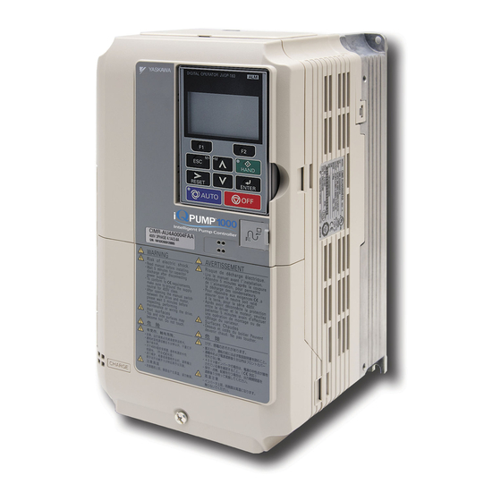
iQpump1000 AC Drive
Intelligent Pump Controller
User Manual
Type: CIMR-PW A
Models: 200 V Class: 3/4 to 175 HP ND
400 V Class: 3/4 to 1000 HP ND
600 V Class: 2 to 250 HP ND
To properly use the product, read this manual thoroughly and retain
for easy reference, inspection, and maintenance. Ensure the end user
receives this manual.
MANUAL NO. TOEP YAIP1W 01F
PUBLISHED MARCH 2017
REVISION <7>
DRIVE SOFTWARE PRG: 8554
1
Receiving
2
Mechanical Installation
3
Electrical Installation
4
Start-Up Programming &
Operation
5
Troubleshooting
6
Periodic Inspection &
Maintenance
7
Peripheral Devices &
Options
A
Specifications
B
Parameter List
C
MEMOBUS/Modbus
Communications
D
Standards Compliance
Advertisement
Chapters
Table of Contents

Related Manuals for YASKAWA iQpump1000


Summary of Contents for YASKAWA iQpump1000
- Page 1 AC Drive Intelligent Pump Controller User Manual Type: CIMR-PW A Models: 200 V Class: 3/4 to 175 HP ND 400 V Class: 3/4 to 1000 HP ND 600 V Class: 2 to 250 HP ND To properly use the product, read this manual thoroughly and retain for easy reference, inspection, and maintenance.
- Page 3 Please read this cheat sheet and other documentation provided with the iQpump thoroughly before attempting any installation. The setup procedure begins on the next page. YASKAWA TOEP YAIP1W 01F YASKAWA AC Drive - iQpump1000 User Manual...
- Page 4 For best performance, the drive input supply voltage must be equal to or greater than the motor rated voltage. Note: Do NOT adjust sec per Open Chassis month. YASKAWA TOEP YAIP1W 01F YASKAWA AC Drive - iQpump1000 User Manual...
- Page 5 YASKAWA TOEP YAIP1W 01F YASKAWA AC Drive - iQpump1000 User Manual...
- Page 6 3 sec. to go back to the main menu. Please refer to the iQpump Quick Start Manual, (Document No. TOEP YAIP 1W 01) on how to access other drive monitors. YASKAWA TOEP YAIP1W 01F YASKAWA AC Drive - iQpump1000 User Manual...
- Page 7 Enables or disables the Hand Key on the digital op- Hand Key on keypad. Hand Key erator. P5-04 Enabled Enable / Disable 0: Disabled (See Step 10) 1: Enabled YASKAWA TOEP YAIP1W 01F YASKAWA AC Drive - iQpump1000 User Manual...
- Page 8 Start / Draw Down Level (P1-04) System Units (P1-02) Start / Draw Down Level (P1-04) (Example PSI) (Example 100.0 PSI) (Example PSI) (Example -50.0 PSI, (150.0 – 50.0) Maximum YASKAWA TOEP YAIP1W 01F YASKAWA AC Drive - iQpump1000 User Manual...
- Page 9 / unmanned areas. Use parameter P4-10 to enable. When the iQpump is powered down while running , an internal run command will automatically be initiated upon power -up. YASKAWA TOEP YAIP1W 01F YASKAWA AC Drive - iQpump1000 User Manual...
- Page 10 Start Pump System System Setpoint WAIT Delay (Example 80 PSI) FEEDBACK SIGNAL LEVEL Refer to Illustration 2 on Page 3 of 4 for additional information on the Start Level Function. YASKAWA TOEP YAIP1W 01F YASKAWA AC Drive - iQpump1000 User Manual...
- Page 11 (P1-06) where it will hold for 5 sec. (P2-03) before going to sleep. Step 5: Run system in normal automatic operation and verify sleep and wake-up operation until system performs satisfactory. YASKAWA TOEP YAIP1W 01F YASKAWA AC Drive - iQpump1000 User Manual...
- Page 12 This Page Intentionally Blank YASKAWA TOEP YAIP1W 01F YASKAWA AC Drive - iQpump1000 User Manual...
- Page 13 Flange Type Models 2A0138, 4A0072, and 5A0041 and 5A0052 .......... 72 Flange Type Models 4A0088 and 4A0103 ................74 Flange Type Models 2A0169 and 2A0211, 4A0139 and 4A0165, and 5A0062 to 5A0099 ..76 YASKAWA TOEP YAIP1W 01F YASKAWA AC Drive - iQpump1000 User Manual...
- Page 14 Wiring the Control Circuit Terminal ....................123 3.9 Control I/O Connections ....................125 Sinking/Sourcing Mode for Digital Inputs ..................125 Terminals A1, A2, and A3 Input Signal Selection................126 Terminal AM/FM Signal Selection ....................129 YASKAWA TOEP YAIP1W 01F YASKAWA AC Drive - iQpump1000 User Manual...
- Page 15 Hybrid Sequence Control ........................ 208 Differential Level Detection ......................209 4.7 Basic iQpump Setup and Application Preset Parameters..........210 4.8 Test Run with No Load......................246 No-Load Operation Test Run ......................246 YASKAWA TOEP YAIP1W 01F YASKAWA AC Drive - iQpump1000 User Manual...
- Page 16 Three-Phase 600 V Class Drive Models 5A0003 to 5A0032 ............322 Three-Phase 600 V Class Drive Models 5A0041 to 5A0099 ............323 Three-Phase 600 V Class Drive Models 5A0125 to 5A0242 ............324 YASKAWA TOEP YAIP1W 01F YASKAWA AC Drive - iQpump1000 User Manual...
- Page 17 H3: Multi-Function Analog Inputs ....................383 H4: Analog Outputs ......................... 385 H5: MEMOBUS/Modbus Serial Communication ................386 H6: Pulse Train Input........................387 B.9 L: Protection Function ......................388 L1: Motor Protection ........................388 YASKAWA TOEP YAIP1W 01F YASKAWA AC Drive - iQpump1000 User Manual...
- Page 18 U3: Fault History..........................442 U4: Maintenance Monitors ......................443 U5: PID Monitors ..........................446 U6: Operation Status Monitors ......................447 U7: CASE Monitors ......................... 447 U9: Operation Status Monitors ......................447 YASKAWA TOEP YAIP1W 01F YASKAWA AC Drive - iQpump1000 User Manual...
- Page 19 D.2 UL and CSA Standards .....................496 UL Standards Compliance ......................496 CSA Standards Compliance......................503 Drive Motor Overload Protection ..................... 503 Precautionary Notes on External Heatsink (IP00/Open Type Enclosure) ........504 YASKAWA TOEP YAIP1W 01F YASKAWA AC Drive - iQpump1000 User Manual...
- Page 20 Table of Contents This Page Intentionally Blank YASKAWA TOEP YAIP1W 01F YASKAWA AC Drive - iQpump1000 User Manual...
- Page 21 Preface & General Safety This section provides safety messages pertinent to this product that, if not heeded, may result in fatality, personal injury, or equipment damage. Yaskawa is not responsible for the consequences of ignoring these instructions. PREFACE.......................22 GENERAL SAFETY....................24...
- Page 22 Yaskawa must be supplied to the end user with appropriate warnings and instructions as to the safe use and operation of that part. Any warnings provided by Yaskawa must be promptly provided to the end user.
- Page 23 • PROFIBUS-DP is a trademark of PROFIBUS International (PI). • PROFNET is a trademark of PROFIBUS International (PI). • Other companies and product names mentioned in this manual are trademarks of those companies. YASKAWA TOEP YAIP1W 01F YASKAWA AC Drive - iQpump1000 User Manual...
- Page 24 • When ordering a new copy of the manual due to damage or loss, contact your Yaskawa representative or the nearest Yaskawa sales office and provide the manual number shown on the front cover.
- Page 25 Do not attempt to modify or alter the drive in any way not explained in this manual. Failure to comply could result in death or serious injury. Yaskawa is not responsible for any modification of the product made by the user. This product must not be modified. Do not allow unqualified personnel to use equipment.
- Page 26 Use an AC reactor or DC link choke in the following situations: • to suppress harmonic current. • to smooth peak current that results from capacitor switching. • when the power supply is above 600 kVA. YASKAWA TOEP YAIP1W 01F YASKAWA AC Drive - iQpump1000 User Manual...
- Page 27 Yaskawa offers protective designs for drives that must be used in areas subjected to oil mist and excessive vibration. Contact Yaskawa or your Yaskawa agent for details.
- Page 28 Wiring Yaskawa recommends using ring terminals on all drive models. Drive models 2A0069 to 2A0415, 4A0058 to 4A1200, and 5A0041 to 5A0242 require the use of use ring terminals for UL/cUL compliance. Use only the tools recommended by the terminal manufacturer for crimping.
- Page 29 Make sure that lubrication is sufficient within the entire speed range to avoid machine damage. Note that operation above the rated speed can increase the noise generated by the machine. YASKAWA TOEP YAIP1W 01F YASKAWA AC Drive - iQpump1000 User Manual...
- Page 30 Customers who intend to use the product described in this manual for devices or systems relating to transportation, health care, space aviation, atomic power, electric power, or in underwater applications must first contact their Yaskawa representatives or the nearest Yaskawa sales office.
- Page 31 Receiving This chapter explains how to inspect the drive upon receipt, and gives an overview of the different enclosure types and components. MODEL NUMBER AND NAMEPLATE CHECK............32 YASKAWA TOEP YAIP1W 01F YASKAWA AC Drive - iQpump1000 User Manual...
- Page 32 B – Software version F – Output specifications C – Enclosure type G – Input specifications D – Serial number H – AC drive model Figure 1.1 Nameplate Information Example YASKAWA TOEP YAIP1W 01F YASKAWA AC Drive - iQpump1000 User Manual...
- Page 33 18.5 (25) 2A0081 22 (30) 2A0110 30 (40) 2A0138 37 (50) 2A0169 45 (60) 2A0211 55 (75) 2A0250 75 (100) 2A0312 90 (125) 2A0360 110 (150) 2A0415 110 (175) YASKAWA TOEP YAIP1W 01F YASKAWA AC Drive - iQpump1000 User Manual...
- Page 34 5A0077 55 (75) 5A0099 75 (100) 5A0125 90 (125) 5A0145 110 (150) 5A0192 160 (200) 5A0242 185 (250) Note: Refer to Single-Phase Derating on page 329 for Single-Phase ratings. YASKAWA TOEP YAIP1W 01F YASKAWA AC Drive - iQpump1000 User Manual...
- Page 35 Mechanical Installation This chapter explains how to properly mount and install the drive. MECHANICAL INSTALLATION................36 FLANGE TYPE ENCLOSURE (NEMA 12 BACKSIDE) DIMENSIONS & HEAT LOSS........................53 YASKAWA TOEP YAIP1W 01F YASKAWA AC Drive - iQpump1000 User Manual...
- Page 36 2.1. Failure to comply may damage the drive due to improper cooling. Figure 2.1 Correct Installation Orientation NOTICE: Install the drive upright as specified in the manual. Failure to comply may damage the drive due to improper cooling. YASKAWA TOEP YAIP1W 01F YASKAWA AC Drive - iQpump1000 User Manual...
- Page 37 Align the tops of the drives when installing drives of different heights in the same enclosure panel. Leave space between the tops and bottoms of stacked drives for easier cooling fan replacement. YASKAWA TOEP YAIP1W 01F YASKAWA AC Drive - iQpump1000 User Manual...
- Page 38 A – No space between drive and C – Space between drive and washer washer D – Spring washer open Figure 2.7 B – Spring washer fully closed Figure 2.5 Spring Washer YASKAWA TOEP YAIP1W 01F YASKAWA AC Drive - iQpump1000 User Manual...
- Page 39 Pass wire through the holes of all four eye bolts. A – Eye bolt C – Suspending angle: 50° or greater B – Wires Figure 2.8 Suspension Wire Angle Example YASKAWA TOEP YAIP1W 01F YASKAWA AC Drive - iQpump1000 User Manual...
- Page 40 The HOA keypad mounts to an enclosure two different ways: • External/face-mount installs the HOA keypad outside the enclosure panel • Internal/flush-mount installs the HOA keypad inside the enclosure panel YASKAWA TOEP YAIP1W 01F YASKAWA AC Drive - iQpump1000 User Manual...
- Page 41 Enclosure panel Figure 2.12 External/Face-Mount Installation Internal/Flush-Mount An internal/flush-mount requires an installation support set that must be purchased separately. Contact Yaskawa to order an installation support set and mounting hardware. Figure 2.13 illustrates how to attach the Installation Support Set A.
- Page 42 Use a gasket between the enclosure panel and the HOA keypad in environments with a significant amount of dust or other airborne debris. 45 (1.77) 59 (2.32) +0.5 (0.02) Unit : mm (in) Figure 2.14 Panel Cut-Out Dimensions (Internal/Flush-Mount Installation) YASKAWA TOEP YAIP1W 01F YASKAWA AC Drive - iQpump1000 User Manual...
- Page 43 UL Type 1 Kit Selection on page 52 to select the appropriate kit. <2> Contact a Yaskawa representative for IP20/NEMA 1, UL Type 1 Kit availability for these models. YASKAWA TOEP YAIP1W 01F YASKAWA AC Drive - iQpump1000 User Manual...
- Page 44 (12.95) (28.74) (11.14) (10.24) (0.31) (21.65) (21.06) (0.30) (7.09) (4.33) (0.09) (0.09) (90.4) 2.286 2A0211F – (12.95) (28.74) (11.14) (10.24) (0.31) (21.65) (21.06) (0.30) (7.09) (4.33) (0.09) (0.09) (92.6) YASKAWA TOEP YAIP1W 01F YASKAWA AC Drive - iQpump1000 User Manual...
- Page 45 (0.18) (0.18) (257.9) <1> Removing the top protective cover from an IP20/NEMA 1, UL Type 1 enclosure drive voids NEMA 1, UL Type 1 protection while retaining IP20 conformity. YASKAWA TOEP YAIP1W 01F YASKAWA AC Drive - iQpump1000 User Manual...
- Page 46 <1> Removing the top protective cover or bottom conduit bracket from an IP20/NEMA 1, UL Type 1 enclosure drive voids NEMA 1, UL Type 1 protection while maintaining IP20 conformity. YASKAWA TOEP YAIP1W 01F YASKAWA AC Drive - iQpump1000 User Manual...
- Page 47 (3.1) 2A0010F – – – – – (1.7) (1.5) (1.5) (1.6) (2.8) (3.1) (0.9) (1.4) 2A0012F – – – – – (1.7) (2.2) (1.5) (1.6) (2.8) (3.1) (0.9) (1.4) YASKAWA TOEP YAIP1W 01F YASKAWA AC Drive - iQpump1000 User Manual...
- Page 48 (2.0) 4A0088F – – – – (3.3) (4.1) (0.9) (3.9) (2.6) (1.0) (2.0) (2.4) (1.1) 4A0103F – – – – (3.3) (4.1) (0.9) (3.9) (2.6) (1.0) (2.0) (2.4) (1.1) YASKAWA TOEP YAIP1W 01F YASKAWA AC Drive - iQpump1000 User Manual...
- Page 49 Removing the top protective cover or bottom conduit bracket from an IP20/NEMA 1, UL Type 1 enclosure drive voids NEMA 1, UL Type 1 protection while maintaining IP20 conformity. YASKAWA TOEP YAIP1W 01F YASKAWA AC Drive - iQpump1000 User Manual...
- Page 50 <1> Customers may convert these models to IP20/NEMA 1, UL Type 1 enclosures using an IP20/NEMA 1, UL Type 1 Kit. Refer to IP20/NEMA 1, UL Type 1 Kit Selection on page 52 to select the appropriate kit. YASKAWA TOEP YAIP1W 01F YASKAWA AC Drive - iQpump1000 User Manual...
- Page 51 <1> Customers may convert these models to IP20/NEMA 1, UL Type 1 enclosures using an IP20/NEMA 1, UL Type 1 Kit. Refer to IP20/NEMA 1, UL Type 1 Kit Selection on page 52 to select the appropriate kit. YASKAWA TOEP YAIP1W 01F YASKAWA AC Drive - iQpump1000 User Manual...
- Page 52 IP20/NEMA 1, UL Type 1 Kit when performing the conversion. Contact a Yaskawa representative for IP20/NEMA 1, UL Type 1 Kit availability for IP00/Open Type models not listed. Table 2.11 IP20/NEMA 1, UL Type 1 Kit Selection...
- Page 53 Loss NOTICE Refer to the iQpump1000 6-Phase/12-Pulse Input Installation Manual TOEPYAIP1W03 for information on 12-pulse Flange and non-Flange models. This manual is posted on the Yaskawa website, www.yaskawa.com. Flange Type Models 2A0004 to 2A0012, 4A0002 to 4A0005, and 5A0003 and 5A0004 Flange Type Exterior and Mounting Dimensions 0.76...
- Page 54 HD (Fc = 8 kHz) Wt. kg (lb) Class Internal External Total Internal External Total 5A0003 23.3 21.5 44.8 19.8 28.9 48.7 3.4 (7.5) 5A0004 33.6 27.5 61.1 27.6 54.3 81.9 3.4 (7.5) YASKAWA TOEP YAIP1W 01F YASKAWA AC Drive - iQpump1000 User Manual...
- Page 55 +/- 0.02 in. [0.5 mm] 2. EXPOSED HEATSINK RECOMMENDED CLEARANCE D=1.97 in. [50 mm] MINUS PANEL THICKNESS Unit: in. [mm] Figure 2.16 Models 2A0004 to 2A0012, 4A0002 to 4A0005, and 5A0003 and 5A0004 YASKAWA TOEP YAIP1W 01F YASKAWA AC Drive - iQpump1000 User Manual...
- Page 56 HORIZONTAL MTG DIM NOTE: Maximum surrounding air temperature is 50 °C [122 °F] Unit: in. [mm] Figure 2.17 Models 2A0018 and 2A0021, 4A0007 to 4A0011, and 5A0006 and 5A0009 YASKAWA TOEP YAIP1W 01F YASKAWA AC Drive - iQpump1000 User Manual...
- Page 57 HD (Fc = 8 kHz) Wt. kg (lb) Class Internal External Total Internal External Total 5A0006 43.7 28.1 71.8 27.0 53.0 80.0 3.7 (8.1) 5A0009 68.9 43.4 112.3 36.4 78.7 115.1 3.7 (8.1) YASKAWA TOEP YAIP1W 01F YASKAWA AC Drive - iQpump1000 User Manual...
- Page 58 +/- 0.02 in. [0.5 mm] 2. EXPOSED HEATSINK RECOMMENDED CLEARANCE Unit: in. [mm] D=2.36 in. MINUS PANEL THICKNESS Figure 2.18 Models 2A0018 and 2A0021, 4A0007 to 4A0011, and 5A0006 and 5A0009 YASKAWA TOEP YAIP1W 01F YASKAWA AC Drive - iQpump1000 User Manual...
- Page 59 HORIZONTAL MTG DIM HORIZONTAL MTG DIM NOTE: Maximum surrounding air temperature is 50 °C [122 °F] Unit: in. [mm] Figure 2.19 Models 2A0030 and 2A0040, 4A0018 and 4A0023, and 5A0011 YASKAWA TOEP YAIP1W 01F YASKAWA AC Drive - iQpump1000 User Manual...
- Page 60 ND (Fc = 2 kHz) HD (Fc = 8 kHz) Wt. kg (lb) Class Internal External Total Internal External Total 5A0011 88.0 56.1 144.1 49.5 110.9 160.4 4.1 (9.0) YASKAWA TOEP YAIP1W 01F YASKAWA AC Drive - iQpump1000 User Manual...
- Page 61 =/- 0.02 in. [0.5 mm] 2. EXPOSED HEATSINK RECOMMENDED CLEARANCE Unit: in. [mm] D=2.36 in. [60 mm] MINUS PANEL THICKNESS Figure 2.20 Models 2A0030 and 2A0040, 4A0018 and 4A0023, and 5A0011 YASKAWA TOEP YAIP1W 01F YASKAWA AC Drive - iQpump1000 User Manual...
- Page 62 5.51 [47] [140.0] NOTE: Maximum surrounding air temperature is 50 °C (122 °F) HORIZONTAL MTG DIM 7.09 [180.0] 6.85 [174] Unit: in. [mm] 9.21 [234.0] Figure 2.21 Model 4A0031 YASKAWA TOEP YAIP1W 01F YASKAWA AC Drive - iQpump1000 User Manual...
- Page 63 [254.0] NOTES: 1. CUTOUT TOLERANCES: +/- 0.02 in. [0.5 mm] 2. EXPOSED HEATSINK RECOMMENDED CLEARANCE Unit: in. [mm] D=1.97 in. [50 mm] MINUS PANEL THICKNESS Figure 2.22 Model 4A0031 YASKAWA TOEP YAIP1W 01F YASKAWA AC Drive - iQpump1000 User Manual...
- Page 64 HORIZONTAL MTG DIM NOTE: Maximum surrounding air temperature is 50 °C (122 °F) 7.09 [180.0] 6.85 Unit: in. [mm] [174] 9.21 [234.0] Figure 2.23 Models 2A0056, 4A0038, and 5A0017 and 5A0022 YASKAWA TOEP YAIP1W 01F YASKAWA AC Drive - iQpump1000 User Manual...
- Page 65 HD (Fc = 8 kHz) Wt. kg (lb) Class Internal External Total Internal External Total 5A0017 146.7 96.6 243.3 67.5 144.7 212.2 6.0 (13.2) 5A0022 178.3 99.4 277.7 81.1 203.8 284.9 6.0 (13.2) YASKAWA TOEP YAIP1W 01F YASKAWA AC Drive - iQpump1000 User Manual...
- Page 66 +/- 0.021 in. [0.5 mm] 2. EXPOSED HEATSINK RECOMMENED CLEARANCE Unit: in. [mm] D=3.5 in. [88.9 mm] MINUS PANEL THICKNESS Figure 2.24 Models 2A0056, 4A0038, and 5A0017 and 5A0022 YASKAWA TOEP YAIP1W 01F YASKAWA AC Drive - iQpump1000 User Manual...
- Page 67 HORIZONTAL MOUNTING DIM NOTE: Maximum surrounding air temperature id 50 °C (122 °F) HORIZONTAL MOUNTING DIM Unit: in. [mm] Figure 2.25 Models 2A0069 and 2A0081, 4A0044, and 5A0027 and 5A0032 YASKAWA TOEP YAIP1W 01F YASKAWA AC Drive - iQpump1000 User Manual...
- Page 68 HD (Fc = 8 kHz) Wt. kg (lb) Class Internal External Total Internal External Total 5A0027 227.2 132.1 359.3 113.9 267.2 381.1 8.7 (19.1) 5A0032 279.9 141.6 421.5 132.2 332.9 465.1 8.7 (19.1) YASKAWA TOEP YAIP1W 01F YASKAWA AC Drive - iQpump1000 User Manual...
- Page 69 +/- 0.02 in. [0.5 mm] 2. EXPOSED HEATSINK RECOMMENDED CLEARANCE Unit: in. [mm] D=3.35 in. [85 mm] MINUS PANEL THICKNESS Figure 2.26 Models 2A0069 and 2A0081, 4A0044, and 5A0027 and 5A0032 YASKAWA TOEP YAIP1W 01F YASKAWA AC Drive - iQpump1000 User Manual...
- Page 70 (2) MOUNTING BRACKETS USED DURING TRANSPORT ONLY REMOVE BEFORE INSTALLING NOTE: Maximum surrounding air temperature is 50 °C (122 °F) Unit: in. [mm] Figure 2.27 Models 2A0110 and 4A0058 YASKAWA TOEP YAIP1W 01F YASKAWA AC Drive - iQpump1000 User Manual...
- Page 71 +/- 0.02 in. [0.5 mm] 2. EXPOSED HEATSINK DEPTH D=3.82 in. [97 mm] MINUS PANEL THICKNESS 3. MINIMUM RECOMMENDED PANEL Unit: in. [mm] THICKNESS: 12 GA Figure 2.28 Models 2A0110 and 4A0058 YASKAWA TOEP YAIP1W 01F YASKAWA AC Drive - iQpump1000 User Manual...
- Page 72 USED DURING TRANSPORT ONLY REMOVE BEFORE INSTALLING NOTE: Maximum surrounding air temperature is 50 °C (122 °F) Unit: in. [mm] Figure 2.29 Models 2A0138, 4A0072, and 5A0041 and 5A0052 YASKAWA TOEP YAIP1W 01F YASKAWA AC Drive - iQpump1000 User Manual...
- Page 73 2. EXPOSED HEATSINK DEPTH D=3.81 in. [97 mm] MINUS PANEL THICKNESS 3. MINIMUM RECOMMENDED PANEL Unit: in. [mm] THICKNESS: 12 GA Figure 2.30 Models 2A0138, 4A0072, and 5A0041 and 5A0052 YASKAWA TOEP YAIP1W 01F YASKAWA AC Drive - iQpump1000 User Manual...
- Page 74 HORIZONTAL MOUNTING DIM HORIZONTAL MOUNTING DIM HORIZONTAL MOUNTING DIM REMOVE BEFORE INSTALLING NOTE: Maximum surrounding air temperature is 50 °C (122 °F) Unit: in. [mm] Figure 2.31 Models 4A0088 and 4A0103 YASKAWA TOEP YAIP1W 01F YASKAWA AC Drive - iQpump1000 User Manual...
- Page 75 +/- 0.02 in. [0.5 mm] 2. EXPOSED HEATSINK DEPTH D=3.97 in. [101 mm] MINUS PANEL THICKNESS 3. MINIMUM RECOMMENDED PANEL Unit: in. [mm] THICKNESS: 12 GA Figure 2.32 Models 4A0088 and 4A0103 YASKAWA TOEP YAIP1W 01F YASKAWA AC Drive - iQpump1000 User Manual...
- Page 76 REMOVE BEFORE INSTALLING NOTE: Maximum surrounding air temperature is 50 °C (122 °F) Unit: in. [mm] Figure 2.33 Models 2A0169 and 2A0211, 4A0139 and 4A0165, and 5A0062 to 5A0099 YASKAWA TOEP YAIP1W 01F YASKAWA AC Drive - iQpump1000 User Manual...
- Page 77 45 (99.0) 5A0099 1253 1665 1267 1619 45 (99.0) <1> Carrier frequency is set to 8 kHz in models 5A0062 and 5A0077 and set to 5 kHz in model 5A0099. YASKAWA TOEP YAIP1W 01F YASKAWA AC Drive - iQpump1000 User Manual...
- Page 78 D=4.21 in. [107 mm] MINUS PANEL THICKNESS 3. MINIMUM RECOMMENDED PANEL Unit: in. [mm] THICKNESS: 12 GA Figure 2.34 Models 2A0169 and 2A0211, 4A0139 and 4A0165, and 5A0062 to 5A0099 YASKAWA TOEP YAIP1W 01F YASKAWA AC Drive - iQpump1000 User Manual...
- Page 79 USED DURING TRANSPORT ONLY REMOVE BEFORE INSTALLING NOTE: Maximum surrounding air temperature is 50 °C (122 °F) Unit: in. [mm] Figure 2.35 Models 2A0250 and 2A0312, 4A0208, and 5A0125 and 5A0145 YASKAWA TOEP YAIP1W 01F YASKAWA AC Drive - iQpump1000 User Manual...
- Page 80 2. EXPOSED HEATSINK DEPTH D=5.00 in. [127 mm] MINUS PANEL THICKNESS 3. MINIMUM RECOMMENDED PANEL Unit: in. [mm] THICKNESS: 10 GA Figure 2.36 Models 2A0250 and 2A0312, 4A0208, and 5A0125 and 5A0145 YASKAWA TOEP YAIP1W 01F YASKAWA AC Drive - iQpump1000 User Manual...
- Page 81 REMOVE BEFORE INSTALLING NOTE: Maximum surrounding air temperature is 50 °C (122 °F) Unit: in. [mm] Figure 2.37 Models 2A0360 and 2A0415, 4A0250 to 4A0362, and 5A0192 and 5A0242 YASKAWA TOEP YAIP1W 01F YASKAWA AC Drive - iQpump1000 User Manual...
- Page 82 HD (Fc = 2 kHz) Wt. kg (lb) Class Internal External Total Internal External Total 5A0192 2420 3189 2114 2762 117 (257) 5A0242 1131 3100 4231 2526 3422 117 (257) YASKAWA TOEP YAIP1W 01F YASKAWA AC Drive - iQpump1000 User Manual...
- Page 83 D=4.99 in. [127 mm] MINUS PANEL THICKNESS 3. MINIMUM RECOMMENDED PANEL Unit: in. [mm] THICKNESS: 10 GA Figure 2.38 Models 2A0360 and 2A0415, 4A0250 to 4A0362, and 5A0192 and 5A0242 YASKAWA TOEP YAIP1W 01F YASKAWA AC Drive - iQpump1000 User Manual...
- Page 84 HORIZONTAL MOUNTING DIM (2) MOUNTING BRACKETS USED DURING TRANSPORT ONLY REMOVE BEFORE INSTALLING NOTE: Maximum surrounding air temperature is 50 °C (122 °F) Unit: in. [mm] Figure 2.39 Model 4A0414 YASKAWA TOEP YAIP1W 01F YASKAWA AC Drive - iQpump1000 User Manual...
- Page 85 +/- 0.02 in. [0.5 mm] 2. EXPOSED HEATSINK DEPTH D=5.19 in. [132 mm] MINUS PANEL THICKNESS 3. MINIMUM RECOMMENDED PANEL Unit: in. [mm] THICKNESS: 10 GA Figure 2.40 Model 4A0414 YASKAWA TOEP YAIP1W 01F YASKAWA AC Drive - iQpump1000 User Manual...
- Page 86 HD (Fc = 8 kHz) Wt. kg (lb) Class Internal External Total Internal External Total 4A0515 1668 4850 6518 1386 3972 5358 223 (492) 4A0675 2037 4861 6898 1685 4191 5876 228 (503) YASKAWA TOEP YAIP1W 01F YASKAWA AC Drive - iQpump1000 User Manual...
- Page 87 +/- 0.02 in. [0.5 mm] 2. EXPOSED HEATSINK DEPTH D=7.71 in. [196 mm] MINUS PANEL THICKNESS 3. MINIMUM RECOMMENDED PANEL Unit: in. [mm] THICKNESS: 10 GA Figure 2.42 Models 4A0515 and 4A0675 YASKAWA TOEP YAIP1W 01F YASKAWA AC Drive - iQpump1000 User Manual...
- Page 88 HD (Fc = 8 kHz) Wt. kg (lb) Class Internal External Total Internal External Total 4A0930 2952 8476 11428 2455 6912 9367 575 (1265) 4A1200 3612 8572 12184 3155 7626 10781 587 (1291) YASKAWA TOEP YAIP1W 01F YASKAWA AC Drive - iQpump1000 User Manual...
- Page 89 CUTOUT NOTES: 1. EXPOSED HEATSINK DEPTH D=5.75 in. [146 mm] MINUS PANEL THICKNESS 2. MINIMUM RECOMMENDED PANEL Unit: in. [mm] THICKNESS: 10 GA Figure 2.44 Models 4A0930 and 4A1200 YASKAWA TOEP YAIP1W 01F YASKAWA AC Drive - iQpump1000 User Manual...
- Page 90 2.2 Flange Type Enclosure (NEMA 12 Backside) Dimensions & Heat Loss This Page Intentionally Blank YASKAWA TOEP YAIP1W 01F YASKAWA AC Drive - iQpump1000 User Manual...
-
Page 91: Table Of Contents
MAIN CIRCUIT CONNECTION DIAGRAM............95 TERMINAL BLOCK CONFIGURATION..............99 TERMINAL COVER....................101 HOA KEYPAD AND FRONT COVER..............103 TOP PROTECTIVE COVER.................106 MAIN CIRCUIT WIRING..................107 CONTROL CIRCUIT WIRING................120 CONTROL I/O CONNECTIONS................125 3.10 CONNECT TO A PC.....................130 YASKAWA TOEP YAIP1W 01F YASKAWA AC Drive - iQpump1000 User Manual... -
Page 92: Standard Connection Diagram
NOTICE: Do not connect AC control circuit ground to drive enclosure. Improper drive grounding can cause control circuit malfunction. Note: The minimum load for the relay outputs M1-M2, M3-M4, MA-MB-MC, and MD-ME-MF is 10 mA. YASKAWA TOEP YAIP1W 01F YASKAWA AC Drive - iQpump1000 User Manual... - Page 93 +24 Vdc E (G) Transducer - Supply (max. 150 mA) twisted-pair shielded line control circuit terminal main circuit terminal shielded line Figure 3.1 Drive Standard Connection Diagram (example: model 2A0040) YASKAWA TOEP YAIP1W 01F YASKAWA AC Drive - iQpump1000 User Manual...
- Page 94 NOTICE: When using the automatic fault restart function with wiring designed to shut off the power supply upon drive fault, make sure the drive does not trigger a fault output during fault restart (L5-02 = 0, default). Failure to comply will prevent the automatic fault restart function from working properly. YASKAWA TOEP YAIP1W 01F YASKAWA AC Drive - iQpump1000 User Manual...
-
Page 95: Main Circuit Connection Diagram
Three-Phase 600 V Class Models 5A0041, 5A0052 B1 B2 Relay Current DC link choke sensor R/L1 U/T1 S/L2 V/T2 T/L3 W/T3 – Control Gate board Operator board Figure 3.3 Connecting Main Circuit Terminals YASKAWA TOEP YAIP1W 01F YASKAWA AC Drive - iQpump1000 User Manual... - Page 96 Three-Phase 600 V Class Models 5A0125 to 5A0242 Relay Current DC link choke sensor R/L1 U/T1 S/L2 V/T2 T/L3 W/T3 – 24 V Control Gate board Operator Power board Supply Figure 3.5 Connecting Main Circuit Terminals YASKAWA TOEP YAIP1W 01F YASKAWA AC Drive - iQpump1000 User Manual...
- Page 97 Removing the Jumper Models 4A0930 and 4A1200 are compatible for operation with 12-phase rectification. Operation with 12-phase rectification requires the user to separately prepare a 3-winding transformer for the power supply. Contact Yaskawa or your nearest sales representative for transformer specifications.
- Page 98 3.2 Main Circuit Connection Diagram Jumper S1/L21 R1/L11 T1/L31 R/L1 T/L3 S/L2 Figure 3.7 Removing the Jumper YASKAWA TOEP YAIP1W 01F YASKAWA AC Drive - iQpump1000 User Manual...
-
Page 99: Terminal Block Configuration
5A0017, 0022, 0027, 0032 B1 B2 B1 B2 R/L1 S/L2 T/L3 U/T1 V/T2 W/T3 R/L1 S/L2 T/L3 +1 +2 U/T1 V/T2 W/T3 Figure 3.9 Main Circuit Terminal Block Configuration (continued) YASKAWA TOEP YAIP1W 01F YASKAWA AC Drive - iQpump1000 User Manual... - Page 100 R/L1 S/L2 T/L3 U/T1 V/T2 W/T3 R1/L11 S1/L21 T1/L31 R/L1 S/L2 T/L3 U/T1 V/T2 W/T3 R/L1 S/L2 T/L3 U/T1 V/T2 W/T3 Figure 3.11 Main Circuit Terminal Block Configuration (continued) YASKAWA TOEP YAIP1W 01F YASKAWA AC Drive - iQpump1000 User Manual...
-
Page 101: Terminal Cover
Figure 3.14 Reattaching the Terminal Cover on an IP20/NEMA 1, UL Type 1 Enclosure Drive <1> Connect the ground wiring first, then the main circuit wiring, and finally the control circuit wiring. YASKAWA TOEP YAIP1W 01F YASKAWA AC Drive - iQpump1000 User Manual... - Page 102 Figure 3.17 Reattaching the Terminal Cover on an IP00/Open Type Enclosure Drive <1> Connect the ground wiring first, then the main circuit wiring, and finally the control circuit wiring. YASKAWA TOEP YAIP1W 01F YASKAWA AC Drive - iQpump1000 User Manual...
-
Page 103: Hoa Keypad And
Remove the terminal cover and the HOA keypad. Loosen the installation screw on the front cover. Use a straight-edge screwdriver to loosen the hooks on each side of the cover that hold it in place. YASKAWA TOEP YAIP1W 01F YASKAWA AC Drive - iQpump1000 User Manual... - Page 104 Unhook the left side of the front cover then swing the left side towards you as shown in Figure 3.22 until the cover comes off. Figure 3.22 Remove the Front Cover (2A0010 to 2A0415 and 4A0058 to 4A1200) YASKAWA TOEP YAIP1W 01F YASKAWA AC Drive - iQpump1000 User Manual...
- Page 105 Figure 3.23 Reattach the Front Cover (2A0110 to 2A0415 and 4A0058 to 4A1200) After connecting the hooks to the drive, press firmly on the cover to lock it into place. YASKAWA TOEP YAIP1W 01F YASKAWA AC Drive - iQpump1000 User Manual...
-
Page 106: Top Protective Cover
Protective Cover Mounting Holes Figure 3.25 Reattaching the Protective Cover YASKAWA TOEP YAIP1W 01F YASKAWA AC Drive - iQpump1000 User Manual... -
Page 107: Main Circuit Wiring
Time delay Class J, T, or CC fuses sized at 175% of the drive input rating, or MCCB sized at 200% maximum of the drive input rating. Yaskawa recommends installing branch circuit protection according to maintain compliance with UL508C. Semiconductor protective type fuses are preferred. Alternate branch circuit protection devices are also listed in this manual. - Page 108 NOTICE: If a fuse is blown or an Ground Fault Circuit Interrupter (GFCI) is tripped, check the wiring and the selection of peripheral devices to identify the cause. Contact Yaskawa before restarting the drive or the peripheral devices if the cause cannot be identified.
- Page 109 Insulation Barrier Insulation barriers are packaged with drive models 4A0414 through 4A1200 to provide added protection between terminals. Yaskawa recommends using the provided insulation barriers to ensure proper wiring. Refer to Figure 3.26 for instructions on placement of the insulation barriers.
- Page 110 Refer to Closed-Loop Crimp Terminal Size on page for closed-loop crimp terminal recommendations. The wire gauges listed in the following tables are Yaskawa recommendations. Refer to local codes for proper wire gauge selections. Three-Phase 200 V Class Table 3.3 Wire Gauge and Torque Specifications (Three-Phase 200 V Class)
- Page 111 U/T1, V/T2, W/T3 1/0 × 2P 1/0 to 2/0 18 to 23 ⊖, ⊕1 – 1 to 4/0 2A0211 (159 to 204) ⊕3 – 1/0 to 4/0 4 to 1/0 YASKAWA TOEP YAIP1W 01F YASKAWA AC Drive - iQpump1000 User Manual...
- Page 112 U/T1, V/T2, W/T3 14 to 10 1.2 to 1.5 ⊖, ⊕1, ⊕2 – 14 to 10 4A0011 (10.6 to 13.3) B1, B2 – 14 to 10 <1> 14 to 10 YASKAWA TOEP YAIP1W 01F YASKAWA AC Drive - iQpump1000 User Manual...
- Page 113 2 to 1/0 U/T1, V/T2, W/T3 2 to 1/0 9 to 11 ⊖, ⊕1 – 3 to 1/0 4A0103 (79.7 to 97.4) ⊕3 – 4 to 1/0 6 to 4 YASKAWA TOEP YAIP1W 01F YASKAWA AC Drive - iQpump1000 User Manual...
- Page 114 U/T1, V/T2, W/T3 300 × 4P 4/0 to 300 32 to 40 ⊖, ⊕1 – 1/0 to 300 4A0675 (283 to 354) ⊕3 – 1/0 to 300 2/0 to 300 YASKAWA TOEP YAIP1W 01F YASKAWA AC Drive - iQpump1000 User Manual...
- Page 115 ⊖, ⊕1, ⊕2 5A0011 – (14 to 6) 2.5 to 6.0 B1, B2 – (14 to 10) 4.0 to 6.0 2.0 to 2.5 (12 to 8) (17.7 to 22.1) YASKAWA TOEP YAIP1W 01F YASKAWA AC Drive - iQpump1000 User Manual...
- Page 116 U/T1, V/T2, W/T3 (10 to 4/0) 25 to 95 18 to 23 ⊖, ⊕1 5A0062 – (4 to 4/0) (159 to 204) 16 to 95 ⊕3 – (6 to 4/0) YASKAWA TOEP YAIP1W 01F YASKAWA AC Drive - iQpump1000 User Manual...
- Page 117 When connecting peripheral devices or options to terminals ⊖, ⊕1, ⊕3, B1, and B2 , refer to the instruction manual for each device. For Note: more information, contact Yaskawa or your nearest sales representative. YASKAWA TOEP YAIP1W 01F YASKAWA AC Drive - iQpump1000 User Manual...
- Page 118 NOTICE: When using more than one drive, ground multiple drives according to instructions. Improper equipment grounding could result in abnormal operation of drive or equipment. Refer to Figure 3.27 when using multiple drives. Do not loop the ground wire. Figure 3.27 Multiple Drive Wiring YASKAWA TOEP YAIP1W 01F YASKAWA AC Drive - iQpump1000 User Manual...
- Page 119 Improper wiring connections could cause the braking resistor to overheat and cause death or serious injury by fire. Failure to comply may result in damage to the braking circuit or drive. YASKAWA TOEP YAIP1W 01F YASKAWA AC Drive - iQpump1000 User Manual...
-
Page 120: Control Circuit Wiring
(HAND frequency reference) • Voltage or current input must be selected by jumper S1 and H3-05. Frequency reference common E (G) Ground for shielded lines and option cards – – YASKAWA TOEP YAIP1W 01F YASKAWA AC Drive - iQpump1000 User Manual... - Page 121 <1> Enable the termination resistor in the last drive in a MEMOBUS/Modbus network by setting DIP switch S2 to the ON position. Refer to the manual section on Control I/O Connections for more information. YASKAWA TOEP YAIP1W 01F YASKAWA AC Drive - iQpump1000 User Manual...
- Page 122 Shielded wire, 0.75 (18) 0.5 (20) (4.4 to 5.3) Solid wire: (24 to 20) etc. 0.2 to 1.5 M1-M4 (24 to 16) FM, AM, AC R+, R-, S+, S-, IG YASKAWA TOEP YAIP1W 01F YASKAWA AC Drive - iQpump1000 User Manual...
- Page 123 3.8 Control Circuit Wiring Ferrule-Type Wire Terminals Yaskawa recommends using CRIMPFOX 6, a crimping tool manufactured by PHOENIX CONTACT, to prepare wire ends with insulated sleeves before connecting to the drive. See Table 3.11 for dimensions. Figure 3.30 Ferrule Dimensions Table 3.11 Ferrule Terminal Types and Sizes...
- Page 124 NOTICE: The analog signal wiring between the drive and the operator station or peripheral equipment should not exceed 50 meters when using an analog signal from a remote source to supply the frequency reference. Failure to comply could result in poor system performance. YASKAWA TOEP YAIP1W 01F YASKAWA AC Drive - iQpump1000 User Manual...
-
Page 125: Control I/O Connections
External 24 Vdc Power Supply (Terminals SN and SP) Sinking Mode (NPN) 24 Vdc 24 Vdc External 24 Vdc ±10% Sourcing Mode (PNP) 24 Vdc 24 Vdc External 24 Vdc ±10% YASKAWA TOEP YAIP1W 01F YASKAWA AC Drive - iQpump1000 User Manual... - Page 126 0: 0 to 10 Vdc H3-09 Terminal A2 signal level selection 1: 0 to 10 Vdc Bipolar 0 to 3 2: 4 to 20 mA 3: 0 to 20 mA YASKAWA TOEP YAIP1W 01F YASKAWA AC Drive - iQpump1000 User Manual...
- Page 127 Terminal feedback device Block Block 24V Power Supply 24V Power Supply Transducer Supply Common Signal 4-20 mA Transducer (typical) Signal 0-10 Vdc (typical) Output Shield Shield E(G) E(G) Output YASKAWA TOEP YAIP1W 01F YASKAWA AC Drive - iQpump1000 User Manual...
- Page 128 A1 A2 A3 Set jumper S1 to the “I” position for the last iQpump drive on the network. All other iQpump drives should have S1 set to the “V” position. YASKAWA TOEP YAIP1W 01F YASKAWA AC Drive - iQpump1000 User Manual...
- Page 129 H4-07 Terminal FM signal level selection 0: 0 to 10 Vdc 1: -10 to 10 Vdc 0 to 2 H4-08 Terminal AM signal level selection 2: 4 to 20 mA YASKAWA TOEP YAIP1W 01F YASKAWA AC Drive - iQpump1000 User Manual...
-
Page 130: Connect To A Pc
The drive can connect to a USB port on a PC using a USB 2.0, AB-type cable (sold separately). After connecting the drive to a PC, Yaskawa DriveWizard iQpump software can be used to monitor drive performance and manage parameter settings. A complementary version of the DriveWizard iQpump software is available for download on our website at iqpump.yaskawa.com. - Page 131 APPLICATION SELECTION................138 USING THE HOA KEYPAD.................139 PUMP APPLICATION PRESETS................146 IQPUMP PRESETS AND FUNCTIONS...............150 BASIC IQPUMP SETUP AND APPLICATION PRESET PARAMETERS...210 TEST RUN WITH NO LOAD................246 TEST RUN WITH LOAD CONNECTED...............247 YASKAWA TOEP YAIP1W 01F YASKAWA AC Drive - iQpump1000 User Manual...
-
Page 132: Drive Start-Up Preparation
The drive is thoroughly tested at the factory. The start up person should verify that the drive is free of shipping and installation damage. Shipping damage is not covered by the Yaskawa warranty. Claims must be filed with the shipping company as soon as possible for any potential recovery via insurance. - Page 133 Verify that the commercial power supply is within the rated drive input voltage: Power Supply: ____________________Vac Drive Input Voltage: ____________________Vac Determine whether three-phase input power or single-phase input power is to be used. Refer to the iQpump1000 Quick Start Guide for additional application information if using single-phase.
-
Page 134: Powering Up The Drive
Set the day with two digits. Set the hours and minutes, with two digits for each. HH:MM Note: Set in 24-hour clock time. After initial setup, the time will display in 12-hour clock time. YASKAWA TOEP YAIP1W 01F YASKAWA AC Drive - iQpump1000 User Manual... - Page 135 The following actions are possible in the Clock Adjustment Mode: • Set the current time • Check the time set to the drive Real-Time Clock Table 4.2 illustrates how to set the Real-Time Clock manually. YASKAWA TOEP YAIP1W 01F YASKAWA AC Drive - iQpump1000 User Manual...
- Page 136 Sets the current date and time for the Real-Time Clock. o4-17 0: — — No Setting Default: 0 Set/Reset Real-time Clock (3100) 1: Real-Time Clock Set Range: 0 to 2 2: Real-Time Clock Reset YASKAWA TOEP YAIP1W 01F YASKAWA AC Drive - iQpump1000 User Manual...
- Page 137 Clock. Setting 2: Reset The Real-Time Clock data is cleared. A Clock Not Set alarm will occur until o4-17 is set to 1 and the Real-Time Clock is set. YASKAWA TOEP YAIP1W 01F YASKAWA AC Drive - iQpump1000 User Manual...
-
Page 138: Application Selection
<1> Available in drive software versions PRG: 8552 and later. Not available in drive models 4A0930 and 4A1200. <2> Available in drive software versions PRG: 8553 and later. Not available in drive models 4A0930 and 4A1200. YASKAWA TOEP YAIP1W 01F YASKAWA AC Drive - iQpump1000 User Manual... -
Page 139: Using The Hoa Keypad
AUTO HAND Light Lit while the drive is in HAND mode. Refer to page for details. HAND ALM LED Light Refer to ALARM (ALM) LED Displays on page 141. YASKAWA TOEP YAIP1W 01F YASKAWA AC Drive - iQpump1000 User Manual... - Page 140 Function Key 2 → Pressing scrolls the cursor to the right. (F2) RESET Pressing resets the existing drive fault error. Monitor Pressing switches Monitor mode. YASKAWA TOEP YAIP1W 01F YASKAWA AC Drive - iQpump1000 User Manual...
- Page 141 AUTO HAND AUTO mode, Ready, No run command input. Short blink (15% duty) AUTO HAND AUTO mode, stopped by a Fast- Stop from a Multi-Function Digital Input. Double blink YASKAWA TOEP YAIP1W 01F YASKAWA AC Drive - iQpump1000 User Manual...
- Page 142 RUN Command 6 Hz 0 Hz Frequency AUTO LED Short blink Blink Blink HAND LED Operation Mode AUTO Figure 4.5 LEDs and Drive Operation in AUTO and HAND Modes YASKAWA TOEP YAIP1W 01F YASKAWA AC Drive - iQpump1000 User Manual...
- Page 143 <5> The Frequency Reference appears after the initial display that shows the product name. <6> The information that appears on the display will vary depending on the drive model. YASKAWA TOEP YAIP1W 01F YASKAWA AC Drive - iQpump1000 User Manual...
- Page 144 Entry Accepted -PRMSET- Decel Time 1 C1-02= 20.0sec 11. The display automatically returns to the screen shown in Step 6. (0.0~6000.0) “10.0 sec” Home DATA YASKAWA TOEP YAIP1W 01F YASKAWA AC Drive - iQpump1000 User Manual...
- Page 145 Step Display/Result - MODE - Auto Setpoint U5-99= 0.0PSI 12. Press as many times as necessary to return to the initial display. U1-02= 0.00Hz LSEQ U1-91= 0.0PSI LREF <-MONITOR-> YASKAWA TOEP YAIP1W 01F YASKAWA AC Drive - iQpump1000 User Manual...
-
Page 146: Pump Application Presets
P3-07 7.0 s P3-10 2.0 PSI <1> Default is 100.0 PSI in drive software versions PRG: 8553 and earlier. <2> Available in drive software versions PRG: 8554 and later. YASKAWA TOEP YAIP1W 01F YASKAWA AC Drive - iQpump1000 User Manual... - Page 147 P4-17 0.0 min P5-02 0.0 Hz <1> Default is 100.0 PSI in drive software versions PRG: 8553 and earlier. <2> Available in drive software versions PRG: 8554 and later. YASKAWA TOEP YAIP1W 01F YASKAWA AC Drive - iQpump1000 User Manual...
- Page 148 C1-01 25.0 s C1-01 25.0 s C1-02 25.0 s C1-02 25.0 s H1-02 H1-02 H1-05 H1-05 H1-08 H1-08 H2-01 H2-01 H2-02 H2-02 H3-02 H3-02 YASKAWA TOEP YAIP1W 01F YASKAWA AC Drive - iQpump1000 User Manual...
- Page 149 General HOA Keys C1-01 C1-01 C1-02 C1-02 E2-01 E2-01 E2-04 E2-04 H1-02 H1-02 H1-03 H1-03 H1-05 H1-05 H1-22 H1-22 H1-23 H1-23 H1-25 H1-25 L5-01 L5-01 L5-04 L5-04 P1-06 P1-06 P5-05 P5-02 YASKAWA TOEP YAIP1W 01F YASKAWA AC Drive - iQpump1000 User Manual...
-
Page 150: Iqpump Presets And Functions
By sleeping, the drive will save energy and mechanical wear. A setting of zero in P1-04 will disable the sleep function (default setting). YASKAWA TOEP YAIP1W 01F YASKAWA AC Drive - iQpump1000 User Manual... - Page 151 Max.: [E1-04] Default: 1 P5-04 HAND Key Function Selection Range: 0, 1 Default: 0.0 Q1-01 PID Controller Setpoint 1 Min.: 0.0 Max.: 6000.0 U1-99 Anti-No-Flow Timer No signal output available YASKAWA TOEP YAIP1W 01F YASKAWA AC Drive - iQpump1000 User Manual...
- Page 152 • Below 40 psi city pressure the pump system will start to reduce speed until reaching 30 psi • System Auto setpoint 85 psi, with a 5 psi start level. YASKAWA TOEP YAIP1W 01F YASKAWA AC Drive - iQpump1000 User Manual...
- Page 153 Set minimum suction pressure (Q5-04) – Sleep Level for Suction Control. Set suction pressure wake-up level (Q5-06) – Wake-up level. Set suction control minimum speed (Q5-08) – Minimum Flow Speed. YASKAWA TOEP YAIP1W 01F YASKAWA AC Drive - iQpump1000 User Manual...
- Page 154 This will attempt to regulate the water temperature between the Q2-06 and Q2-07 settings. Figure 4.7 shows normal operation. YASKAWA TOEP YAIP1W 01F YASKAWA AC Drive - iQpump1000 User Manual...
- Page 155 Set P4-10 to 1 to disable this function. Press the AUTO key to start the drive with PI control (water depth control). Press the OFF key to stop the drive. YASKAWA TOEP YAIP1W 01F YASKAWA AC Drive - iQpump1000 User Manual...
- Page 156 Maximum Geothermal Temperature Input Min.: -100.0 Max.: 275.0 Default: 40.0 Hz Q2-03 Minimum Geothermal Speed Min.: 0.0 Max.: 400.0 Default: 60.0 Hz Q2-04 Maximum Geothermal Speed Min.: 0.0 Max.: 400.0 YASKAWA TOEP YAIP1W 01F YASKAWA AC Drive - iQpump1000 User Manual...
- Page 157 The drive is running at the level set in Q2-03 due to an incorrect setting. Cause Possible Solution The temperature parameter values are set Set the temperature parameters in the following order: incorrectly. Q2-08 > Q2-07 > Q2-06 > Q2-05 YASKAWA TOEP YAIP1W 01F YASKAWA AC Drive - iQpump1000 User Manual...
- Page 158 G eo the rm al E nab led (b 1-01 = 5 ), G eo the rm al S leep E nab led (Q 2 -11 > 0 .0 ) Figure 4.10 Geothermal Sleep – High Temperature Operation YASKAWA TOEP YAIP1W 01F YASKAWA AC Drive - iQpump1000 User Manual...
- Page 159 G eo the rm al E nab led (b 1-01 = 5 ), G eo the rm al S leep E nab led (Q 2 -11 > 0 .0 ) Figure 4.11 Geothermal Sleep – High and Low Temperature Operation YASKAWA TOEP YAIP1W 01F YASKAWA AC Drive - iQpump1000 User Manual...
- Page 160 Acceleration Time 1 Min.: 0.0 Max.: 6000.0 Default: 20.0 s C1-02 Deceleration Time 1 Min.: 0.0 Max.: 6000.0 Default: 60.0 Hz E1-04 Maximum Output Frequency Min.: 40.0 Max.: 400.0 YASKAWA TOEP YAIP1W 01F YASKAWA AC Drive - iQpump1000 User Manual...
- Page 161 Default: 40.0 Hz P1-06 Minimum Pump Speed Min.: 0.0 Max.: [E1-04] Default: 40.0 Hz P5-02 HAND Reference Min.: 0 Max.: [E1-04] Default: 1 P5-04 HAND Key Function Selection Range: 0, 1 YASKAWA TOEP YAIP1W 01F YASKAWA AC Drive - iQpump1000 User Manual...
- Page 162 Connect Standard Pressure Transducer to Terminal A2. Terminal A2 is designed to accept both current and voltage based feedback devices and by default the drive is set to 4 to 20 mA input. Make sure to set all necessary parameters for proper constant pressure regulation. YASKAWA TOEP YAIP1W 01F YASKAWA AC Drive - iQpump1000 User Manual...
- Page 163 Pre-Charge Loss of Prime Level Minimum: 0.0 Maximum: 1000.0 Default: 0.0 Q1-01 PID Controller Setpoint 1 Minimum: 0.0 Maximum: 6000.0 Default: 0 Q4-01 Water Level Selection Range: 0, 1 YASKAWA TOEP YAIP1W 01F YASKAWA AC Drive - iQpump1000 User Manual...
- Page 164 Maximum: 6000.0 Default: 0 Q4-15 Low Water Level Detection Time Unit Range: 0, 1 U1-01 Frequency Reference 10 V: Maximum frequency Full scale: U1-97 Water Level 10 V = Q4-02 YASKAWA TOEP YAIP1W 01F YASKAWA AC Drive - iQpump1000 User Manual...
- Page 165 • Check control wiring to drive terminal strip from pressure switch contact. to the pump. • Check to make sure that suction pressure is present by means of a separate measuring device. YASKAWA TOEP YAIP1W 01F YASKAWA AC Drive - iQpump1000 User Manual...
- Page 166 • Check control wiring to drive terminal strip from pressure switch contact. • Check to make sure that suction pressure is present by means of a separate measuring device. YASKAWA TOEP YAIP1W 01F YASKAWA AC Drive - iQpump1000 User Manual...
- Page 167 2. Not available in drive models 4A0930 and 4A1200. Related Parameters Parameter Name Setting Values Default: 1 Q4-20 Water Level Speed Control Range: 0, 1 Default: 1 Q5-20 Suction Pressure Speed Control Range: 0, 1 YASKAWA TOEP YAIP1W 01F YASKAWA AC Drive - iQpump1000 User Manual...
- Page 168 Start / Draw Down Level Range: 0.0 to 999.9 Default: 0.0 P1-08 Low Feedback Level Range: 0.0 to 999.9 Default: 155.0 P1-11 High Feedback Level Range: 0.0 to 999.9 YASKAWA TOEP YAIP1W 01F YASKAWA AC Drive - iQpump1000 User Manual...
- Page 169 Possible Solution • Reduce the load. Drive output speed is being limited due to • Verify setting of Q3-02. the output current limit. • Change to a larger drive size. YASKAWA TOEP YAIP1W 01F YASKAWA AC Drive - iQpump1000 User Manual...
- Page 170 (P1-06) and the sleep level. It is important that all lag pumps be de-staged above the sleep level or the drive will not enter sleep mode YASKAWA TOEP YAIP1W 01F YASKAWA AC Drive - iQpump1000 User Manual...
- Page 171 Number of Lag Pumps Min.: 1 Max.: 5 Default: 2 s P3-05 Add Pump Delay Time Min.: 0 Max.: 3600 Default: 5 s P3-09 Shutdown Pump Delay Time Min.: 0 Max.: 3600 YASKAWA TOEP YAIP1W 01F YASKAWA AC Drive - iQpump1000 User Manual...
- Page 172 HAND Key Function Selection Range: 0, 1 Default: 0.0 Q1-01 PID Controller Setpoint 1 Min.: 0.0 Max.: 6000.0 U1-91 Pump Feedback No signal output available U1-99 Anti-No-Flow Timer No signal output available YASKAWA TOEP YAIP1W 01F YASKAWA AC Drive - iQpump1000 User Manual...
- Page 173 Conditions for Exiting the Pre-Charge Mode • When Pre-Charge timer expires (P4-03). The drive will always exit after the pre-charge timer expires. YASKAWA TOEP YAIP1W 01F YASKAWA AC Drive - iQpump1000 User Manual...
- Page 174 (H 2-0x = A4) P4-01 Pre-cha rge level = 0.0 AND P4-07 Pre-cha rge T im e 2 = 0.0 m in Figure 4.13 Pre-Charge Single Speed Complete via Timer YASKAWA TOEP YAIP1W 01F YASKAWA AC Drive - iQpump1000 User Manual...
- Page 175 PID Se lect = 1 (Enab led) AND b5-09 Ou tpu t Le vel Se l = 0 (N orm al C ha racter) Figure 4.15 Pre-Charge Complete via Normal PID Feedback YASKAWA TOEP YAIP1W 01F YASKAWA AC Drive - iQpump1000 User Manual...
- Page 176 Setpoint Boost Maximum at De-stage Minimum: -20.0 Maximum: 20.0 Default: 5.0 s P3-11 Setpoint Boost after De-stage Time Minimum: 0.0 Maximum: 60.0 Default: 0.0 Q1-01 PID Controller Setpoint 1 Minimum: 0.0 Maximum: 6000.0 YASKAWA TOEP YAIP1W 01F YASKAWA AC Drive - iQpump1000 User Manual...
- Page 177 Setpoint Boost Maximum at De-Stage Minimum: -20.0 Maximum: 20.0 Default: 5.0 s P3-11 Setpoint Boost after De-Stage Time Minimum: 0.0 Maximum: 60.0 Default: 0.0 Q1-01 PID Controller Setpoint 1 Minimum: 0.0 Maximum: 6000.0 YASKAWA TOEP YAIP1W 01F YASKAWA AC Drive - iQpump1000 User Manual...
- Page 178 P1-01 = 1 (Contactor Multiplex) F5-07 = 83 PUMP 4 DO-A3 F5-09 = 2 F5-08 = 84 PUMP 5 LEAD PUMP 1 Figure 4.16 Controlling Five Lag Pumps with DO-A3 Option YASKAWA TOEP YAIP1W 01F YASKAWA AC Drive - iQpump1000 User Manual...
- Page 179 Daisy chain the (R+ to S+) terminals between each drive. Daisy chain the (R- to S-) terminals between each drive. Drive 1 Drive 2 Drive 3 Figure 4.19 Daisy Chain Three Drives YASKAWA TOEP YAIP1W 01F YASKAWA AC Drive - iQpump1000 User Manual...
- Page 180 • Confirm the P9-25 and P9-27 settings on all the drives. P9-25 should be set to the highest H5-01 address and at least one drive should have P9-27 set to 0. • Cycle main power. Multiplexing Principle Always observed by system: • New drives start as Lead and run in PI mode. YASKAWA TOEP YAIP1W 01F YASKAWA AC Drive - iQpump1000 User Manual...
- Page 181 - MODE - DRV RDY Lead: Setpoint U5-99= 100.0 Drive is in AUTO Mode, Lead operation and is currently regulating the system using PI U1-02= 52.38Hz control. U1-91= 62.8PSI Home YASKAWA TOEP YAIP1W 01F YASKAWA AC Drive - iQpump1000 User Manual...
- Page 182 Default: 1F (Hex) H5-01 Drive Node Address Min.: 0 Max.: FF Default: 0 P1-01 Pump Mode Range: 0, 1, 3 Default: 0 P9-02 Feedback Source Range: 0 to 3 YASKAWA TOEP YAIP1W 01F YASKAWA AC Drive - iQpump1000 User Manual...
- Page 183 Highest Node Address Min.: 02h Max.: 08h Default: 0 P9-27 Network Recovery Range: 0 to 3 U9-02 Network Activity No signal output available U9-04 Running Queue Number No signal output available YASKAWA TOEP YAIP1W 01F YASKAWA AC Drive - iQpump1000 User Manual...
- Page 184 • Lower the lag fixed speed (P9-06) • Decrease the lag fixed speed delay (P9-07) • Increase the staging frequency level (P9-09) • Increase the staging delay time (P9-11) YASKAWA TOEP YAIP1W 01F YASKAWA AC Drive - iQpump1000 User Manual...
- Page 185 P9-25 = 3 Pump Mode: 3 (Network) P1-01 = 3 P1-01 = 3 P1-01 = 3 Feedback Source: 0 (Analog), P9-02 = 0 P9-02 = 3 P9-02 = 3 3 (Network) YASKAWA TOEP YAIP1W 01F YASKAWA AC Drive - iQpump1000 User Manual...
- Page 186 U5-99 = 90 PSI Start Level P1-04 = 75 PSI P1-04 = 75 PSI P1-04 = 75 PSI <1> All other multiplexing and alternation parameters are set to default settings. YASKAWA TOEP YAIP1W 01F YASKAWA AC Drive - iQpump1000 User Manual...
- Page 187 Lag Fixed Speed Delay 20 s P9-20 Allow Network Run P9-21 Run Priority P9-24 Lead Swap at Sleep P9-25 Highest Node Address U5-99 PID Setpoint Command 100 PSI 100 PSI 100 PSI YASKAWA TOEP YAIP1W 01F YASKAWA AC Drive - iQpump1000 User Manual...
- Page 188 Determines the communication compatibility for the iQPump MEMOBUS network. Network Compatibility Default: 2 P9-99 0: A-Ver: 30034 Selection Range: 0 to 2 1: B-Ver: 30035/36 2: iQ Smart Network YASKAWA TOEP YAIP1W 01F YASKAWA AC Drive - iQpump1000 User Manual...
- Page 189 Output Frequency Output Frequency PumpNet Control1 U1-59 bit 1: Run as Lag Drive PumpNet Control1 U1-59 bit 2: Run as Lead Drive Figure 4.23 Lag Follower Deceleration Time Switching (Disabled) YASKAWA TOEP YAIP1W 01F YASKAWA AC Drive - iQpump1000 User Manual...
- Page 190 P9-33 PumpNet Control1 U1-59 bit 1: Followr Run as Lag Drive Dtim PumpNet Control1 U1-59 bit 2: Run as Lead Drive Figure 4.24 Lag Follower Deceleration Time Switching (Enabled) YASKAWA TOEP YAIP1W 01F YASKAWA AC Drive - iQpump1000 User Manual...
- Page 191 5 s while the MEMOBUS Multiplex network writes to each node. Figure 4.26 WAIT Message The drive will display the confirmation screen shown in Figure 4.28 after all drives have been accessed. YASKAWA TOEP YAIP1W 01F YASKAWA AC Drive - iQpump1000 User Manual...
- Page 192 Copy Function Selection o4-13 Number of Run Commands Counter Initialization o4-01 Cumulative Operation Time Setting o4-17 RTC Time Setting o4-03 Cooling Fan Operation Time Setting P1-01 Pump Mode YASKAWA TOEP YAIP1W 01F YASKAWA AC Drive - iQpump1000 User Manual...
- Page 193 Name Name P9-20 Allow Network Run P9-27 Network Recovery Mode P9-21 Run Priority Related Parameters Parameter Name Setting Values Default: 0 P9-98 Network Parameter Push Selection Range: 0, 1 YASKAWA TOEP YAIP1W 01F YASKAWA AC Drive - iQpump1000 User Manual...
- Page 194 De-scale Frequency Reference Range: 0.0 to 400.0 Default: 10 s P8-04 De-scale Forward Run Time Range: 1 to 6000 Default: 10 s P8-05 De-scale Reverse Run Time Range: 1 to 6000 YASKAWA TOEP YAIP1W 01F YASKAWA AC Drive - iQpump1000 User Manual...
- Page 195 Range: 0.0 to 600.0 Default: 168.0 H P8-08 De-scale Pump Run Time Range: 0.1 to 2000.0 H2 Multi-Function Digital Output Settings H2-oo Function Description De-scale Active Closed: De-scale is running YASKAWA TOEP YAIP1W 01F YASKAWA AC Drive - iQpump1000 User Manual...
- Page 196 The Alternation Time set in P4-16 will run during the No Alternation time window. The timer will request for alternation after the No Alternation time window is over if the timer expires. YASKAWA TOEP YAIP1W 01F YASKAWA AC Drive - iQpump1000 User Manual...
- Page 197 Full scale: N/A H2 Multi-Function Digital Output Settings H2-oo Function Description Open: Motor 1 in use (or 2-motor alternation is disabled) 2 Motor Alternate Closed: Motor 2 in use YASKAWA TOEP YAIP1W 01F YASKAWA AC Drive - iQpump1000 User Manual...
- Page 198 Starting Delta Volume parameters P6-36 to P6-39 can be populated manually by individually setting each parameter. Setting P6-35 to 1 (Set) will write the current Total Accumulated Volume (U1-88/U1-84~U1-87) to the parameters, while setting P6-35 to 2 (Reset) will write 0 to these parameters. YASKAWA TOEP YAIP1W 01F YASKAWA AC Drive - iQpump1000 User Manual...
- Page 199 Displaying in Gallons and value is less than 100,000. Displays normally. Displaying in gallons and value is greater than 99,999. Displays double dashes for 1.5 s, then displays the full value. Full value display with units and commas. YASKAWA TOEP YAIP1W 01F YASKAWA AC Drive - iQpump1000 User Manual...
- Page 200 4.6 iQpump Presets and Functions LCD Display Description Full value display with commas, but no unit in-line. Full value display for Acre-Feet units. Full value display with no units and no commas. YASKAWA TOEP YAIP1W 01F YASKAWA AC Drive - iQpump1000 User Manual...
- Page 201 Low Flow Detection Wait Time At Start Range: 0.0 to 3600.0 min Default: 1 P6-09 Low Flow Select Range: 0 to 3 Default: 0.0 P6-17 High Flow Level Range: 0.0 to 6000.0 YASKAWA TOEP YAIP1W 01F YASKAWA AC Drive - iQpump1000 User Manual...
- Page 202 Full scale: N/A U1-89 Delta Volume Accumulated Full scale: N/A H2 Multi-Function Digital Output Settings H2-oo Function Description Flow Rate Limit Closed: The Flow Rate is actively affecting the output speed. YASKAWA TOEP YAIP1W 01F YASKAWA AC Drive - iQpump1000 User Manual...
- Page 203 H1-37, H1-38 Terminals S7 and S8 On-Delay Time Range: 0.00 to 300.00 s Default: 0.00 s H1-41 to H1-48 Terminals S1 to S8 Off-Delay Time Range: 0.00 to 300.00 s YASKAWA TOEP YAIP1W 01F YASKAWA AC Drive - iQpump1000 User Manual...
- Page 204 Q6-06 wake-up level for longer than the Q6-07 wake-up time. Note: Be sure to set Q6-08, PI Aux Control Minimum Speed, to a value high enough to ensure flow. YASKAWA TOEP YAIP1W 01F YASKAWA AC Drive - iQpump1000 User Manual...
- Page 205 Q6-09. The drive faults out with a “LOAUX – Low PI Aux Lvl” fault if the feedback remains below the Q6-09 level for the time set in Q6-10. YASKAWA TOEP YAIP1W 01F YASKAWA AC Drive - iQpump1000 User Manual...
- Page 206 Range: 0.0 to 300.0 min Default: 1 Q6-11 PI Auxiliary Control Low Level Detection Selection Range: 0 to 3 Default: 0.0 Q6-12 PI Auxiliary Control High Level Detection Range: 0.0 to 999.9 YASKAWA TOEP YAIP1W 01F YASKAWA AC Drive - iQpump1000 User Manual...
- Page 207 H3-02/06/10 Function Description 0 V or 4 mA = 0 (unit based on Q6-22) PI Auxiliary Feedback Level 10 V or 20 mA = Q6-02 (unit based on Q6-22) YASKAWA TOEP YAIP1W 01F YASKAWA AC Drive - iQpump1000 User Manual...
- Page 208 Run Command Selection 1 Range: 0 to 8 Default: 0 b1-16 Run Command Selection 2 Range: 0 to 8 Default: 0 H5-13 Power-up CALL Alarm Range: 0, 1 YASKAWA TOEP YAIP1W 01F YASKAWA AC Drive - iQpump1000 User Manual...
- Page 209 Differential Det the P4-18 level for the time set in P4-19. H3 Multi-Function Analog Input Settings (H3-02/H3-06/H3-10) H3-oo Function Description Differential PI Feedback Full scale: FB Device Scaling (P1-03) YASKAWA TOEP YAIP1W 01F YASKAWA AC Drive - iQpump1000 User Manual...
-
Page 210: Basic Iqpump Setup And Application Preset Parameters
Enter command is issued to the drive from the serial communication. A1-03: Initialize Parameters Resets parameters to default values or performs an Application Preset for fan or pump applications. After initialization, the setting for A1-03 automatically returns to 0. YASKAWA TOEP YAIP1W 01F YASKAWA AC Drive - iQpump1000 User Manual... - Page 211 Application Presets are available to facilitate drive setup for commonly used applications. Selecting one of these Application Presets automatically assigns functions to the input and output terminals and sets a predefined group of parameters to values appropriate for the selected application. YASKAWA TOEP YAIP1W 01F YASKAWA AC Drive - iQpump1000 User Manual...
- Page 212 1. This parameter is available in drive software versions PRG: 8552 and later. 2. This parameter is not available in drive models 4A0930 and 4A1200. Parameter Name Setting Range Default A1-08 Custom Initialize Modes 0, 3005, 3006 YASKAWA TOEP YAIP1W 01F YASKAWA AC Drive - iQpump1000 User Manual...
- Page 213 HAND1 Speed Ref Def: 0 to 10 V (H3-01) AUTO Speed Ref Def: 4 to 20 mA (H3-09) S+ S- Serial Comms Figure 4.31 Default Port Configuration for General Ext HOA YASKAWA TOEP YAIP1W 01F YASKAWA AC Drive - iQpump1000 User Manual...
- Page 214 Prior to programming, it is recommended to select the system units (P1-02) and the feedback device, Scaling (P1- 03) first. P1-03 will automatically scale the drive setpoint. Example: P1-02 = 1: PSI P1-03 = 200, feedback range = 200 PSI. YASKAWA TOEP YAIP1W 01F YASKAWA AC Drive - iQpump1000 User Manual...
- Page 215 Make sure to set jumper S1 on the H3-10 = 0 H3-11 H3-12 terminal board to “I” for current (Frequency Bias) 0 to 20 mA H3-09 = 3 input. YASKAWA TOEP YAIP1W 01F YASKAWA AC Drive - iQpump1000 User Manual...
- Page 216 PCB. Consult the manual supplied with the option for instructions on integrating the drive into the network system. Refer to Option Installation on page 310 for a list of available drive network communication options. YASKAWA TOEP YAIP1W 01F YASKAWA AC Drive - iQpump1000 User Manual...
- Page 217 41, or 42) acts as the External Run command. Note: Available in drive software versions PRG: 8552 and later. Note: 1. Setting available in drive software versions PRG: 8552 and later. YASKAWA TOEP YAIP1W 01F YASKAWA AC Drive - iQpump1000 User Manual...
- Page 218 (L2-03). When the minimum baseblock time has expired, the drive will inject the amount DC Injection Braking is set in parameter b2-02 into the motor windings to brake the motor. The stopping time in DC Injection Braking to Stop is significantly faster compared to Coast to Stop. YASKAWA TOEP YAIP1W 01F YASKAWA AC Drive - iQpump1000 User Manual...
- Page 219 Figure 4.39 Coast to Stop with Timer The wait time t is determined by the output frequency when the Run command is removed and by the active deceleration time. YASKAWA TOEP YAIP1W 01F YASKAWA AC Drive - iQpump1000 User Manual...
- Page 220 1.0 s b5-09: PID Output Level Selection Reverses the sign of the PID controller output signal. Normally a positive PID input (feedback smaller than setpoint) leads to positive PID output. YASKAWA TOEP YAIP1W 01F YASKAWA AC Drive - iQpump1000 User Manual...
- Page 221 C1-03 C1-04 Figure 4.41 shows an operation example for changing accel/decel. times. The example below requires that the stopping method be set for “Ramp to stop” (b1-03 = 0). YASKAWA TOEP YAIP1W 01F YASKAWA AC Drive - iQpump1000 User Manual...
- Page 222 Function Page 3-Wire sequence – Multi-Step Speed Reference 2 – External Reference 1/2 Selection – Multi-Step Speed Reference 3 – Multi-Step Speed Reference 1 – Jog reference selection – YASKAWA TOEP YAIP1W 01F YASKAWA AC Drive - iQpump1000 User Manual...
- Page 223 0 to 192 42: Pressure Reached H2-03 Terminal MD-ME-MF Function Selection (relay) 0 to 192 E: Fault <1> Default is F: Through Mode in drive software versions PRG: 8551 and earlier. YASKAWA TOEP YAIP1W 01F YASKAWA AC Drive - iQpump1000 User Manual...
- Page 224 Function 0 to AA with inverse output – During fast stop – <1> Not available in models 4A0930 and 4A1200. <2> Not available in models 2A0169 to 2A0415 and 4A0088 to 4A1200. YASKAWA TOEP YAIP1W 01F YASKAWA AC Drive - iQpump1000 User Manual...
- Page 225 Parameter H3-04 sets the level of the selected input value that is equal to 0 V input at terminal A1 (bias). Use both parameters to adjust the characteristics of the analog input signal to terminal A1. YASKAWA TOEP YAIP1W 01F YASKAWA AC Drive - iQpump1000 User Manual...
- Page 226 Setting 1: 0 to 10 Vdc Bipolar The input level is -10 to 10 Vdc. See the explanation provided for H3-01. Refer to Setting 1: 0 to 10 Vdc Bipolar on page 225. YASKAWA TOEP YAIP1W 01F YASKAWA AC Drive - iQpump1000 User Manual...
- Page 227 Operation Status Monitors on page 437 for a list of all monitors. The “Analog Output Level” column indicates whether a monitor can be used for analog output. Example: Enter “103” for U1-03. YASKAWA TOEP YAIP1W 01F YASKAWA AC Drive - iQpump1000 User Manual...
- Page 228 Figure 4.44 Analog Output Gain and Bias Setting Example 1 and 2 Set H4-03 to 30% for an output signal of 3 V at terminal FM when the monitored value is at 0%. YASKAWA TOEP YAIP1W 01F YASKAWA AC Drive - iQpump1000 User Manual...
- Page 229 Enter the last three digits of the monitor parameter number to be displayed: Uo-oo. For example, set “403” to display monitor parameter U4-03. Name Setting Range Default o1-08 Second Line User Monitor Selection 101 to 799 YASKAWA TOEP YAIP1W 01F YASKAWA AC Drive - iQpump1000 User Manual...
- Page 230 When using setting 25, the system units are set by parameter P6-04 and the PID feedback is re-routed to come from the flow meter, pulse input (H6-01 = 5), or analog (H3-0o = 22). YASKAWA TOEP YAIP1W 01F YASKAWA AC Drive - iQpump1000 User Manual...
- Page 231 Sets the delay time for waking the drive to prevent accidental wake up caused by erratic feedback. Parameter Name Setting Range Default P1-05 Start Level Delay Time 0 to 3600 s YASKAWA TOEP YAIP1W 01F YASKAWA AC Drive - iQpump1000 User Manual...
- Page 232 Sets the level at which a High Feedback alarm or fault will occur. When the PID feedback rises above the P1-11 setting for the time set in P1-12, the drive will respond based on the setting in P1-13. YASKAWA TOEP YAIP1W 01F YASKAWA AC Drive - iQpump1000 User Manual...
- Page 233 Choose the data type that best represents a low-activity condition for the system. Note: Set this parameter prior to changing other parameters related to the Sleep Function, as internal scaling is based on P2-01. YASKAWA TOEP YAIP1W 01F YASKAWA AC Drive - iQpump1000 User Manual...
- Page 234 P3-01 is set to 0 or 2 (pump staging is based on output frequency). When the output frequency falls below the P3-50 level for the time set in P3-09, the pump will be de-staged. Parameter Name Setting Range Default P3-50 Pump 2 Frequency Shutdown Level 0.0 to 400.0 40.0 Hz YASKAWA TOEP YAIP1W 01F YASKAWA AC Drive - iQpump1000 User Manual...
- Page 235 The system can exit Pre-Charge 2 when the PID Feedback goes above the Pre-Charge Level 2 (P4-32) in normal PID operation, or below the P4-32 level in inverse operation. Refer to Figure 4.46 Figure 4.47 for more information. YASKAWA TOEP YAIP1W 01F YASKAWA AC Drive - iQpump1000 User Manual...
- Page 236 (H2-0x = A4) b5-01 PID Select = 1 (Enabled) AND b5-09 Output Level Sel = 0 (Normal Character) Figure 4.47 Pre-Charge 1 Complete via PID Feedback & Pre-Charge 2 via Timer YASKAWA TOEP YAIP1W 01F YASKAWA AC Drive - iQpump1000 User Manual...
- Page 237 P4-03 Pre-charge Time “Pre-charge Active” Message & Digital Output (H2-0☐ = A4) P1-30 Low Water Digital Input = 0 (Normally Open) Figure 4.50 Pre-Charge via Low Water DI YASKAWA TOEP YAIP1W 01F YASKAWA AC Drive - iQpump1000 User Manual...
- Page 238 P4-10 = 1 (Enabled) and could result in death or serious injury from moving equipment. Parameter Name Setting Range Default P4-10 AUTO Mode Operator Run Power Down Storage 0, 1 YASKAWA TOEP YAIP1W 01F YASKAWA AC Drive - iQpump1000 User Manual...
- Page 239 Setting 1: Drive Running Triggers the digital output if the drive is producing output voltage (not baseblocked) to the motor. The digital output will not engage when the drive is sleeping. YASKAWA TOEP YAIP1W 01F YASKAWA AC Drive - iQpump1000 User Manual...
- Page 240 0.0 to 6000.0 0.0 GPM P6-19: High Flow Select Determines drive response when a High Flow condition is detected. Name Setting Range Default P6-19 High Flow Select 0 to 3 YASKAWA TOEP YAIP1W 01F YASKAWA AC Drive - iQpump1000 User Manual...
- Page 241 Selects how the “Current Limit Foldback” message is displayed on the operator. Parameter Name Setting Range Default Q3-06 Current Limit Foldback Message Style 0, 1 Setting 0: Full Screen Message - MODE - DRV RDY Current Limit Foldback YASKAWA TOEP YAIP1W 01F YASKAWA AC Drive - iQpump1000 User Manual...
- Page 242 Q5-06 Wake-Up Suction Pressure 0.0 to 1200.0 30.0 PSI Q5-09: Low Suction Pressure Detection Level Sets the level at which a Low Suction Pressure alarm or fault will occur. YASKAWA TOEP YAIP1W 01F YASKAWA AC Drive - iQpump1000 User Manual...
- Page 243 When Q6-25 (PI Aux Control Activation Level) = 0, the PI Aux Controller can affect the output frequency if the controller’s output is less than the primary PID (System Pressure) controller’s output. YASKAWA TOEP YAIP1W 01F YASKAWA AC Drive - iQpump1000 User Manual...
- Page 244 S2-16 Sequence Timer 4 Start Time <1> <1> 12:00AM to 11:59PM 12:00AM <1> Default is 00:00 and range is 00:00 to 24:00 when o4-20 is set to 1 (24-hour). YASKAWA TOEP YAIP1W 01F YASKAWA AC Drive - iQpump1000 User Manual...
- Page 245 When Sequence Selection is set to Allow Alternation and that timer is enabled (S2-03, S2-08, S2-13, S2-18 > 0), the drive will only allow MEMOBUS alternation to occur during the time specified in the corresponding Sequence Timer. Alternation is disabled when the timer deactivates. YASKAWA TOEP YAIP1W 01F YASKAWA AC Drive - iQpump1000 User Manual...
-
Page 246: Test Run With No Load
FWD/REV FWD/REV The drive should operate normally. Press to stop the motor. The HAND light is HAND RESET ENTER OFF and the motor coasts to stop. AUTO HAND HAND YASKAWA TOEP YAIP1W 01F YASKAWA AC Drive - iQpump1000 User Manual... -
Page 247: Test Run With Load Connected
• If the application permits running the load in the reverse direction, change the motor direction and the frequency reference while watching for abnormal motor oscillation or vibration. • Correct any problems that occur with hunting, oscillation, and other control-related issues. YASKAWA TOEP YAIP1W 01F YASKAWA AC Drive - iQpump1000 User Manual... - Page 248 4.9 Test Run with Load Connected This Page Intentionally Blank YASKAWA TOEP YAIP1W 01F YASKAWA AC Drive - iQpump1000 User Manual...
- Page 249 DRIVE ALARMS, FAULTS, ERRORS, AND MESSAGES........250 FAULT DETECTION.....................251 ALARM DETECTION...................270 OPERATOR PROGRAMMING ERRORS............285 AUTO-TUNING FAULT DETECTION..............290 COPY FUNCTION RELATED DISPLAYS............293 HOA KEYPAD DISPLAY MESSAGES..............295 AUTO-TUNING.....................297 YASKAWA TOEP YAIP1W 01F YASKAWA AC Drive - iQpump1000 User Manual...
-
Page 250: Drive Alarms, Faults, Errors, And Messages
Check the HOA keypad for information about possible faults if the drive or motor fails to operate. Refer to Using the HOA Keypad on page 139. If problems occur that are not covered in this manual, contact the nearest Yaskawa representative with the following information: • Drive model • Software version •... -
Page 251: Fault Detection
• Check for faulty wiring. • Correct the wiring. Faulty communications wiring or an existing short circuit • Check for disconnected cables and short circuits and repair as needed. YASKAWA TOEP YAIP1W 01F YASKAWA AC Drive - iQpump1000 User Manual... - Page 252 • Cycle power to the drive. There is a self-diagnostic error in the • If the problem continues, replace the control board or the entire drive. Contact Yaskawa or a Yaskawa control circuit representative for instructions on replacing the control board.
- Page 253 • Turn off the power and check the connection between the control board and the drive. There is an error in EEPROM control • If the problem continues, replace the control board or the entire drive. Contact Yaskawa or a Yaskawa circuit representative for instructions on replacing the control board.
- Page 254 CPF40 to CPF43 CPU error Cause Possible Solution If the problem continues, replace the control board or the entire drive. Contact Yaskawa or a Yaskawa Hardware is damaged representative for instructions on replacing the control board. HOA Keypad Display Fault Name...
- Page 255 • Cycle power to the drive. the EEPROM • If the problem continues, replace the control board or the entire drive. Contact Yaskawa or a Yaskawa representative for instructions on replacing the control board. If the problem continues, replace the control board or the entire drive. Contact Yaskawa or a Yaskawa Hardware problem representative for instructions on replacing the control board.
- Page 256 • Perform Speed Search 1 or 2 (H1-oo = 61 or 62) via one of the external terminals. If the problem continues, replace the control board or the entire drive. Contact Yaskawa or a Yaskawa Hardware problem representative for instructions on replacing the control board.
- Page 257 Check the drive and motor capacities. is less than 5% of the drive rated current If the problem continues, replace the control board or the entire drive. Contact Yaskawa or a Yaskawa An output transistor is damaged representative for instructions on replacing the control board.
- Page 258 • Verify that there is a drive on the network with parameter P1-01 set to 3 and P9-27 to 0. received from the master within the time set • Check network connections and verify H5-01 and P9-25 settings for all drives on the network. in P9-26. YASKAWA TOEP YAIP1W 01F YASKAWA AC Drive - iQpump1000 User Manual...
- Page 259 • Program the Speed Search command input through one of the multi-function contact input terminals was coasting (H1-oo = 61 or 62). The rated output current of the drive is too Use a larger drive. small YASKAWA TOEP YAIP1W 01F YASKAWA AC Drive - iQpump1000 User Manual...
- Page 260 • Cycle power to the drive. Option card or hardware is damaged • If the problem continues, replace the control board or the entire drive. Contact Yaskawa or a Yaskawa representative for instructions on replacing the control board. HOA Keypad Display...
- Page 261 • Cycle power to the drive. Option card or hardware is damaged • If the problem continues, replace the control board or the entire drive. Contact Yaskawa or a Yaskawa representative for instructions on replacing the control board. HOA Keypad Display...
- Page 262 • Enter the motor rated current to parameter E2-01 as indicated on the motor nameplate. • Check the rated frequency indicated on the motor nameplate. The base frequency is set incorrectly • Enter the rated frequency to E1-06 (Base Frequency). YASKAWA TOEP YAIP1W 01F YASKAWA AC Drive - iQpump1000 User Manual...
- Page 263 HOA Keypad Display Fault Name High Slip Braking oL The output frequency stayed constant for longer than the time set to n3-04 during High Slip Braking. Cause Possible Solution YASKAWA TOEP YAIP1W 01F YASKAWA AC Drive - iQpump1000 User Manual...
- Page 264 Drive fails to operate properly due to noise • Review the section on handling noise interference and check the control circuit lines, main circuit lines, interference and ground wiring. YASKAWA TOEP YAIP1W 01F YASKAWA AC Drive - iQpump1000 User Manual...
- Page 265 Check the duty cycle. Maximum of 3% duty cycle is available when L8-01 = 1. Excessive braking inertia Recalculate braking load and braking power. Reduce the braking load by adjusting braking resistor settings. YASKAWA TOEP YAIP1W 01F YASKAWA AC Drive - iQpump1000 User Manual...
- Page 266 Possible Solution IGBT fault • Check motor wiring. • Turn off the power supply, then turn it on. If the problem continues, contact your Yaskawa representative IGBT short circuit detection circuit fault or the nearest Yaskawa sales office. • Check the drive output side short circuit for a broken output transistor...
- Page 267 Time Interval Error Cause Possible Solution An error has occurred in the Real-Clock Replace the HOA keypad. For instructions on replacing the HOA keypad, contact Yaskawa or your nearest Time function of the HOA keypad. sales representative. HOA Keypad Display...
- Page 268 • If the problem continues, replace the control board, the entire drive, or the control power supply. For instructions on replacing the control board, contact Yaskawa or a Yaskawa representative. YASKAWA TOEP YAIP1W 01F YASKAWA AC Drive - iQpump1000 User Manual...
- Page 269 Possible Solution An analog input programmed for setting 23 “WaterLvl/Suction” has dropped below 3 Repair level sensor or wiring. mA or risen above 21 mA for longer than 1 second. YASKAWA TOEP YAIP1W 01F YASKAWA AC Drive - iQpump1000 User Manual...
-
Page 270: Alarm Detection
3 mA or risen above 21 mA for longer than 1 second. HOA Keypad Display Minor Fault Name Backup FdBk Lost Backup Feedback Device (H3-oo = 24) lost. Check/Replace Cause Possible Solution YASKAWA TOEP YAIP1W 01F YASKAWA AC Drive - iQpump1000 User Manual... - Page 271 Communications circuitry is damaged. • If the problem continues, replace either the control board or the entire drive. For instructions on replacing the control board, contact Yaskawa or your nearest sales representative. YASKAWA TOEP YAIP1W 01F YASKAWA AC Drive - iQpump1000 User Manual...
- Page 272 Possible Solution • Reduce the load. Drive output speed is being limited due to • Verify setting of Q3-02. the output current limit. • Change to a larger drive size. YASKAWA TOEP YAIP1W 01F YASKAWA AC Drive - iQpump1000 User Manual...
- Page 273 External fault at multi-function input terminal S6. Pump fault (input terminal S7) External fault at multi-function input terminal S7. Pump fault (input terminal S8) External fault at multi-function input terminal S8. YASKAWA TOEP YAIP1W 01F YASKAWA AC Drive - iQpump1000 User Manual...
- Page 274 • If the fault continues to occur, replace the power board/gate drive board or the entire drive. magnetic contactor to the power supply. • Contact Yaskawa or a Yaskawa representative for instructions on replacing the power board/gate drive board. HOA Keypad Display...
- Page 275 Search after a momentary power loss or such instances. while attempting to perform a fault restart. HOA Keypad Display Fault Name HIAUX High PI Auxiliary Feedback Level High PI Aux Lvl Cause Possible Solution YASKAWA TOEP YAIP1W 01F YASKAWA AC Drive - iQpump1000 User Manual...
- Page 276 This is effective only when P1-22 Loss of Prime Selection is set to 1 (alarm). HOA Keypad Display Minor Fault Name LOSUC Low Section Pressure Low Suction Cause Possible Solution YASKAWA TOEP YAIP1W 01F YASKAWA AC Drive - iQpump1000 User Manual...
- Page 277 P9-51 is set to 1, the Water properly. Level or Suction Pressure is below the Q4-06/Q5-06/Q6-06 setting, and the drive • Wait for the WL/SP/PIAuxFB to recover. is stopped or running as a lag drive. YASKAWA TOEP YAIP1W 01F YASKAWA AC Drive - iQpump1000 User Manual...
- Page 278 HOA Keypad Display Minor Fault Name NETSCAN NETSCAN Waiting for Master Drive is waiting for a message from the master. Cause Possible Solution YASKAWA TOEP YAIP1W 01F YASKAWA AC Drive - iQpump1000 User Manual...
- Page 279 • Check the motor-rated current. • Enter motor-rated current on motor nameplate (E2-01). • Ensure the motor cooling system is operating normally. • Repair or replace the motor cooling system. YASKAWA TOEP YAIP1W 01F YASKAWA AC Drive - iQpump1000 User Manual...
- Page 280 • Replace the drive with a model that is one frame size larger. speeds • Lower the carrier frequency (C6-02). Excessive torque compensation Reduce the torque compensation gain in parameter C4-01 until there is less current but no speed loss. YASKAWA TOEP YAIP1W 01F YASKAWA AC Drive - iQpump1000 User Manual...
- Page 281 P4-26, Remote Drive Disable On-Delay, when P4-25, Remove conditions causing the terminal to close. Remote Drive Disable Selection, was set to 0 (N.O.). YASKAWA TOEP YAIP1W 01F YASKAWA AC Drive - iQpump1000 User Manual...
- Page 282 HOA Keypad Display Minor Fault Name Undertorque Detection 2 The current has fallen below the minimum value set for torque detection (L6-05) for longer than the allowable time (L6-06). YASKAWA TOEP YAIP1W 01F YASKAWA AC Drive - iQpump1000 User Manual...
- Page 283 Possible Solution An analog input programmed for setting 23 “WaterLvl/Suction” has dropped below 3 Repair level sensor or wiring. mA or risen above 21 mA for longer than 1 second. YASKAWA TOEP YAIP1W 01F YASKAWA AC Drive - iQpump1000 User Manual...
- Page 284 The Run command has been applied and the Adjust Back Spin Timer b1-11 to the desired delay time. The drive will start normally after the b1-11 timer b1-11 Back Spin Timer is active. expires. YASKAWA TOEP YAIP1W 01F YASKAWA AC Drive - iQpump1000 User Manual...
-
Page 285: Operator Programming Errors
• Offset Frequency 1, 2, 3 Calculations (44, 45, The Up/Down command (10, 11) and PID control Set b5-01 to 0 to disable control PID or disable the Up/Down command. (b5-01) are enabled simultaneously. YASKAWA TOEP YAIP1W 01F YASKAWA AC Drive - iQpump1000 User Manual... - Page 286 (i.e., at least two of these parameters Note: Both 0 (Frequency Reference Bias) and F (Not Used) can be set to H3-02, H3-10, or have the same setting: H3-02, H3-10, or H3-06). H3-06 simultaneously. YASKAWA TOEP YAIP1W 01F YASKAWA AC Drive - iQpump1000 User Manual...
- Page 287 (carrier frequency lower limit is greater than the upper limit). Correct the parameter settings. If C6-05 ≤ 6, the drive operates at C6-03. The upper and lower limits between C6-02 and C6-05 are contradictory. YASKAWA TOEP YAIP1W 01F YASKAWA AC Drive - iQpump1000 User Manual...
- Page 288 Possible Solutions Low Water Level or Suction Pressure Turn-Off Method (P9-51) is restricted to Water Level Source Confirm parameter settings for P9-50 and P9-51. of Analog Only (P9-50 = 0). YASKAWA TOEP YAIP1W 01F YASKAWA AC Drive - iQpump1000 User Manual...
- Page 289 De-Scale Setting Error DeScale Set Err Cause Possible Solution The De-scale function is not allowed while Anti- Review settings of parameters P1-01, P7-01, or P8-01. Jam or MEMOBUS Multiplex is enabled. YASKAWA TOEP YAIP1W 01F YASKAWA AC Drive - iQpump1000 User Manual...
-
Page 290: Auto-Tuning Fault Detection
HOA Keypad Display Error Name End6 Leakage Inductance Alarm Cause Possible Solutions The calculated leakage inductance value is outside Double-check the data entered for the Auto-Tuning process. the allowable range. YASKAWA TOEP YAIP1W 01F YASKAWA AC Drive - iQpump1000 User Manual... - Page 291 The load was too high during Rotational Auto- uncoupled make sure the load is lower than 30%. tuning. • If a mechanical brake is installed, make sure it is fully lifted during tuning. YASKAWA TOEP YAIP1W 01F YASKAWA AC Drive - iQpump1000 User Manual...
- Page 292 Drive is prohibited from rotating the motor in reverse while attempting to perform Inertia • Assuming it is acceptable for the application to rotate in reverse, set b1-04 to 0 and then perform Tuning. Inertia Tuning. YASKAWA TOEP YAIP1W 01F YASKAWA AC Drive - iQpump1000 User Manual...
-
Page 293: Copy Function Related Displays
HOA keypad or the USB copy unit. A non-compatible cable is being used to connect Use the cable originally packaged with the USB Copy Unit. the USB Copy Unit and the drive. YASKAWA TOEP YAIP1W 01F YASKAWA AC Drive - iQpump1000 User Manual... - Page 294 Comparing Parameter Settings (flashing) Cause Possible Solutions The Verify mode has confirmed that parameters settings on the drive and parameters read to the This is not an error. copy device are identical. YASKAWA TOEP YAIP1W 01F YASKAWA AC Drive - iQpump1000 User Manual...
-
Page 295: Hoa Keypad Display Messages
Displayed when the drive start is being delayed by Coast to Stop with Timer (Back Spin Timer). This time is Start Delay Adjust b1-11 adjusted by parameter b1-11, Coast to Stop with Timer Time. YASKAWA TOEP YAIP1W 01F YASKAWA AC Drive - iQpump1000 User Manual... - Page 296 Turn off the main power supply if the above methods do not reset the fault. Reapply power after the HOA keypad display has turned off. When an “SC” error occurs, contact Yaskawa or a Yaskawa agent before cycling the power to the drive. Note: If the Run command is present, the drive will disregard any attempts to reset the fault.
-
Page 297: Auto-Tuning
Number of motor poles T1-06 – Motor rated speed T1-07 r/min – Motor no-load current T1-09 – – Motor rated slip T1-10 – – Motor iron loss T1-11 – – YASKAWA TOEP YAIP1W 01F YASKAWA AC Drive - iQpump1000 User Manual... - Page 298 Turn on the power to the drive. The initial display appears. U1-02= 0.00Hz LSEQ U1-03= 0.00 A LREF FWD/REV - MODE - Auto-Tuning Press until the Auto-Tuning display appears. AUTO HELP DATA YASKAWA TOEP YAIP1W 01F YASKAWA AC Drive - iQpump1000 User Manual...
- Page 299 (0.35 ~ 7.00) • T1-10, Motor Rated Slip (Stationary Auto-Tuning 2 only) “X.XX A” DATA Note: To execute Stationary Auto-Tuning for line-to-line resistance only, set parameters T1-02 and T1-04. YASKAWA TOEP YAIP1W 01F YASKAWA AC Drive - iQpump1000 User Manual...
- Page 300 The first digit on the display indicates which motor is undergoing <<<<<< >>> >>> Auto-Tuning. The second digit indicates the type of Auto-Tuning being performed. - MODE - Auto-Tuning finishes in approximately one to two minutes. Tune Successful RESET YASKAWA TOEP YAIP1W 01F YASKAWA AC Drive - iQpump1000 User Manual...
- Page 301 Periodic Inspection & Maintenance This chapter describes the periodic inspection and maintenance of the drive to ensure that it receives the proper care to maintain overall performance. INSPECTION......................302 PERIODIC MAINTENANCE.................304 DRIVE REPLACEMENT..................306 YASKAWA TOEP YAIP1W 01F YASKAWA AC Drive - iQpump1000 User Manual...
- Page 302 Recommended Periodic Inspection Table 6.1 outlines the recommended periodic inspections for Yaskawa drive installations. Although periodic inspections should generally be performed once a year; the drive may require more frequent inspection in harsh environments or with rigorous use. Operating and environmental conditions, along with experience in each application, will determine the actual inspection frequency for each installation.
- Page 303 • Contact the nearest sales office if there is any trouble with the display or keypad. HOA Keypad • Inspect for dust or other foreign material that may have collected on surrounding components. • Clean the HOA keypad. YASKAWA TOEP YAIP1W 01F YASKAWA AC Drive - iQpump1000 User Manual...
- Page 304 HOA keypad by viewing the appropriate monitor parameter. When the maintenance period reaches 100%, there is increased risk that the drive may malfunction. Yaskawa recommends checking the maintenance period regularly to ensure maximum performance life.
- Page 305 If the Maintenance Monitor is not reset, the drive will not have the correct value of the performance life for the new component. YASKAWA TOEP YAIP1W 01F YASKAWA AC Drive - iQpump1000 User Manual...
- Page 306 Figure 6.2 Unscrew the Terminal Board and Remove the Bottom Cover Slide the terminal board as illustrated by the arrows to remove it from the drive along with the bottom cover. YASKAWA TOEP YAIP1W 01F YASKAWA AC Drive - iQpump1000 User Manual...
- Page 307 A1-03 to 5550. Reset the Maintenance Monitor function timers by setting parameters o4-01 through o4-12 to 0, and parameter o4-13 to 1. YASKAWA TOEP YAIP1W 01F YASKAWA AC Drive - iQpump1000 User Manual...
- Page 308 6.3 Drive Replacement This Page Intentionally Blank YASKAWA TOEP YAIP1W 01F YASKAWA AC Drive - iQpump1000 User Manual...
- Page 309 Peripheral Devices & Options This chapter explains option installation procedures for the drive. OPTION CARD INSTALLATION................310 YASKAWA TOEP YAIP1W 01F YASKAWA AC Drive - iQpump1000 User Manual...
- Page 310 L – Insertion point for CN5 connector E – Removable tabs for wire routing M – Option F – Included screws G – Ground wire Figure 7.1 Drive Components with Option YASKAWA TOEP YAIP1W 01F YASKAWA AC Drive - iQpump1000 User Manual...
- Page 311 Figure 7.3 Apply the LED Label Connecting Option and Ground Wire Insert the option (M) into the CN5-A connector (K) located on the drive and fasten it using one of the included screws (F). YASKAWA TOEP YAIP1W 01F YASKAWA AC Drive - iQpump1000 User Manual...
- Page 312 Replacing the Drive Covers and HOA Keypad Replace and secure the front covers of the drive (A, D) and replace the HOA keypad (B). YASKAWA TOEP YAIP1W 01F YASKAWA AC Drive - iQpump1000 User Manual...
- Page 313 Take proper precautions when wiring the option so that the front covers will easily fit back onto the drive. Make sure no cables are pinched between the front covers and the drive when replacing the covers. YASKAWA TOEP YAIP1W 01F YASKAWA AC Drive - iQpump1000 User Manual...
- Page 314 7.1 Option Card Installation This Page Intentionally Blank YASKAWA TOEP YAIP1W 01F YASKAWA AC Drive - iQpump1000 User Manual...
- Page 315 Appendix: A Specifications A.1 POWER RATINGS....................316 A.2 DRIVE SPECIFICATIONS..................325 A.3 DRIVE WATT LOSS DATA..................327 A.4 DRIVE DERATING DATA..................329 YASKAWA TOEP YAIP1W 01F YASKAWA AC Drive - iQpump1000 User Manual...
-
Page 316: Power Ratings
<5> Carrier frequency default setting is Swing PWM 1 (C6-02 = 7). C6-02 settings 1, 7, 8, 9, and A do not require current derating. All other settings raise the carrier frequency and require current derating. YASKAWA TOEP YAIP1W 01F YASKAWA AC Drive - iQpump1000 User Manual... - Page 317 <5> Carrier frequency default setting is Swing PWM 1 (C6-02 = 7). C6-02 settings 1, 7, 8, 9, and A do not require current derating. All other settings raise the carrier frequency and require current derating. YASKAWA TOEP YAIP1W 01F YASKAWA AC Drive - iQpump1000 User Manual...
- Page 318 <5> Carrier frequency default setting is Swing PWM 1 (C6-02 = 7). C6-02 settings 1, 7, 8, 9, and A do not require current derating. All other settings raise the carrier frequency and require current derating. YASKAWA TOEP YAIP1W 01F YASKAWA AC Drive - iQpump1000 User Manual...
- Page 319 <5> Carrier frequency default setting is Swing PWM 1 (C6-02 = 7). C6-02 settings 1, 7, 8, 9, and A do not require current derating. All other settings raise the carrier frequency and require current derating. YASKAWA TOEP YAIP1W 01F YASKAWA AC Drive - iQpump1000 User Manual...
- Page 320 <5> Carrier frequency default setting is Swing PWM 1 (C6-02 = 7). C6-02 settings 1, 7, 8, 9, and A do not require current derating. All other settings raise the carrier frequency and require current derating. YASKAWA TOEP YAIP1W 01F YASKAWA AC Drive - iQpump1000 User Manual...
- Page 321 <6> Carrier frequency can be increased to 5 kHz while keeping this current derating. Higher carrier frequency settings require derating. <7> Carrier frequency can be increased to 5 kHz while keeping this current derating. Higher carrier frequency settings require derating. YASKAWA TOEP YAIP1W 01F YASKAWA AC Drive - iQpump1000 User Manual...
- Page 322 <4> Carrier frequency default setting is Swing PWM 1 (C6-02 = 7). C6-02 settings 1, 7, 8, 9, and A do not require current derating. All other settings raise the carrier frequency and require current derating. YASKAWA TOEP YAIP1W 01F YASKAWA AC Drive - iQpump1000 User Manual...
- Page 323 <4> Carrier frequency default setting is Swing PWM 1 (C6-02 = 7). C6-02 settings 1, 7, 8, 9, and A do not require current derating. All other settings raise the carrier frequency and require current derating. YASKAWA TOEP YAIP1W 01F YASKAWA AC Drive - iQpump1000 User Manual...
- Page 324 <4> Carrier frequency default setting is Swing PWM 1 (C6-02 = 7). C6-02 settings 1, 7, 8, 9, and A do not require current derating. All other settings raise the carrier frequency and require current derating. YASKAWA TOEP YAIP1W 01F YASKAWA AC Drive - iQpump1000 User Manual...
-
Page 325: Drive Specifications
200 V class: Stops when DC bus voltage falls below approx. 190 V Undervoltage Protection 400 V class: Stops when DC bus voltage falls below approx. 380 V 600 V class: Stops when DC bus voltage falls below approx. 475 V YASKAWA TOEP YAIP1W 01F YASKAWA AC Drive - iQpump1000 User Manual... - Page 326 <10> Removing the top protective cover or bottom conduit bracket from an IP20/NEMA 1, UL Type 1 enclosure drive voids NEMA 1, UL Type 1 protection while maintaining IP20 conformity. This is applicable to models 2A0004 to 2A0211, 4A0002 to 4A0165, and 5A0003 to 5A0242. YASKAWA TOEP YAIP1W 01F YASKAWA AC Drive - iQpump1000 User Manual...
-
Page 327: Drive Watt Loss Data
17.5 4A0023 4A0031 4A0038 4A0044 4A0058 4A0072 4A0088 4A0103 1205 4A0139 1215 1749 4A0165 1557 2224 4A0208 1800 2408 4A0250 2379 3182 4A0296 2448 3353 4A0362 3168 1130 4298 YASKAWA TOEP YAIP1W 01F YASKAWA AC Drive - iQpump1000 User Manual... - Page 328 1641 2178 5A0145 1860 2463 5A0192 2420 3189 5A0242 3100 1131 4231 <1> Value assumes the carrier frequency is 2 kHz (C6-02 = 1, 7, 8, 9, or A). YASKAWA TOEP YAIP1W 01F YASKAWA AC Drive - iQpump1000 User Manual...
-
Page 329: Drive Derating Data
Single-Phase Input Sizing (Continuous Full Power) The Output Capacity Motor FLA listed in the tables allows for a 120% overload for 60 seconds. Contact Yaskawa if assistance is needed in selecting drive models for heavy duty/single-phase applications with higher overload requirements. - Page 330 Do Not Use AC Reactor 4A0088 4A0103 URX000335 4A0139 URX000341 4A0165 URX000341 4A0208 DC Link Choke Built-in URX000347 4A0250 URX000347 4A0296 URX000350 4A0362 URX000353 4A0414 URX000356 4A0515 URX000353 4A0675 Do Not Use YASKAWA TOEP YAIP1W 01F YASKAWA AC Drive - iQpump1000 User Manual...
- Page 331 12 to 6 2.1 to 2.3 (18.6 to 20.4) ⊖, ⊕1, ⊕2 2o0040 12 to 6 B1, B2 12 to 10 12 to 10 2 to 2.5 (17.7 to 22.1) YASKAWA TOEP YAIP1W 01F YASKAWA AC Drive - iQpump1000 User Manual...
- Page 332 32 to 40 (283 to 354) ⊖, ⊕1 up to 250 kcmil 2o0312 ⊕3 up to 250 kcmil 18 to 23 (159 to 204) up to 250 kcmil 32 to 40 (283 to 354) YASKAWA TOEP YAIP1W 01F YASKAWA AC Drive - iQpump1000 User Manual...
- Page 333 10 to 6 3.6 to 4.0 (31.8 to 35.4) ⊖, ⊕1, ⊕2 10 to 6 4o0038 B1, B2 10 to 6 10 to 6 5.4 to 6.0 (47.8 to 53.1) YASKAWA TOEP YAIP1W 01F YASKAWA AC Drive - iQpump1000 User Manual...
- Page 334 U/T1, V/T2, W/T3 up to 250 kcmil ⊖, ⊕1 4o0250 up to 250 kcmil 18 to 23 (159 to 204) ⊕3 up to 250 kcmil up to 250 kcmil YASKAWA TOEP YAIP1W 01F YASKAWA AC Drive - iQpump1000 User Manual...
- Page 335 12 to 6 2.1 to 2.3 (18.6 to 20.4) ⊖, ⊕1, ⊕2 5o0011 12 to 6 B1, B2 12 to 10 12 to 10 2.0 to 2.5 (17.7 to 22.1) YASKAWA TOEP YAIP1W 01F YASKAWA AC Drive - iQpump1000 User Manual...
- Page 336 32 to 40 (283 to 354) ⊖, ⊕1 5o0192 up to 250 kcmil ⊕3 up to 250 kcmil 18 to 23 (159 to 204) up to 250 kcmil 32 to 40 (283 to 354) YASKAWA TOEP YAIP1W 01F YASKAWA AC Drive - iQpump1000 User Manual...
- Page 337 TP-038 (Qty. 2) 2o0312 CT-720 CD-720-2 U/T1, V/T2, W/T3 S2-12R-X TP-060 R/L1, S/L2 2/0 X 2P S2/0-12R-X (Qty. 2) TP-080 (Qty. 2) 2o0360 CT-720 CD-720-2 U/T1, V/T2, W/T3 S2/0-12R-X TP-080 YASKAWA TOEP YAIP1W 01F YASKAWA AC Drive - iQpump1000 User Manual...
- Page 338 2o0360 YET-300-1 TD-312 U/T1, V/T2, W/T3 70-14 TP-080 R/L1, S/L2 3/0 X 2P 80-L12 (Qty. 2) TP-080 (Qty. 2) YF-1 TD-323 2o0415 YET-300-1 TD-312 U/T1, V/T2, W/T3 80-L12 TP-080 YASKAWA TOEP YAIP1W 01F YASKAWA AC Drive - iQpump1000 User Manual...
- Page 339 TP-100 (Qty. 2) 4o0515 CT-720 U/T1, V/T2, W/T3 S3/0-12R-5 CD-720-2 TP-080 R/L1, S/L2 1 X 4P S2-12R-X (QTY. 4) CD-720-2 TP-038 (Qty. 4) 4o0675 CT-720 U/T1, V/T2, W/T3 S4/0-12R-5 CD-720-3 TP-100 YASKAWA TOEP YAIP1W 01F YASKAWA AC Drive - iQpump1000 User Manual...
- Page 340 U/T1, V/T2, W/T3 80-L12 TP-080 TD-312 R/L1, S/L2 1 X 4P R38-12 (QTY. 4) YA-5 AD-954 TP-038 (Qty. 4) 4o0675 YF-1 TD-324, U/T1, V/T2, W/T3 100-L12 TP-100 YET-300-1 TD-312 YASKAWA TOEP YAIP1W 01F YASKAWA AC Drive - iQpump1000 User Manual...
- Page 341 U/T1, V/T2, W/T3 R/L1, S/L2 R8-8 AD-901 TP-008 5o0041 YA-4 5o0052 U/T1, V/T2, W/T3 R5.5-8 AD-900 TP-005 R/L1, S/L2 R14-10 YA-5 AD-952 TP-014 5o0062 U/T1, V/T2, W/T3 R5.5-10 YA-4 AD-900 TP-005 YASKAWA TOEP YAIP1W 01F YASKAWA AC Drive - iQpump1000 User Manual...
- Page 342 TP-038 (Qty. 2) 2o0312 CT-720 CD-720-2 U/T1, V/T2, W/T3 S2-12R-X TP-060 R/L1, S/L2 2/0 X 2P S2/0-12R-X (Qty. 2) TP-080 (Qty. 2) 2o0360 CT-720 CD-720-2 U/T1, V/T2, W/T3 S2/0-12R-X TP-080 YASKAWA TOEP YAIP1W 01F YASKAWA AC Drive - iQpump1000 User Manual...
- Page 343 2o0360 YET-300-1 TD-312 U/T1, V/T2, W/T3 70-14 TP-080 R/L1, S/L2 3/0 X 2P 80-L12 (Qty. 2) TP-080 (Qty, 2) YF-1 TD-323 2o0415 YET-300-1 TD-312 U/T1, V/T2, W/T3 80-L12 TP-080 YASKAWA TOEP YAIP1W 01F YASKAWA AC Drive - iQpump1000 User Manual...
- Page 344 TP-080 (Qty. 2) 4o0515 CT-720 CD-720-2 U/T1, V/T2, W/T3 S3/0-12R-5 TP-080 R/L1, S/L2 1 X 4P S2-12R-X (QTY. 4) CD-720-2 TP-038 (Qty. 4) 4o0675 CT-720 U/T1, V/T2, W/T3 S4/0-12R-5 CD-720-3 TP-100 YASKAWA TOEP YAIP1W 01F YASKAWA AC Drive - iQpump1000 User Manual...
- Page 345 TD-312 U/T1, V/T2, W/T3 80-L12 TP-080 R/L1, S/L2 1 X 4P R38-12 (QTY. 4) YA-5 AD-954 TP-038 (Qty. 4) 4o0675 YF-1 TD-324, U/T1, V/T2, W/T3 100-L12 TP-100 YET-300-1 TD-312 YASKAWA TOEP YAIP1W 01F YASKAWA AC Drive - iQpump1000 User Manual...
- Page 346 U/T1, V/T2, W/T3 R/L1, S/L2 R8-8 AD-901 TP-008 5o0041 YA-4 5o0052 U/T1, V/T2, W/T3 R5.5-8 AD-900 TP-005 R/L1, S/L2 R14-10 YA-5 AD-952 TP-014 5o0062 U/T1, V/T2, W/T3 R5.5-10 YA-4 AD-900 TP-005 YASKAWA TOEP YAIP1W 01F YASKAWA AC Drive - iQpump1000 User Manual...
- Page 347 R/L1, S/L2 80-L12 TP-080 YET-300-1 TD-312 5o0192 U/T1, V/T2, W/T3 R38-12 YA-5 AD-954 TP-038 YF-1 TD-323, R/L1, S/L2 80-L12 TP-080 YET-300-1 TD-312 5o0242 U/T1, V/T2, W/T3 R38-12 YA-5 AD-954 TP-038 YASKAWA TOEP YAIP1W 01F YASKAWA AC Drive - iQpump1000 User Manual...
- Page 348 The drive standard ratings are valid for installation altitudes up to 1000 m. For installations from 1000 m to 3000 m, the drive rated voltage and the rated output current must be derated for 0.2% per 100 m. YASKAWA TOEP YAIP1W 01F YASKAWA AC Drive - iQpump1000 User Manual...
- Page 349 B.9 L: PROTECTION FUNCTION................388 B.10 N: SPECIAL ADJUSTMENT................396 B.11 O: OPERATOR-RELATED SETTINGS..............398 B.12 P: PUMP PARAMETERS..................402 B.13 Q: PID CONTROLLER PARAMETERS...............422 B.14 S: SPECIAL APPLICATION.................431 B.15 T: MOTOR TUNING....................436 B.16 U: MONITORS......................437 YASKAWA TOEP YAIP1W 01F YASKAWA AC Drive - iQpump1000 User Manual...
- Page 350 Momentary Power Loss Ride-Thru Fault History Stall Prevention Maintenance Monitors Speed Detection PID Monitors Fault Restart Operation Status Monitors Torque Detection CASE Monitors Torque Limit Operation Status Monitors Drive Protection YASKAWA TOEP YAIP1W 01F YASKAWA AC Drive - iQpump1000 User Manual...
- Page 351 <3> Available in drive software versions PRG: 8552 and later. Not available in drive models 4A0930 and 4A1200. <4> Available in drive software versions PRG: 8553 and later. Not available in drive models 4A0930 and 4A1200. YASKAWA TOEP YAIP1W 01F YASKAWA AC Drive - iQpump1000 User Manual...
- Page 352 Automatic Selection Range: 0, 1 1: Enabled parameters will be saved to A2-17 through A2-32 for quicker access. <1> Default setting value is dependent on the Initialization parameter A1-03. YASKAWA TOEP YAIP1W 01F YASKAWA AC Drive - iQpump1000 User Manual...
- Page 353 1: Analog Input – Selection 2 2: Serial Com Range: 0 to 4 <1> 2: Serial Communications 3: Option PCB 3: Option PCB 4: Pulse Input 4: Pulse Input YASKAWA TOEP YAIP1W 01F YASKAWA AC Drive - iQpump1000 User Manual...
- Page 354 Speed Search Delay Search Delay delays executing Speed Search after a momentary power loss to Min.: 0.0 – (0195) Time allow time for the contactor to close. Max.: 100.0 YASKAWA TOEP YAIP1W 01F YASKAWA AC Drive - iQpump1000 User Manual...
- Page 355 – Setting (P) Max.: 25.00 b5-03 Sets the integral time for the PID controller. Default: 3.0 s (01A7) Integral Time Setting (I) PID I Time Min.: 0.0 Max.: 360.0 YASKAWA TOEP YAIP1W 01F YASKAWA AC Drive - iQpump1000 User Manual...
- Page 356 Sets the minimum output possible from the PID controller as a Default: 0.00% (019F) percentage of the maximum output frequency. PID Output Lower Limit PID Out Low Lim Min.: -100.00 – Max.: 100.00 YASKAWA TOEP YAIP1W 01F YASKAWA AC Drive - iQpump1000 User Manual...
- Page 357 Min.: 0.0 – (01B6) Max.: 400.0 Default: 0.0 s b6-02 Dwell Time at Start Dwell Time @Start Min.: 0.0 – (01B7) Max.: 10.0 YASKAWA TOEP YAIP1W 01F YASKAWA AC Drive - iQpump1000 User Manual...
- Page 358 <1> Default setting is dependent on parameter o2-04, Drive Model Selection. <2> Parameter value changes automatically if E2-11 is manually changed or changed by Auto-Tuning. <3> Setting range is 0.0 to 2000.0 for drives 3.7 kW and smaller. YASKAWA TOEP YAIP1W 01F YASKAWA AC Drive - iQpump1000 User Manual...
- Page 359 Min.: 0.00 – Time (020D) at Decel Start Max.: 10.00 Default: 0.00 s C2-04 S-Curve Characteristic SCrv Dec @ End Min.: 0.00 – (020E) at Decel End Max.: 10.00 YASKAWA TOEP YAIP1W 01F YASKAWA AC Drive - iQpump1000 User Manual...
- Page 360 Torque Compensation TorqCmp Delay T Min.: 0 – Sets the time constant for torque compensation at forward start (0219) Time Constant Max.: 200 and reverse start (C4-03 and C4-04). YASKAWA TOEP YAIP1W 01F YASKAWA AC Drive - iQpump1000 User Manual...
- Page 361 C6-05 Carrier Frequency Frequency E1-04 CarrierFreq Gain Min.: 0 – (0227) Proportional Gain Max Output Max.: 99 Frequency <1> Upper limit is 5.0 kHz in models 4A0515 to 4A1200. YASKAWA TOEP YAIP1W 01F YASKAWA AC Drive - iQpump1000 User Manual...
- Page 362 Sets the frequency reference for the drive. Setting units are Default: 0.00 Hz d1-13 determined by parameter o1-03. Min.: 0.00 (028E) Frequency Reference 13 Reference 13 – Max.: 400.00 <1> YASKAWA TOEP YAIP1W 01F YASKAWA AC Drive - iQpump1000 User Manual...
- Page 363 (0296) Max.: 400.0 Sets the dead-band width around each selected prohibited Default: 1.0 Hz d3-04 Jump Frequency Width Jump Bandwidth frequency reference point. Min.: 0.0 – (0297) Max.: 20.0 YASKAWA TOEP YAIP1W 01F YASKAWA AC Drive - iQpump1000 User Manual...
- Page 364 0: The lower limit is determined by d2-02 or an analog input. d4-10 Default: 0 Reference Limit 0: D2-02 or Analog 1: The lower limit is determined by d2-02. – (02B6) Range: 0, 1 Selection 1: D2-02 Only YASKAWA TOEP YAIP1W 01F YASKAWA AC Drive - iQpump1000 User Manual...
- Page 365 D: 120 Hz (60 Hz base) D: 120 Hz E: 180 Hz (60 Hz base) E: 180 Hz F: Custom V/f, E1-04 through E1-13 settings define the V/f F: Custom V/F pattern YASKAWA TOEP YAIP1W 01F YASKAWA AC Drive - iQpump1000 User Manual...
- Page 366 Max.: 20.00 Hz Sets the no-load current for the motor. Automatically set during <1> Default: E2-03 Auto-Tuning. Motor No-Load Current No-Load Current Min.: 0 A – (0310) <2> Max.: E2-01 YASKAWA TOEP YAIP1W 01F YASKAWA AC Drive - iQpump1000 User Manual...
- Page 367 <4> Range and resolution are dependent on drive size. Upper limit is 150% of drive ND current. When setting to a non-zero value, lower limit is 10% of drive ND current. <5> Default resolution is dependent on drive size. YASKAWA TOEP YAIP1W 01F YASKAWA AC Drive - iQpump1000 User Manual...
- Page 368 1: Binary code output. Default: 0 – (3A1) Selection 1: Binary Output 2: Use output terminal functions selected by parameters F5-01 Range: 0 to 2 2: 8ch Selected through F5-08. YASKAWA TOEP YAIP1W 01F YASKAWA AC Drive - iQpump1000 User Manual...
- Page 369 1: Coast to stop – (03C9) Watchdog Timer Error Range: 0 to 3 2: Fast-Stop 2: Fast stop. Decelerate using the deceleration time in C1-09. (E5) 3: Alarm Only 3: Alarm only YASKAWA TOEP YAIP1W 01F YASKAWA AC Drive - iQpump1000 User Manual...
- Page 370 (03D7) Scaling Max.: 15 Sets the scaling factor for the output current monitor in Default: 0 F6-57 DeviceNet Current Current Scale DeviceNet. Min.: -15 – (03D8) Scaling Max.: 15 YASKAWA TOEP YAIP1W 01F YASKAWA AC Drive - iQpump1000 User Manual...
- Page 371 0: Half duplex forced Default: 1 Duplex Mode Selection – (03F2) 1: Auto Negotiate 1: Auto-negotiate duplex mode and communication speed Range: 0 to 2 2: Full Duplex 2: Full duplex forced YASKAWA TOEP YAIP1W 01F YASKAWA AC Drive - iQpump1000 User Manual...
- Page 372 0: 64-byte 1: 32-byte <4> Cycle power for setting changes to take effect. <5> If F7-13 is set to 0, all IP addresses (F7-01 to F7-04) must be unique. YASKAWA TOEP YAIP1W 01F YASKAWA AC Drive - iQpump1000 User Manual...
- Page 373 Sets the amount of time delay applied to the EF7 fault. Default: 0.00 s (02DD) External Fault 7 Delay (20 ≤ H1-07 ≤ 2F) EF7 Delay Time Min.: 0.00 – Time Max.: 300.00 YASKAWA TOEP YAIP1W 01F YASKAWA AC Drive - iQpump1000 User Manual...
- Page 374 Terminal S5 Off-Delay Sets the length of time needed for Terminal S5 to be open before Term S5 OffDelay – Max.: 3000.0 Time the drive removes the programmed function. <3> <2> YASKAWA TOEP YAIP1W 01F YASKAWA AC Drive - iQpump1000 User Manual...
- Page 375 Down command closes. When both terminals are closed or both are open, the Up command Up Command 1 – drive holds the frequency reference. The Up and Down commands must always be used in conjunction with one another. YASKAWA TOEP YAIP1W 01F YASKAWA AC Drive - iQpump1000 User Manual...
- Page 376 PID soft starter cancel PID SFS Cancel – Closed: Disables the PID soft starter b5-17. PID input level selection PID Input Invert Closed: Inverts the PID input signal. – YASKAWA TOEP YAIP1W 01F YASKAWA AC Drive - iQpump1000 User Manual...
- Page 377 Open: Stop Mode when no Run command. Closed: HAND Mode operation. Frequency reference determined by P5-05. HAND Mode 2 Hand Mode 2 – Open: Stop Mode when no Run command. YASKAWA TOEP YAIP1W 01F YASKAWA AC Drive - iQpump1000 User Manual...
- Page 378 Closed: Resets the secondary PI controller integral value. PI2 Intgrl Reset – Reset Secondary PI Integral Closed: Locks the value of the secondary PI controller integral value. PI2 Intgrl Hold – Hold YASKAWA TOEP YAIP1W 01F YASKAWA AC Drive - iQpump1000 User Manual...
- Page 379 Open: Output frequency is above the minimum output frequency set in E1-09. Zero speed Zero Speed – Closed: Output frequency is below the minimum output frequency set in E1-09. YASKAWA TOEP YAIP1W 01F YASKAWA AC Drive - iQpump1000 User Manual...
- Page 380 – (oL1) this alarm. Drive overheat pre- Closed: Heatsink temperature exceeds the parameter L8-02 value. OH Prealarm – alarm (oH) Mechanical weakening Closed: Mechanical weakening detected. MechFatigue(OL5) – detection YASKAWA TOEP YAIP1W 01F YASKAWA AC Drive - iQpump1000 User Manual...
- Page 381 Pump 6 Control Pump 6 Control The function is active in contactor multiplex mode only (P1-01 = 1) and when – P3-01 is set to a value greater than 4. YASKAWA TOEP YAIP1W 01F YASKAWA AC Drive - iQpump1000 User Manual...
- Page 382 Closed: The Flow Rate is actively affecting the output speed. – Closed: The Thrust Bearing feature is active (output frequency is between 0 and Thrust Mode Thrust Mode – the value of P4-12). YASKAWA TOEP YAIP1W 01F YASKAWA AC Drive - iQpump1000 User Manual...
- Page 383 Sets the level of the input value selected in H3-10 when 0 V (0 Default: 0.0% (041A) Terminal A2 Bias or 4 mA) is input at terminal A2. Terminal A2 Bias Min.: -999.9 Setting Max.: 999.9 YASKAWA TOEP YAIP1W 01F YASKAWA AC Drive - iQpump1000 User Manual...
- Page 384 Forward torque limit Fwd Torque Limit – 10 V = Motor rated torque Reverse torque limit Rev Torque Limit – 10 V = Motor rated torque YASKAWA TOEP YAIP1W 01F YASKAWA AC Drive - iQpump1000 User Manual...
- Page 385 Output Terminal AM Terminal AM Sel Set the desired monitor parameter to the digits available in Range: 000 to (0420) Monitor Selection Uo-oo. For example, enter “103” for U1-03. YASKAWA TOEP YAIP1W 01F YASKAWA AC Drive - iQpump1000 User Manual...
- Page 386 Default: 0 ENTER Function 0: Enter Required (043C) 1: Parameter changes are activated immediately without the Range: 0, 1 Selection 1: No EnterRequired Enter command. YASKAWA TOEP YAIP1W 01F YASKAWA AC Drive - iQpump1000 User Manual...
- Page 387 Sets the minimum frequency for the pulse train input to be Default: 0.5 Hz H6-08 Pulse Train Input RP Lower Limit detected. Enabled when H6-01 = 0, 1, or 2. Min.: 0.1 – (043F) Minimum Frequency Max.: 1000.0 YASKAWA TOEP YAIP1W 01F YASKAWA AC Drive - iQpump1000 User Manual...
- Page 388 Default: 120 °C (oH5). L1-18 Motor 2 Overheat M2 OH5 level Min.: 50 – (0443) Temperature Note: This parameter is only available in models Max.: 200 4A0930 and 4A1200. YASKAWA TOEP YAIP1W 01F YASKAWA AC Drive - iQpump1000 User Manual...
- Page 389 KEB Ride-Thru function is KEB Freq Red Min.: 0 – (048C) Start started. Max.: 300 Reduction = (slip frequency before KEB) × L2-08 × 2 YASKAWA TOEP YAIP1W 01F YASKAWA AC Drive - iQpump1000 User Manual...
- Page 390 StallP Run Level Min.: 30% – Enabled when L3-05 is set to 1 or 2. 100% is equal to the drive (0494) during Run <1> Max.: 150% rated current. YASKAWA TOEP YAIP1W 01F YASKAWA AC Drive - iQpump1000 User Manual...
- Page 391 L4-03 sets the frequency detection level for digital output Default: 0.0 Hz L4-03 Speed Agreement Spd Agree Lvl+- functions H2-oo = 13, 14, 15, 16. Min.: -400.0 – (049B) Detection Level (+/-) Max.: 400.0 YASKAWA TOEP YAIP1W 01F YASKAWA AC Drive - iQpump1000 User Manual...
- Page 392 1: Retry 0: No retry – (067D) Selection Range: 0, 1 1: Retry Note: The drive will restart only after the Volute-Tstat digital input deactivates and the L5-04 timer expires. YASKAWA TOEP YAIP1W 01F YASKAWA AC Drive - iQpump1000 User Manual...
- Page 393 Sets the UL6 detection level at minimum frequency by Default: 15% L6-14 Protection Level at percentage of drive rated current. Underload Level Min.: 0 – (062F) Minimum Frequency Max.: 300 YASKAWA TOEP YAIP1W 01F YASKAWA AC Drive - iQpump1000 User Manual...
- Page 394 Default: 0 0: Dur Run (OffDly) – (04B6) Operation Selection 1: Fan always on. Cooling fan operates whenever the drive is Range: 0, 1 1: Always On powered up. YASKAWA TOEP YAIP1W 01F YASKAWA AC Drive - iQpump1000 User Manual...
- Page 395 <3> Default setting is determined by the drive model: Setting 2: Model code 2A0004 to 2A0211, 4A0002 to 4A0165, and 5A0003 to 5A0242 Setting 0: Model code 2A0250 to 2A0415 and 4A0208 to 4A1200. YASKAWA TOEP YAIP1W 01F YASKAWA AC Drive - iQpump1000 User Manual...
- Page 396 (E1-09) at the end of deceleration. (058A) Dwell Time at Stop Max.: 10.0 If this time is set too low, the machine inertia can cause the motor to rotate slightly after HSB. YASKAWA TOEP YAIP1W 01F YASKAWA AC Drive - iQpump1000 User Manual...
- Page 397 Decrease this setting for motors with a relatively large rotor time Online Tuning Gain R1 Comp Gain Min.: 0.1 – (05C7) constant. If overload occurs, increase this setting slowly in Max.: 50.0 increments of 0.10. YASKAWA TOEP YAIP1W 01F YASKAWA AC Drive - iQpump1000 User Manual...
- Page 398 14: CMM (Cubic meters per minute) 15: "Hg:Inch Mercury 15: “Hg (inches of mercury) 24: Custom Unit 24: Custom units (determined by o1-13 to o1-15) 25: No Unit 25: None YASKAWA TOEP YAIP1W 01F YASKAWA AC Drive - iQpump1000 User Manual...
- Page 399 2. Enabling this function may trigger a CPF06 fault when used with a 24 V Power Supply option revision earlier than B, as the parameter changes might not occur correctly. YASKAWA TOEP YAIP1W 01F YASKAWA AC Drive - iQpump1000 User Manual...
- Page 400 Sets the current date and time for the Real-Time Clock. o4-17 Set/Reset Real-Time 0: — — 0: - - Default: 0 (3100) Clock 1: Set 1: Set Range: 0 to 2 2: Reset 2: Reset YASKAWA TOEP YAIP1W 01F YASKAWA AC Drive - iQpump1000 User Manual...
- Page 401 Hex) Time Disp Format Sets the time display format. o4-20 Default: 0 Time Display Format 0: 12-hour (AM/PM) 0: 12-hour – (081F) Range: 0, 1 1: 24-hour 1: 24-hour YASKAWA TOEP YAIP1W 01F YASKAWA AC Drive - iQpump1000 User Manual...
- Page 402 Changing this parameter will reset the P1-06 default value. Sets the lower detection level for the PID feedback. Default: 0.0 PSI P1-08 <3> (0C07) Low Feedback Level Low FB Level Min.: 0.0 <8> Max.: 999.9 YASKAWA TOEP YAIP1W 01F YASKAWA AC Drive - iQpump1000 User Manual...
- Page 403 – (0C14) Frequency When set to 0 (default), the frequency level is determined by the Max.: [E1-04] smaller value between (Fmax - 1 Hz) and (d2-01 - 1 Hz). YASKAWA TOEP YAIP1W 01F YASKAWA AC Drive - iQpump1000 User Manual...
- Page 404 <9> Range is 0.0 to 999.9 with sign-bit “+” indicating Delta to Setpoint. Range is 0.0 to 6000.0 in drive software versions PRG: 8551 and earlier. <10> Available in drive software versions PRG: 8552 and later. Not available in drive models 4A0930 and 4A1200. YASKAWA TOEP YAIP1W 01F YASKAWA AC Drive - iQpump1000 User Manual...
- Page 405 1: Alarm P2-12 Default: 0 Over Cycling Mode 1: Alarm Only 2: Fault – (0C6F) Range: 0 to 3 2: Fault 3: Auto SP Compensation 3: Auto SP Comp. YASKAWA TOEP YAIP1W 01F YASKAWA AC Drive - iQpump1000 User Manual...
- Page 406 1: Feedback Range: 0 to 2 1: Feedback (Uses P3-08 and P3-09) 2: Feedback + Fout 2: Feedback + Fout (Uses P3-08, P3-09, P3-50, P3-60, P3-70, P3-80, and P3-90) YASKAWA TOEP YAIP1W 01F YASKAWA AC Drive - iQpump1000 User Manual...
- Page 407 Default: 0.0 PSI P3-10 setpoint after a de-stage occurs. (0CD1) Setpoint Boost <1> MaxBoost@DeStage – Setting this parameter to 0.0 disables the function. Maximum at De-Stage Min.: -20.0 Max.: 20.0 YASKAWA TOEP YAIP1W 01F YASKAWA AC Drive - iQpump1000 User Manual...
- Page 408 (H2-0o = 80 to 84) when the delta feedback (setpoint minus feedback) has exceeded the level programmed in this parameter for the time set in P3-09. YASKAWA TOEP YAIP1W 01F YASKAWA AC Drive - iQpump1000 User Manual...
- Page 409 AUTO Mode Operator AUTO RunPwr Loss HOA keypad (b1-02 = 0). Default: 0 (0D03) Run Power Down 0: Disabled 0: Disabled Range: 0, 1 Storage 1: Enabled 1: Enabled YASKAWA TOEP YAIP1W 01F YASKAWA AC Drive - iQpump1000 User Manual...
- Page 410 Sets the amount of time a Low City Pressure condition needs to Default: 5 s (0D10) Low City Off-Delay be absent before the drive will restart. Low City Off Dly Min.: 0 – Time Max.: 1000 YASKAWA TOEP YAIP1W 01F YASKAWA AC Drive - iQpump1000 User Manual...
- Page 411 0: Always Detection Selection 1: Drive Running Range: 0 to 2 1: Drive Running 2: Run Command <6> 2: Run Command <1> Unit is determined by P1-02, System Units, setting. YASKAWA TOEP YAIP1W 01F YASKAWA AC Drive - iQpump1000 User Manual...
- Page 412 Motor Operated Pot 0: Disabled – (0D34) 0: Disabled Range: 0, 1 Selection 1: Enabled 1: Enabled <1> Unit text is set by P1-18, Prime Loss Detection Method. YASKAWA TOEP YAIP1W 01F YASKAWA AC Drive - iQpump1000 User Manual...
- Page 413 Low Flow Auto-Restart LowFlow Restart an auto-restart of the Low Flow fault. Min.: 0.1 – (0D67) Time This parameter is effective only when P6-09 is set to 3. Max.: 6000.0 YASKAWA TOEP YAIP1W 01F YASKAWA AC Drive - iQpump1000 User Manual...
- Page 414 Default: 0 (0D76) 0: Full Screen Msg Foldback Message Style 0: Full Screen Message Range: 0, 1 <6> 1: Home Mon Text 1: Home Monitor Text YASKAWA TOEP YAIP1W 01F YASKAWA AC Drive - iQpump1000 User Manual...
- Page 415 Default: 0 1: Set – Selection 1: Set Range: 0 to 2 2: Reset 2: Reset <5> Note: This parameter returns to 0 after the selected action is performed. YASKAWA TOEP YAIP1W 01F YASKAWA AC Drive - iQpump1000 User Manual...
- Page 416 Sets the length of time that the current must fall below the level Default: 2.0 s (0D98) Anti-Jam Release Time AJ Release Time set in P7-03 to resume normal operation. Min.: 0.5 – Max.: 10.0 YASKAWA TOEP YAIP1W 01F YASKAWA AC Drive - iQpump1000 User Manual...
- Page 417 De-scale Pump Run (0DB7) before a de-scale routine will run. De-Scale Time Min.: 0.1 – Time Max.: 2000.0 <1> <1> Available in drive software versions PRG: 8551 and later. YASKAWA TOEP YAIP1W 01F YASKAWA AC Drive - iQpump1000 User Manual...
- Page 418 Sets the delay time before a new lead drive is added to the Default: 10 s (0DFE) Add Delay Time system. Add Dly Time Min.: 0 – Max.: 3600 YASKAWA TOEP YAIP1W 01F YASKAWA AC Drive - iQpump1000 User Manual...
- Page 419 (0E0B) Lead Swap at Sleep Lead Swap @Sleep Min.: 0 – drive available with a lower P9-21 setting. Max.: 7200 Setting this parameter to 0 will disable the function. YASKAWA TOEP YAIP1W 01F YASKAWA AC Drive - iQpump1000 User Manual...
- Page 420 (0E1D) Remove Flow Level Remove Flow Lvl – in P9-15, the lead drive will request to be removed from the Min.: 0.0 system through the iQpump MEMOBUS network. Max.: 6000.0 YASKAWA TOEP YAIP1W 01F YASKAWA AC Drive - iQpump1000 User Manual...
- Page 421 <4> Available in drive software versions PRG: 8552 and later. Not available in drive models 4A0930 and 4A1200. <5> Resolution is set by P6-22, Flow Meter Decimal Place Position. <6> Default is 0 in drive software versions PRG: 8553 and earlier. YASKAWA TOEP YAIP1W 01F YASKAWA AC Drive - iQpump1000 User Manual...
- Page 422 – Min.: -110.0 Geothermal Speed Max.: 320.0 Q2-08 High Temperature to Default: 85.0 °F (0E91) Run at Maximum High Temp @ Max – Min.: -110.0 Geothermal Speed Max.: 320.0 YASKAWA TOEP YAIP1W 01F YASKAWA AC Drive - iQpump1000 User Manual...
- Page 423 <1> Available in drive software versions PRG: 8554 and later. Not available in drive models 4A0930 and 4A1200. <2> Available in drive software versions PRG: 8553 and later. Not available in drive models 4A0930 and 4A1200. YASKAWA TOEP YAIP1W 01F YASKAWA AC Drive - iQpump1000 User Manual...
- Page 424 Low Lvl Det Unit Q4-15 Low Water Level Delay. Default: 0 0: Minutes (min) – (0EFC) Detection Time Unit 0: Minutes (min) Range: 0, 1 1: Seconds (sec) 1: Seconds (sec) YASKAWA TOEP YAIP1W 01F YASKAWA AC Drive - iQpump1000 User Manual...
- Page 425 Q5-06 to wake up the drive when it has been put Min.: 0 – (0F26) Wake-Up Time to sleep via parameter Q5-04, Minimum Suction Pressure. Max.: 3600 YASKAWA TOEP YAIP1W 01F YASKAWA AC Drive - iQpump1000 User Manual...
- Page 426 Default: 2 Analog Input Wire- – (0F32) 1: Alarm Only 0: Disabled Range: 0 to 2 Break Detection 2: Fault 1: Alarm only 2: Fault (no retry, coast to stop) YASKAWA TOEP YAIP1W 01F YASKAWA AC Drive - iQpump1000 User Manual...
- Page 427 Normal Acting (Q6-23 = 0): Sets the amount of time that the Max.: 3600 drive will delay before going to sleep after the level rises above <1> Q6-24 setting Range: 0 to 3600 s Default 5 s YASKAWA TOEP YAIP1W 01F YASKAWA AC Drive - iQpump1000 User Manual...
- Page 428 Range: 0 to 3 <1> Selection 2: Fault 3: Auto-Restart (time set by Q6-15) 3: (Q6-15) Restart Note: Q6-10 detection time delay only applies to settings 2 and 3. YASKAWA TOEP YAIP1W 01F YASKAWA AC Drive - iQpump1000 User Manual...
- Page 429 Q6-05 for the drive to go to sleep and turn off all <3> (0F67) PI Aux Max Lvl – Maximum Level lag pumps. Min.: 0.0 <1> This feature is disabled when set to 0. Max.: 6000.0 YASKAWA TOEP YAIP1W 01F YASKAWA AC Drive - iQpump1000 User Manual...
- Page 430 <4> Range is 0.0 to 999.9 with sign-bit “-” or “+” indicating Delta to Setpoint (Q6-03). <5> Range is 0.0 to 999.9 with sign-bit “-” indicating Delta to Setpoint (Q6-03). <6> Range is 0.0 to 999.9 with sign-bit “+” indicating Delta to Setpoint (Q6-03). YASKAWA TOEP YAIP1W 01F YASKAWA AC Drive - iQpump1000 User Manual...
- Page 431 Sequence Timer 1 Default: 0 1: Run 1: Run (3209) Selection Range: 0 to 3 2: Run - PI disable 2: Run - PI Disable <2> 3: AllowAlternation 3: Allow Alternation YASKAWA TOEP YAIP1W 01F YASKAWA AC Drive - iQpump1000 User Manual...
- Page 432 The value must be set greater than or equal to S2-12 Sequence Timer 3 Stop Min.: 12:00AM Tmr 3 Stop Time – S2-11 in drive software versions PRG: 8551 and (3211) Time Max.: 11:59PM earlier. <1> YASKAWA TOEP YAIP1W 01F YASKAWA AC Drive - iQpump1000 User Manual...
- Page 433 Range: 0 to 8 5: Serial Com 4: Terminals 6: Option PCB 5: Serial communication 7: Pulse Input 6: Option card 8: Set by b1-01 7: Pulse input 8: Set by b1-01 YASKAWA TOEP YAIP1W 01F YASKAWA AC Drive - iQpump1000 User Manual...
- Page 434 Max.: 100.0 S3-10 Sets the minimum output possible from the secondary PI Default: 0.00% Secondary PI Output (3223) controller. PI2 Lower Lim Min.: -100.00 – Lower Limit Max.: 100.00 YASKAWA TOEP YAIP1W 01F YASKAWA AC Drive - iQpump1000 User Manual...
- Page 435 Reduces the output phase loss level when Dynamic Noise Default: 100.0% S6-07 Level for Dynamic DNC Outp Ph Loss Control is active. Min.: 10.0 – (323C) Noise Control Max.: 100.0 YASKAWA TOEP YAIP1W 01F YASKAWA AC Drive - iQpump1000 User Manual...
- Page 436 <3> Values shown are specific to 200 V class drives. Double the value for 400 V class drives. Multiply the value by 2.875 for 600 V class drives. <4> Default setting value differs depending on the motor code value and motor parameter settings. YASKAWA TOEP YAIP1W 01F YASKAWA AC Drive - iQpump1000 User Manual...
- Page 437 (terminal S4 enabled) <7> Digital input 5 (terminal S5 enabled) Digital input 6 (terminal S6 enabled) Digital input 7 (terminal S7 enabled) Digital input 8 (terminal S8 enabled) YASKAWA TOEP YAIP1W 01F YASKAWA AC Drive - iQpump1000 User Manual...
- Page 438 Software Number No signal output (004D) CPU 1 SW Number – (Flash) available <7> U1-26 ROM ID No signal output Software No. (ROM) CPU 2 SW Number – (005B) available YASKAWA TOEP YAIP1W 01F YASKAWA AC Drive - iQpump1000 User Manual...
- Page 439 No signal output dep. on Pump Setpoint Pump Setpoint (0BA5) available P1-02 U1-91 Displays the PID Feedback. No signal output dep. on (0BA6) Pump Feedback Pump Feedback available P1-02 <7> YASKAWA TOEP YAIP1W 01F YASKAWA AC Drive - iQpump1000 User Manual...
- Page 440 Displays the output current at the previous fault. U2-05 Output Current at No signal output <1> <2> Output Current Note: The unit is expressed in 1 A for models 4A0930 (0084) Previous Fault available and 4A1200. YASKAWA TOEP YAIP1W 01F YASKAWA AC Drive - iQpump1000 User Manual...
- Page 441 2A0004 to 2A0040, 4A0002 to 4A0023, and 5A0007 to 5A0017: 0.01 A units. 2A0056 to 2A0415, 4A0031 to 4A0675, and 5A0022 to 5A0242: 0.1 A units. 4A0930 and 4A1200: 1 A units. YASKAWA TOEP YAIP1W 01F YASKAWA AC Drive - iQpump1000 User Manual...
- Page 442 Time Hours and U3-35 No signal output Minutes at 5th Most Fault 5 HHMM Displays the time when the fifth most recent fault occurred. – (3019) available Recent Fault YASKAWA TOEP YAIP1W 01F YASKAWA AC Drive - iQpump1000 User Manual...
- Page 443 Parameter o4-03 can be used to reset No signal output Fan Life Mon (007E) Maintenance this monitor. available Replace the fan when this monitor reaches 90%. YASKAWA TOEP YAIP1W 01F YASKAWA AC Drive - iQpump1000 User Manual...
- Page 444 Modbus (decimal). 0.01% (07DB) available Modbus Comm. U4-20 Option Frequency Displays the frequency reference input by an option card No signal output Option Freq Ref – (07DC) Reference (decimal). available YASKAWA TOEP YAIP1W 01F YASKAWA AC Drive - iQpump1000 User Manual...
- Page 445 <5> When reading the value of this monitor via MEMOBUS/Modbus a value of 8192 is equal to 100% of the drive rated output current. <6> Monitor is available through the Quick Monitor screen. YASKAWA TOEP YAIP1W 01F YASKAWA AC Drive - iQpump1000 User Manual...
- Page 446 AUTO Mode. available <1> <1> Unit, range and resolution is determined by b5-20, b5-38, b5-39, and b5-46 <2> Unit is determined by b5-41 <3> Unit is determined by S3-04. YASKAWA TOEP YAIP1W 01F YASKAWA AC Drive - iQpump1000 User Manual...
- Page 447 <->: Drive cannot communicate to other drives <+>: Drive is a node on a network <M>: Drive is the master on an iQpump network. <2> Monitor is available through the Quick Monitor screen. YASKAWA TOEP YAIP1W 01F YASKAWA AC Drive - iQpump1000 User Manual...
- Page 448 B.16 U: Monitors This Page Intentionally Blank YASKAWA TOEP YAIP1W 01F YASKAWA AC Drive - iQpump1000 User Manual...
- Page 449 C.4 MEMOBUS/MODBUS SETUP PARAMETERS...........455 C.5 DRIVE OPERATIONS BY MEMOBUS/MODBUS..........459 C.6 COMMUNICATIONS TIMING................460 C.7 MESSAGE FORMAT....................461 C.8 MESSAGE EXAMPLES..................463 C.9 MEMOBUS/MODBUS DATA TABLE..............465 C.10 ENTER COMMAND....................483 C.11 COMMUNICATION ERRORS................484 C.12 SELF-DIAGNOSTICS...................485 YASKAWA TOEP YAIP1W 01F YASKAWA AC Drive - iQpump1000 User Manual...
- Page 450 A slave that receives a command from the master will perform the specified function and send a response back to the master. Master (PLC or other) Slave (Drive) Figure C.1 Connecting Multiple Drives to a PLC YASKAWA TOEP YAIP1W 01F YASKAWA AC Drive - iQpump1000 User Manual...
- Page 451 Data length 8-bit (fixed) Communication Parameters Parity Select even, odd, or none Stop bit 1-bit (fixed) Protocol MEMOBUS/Modbus (using RTU mode only) Maximum Number of Slaves 31 drives (RS-485) YASKAWA TOEP YAIP1W 01F YASKAWA AC Drive - iQpump1000 User Manual...
- Page 452 Shut the power off and wait until the display on the digital operator goes out completely. Turn the power back on. The drive is now ready to begin communicating with the master. YASKAWA TOEP YAIP1W 01F YASKAWA AC Drive - iQpump1000 User Manual...
- Page 453 1. Set DIP switch S2 to the ON position on the drive located at the end of the network. Set DIP switch S2 to the OFF positions on all other slave devices. 2. Set H5-07 to 1 when using the RS-485 interface. YASKAWA TOEP YAIP1W 01F YASKAWA AC Drive - iQpump1000 User Manual...
- Page 454 DIP switch S2. If a drive is located at the end of a network line, enable the termination resistor by setting DIP switch S2 to the ON position. Disable the termination resistor on all slaves that are not located at the network line end. YASKAWA TOEP YAIP1W 01F YASKAWA AC Drive - iQpump1000 User Manual...
- Page 455 This setting will trigger a “CE – Comm Loss” alarm and cause the drive to run at the speed set in H5-14 speed when a Communication Error (CE) occurs. YASKAWA TOEP YAIP1W 01F YASKAWA AC Drive - iQpump1000 User Manual...
- Page 456 Sets the time the communications must be lost before the drive triggers a CE fault. Name Setting Range Default H5-09 Communications Fault Detection Time 0.0 to 10.0 s 2.0 s YASKAWA TOEP YAIP1W 01F YASKAWA AC Drive - iQpump1000 User Manual...
- Page 457 Determines whether the CE fault can be restarted. Note: 1. This parameter is available in drive software versions PRG: 8552 and later. 2. This parameter is not available in drive models 4A0930 and 4A1200. YASKAWA TOEP YAIP1W 01F YASKAWA AC Drive - iQpump1000 User Manual...
- Page 458 C.4 MEMOBUS/Modbus Setup Parameters Name Setting Range Default H5-16 Communication Error Fault Restart Selection 0 to 3 Setting 0: No retry Setting 1: Retry YASKAWA TOEP YAIP1W 01F YASKAWA AC Drive - iQpump1000 User Manual...
- Page 459 Run Command Selection 2 Refer to b1-01: Frequency Reference Selection 1 on page 214 Refer to b1-02: Run Command Selection 1 on page for details on external reference parameter selections. YASKAWA TOEP YAIP1W 01F YASKAWA AC Drive - iQpump1000 User Manual...
- Page 460 Increase H5-06 if the drive response causes overrun in the master. PLC→Drive Drive→PLC PLC→Drive Command message Response message Command message Time H5-06 24 bit length setting Figure C.7 Minimum Response Wait Time YASKAWA TOEP YAIP1W 01F YASKAWA AC Drive - iQpump1000 User Manual...
- Page 461 After eight shift operations, perform an XOR operation with the result and the next data in the message (function code, register address, data). Continue with steps 3 to 5 until the last data has been processed. The result of the last shift or XOR operation is the checksum. YASKAWA TOEP YAIP1W 01F YASKAWA AC Drive - iQpump1000 User Manual...
- Page 462 Response Data Perform a CRC-16 calculation on the response message data as described above as a validation check. The result should match the CRC-16 checksum received within the response message. YASKAWA TOEP YAIP1W 01F YASKAWA AC Drive - iQpump1000 User Manual...
- Page 463 Response Message Slave Address Slave Address Function Code Function Code Upper Upper Test Code Test Code Lower Lower Upper Upper Data Data Lower Lower Upper Upper CRC-16 CRC-16 Lower Lower YASKAWA TOEP YAIP1W 01F YASKAWA AC Drive - iQpump1000 User Manual...
- Page 464 Upper Lower Starting Data Lower Upper Next Data Lower Upper CRC-16 Lower Note: Double the number of the data quantity for the number of bytes in the command message. YASKAWA TOEP YAIP1W 01F YASKAWA AC Drive - iQpump1000 User Manual...
- Page 465 6 Enables the function in bit 7 bit 7 Fault Contact Output (terminal MA/MB-MC) bit 8 to F Reserved 000AH to 000CH Reserved 000DH PI2 Setpoint 000EH Reserved YASKAWA TOEP YAIP1W 01F YASKAWA AC Drive - iQpump1000 User Manual...
- Page 466 0 = Overwrite RTC data using registers 3004H to 3006H. Only effective when 3030H bit 1 (RTC Enter Enable) is set. bit 1 RTC Enter Enable 3030H bit 2 RTC TIE Fault Enable YASKAWA TOEP YAIP1W 01F YASKAWA AC Drive - iQpump1000 User Manual...
- Page 467 Frequency Reference <1> 0024H Output Frequency 0025H Output Voltage Reference, 0.1 V units (units are determined by parameter H5-10) 0026H Output Current, 0.1 A units 0027H Output Power 0028H Reserved YASKAWA TOEP YAIP1W 01F YASKAWA AC Drive - iQpump1000 User Manual...
- Page 468 Terminal S4 Closed 002BH bit 4 Terminal S5 Closed bit 5 Terminal S6 Closed bit 6 Terminal S7 Closed bit 7 Terminal S8 Closed bit 8 to bit F Reserved YASKAWA TOEP YAIP1W 01F YASKAWA AC Drive - iQpump1000 User Manual...
- Page 469 7 to bit F Reserved <4> 003EH r/min Output Frequency 003FH 0.01% units 0040H to 004AH Used for various monitors U1-oo. Refer to U: Monitors on page 437 for parameter details. YASKAWA TOEP YAIP1W 01F YASKAWA AC Drive - iQpump1000 User Manual...
- Page 470 Frequency Reference After Soft-starter (U1-16) 00B6H 0.01% units <4> 00B7H r/min Frequency Reference 00B8H 0.01% units 00B9H to 00BEH Reserved 00BFH Lists the last two digits of operation error code oPEoo. YASKAWA TOEP YAIP1W 01F YASKAWA AC Drive - iQpump1000 User Manual...
- Page 471 8 Undertorque Detection 1 (UL3) bit 9 Undertorque Detection 2 (UL4) bit A High Slip Braking Overload (oL7) bit B to E Reserved bit F Hardware Fault (includes oFx) YASKAWA TOEP YAIP1W 01F YASKAWA AC Drive - iQpump1000 User Manual...
- Page 472 Anti-Jam Fault (AJF) bit B Low Water Level (LOWWL) bit C Wire Break (FDBKL) bit D Low Suction (LOSUC) bit E Geothermal Input (TLGI) bit F Low Water Level (LWL) YASKAWA TOEP YAIP1W 01F YASKAWA AC Drive - iQpump1000 User Manual...
- Page 473 Motor Overheat 1 (PTC Input) (oH3) bit 2 to 5 Reserved 00CAH bit 6 PID Feedback Loss (FbL) bit 7 PID Feedback Loss (FbH) bit 9 Drive Disabled (dnE) bit A to F Reserved YASKAWA TOEP YAIP1W 01F YASKAWA AC Drive - iQpump1000 User Manual...
- Page 474 B Feedback Loss Wire Break bit C Net FlowMeter Lost bit D R-DNE-Sx : Remote Drv Dis bit E Low Suction Pressure bit F Low Water in Tank YASKAWA TOEP YAIP1W 01F YASKAWA AC Drive - iQpump1000 User Manual...
- Page 475 ASIC PWM Setting Register Error (CPF27) bit C ASIC PWM Pattern Error (CPF28) bit D ASIC On-delay Error (CPF29) bit E ASIC BBON Error (CPF30) bit F ASIC Code Error (CPF31) YASKAWA TOEP YAIP1W 01F YASKAWA AC Drive - iQpump1000 User Manual...
- Page 476 Control Response Selection 1 Error (oFA40) bit B Drive timeout waiting for response (oFA41) bit C Control Response Selection 2 Error (oFA42) bit D Control Response Selection Error (oFA43) bit E, F Reserved YASKAWA TOEP YAIP1W 01F YASKAWA AC Drive - iQpump1000 User Manual...
- Page 477 Same type of option card already connected (oFC02) 00E1H bit 3, 4 Reserved bit 5 A/D Conversion Fault (oFC05) bit 6 Option Response Error (oFC06) bit 7 to F Reserved YASKAWA TOEP YAIP1W 01F YASKAWA AC Drive - iQpump1000 User Manual...
- Page 478 2A0056 to 2A0415, 4A0031 to 4A0675, and 5A0022 to 5A0242: 0.1 A units. 4A0930 and 4A1200: 1 A units. <3> Communication error contents are saved until the fault is reset. <4> Set the number of motor poles to parameter E2-04. YASKAWA TOEP YAIP1W 01F YASKAWA AC Drive - iQpump1000 User Manual...
- Page 479 Digital Operator Connection (oPr) 005DH HOA Time Not Set (TIM) 001FH EEPROM Write Error (Err) 005EH HOA Battery Low (bAT) 0020H Motor Overheat (PTC input) (oH4) 005FH HOA Time Deviation Error (TdE) YASKAWA TOEP YAIP1W 01F YASKAWA AC Drive - iQpump1000 User Manual...
- Page 480 Watch-dog Error (CPF33) 0218H Option Receive Abort Error (oFb17) 00A3H ASIC Power/Clock Error (CPF34) 0231H Comm. ID Error (oFb30) 00A4H External A/D Converter Error (CPF35) 0232H Model Code Error (oFb31) YASKAWA TOEP YAIP1W 01F YASKAWA AC Drive - iQpump1000 User Manual...
- Page 481 Motor Switch command input during run (rUn) 0045H Braking Transistor Overload (boL) 001DH Serial Communication Transmission Error (CALL) 0046H Low Flow (LOWFL) 001EH Undertorque Detection 1 (UL3) 0047H Accum Level (ACCUM) YASKAWA TOEP YAIP1W 01F YASKAWA AC Drive - iQpump1000 User Manual...
- Page 482 005AH Low Water Level (LOWWL) 006CH High Suction (HISUC) 005BH AnalogWL/SP Lost Switched to Net 006DH Water Level Loss (WLL) 005CH Feedback Loss Wire Break 006EH SuctionPres Loss (SPL) YASKAWA TOEP YAIP1W 01F YASKAWA AC Drive - iQpump1000 User Manual...
- Page 483 Enter command is necessary to activate parameter changes in the drive. • If upgrading from a G7, F7, or P7 series drive to a iQpump1000, set parameter H5-11 to 0. • If upgrading from a V7 series drive to a iQpump1000, set parameter H5-11 to 1.
- Page 484 • When the command message data length is invalid. Note: If the slave address specified in the command message is 00H, all slaves execute the write function, but do not return response messages to the master. YASKAWA TOEP YAIP1W 01F YASKAWA AC Drive - iQpump1000 User Manual...
- Page 485 Remove the wire jumpers from terminal R+, R-, S+, S-, and S6-SC. Reset jumper S3 to its original position and set terminal S6 to its original function. Return to normal operation. YASKAWA TOEP YAIP1W 01F YASKAWA AC Drive - iQpump1000 User Manual...
- Page 486 C.12 Self-Diagnostics This Page Intentionally Blank YASKAWA TOEP YAIP1W 01F YASKAWA AC Drive - iQpump1000 User Manual...
- Page 487 Appendix: D Standards Compliance This appendix explains the guidelines and criteria for maintaining CE and UL standards. D.1 EUROPEAN STANDARDS..................488 D.2 UL AND CSA STANDARDS................496 YASKAWA TOEP YAIP1W 01F YASKAWA AC Drive - iQpump1000 User Manual...
- Page 488 NOTICE: If a fuse is blown or a Ground Fault Circuit Interrupter (GFCI) is tripped, check the wiring and the selection of peripheral devices to identify the cause. Contact Yaskawa before restarting the drive or the peripheral devices if the cause cannot be identified.
- Page 489 FWP-50B 5A0004 <1> FWP-60B 5A0006 <1> FWP-60B 5A0009 <1> FWP-70B 5A0011 <1> FWP-100B 5A0017 <1> FWP-100B 5A0022 <1> FWP-125A 5A0027 <1> FWP-125A 5A0032 <1> FWP-175A 5A0041 <1> FWP-175A 5A0052 YASKAWA TOEP YAIP1W 01F YASKAWA AC Drive - iQpump1000 User Manual...
- Page 490 Verify the following installation conditions to ensure that other devices and machinery used in combination with this drive also comply with EMC guidelines. Install an EMC noise filter to the input side specified by Yaskawa for compliance with European standards. Place the drive and EMC noise filter in the same enclosure.
- Page 491 A – Braided shield cable C – Cable clamp (conductive) B – Metal panel Figure D.3 Ground Area Connect a DC link choke to minimize harmonic distortion. YASKAWA TOEP YAIP1W 01F YASKAWA AC Drive - iQpump1000 User Manual...
- Page 492 E – Drive F – Motor cable (braided shield cable, max. 10 m) Figure D.4 EMC Filter and Drive Installation for CE Compliance (Three-Phase 200 V / 400 V Class) YASKAWA TOEP YAIP1W 01F YASKAWA AC Drive - iQpump1000 User Manual...
- Page 493 10.2 × 4.5 × 15.2 9.3 × 4.7 4A0362 4A0414 FS5972-600-99 24.3 10.2 × 5.3 × 15.2 9.3 × 4.7 4A0515 4A0675 FS5972-800-99 69.4 11.8 × 6.3 × 28.2 10.8 × 8.3 YASKAWA TOEP YAIP1W 01F YASKAWA AC Drive - iQpump1000 User Manual...
- Page 494 11.8 × 6.3 × 28.2 10.8 × 8.3 FS5972-800-99 <1> Connect two of the same filters in parallel. Figure 1 Figure 2 Figure 3 Figure D.5 EMC Filter Dimensions YASKAWA TOEP YAIP1W 01F YASKAWA AC Drive - iQpump1000 User Manual...
- Page 495 UZDA-B 8 mH 2A0006 400 V Three-Phase Units 4A0002 3.2 A UZDA-B 28 mH 4A0004 Note: DC link chokes are not required for other models to comply with EMC. YASKAWA TOEP YAIP1W 01F YASKAWA AC Drive - iQpump1000 User Manual...
- Page 496 2A0110 to 2A0415, 4A0058 to 4A1200, and 5A0041 to 5A0242. Use only the tools recommended by the terminal manufacturer for crimping. Yaskawa recommends crimp terminals made by JST and Tokyo DIP (or equivalent) for the insulation cap.
- Page 497 350 × 2P 350 × 2P 180-L12 100-066-688 YF-1 TD-327, 2A0415 TP-200 YET-300-1 TD-314 400 × 2P 200-L12 100-051-564 500 × 2P TD-328, 325-12 TP-325 100-051-277 TD-315 600 × 2P YASKAWA TOEP YAIP1W 01F YASKAWA AC Drive - iQpump1000 User Manual...
- Page 498 TD-224, 38-L10 TP-038 100-051-556 TD-212 1 × 2P TD-227, 3/0 × 2P 80-L10 TP-080 100-051-557 TD-214 YF-1 4A0208 YET-150-1 TD-228, R100-10 TP-100 100-051-269 TD-214 TD-229, R150-10 TP-150 100-051-272 TD-215 YASKAWA TOEP YAIP1W 01F YASKAWA AC Drive - iQpump1000 User Manual...
- Page 499 3/0 × 8P 80-L12 TP-080 100-051-558 TD-312 TD-324, YF-1 4/0 × 8P 100-L12 TP-100 100-051-560 4A0930 TD-312 YET-300-1 250 × 8P TD-325, 150-L12 TP-150 100-051-562 TD-313 300 × 8P YASKAWA TOEP YAIP1W 01F YASKAWA AC Drive - iQpump1000 User Manual...
- Page 500 NOTICE: If a fuse is blown or a Ground Fault Circuit Interrupter (GFCI) is tripped, check the wiring and the selection of the peripheral devices. Check the wiring and the selection of peripheral devices to identify the cause. Contact Yaskawa before restarting the drive or the peripheral devices if the cause cannot be identified.
- Page 501 <4> When using semiconductor fuses, Bussman FWH and FWP are required for UL compliance. Select FWH for 200 V Class and 400 V Class models and FWP fuses for 600 V models. YASKAWA TOEP YAIP1W 01F YASKAWA AC Drive - iQpump1000 User Manual...
- Page 502 NOTICE: If a fuse is blown or an Ground Fault Circuit Interrupter (GFCI) is tripped, check the wiring and the selection of peripheral devices to identify the cause. Contact Yaskawa before restarting the drive or the peripheral devices if the cause cannot be identified.
- Page 503 The drive electronic thermal overload function causes an oL1 fault, which shuts off the output of the drive and prevents additional overheating of the motor. The motor temperature is continually calculated while the drive is powered up. YASKAWA TOEP YAIP1W 01F YASKAWA AC Drive - iQpump1000 User Manual...
- Page 504 The portion of the external heatsink that projects out can be protected with the enclosure or with the appropriate capacitor cover after completing drive installation. Use Table D.9 to match drive models with available capacitor covers. Order capacitor covers from a Yaskawa representative or directly from the Yaskawa sales department. Table D.9 Capacitor Cover Drive Model Code Number...
- Page 505 A – Drive (outside panel) D – Installation screws B – Opening to capacitors E – Capacitor cover C – Drive (inside panel) Figure D.10 Capacitor Cover (Models 4A0930, 4A1200) YASKAWA TOEP YAIP1W 01F YASKAWA AC Drive - iQpump1000 User Manual...
- Page 506 Addition: Added models 4A0930 and 4A1200. These models support December 2013 <1> drive software version PRG: 8550 Appendix: C Addition: Added MEMOBUS/Modbus Communication appendix. November 2012 First Edition. This manual supports drive software version PRG: 8550. YASKAWA TOEP YAIP1W 01F YASKAWA AC Drive - iQpump1000 User Manual...
- Page 508 AC Drive Intelligent Pump Controller User Manual YASKAWA AMERICA, INC. 2121, Norman Drive South, Waukegan, IL 60085, U.S.A. Phone: 1-800-YASKAWA (927-5292) or 1-847-887-7000 Fax: 1-847-887-7310 http://www.yaskawa.com DRIVE CENTER (INVERTER PLANT) 2-13-1, Nishimiyaichi, Yukuhashi, Fukuoka, 824-8511, Japan Phone: 81-930-25-3844 Fax: 81-930-25-4369 http://www.yaskawa.co.jp...
Need help?
Do you have a question about the iQpump1000 and is the answer not in the manual?
Questions and answers
Need to clear an Er2 code
The Er-02 code on the YASKAWA iQpump1000 indicates a "Minor Fault." To clear this error, follow these steps:
1. Identify the Cause – Check the system for possible issues related to the minor fault.
2. Reset the Drive – Press the RESET button on the keypad or cycle power to the drive.
3. Check Parameter Settings – Ensure that motor and drive parameters are correctly configured.
4. Inspect Wiring and Connections – Verify that all wiring and connections are secure and correct.
5. Monitor for Recurrence – If the error persists, review the troubleshooting section of the manual or contact Yaskawa support.
If the issue continues, further diagnosis may be required.
This answer is automatically generated