YASKAWA A1000 Series Technical Manual
High performance vector control drive models: 200 v class: 0.4 to 110 kw 400 v class: 0.4 to 355 kw
Hide thumbs
Also See for A1000 Series:
- Installation manual ,
- Technical manual (628 pages) ,
- Quick start manual (358 pages)
Table of Contents
Advertisement
YASKAWA AC Drive A1000
High Performance Vector Control Drive
Technical Manual
Type: CIMR-AC
Models: 200 V Class: 0.4 to 110 kW
400 V Class: 0.4 to 355 kW
To properly use the product, read this manual thoroughly and retain
for easy reference, inspection, and maintenance. Ensure the end user
receives this manual.
MANUAL NO. SIEP C710616 27C
1
Receiving
2
Mechanical Installation
3
Electrical Installation
4
Start-Up Programming &
Operation
5
Parameter Details
6
Troubleshooting
Periodic Inspection &
7
Maintenance
8
Peripheral Devices &
Options
A
Specifications
B
Parameter List
C
MEMOBUS/Modbus
Communications
D
Standards Compliance
E
Quick Reference Sheet
Advertisement
Chapters
Table of Contents
Troubleshooting

Related Manuals for YASKAWA A1000 Series


Summary of Contents for YASKAWA A1000 Series
- Page 1 Type: CIMR-AC Models: 200 V Class: 0.4 to 110 kW 400 V Class: 0.4 to 355 kW To properly use the product, read this manual thoroughly and retain for easy reference, inspection, and maintenance. Ensure the end user receives this manual.
- Page 2 Copyright © 2008 YASKAWA ELECTRIC CORPORATION. All rights reserved. No part of this publication may be reproduced, stored in a retrieval system, or transmitted, in any form, or by any means, mechanical, electronic, photocopying, recording, or otherwise, without the prior written permission of Yaskawa.
-
Page 3: Quick Reference
Refer to Application Selection on page 103. Run a Motor One-Frame Larger This drive can operate a motor one frame size larger when running variable torque loads such as fans and pumps. Refer to C6-01: Drive Duty Mode Selection on page 177. - Page 4 YASKAWA ELECTRIC SIEP C710616 27C YASKAWA AC Drive A1000 Technical Manual...
-
Page 5: Table Of Contents
1.3 Model Number and Nameplate Check ........ - Page 6 Removing/Reattaching the Front Cover ........61...
- Page 7 Changing Parameter Settings or Values ........
- Page 8 C5: Automatic Speed Regulator (ASR) ........171...
- Page 9 Digital Operator Keypad Functions ........
- Page 10 Motor Does Not Restart after Power Loss ....... . .341...
- Page 11 A.1 Heavy Duty and Normal Duty Ratings ....... . .
- Page 12 Wiring Diagram for Multiple Connection ........480...
- Page 13 E.1 Drive and Motor Specifications ........
- Page 14 YASKAWA ELECTRIC SIEP C710616 27C YASKAWA AC Drive A1000 Technical Manual...
- Page 15 I.2 GENERAL SAFETY ........
-
Page 16: I.1 Preface
This guide is packaged together with the product. It contains basic information required to install and wire the drive, in addition to an overview of fault diagnostics, maintenance, and parameter settings. It is meant to get the drive ready for a trial run with the application and for basic operation. -
Page 17: I.2 General Safety
• When ordering a new copy of the manual due to damage or loss, contact your Yaskawa representative or the nearest Yaskawa sales office and provide the manual number shown on the front cover. -
Page 18: Safety Messages
Before servicing, disconnect all power to the equipment. The internal capacitor remains charged even after the power supply is turned off. After shutting off the power, wait for at least the amount of time specified on the drive before touching any components. -
Page 19: Application Notes
Crush Hazard Do not carry the drive by the front cover. Failure to comply may result in minor or moderate injury from the main body of the drive falling. NOTICE Observe proper electrostatic discharge procedures (ESD) when handling the drive and circuit boards. - Page 20 Upper Limits The drive is capable of running the motor up to 400 Hz. Due to the danger of accidentally of operating at high speed, be sure to set the upper limit for the frequency. The default setting for the maximum output frequency is 50 Hz.
-
Page 21: Notes On Motor Operation
AC drive (e.g. Type B according to IEC 60755). Select a MCCB (Molded Case Circuit Breaker) or ELCB with a rated current that is 1.5 to 2 times higher than the rated current of the drive in order to avoid nuisance trips caused by harmonics in the drive input current. Also refer to Installing a Molded Case Circuit Breaker (MCCB) on page 381. -
Page 22: Applications With Specialized Motors
• The amount of starting torque that can be generated differs by each control mode and by the type of motor being used. Set up the motor with the drive after verifying the starting torque, allowable load characteristics, impact load tolerance, and speed control range. - Page 23 Motor with Brake Caution should be taken when using a drive to operate a motor with a built-in holding brake. If the brake is connected to the output side of the drive, it may not release at start due to low voltage levels. A separate power supply should be installed for the motor brake.
-
Page 24: Drive Label Warnings
This product has been manufactured under strict quality-control guidelines. However, if this product is to be installed in any location where failure of this product could involve or result in a life-and-death situation or loss of human life or in a facility where failure may cause a serious accident or physical injury, safety devices must be installed to minimize the likelihood of any accident. -
Page 25: Receiving
1.3 MODEL NUMBER AND NAMEPLATE CHECK ......29 1.4 DRIVE MODELS AND ENCLOSURE TYPES ......31 1.5 COMPONENT NAMES . -
Page 26: Section Safety
CAUTION Do not carry the drive by the front cover or the terminal cover. Failure to comply may cause the main body of the drive to fall, resulting in minor or moderate injury. NOTICE Observe proper electrostatic discharge procedures (ESD) when handling the drive and circuit boards. -
Page 27: General Description
Normal or Heavy Duty rating. Note: The models and capacities in shown here are based on standard settings and operation conditions. Derating is required for higher carrier frequencies and higher ambient temperatures. -
Page 28: Control Mode Selection
1.2 General Description ◆ Control Mode Selection Table 1.2 gives an overview of the A1000 control modes and their various features. Table 1.2 Control Modes and their Features Motor Type Induction Motors Permanent Magnet Motors Comments Control Mode V/f w/PG... -
Page 29: Model Number And Nameplate Check
If the drive appears damaged upon receipt, contact the shipper immediately. • Verify receipt of the correct model by checking the information on the nameplate. • If you have received the wrong model or the drive does not function properly, contact your supplier. ◆ Nameplate Figure 1.1... - Page 30 0515 0515 0675 0675 <1> Contact Yaskawa for information about using drives in environments other than specified in this manual. Note: Refer to Drive Models and Enclosure Types on page 31 for differences regarding enclosure protection types and component descriptions.
-
Page 31: Drive Models And Enclosure Types
– 4A0414A – 4A0515A – 4A0675A <1> Removing the top protective cover from a IP20/NEMA Type 1 enclosure drive voids NEMA Type 1 protection but still keeps IP20 conformity. YASKAWA ELECTRIC SIEP C710616 27C YASKAWA AC Drive A1000 Technical Manual... -
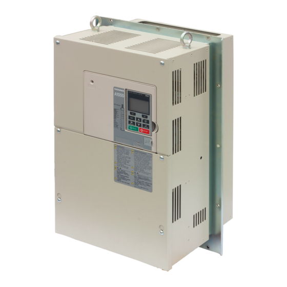
Page 32: Component Names
N - Terminal cover screw <1> The following drive models have a single cooling fan: CIMR-A 2A0021F, CIMR-A 4A0007F through 0011F. Drives CIMR-A 2A0004F through 0012F and CIMR-A 4A0002F through 0005F do not have a cooling fan or a cooling fan cover. - Page 33 ■ Three-Phase AC200 V CIMR-A 2A0169A to 0312A Three-Phase AC400 V CIMR-A 4A0139A to 0208A Table 1.6 Exploded view of IP00 Enclosure Type Components (CIMR-A 4A0165A) A - Mounting hole B - Heatsink C - Optional 24 V DC power supply connector cover...
- Page 34 N - Drive cover 2 O - Terminal cover Three-Phase AC400 V CIMR-A 4A0515A, 0675A ■ Table 1.9 Exploded view of IP00 Enclosure Type Components (CIMR-A 4A0515A, 0675A) A - Mounting hole B - Heatsink C - Terminal board D - Fan guard...
-
Page 35: Front Views
Circuit Wiring on page Analog/PTC Input Selection on page G – Main circuit terminal (Refer to Wiring the Main Circuit Terminal on page Figure 1.2 Front View of Drives YASKAWA ELECTRIC SIEP C710616 27C YASKAWA AC Drive A1000 Technical Manual... - Page 36 1.5 Component Names YASKAWA ELECTRIC SIEP C710616 27C YASKAWA AC Drive A1000 Technical Manual...
-
Page 37: Mechanical Installation
2.2 MECHANICAL INSTALLATION ........ -
Page 38: Section Safety
Failure to comply could result in damage to the drive. Place a temporary cover over the top during installation. Be sure to remove the temporary cover before start-up, as the cover will reduce ventilation and cause the unit to overheat. - Page 39 When using an explosion-proof motor, it must be subject to an explosion-proof test in conjunction with the drive. This is also applicable when an existing explosion-proof motor is to be operated with the drive. Since the drive itself is not explosion-proof, always install it in a safe place.
-
Page 40: Installation Environment
Drive reliability improves in environments without wide temperature fluctuations. Ambient Temperature When using the drive in an enclosure panel, install a cooling fan or air conditioner in the area to ensure that the air temperature inside the enclosure does not exceed the specified levels. - Page 41 Figure 2.3 Space Between Drives (Side-by-Side Mounting) Note: When installing drives of different heights in the same enclosure panel, the tops of the drives should line up. Leave space between the top and bottom of stacked drives for easy cooling fan replacement if required.
-
Page 42: Digital Operator Remote Usage
■ The digital operator mounted on the drive can be removed and connected to the drive using an extension cable up to 3 m long. This makes it easier to operate the drive when it is installed in a location where it can not be accessed easily. - Page 43 Note: Prevent foreign matter such as metal shavings or wire clippings from falling into the drive during installation and project construction. Failure to comply could result in damage to the drive. Place a temporary cover over the top of the drive during installation.
- Page 44 Unit: mm Figure 2.9 Internal/Flush Mount Installation Note: For environments with a significant amount of dust or other airborne debris, use a gasket between the enclosure panel and the digital operator. YASKAWA ELECTRIC SIEP C710616 27C YASKAWA AC Drive A1000 Technical Manual...
- Page 45 2.2 Mechanical Installation Figure 2.9 common_TMonly +0.5 Unit : mm Figure 2.10 Panel Cut-Out Dimensions (Internal/Flush-Mount Installation) YASKAWA ELECTRIC SIEP C710616 27C YASKAWA AC Drive A1000 Technical Manual...
-
Page 46: Exterior And Mounting Dimensions
2A0056F 4A0031F 2A0069F 4A0038F 2A0081F 4A0044F 4A0058A 4A0072A 4A0088A 2A0110A 4A0103A 2A0138A 4A0139A 2A0169A 4A0165A 2A0211A IP00 Enclosure 4A0208A 2A0250A 4A0250A 2A0312A 4A0296A 2A0360A 4A0362A 2A0415A 4A0414A 4A0515A 4A0675A YASKAWA ELECTRIC SIEP C710616 27C YASKAWA AC Drive A1000 Technical Manual... - Page 47 2.2 Mechanical Installation IP20/NEMA Type 1 Enclosure Drives ■ Note: IP20/NEMA Type 1 enclosure drives are equipped with a top cover. Removing this cover voids NEMA Type 1 protection but still keeps IP20 conformity. Figure 1 Figure 2 Table 2.4 Dimensions for IP20/NEMA Type 1 Enclosure: 200 V Class...
- Page 48 2.2 Mechanical Installation IP00 Enclosure Drives ■ Max 10 Max 10 Figure 1 Max 7.7 Max 7.7 Figure 2 Max 6 Max 6 Figure 3 YASKAWA ELECTRIC SIEP C710616 27C YASKAWA AC Drive A1000 Technical Manual...
- Page 49 Table 2.7 Dimensions for IP00 Enclosure: 400 V Class Dimensions (mm) Drive Model Weight CIMR-A 4A Figure (kg) 0058 0072 0088 0103 0139 0165 0208 12.5 0250 0296 0362 0414 0515 1140 1110 0675 1140 1110 YASKAWA ELECTRIC SIEP C710616 27C YASKAWA AC Drive A1000 Technical Manual...
- Page 50 2.2 Mechanical Installation YASKAWA ELECTRIC SIEP C710616 27C YASKAWA AC Drive A1000 Technical Manual...
-
Page 51: Electrical Installation
3.1 SECTION SAFETY........... 52 3.2 STANDARD CONNECTION DIAGRAM ........54 3.3 MAIN CIRCUIT CONNECTION DIAGRAM . -
Page 52: Section Safety
Before wiring terminals, disconnect all power to the equipment. The internal capacitor remains charged even after the power supply is turned off. After shutting off the power, wait for at least the amount of time specified on the drive before touching any components. - Page 53 Failure to comply could result in damage to the drive and will void warranty. Yaskawa is not responsible for any modification of the product made by the user. This product must not be modified. Check all the wiring to ensure that all connections are correct after installing the drive and connecting any other devices.
-
Page 54: Standard Connection Diagram
(200 V Class) and 480 Vac maximum (400 V Class). NOTICE: When the input voltage is 440 V or higher or the wiring distance is greater than 100 meters, pay special attention to the motor insulation voltage or use a drive duty motor. Failure to comply could lead to motor insulation breakdown. - Page 55 <6> The maximum current supplied by this voltage source is 150 mA if no digital input option card DI-A3 is used. <7> The maximum output current capacity for the +V and -V terminals on the control circuit is 20 mA. Never short terminals +V, -V, and AC, as this can cause erroneous operation or damage the drive.
-
Page 56: Main Circuit Connection Diagram
The DC power supply for the main circuit also provides power to the control circuit. NOTICE: Do not use the negative DC bus terminal “-” as a ground terminal. This terminal is at high DC voltage potential. Improper wiring connections could damage the drive. -
Page 57: Terminal Block Configuration
3.4 Terminal Block Configuration Terminal Block Configuration Figure 3.5 shows the different main circuit terminal arrangements for the drive capacities. Figure 3.8 CIMR-A 2A0056 CIMR-A 2A0004, 0006, 0010, 0012, CIMR-A 2A0030, 0040 CIMR-A 4A0031, 0038, 0044 0021 CIMR-A 4A0018, 0023... - Page 58 R/L1 S/L2 T/L3 U/T1 V/T2 W/T3 Figure 3.5 Main Circuit Terminal Block Configuration <1> Terminal board design differs slightly for models CIMR-A 2A0250 through 2A0415 and 4A0208 through 4A0362. YASKAWA ELECTRIC SIEP C710616 27C YASKAWA AC Drive A1000 Technical Manual...
-
Page 59: Terminal Cover
Figure 3.10 Figure 3.6 Removing the Terminal Cover on an IP20/NEMA Type 1 Enclosure Drive Push in on the hook located on the bottom of the terminal cover, and gently pull forward. This should remove the terminal cover. Figure 3.11 Figure 3.7 Removing the Terminal Cover on an IP20/NEMA Type 1 Enclosure Drive... -
Page 60: Cimr-A 2A0110 To 0415, 4A0058 To 0675 (Ip00 Enclosure)
<1> CAUTION! Do not completely remove the cover screws, just loosen them. If the cover screws are removed completely, the terminal cover may fall off causing an injury. <1> The following drives have three screws on the top of terminal cover. -
Page 61: Digital Operator And
Reattaching the Digital Operator Insert the digital operator into the opening in the front cover while aligning it with the notches on the left side of the opening. Next press gently on the right side of the operator until it clicks into place. - Page 62 Figure 3.15 Remove the Front Cover (2A0110 to 2A0415 and 4A0058 to 4A0675) First unhook the left side of the front cover, then swing the left side towards you as shown in the figure below until the cover comes off.
- Page 63 Removing the Front Cover on page 61 to reattach the front cover. Pinch inwards on the hooks found on each side of the front cover while guiding it back into the drive. Make sure it clicks firmly into place. 2A0110 to 2A0415 and 4A0058 to 4A0675 Slide the front cover so that the hooks on the top connect to the drive.
-
Page 64: Top Protective Cover
Gently apply pressure as shown in the figure below to free the cover from the drive. Note: Removing the top protective cover from a IP20/NEMA Type 1 enclosure drive voids the NEMA Type 1 protection but still keeps IP20 conformity. -
Page 65: Main Circuit Wiring
NOTICE: Do not switch the drive input to start or stop the motor. Frequently switching the drive on and off shortens the lifetime of the DC bus charge circuit and the DC bus capacitors, and can cause premature drive failures. For the full performance life, refrain from switching the drive on and off more than once every 30 minutes. -
Page 66: Wire Gauges And Tightening Torque
40°C and wiring distance less than 100 m. 2. Terminals +1, +2, +3, –, B1 and B2 are for connecting optional devices such as a DC reactor or braking resistor. Do not connect other nonspecific devices to these terminals. - Page 67 3.8 Main Circuit Wiring Three-Phase 200 V Class ■ Table 3.2 Wire Gauge and Torque Specifications (Three-Phase 200 V Class) Applicable Tightening Model Recommended Gauge Screw Terminal Gauge Torque CIMR-A Size N m (lb.in.) R/L1, S/L2, T/L3 2.5 to 6 U/T1, V/T2, W/T3 2.5 to 6...
- Page 68 – 70 to 300 (159 to 204) 32 to 40 120 to 240 (283 to 354) Three-Phase 400 V Class ■ Table 3.3 Wire Gauge and Torque Specifications (Three-Phase 400 V Class) Applicable Tightening Model Recommended Gauge Screw Terminal Gauge...
- Page 69 R/L1, S/L2, T/L3 50 to 95 U/T1, V/T2, W/T3 70 to 95 18 to 23 4A0165 –,+1 – 35 to 95 (159 to 204) – 50 to 95 25 to 35 YASKAWA ELECTRIC SIEP C710616 27C YASKAWA AC Drive A1000 Technical Manual...
-
Page 70: Main Circuit Terminal And Motor Wiring
LC/RC noise filters or ground fault circuit interrupters. NOTICE: Do not connect the AC power line to the output motor terminals of the drive. Failure to comply could result in death or serious injury by fire as a result of drive damage from line voltage application to output terminals. - Page 71 15 kHz or less 5 kHz or less 2 kHz or less Note: When setting carrier frequency in a drive running multiple motors, calculate the cable length as the total distance of wiring to all motors that are connected. Ground Wiring ■...
-
Page 72: Control Circuit Wiring
WARNING! Sudden Movement Hazard. Always check the operation and wiring of control circuits after being wired. Operating a drive with untested control circuits could result in death or serious injury. WARNING! Confirm the drive I/O signals and external sequence before starting test run. Setting parameter A1-06 may change the I/O terminal function automatically from the factory setting. -
Page 73: Terminal Configuration
Communications output (-) Shield ground <1> Enable the termination resistor in the last drive in a MEMOBUS network by setting DIP switch S2 to the ON position. For more information on the termination resistor, see Control I/O Connections on page ◆... -
Page 74: Wiring The Control Circuit Terminal
This section describes the proper procedures and preparations for wiring the control terminals. WARNING! Electrical Shock Hazard. Do not remove covers or touch the circuit boards while the power is on. Failure to comply could result in death or serious injury. - Page 75 If it fits tightly, e.g. if ferrules are used, turn the wire for about 45° and then pull it gently out. Use this procedure to remove the wire jumper between terminals HC, H1 and H2 that is preinstalled at shipping.
-
Page 76: Switches And Jumpers On The Terminal Board
3.9 Control Circuit Wiring ◆ Switches and Jumpers on the Terminal Board The terminal board is equipped with several switches used to adapt the drive I/Os to the external control signals. Figure 3.28 shows the location of these switches. Refer to Control I/O Connections on page 77 for setting instructions. -
Page 77: Control I/O Connections
◆ Sinking/Sourcing Mode Switch for Digital Inputs Use the wire link between terminals SC and SP or SC and SN to select between Sink mode, Source mode or external power supply for the digital inputs S1 to S8 as shown in Table 3.10... -
Page 78: Using The Pulse Train Output
◆ Using the Pulse Train Output The pulse train output terminal MP can either supply power but can also be used with external power supply. Peripheral devices should be connected in accordance with the specifications listed below. Failure to do so can cause unexpected drive operation, and can damage the drive or connected circuits. -
Page 79: Terminal A2 Input Signal Selection
Board on page 76 for locating switch S1. Note: If terminals A1 and A2 are both set for frequency bias (H3-02 = 0 and H3-10 = 0), both input values will be combined to create the frequency reference. Table 3.12 DIP Switch S1 Settings... -
Page 80: Memobus/Modbus Termination
Table 3.17. The OFF position is the default. The termination resistor should be placed to the ON position when the drive is the last in a series of slave drives. Refer to Switches and Jumpers on the Terminal Board on page 76 for locating switch S2. -
Page 81: Connect To A Pc
This drive is equipped with a USB port (type-B). The drive can connect to the USB port of a PC using a USB 2.0, AB type cable (sold separately). DriveWizard Plus can then be used to monitor drive performance and manage parameter settings. Contact Yaskawa for more information on DriveWizard Plus. -
Page 82: External Interlock
Two drives running a single application might interlock with the controller using the Drive ready and Fault output signals as shown below. The figure illustrates how the application would not be able to run if either drive experiences a fault or is unable to supply a Drive ready signal. -
Page 83: Wiring Checklist
Properly wire the drive and motor together. The motor lines and drive output terminals R/T1, V/T2, and W/T3 should match in order to produce the desired phase order. If the phase order is incorrect, the drive will rotate in the opposite direction. - Page 84 3.13 Wiring Checklist YASKAWA ELECTRIC SIEP C710616 27C YASKAWA AC Drive A1000 Technical Manual...
-
Page 85: Start-Up Programming & Operation
4.9 TEST RUN WITH LOAD CONNECTED........123... -
Page 86: Section Safety
A separate holding brake should be prepared by the user. The holding brake should be wired so that it is activated by an external sequence when a fault occurs, the power is shut off, or an emergency switch is triggered. -
Page 87: Using The Digital Operator
ALM LED Light <1> The STOP key has highest priority. Pressing the STOP key will always cause the drive to stop the motor, even if a Run command is active at any external Run command source. To disable the STOP key priority, set parameter o2-06 to 0. -
Page 88: Lcd Display
Displayed when the frequency reference is assigned to the drives Analog Input. Frequency Reference Displayed when the frequency reference is assigned to the drives MEMOBUS/Modbus Communication Inputs. Assignment <1> Displayed when the frequency reference is assigned to a drive Option Unit. -
Page 89: Alarm (Alm) Led Displays
Figure 4.3 RUN LED Status and Meaning Figure 4.4 Drive output frequency during stop STOP STOP 6 Hz common_TM 0 Hz Frequency setting only RUN LED Flashing Figure 4.4 RUN LED and Drive Operation YASKAWA ELECTRIC SIEP C710616 27C YASKAWA AC Drive A1000 Technical Manual... -
Page 90: Menu Structure For Digital Operator
Drive cannot operate the motor. <3> Flashing characters are shown as <4> X characters are shown in this manual. The LCD Operator will display the actual setting values. <5> The Frequency Reference appears after the initial display which shows the product name. <6>... -
Page 91: The Drive And Programming Modes
Programming Mode. Note: If parameter b1-08 is set to 0 the drive will accept a Run command only in the Drive Mode. When editing parameters, the user must first exit the Programming Mode and enter the Drive Mode before starting the motor. -
Page 92: Changing Parameter Settings Or Values
Figure 4.6 Setting the Frequency Reference while in the Drive Mode Note: The drive will not accept a change to the frequency reference until the ENTER key is pressed after the frequency reference is entered. This feature prevents accidental setting of the frequency reference. To have the drive accept changes to the frequency reference as soon as changes are made without requiring the ENTER key, set o2-05 to 1. - Page 93 (0.0~6000.0) “10.0 sec” ← → -PRMSET- Decel Time 1 C1-02= 0010.0Sec Press to view the current setting value (10.0 s). Left digit flashes. (0.0~6000.0) “10.0 sec” ← → -PRMSET- Decel Time 1 Press until the desired number is selected. “1” flashes.
-
Page 94: Verifying Parameter Changes: Verify Menu
Verify Menu will read “None”. The Verify Menu also allows users to quickly access and re-edit any parameters settings that have been changed. Note: The Verify Menu will not display parameters from the A1 group (except for A1-02) even if those parameters have been changed from their default settings. -
Page 95: Simplified Setup Using The Setup Group
Home DATA <1> Use the up and down arrow keys to scroll through the Setup Group. Press the ENTER key to view or change parameter settings. <2> To return to the previous menu without saving changes, press the ESC key. -
Page 96: Switching Between Local And Remote
Stall Prevention Selection during Deceleration Note: Parameter availability depends on the control mode set in A1-02 that is used to run the drive and motor. Consequently, some of the parameters listed above may not be accessible in certain control modes. - Page 97 4.3 The Drive and Programming Modes Using Input Terminals S1 through S8 to Switch between LO/RE ■ The user can also switch between LOCAL and REMOTE modes using one of the digital input terminals S1 through S8 (set the corresponding parameter H1- to “1”).
-
Page 98: Start-Up Flowcharts
Figure 4.8 Basic Start-up Note: When the motor cable length has changed for more than 50 m after Auto-Tuning has been performed (e.g., after the drive has been set up and then later installed in a different location), execute Stationary Auto-Tuning for resistance between motor lines once the drive is installed in its final installation location. -
Page 99: Subchart A-1: Simple Motor Setup Using V/F Control
Flowchart A1 in Figure 4.9 describes simple motor setup for V/f Control, with or without PG feedback. V/f Control is suited for more basic applications such as fans and pumps. This procedure illustrates Energy Savings and Speed Estimation Speed Search. Figure 4.8... -
Page 100: Subchart A-2: High Performance Operation Using Olv Or Clv
Note: Although the drive sets parameters for the PG encoder during Auto-Tuning, sometimes the direction of the motor and direction of the PG get reversed. Use parameter F1-05 to switch the direction of the PG so that it matches the motor direction. -
Page 101: Subchart A-3: Operation With Permanent Magnet Motors
Return to Flowchart <1> Enter the motor code to E5-01 when using a Yaskawa PM motor (SMRA Series, SSR1 Series, and SST4 Series). If using a motor from another manufacturer, enter FFFF. <2> Make sure the motor and load can run freely, i.e., if a brake is mounted, make sure it is released. -
Page 102: Powering Up The Drive
Status of the load and connected Decouple the motor from the load. machinery ■ Status Display When the power supply to the drive is turned on, the digital operator lights will appear as follows: Name Description DIGITAL OPERATOR JVOP-180 ALARM... -
Page 103: Application Selection
95) or in parameter A1-06. The following presets can be selected: Note: An Application Preset can only be selected if all drive parameters are on at their original default settings. It may be necessary to initialize the drive by setting A1-03 to “2220” or “3330” prior to selecting an Application Preset. -
Page 104: Setting 3: Exhaust Fan Application
Carrier Frequency Selection 3: 8.0 kHz H2-03 Terminals P2 Function Selection 39: Watt Hour Pulse Output 2: CPU Power Active - Drive will restart if power returns prior to control power L2-01 Momentary Power Loss Operation Selection supply shut down. L8-03... -
Page 105: Setting 5: Compressor Application
Motor Overload Protection Selection C1-02 Deceleration Time 1 L4-01 Speed Agreement Detection Level C6-02 Carrier Frequency Selection L6-02 Torque Detection Level 1 d1-01 Frequency Reference 1 L6-03 Torque Detection Time 1 YASKAWA ELECTRIC SIEP C710616 27C YASKAWA AC Drive A1000 Technical Manual... -
Page 106: Notes On Controlling The Brake When Using The Hoist Application Preset
<1> This is the setting recommended when using Open Loop Vector Control. If using V/f Control, set the level as the motor rated slip frequency plus 0.5 Hz. Not enough motor torque will be created if this value is set too low, and the load may tend to slip. Make sure this value is greater than the minimum output frequency and greater than the value of L4-02, as shown in the diagram below. - Page 107 Figure 4.13 Sequence Circuit Configuration • The brake should release just a bit after the Run command is issued, allowing the motor to build up torque. If using the V/f, V/f w PG or OLV control modes and the “Frequency detection 2” signal controls the brake, the motor can be given time to build up torque by setting the brake release level in parameter L4-01.
-
Page 108: Setting 7: Traveling Application
C6-02 Carrier Frequency Selection H1-06 Multi-Function Digital Input Terminal S6 Function d1-01 Frequency Reference 1 H2-01 Terminals M1-M2 Function Selection d1-02 Frequency Reference 2 L1-01 Motor Overload Protection Selection YASKAWA ELECTRIC SIEP C710616 27C YASKAWA AC Drive A1000 Technical Manual... -
Page 109: Auto-Tuning
Flowcharts on page Note: The drive will only show Auto-Tuning parameters that are valid for the control mode that has been set to A1-02. If the control mode is for an induction motor, the Auto-Tuning parameters for PM motors will not be available. If the control mode is for a PM motor, the Auto-Tuning parameters for induction motors will not be available. - Page 110 Inertia Tuning and Speed Control Loop Auto-Tuning Inertia Tuning can be performed when the drive is using Closed Loop Vector control for either IM or PM motors. Inertia Tuning automatically calculates load and motor inertia, and optimizes settings related to the KEB Ride-Thru function (KEB 2) and Feed Forward control.
-
Page 111: Before Auto-Tuning The Drive
• For best performance, the drive input supply voltage must be greater than the motor rated voltage. Note: Better performance is possible when using a motor with a base voltage that is 20 V (40 V for 400 V class models) lower than the input supply voltage. -
Page 112: Auto-Tuning Interruption And Fault Codes
WARNING! Electrical Shock Hazard. When executing Inertia Tuning or ASR Gain Auto-Tuning, voltage is applied to the motor even before it rotates. Do not touch the motor until Auto-Tuning is completed. Failure to comply may result in injury from electrical shock. - Page 113 T1-01= 0 ∗0∗ Standard Tuning DATA <1> T1-00 will appear on the display when one of the multi-function inputs has been set to switch between motor 1 and motor 2 (H1- = 16). Enter Data from the Motor Nameplate ■...
-
Page 114: Parameter Settings During Induction Motor Auto-Tuning: T1
Auto-Tuning input data for induction motor tuning. Note: For motors that are to be operated in the field weakening range, first perform the Auto-Tuning with the base data. After Auto- Tuning is complete, change the maximum frequency E1-04 to the desired value. - Page 115 Sets the motor rated frequency according to the motor nameplate value. If a motor with an extended speed range is used or the motor is used in the field weakening area, enter the maximum frequency to E1-04 (E3-04 for motor 2) after Auto- Tuning is complete.
-
Page 116: Parameter Settings During Pm Motor Auto-Tuning: T2
<1> This value's number of decimal places depends on the drive model and the Heavy/Normal duty selection in parameter C6-01. The value will have two decimal places (0.01 A) if the drive is set for a Maximum Applicable Motor Capacity up to 11 kW (refer Table A.2... - Page 117 0.0 to 255.0 V 200.0 V <1> <1> The setting range and default value shown here is for a 200 V class drive. These values double when using a 400 V class unit. T2-06: PM Motor Rated Current ■ Enter the motor rated current in amps.
- Page 118 Note: If T2-13 is set to 0, then the drive will use E5-24 (Motor Induction Voltage Constant 2), and will automatically set E5-09 (Motor Induction Voltage Constant 1) to 0.0. If T2-13 is set to 1, then the drive will use E5-09 and will automatically set E5-25 to 0.0.
-
Page 119: Parameter Settings During Inertia And Speed Control Loop Auto-Tuning: T3
Depending on E2-11 Note: The display resolution depends on the rated output power of the drive after the Drive Duty has been set in parameter C6-01. Drives with a maximum output up to 37 kW will display this value in units of 0.0001 kgm . - Page 120 Sets the response frequency (reciprocal of the step response time constant) of the system or the connected machine. The drive uses this value and the load inertia to fine-tune the speed control loop gain (C5-01, ASR Gain 1). Oscillation may result if the value input here is higher than the actual response frequency of the system.
-
Page 121: No-Load Operation Test Run
4.8 No-Load Operation Test Run No-Load Operation Test Run ◆ No-Load Operation Test Run This section explains how to operate the drive with the motor decoupled from the load during a test run. Before Starting the Motor ■ Check the following items before operation: •... - Page 122 LSEQ U1-03= 0.00A LREF FWD/REV STOP The drive should operate normally. Press to stop the motor. RUN flashes until the motor comes to a RESET ENTER complete stop. STOP YASKAWA ELECTRIC SIEP C710616 27C YASKAWA AC Drive A1000 Technical Manual...
-
Page 123: Test Run With Load Connected
• Watch monitor parameter U1-03 during operation to ensure there is no overcurrent. • If the application permits running the load in the reverse direction, try changing motor direction and the frequency reference while watching for abnormal motor oscillation or vibration. -
Page 124: Verifying Parameter Settings And Backing Up Changes
The following procedure saves all parameters settings to drive memory where they can later be recalled. Set o2-03 to “1” to save parameter changes. This saves all parameter settings, and then returns o2-03 to 0. The drive can now “recall” the saved parameters by performing a User Initialization (A1-03 = 1110). -
Page 125: Copy Function
• USB Copy Unit and CopyUnitManager The copy unit is an external option connected to the drive to copy parameter settings from one drive and save those settings to another drive. Refer to the manual supplied with the USB Copy Unit for instructions. -
Page 126: Test Run Checklist
Set the proper voltage to terminal A1 and A3 (-10 to +10 V). When current input is used, switch the drive’s built-in DIP switch S1 from the V-side to I-side. Set the level for current signal used to H3-09 (set “2” for 4 to 20 mA, or “3” for 0 to 20 mA). - Page 127 Checklist Page If the frequency reference is supplied via one of the analog inputs, make sure the analog input produces the desired frequency reference. Make the following adjustments if the drive does not operate as expected: Gain adjustment: Set the maximum voltage/current signal and adjust the analog input gain (H3-03 for input A1, H3-11 for input A2, H3-07 –...
- Page 128 4.11 Test Run Checklist YASKAWA ELECTRIC SIEP C710616 27C YASKAWA AC Drive A1000 Technical Manual...
-
Page 129: Parameter Details
5.9 N: SPECIAL ADJUSTMENTS ......... 275 5.10 O: OPERATOR RELATED SETTINGS ....... . . 284 5.11 U: MONITOR PARAMETERS . -
Page 130: A: Initialization
A1-02: Control Method Selection ■ Selects the Control Method (also referred to as the “control mode”) the drive uses to operate the motor. If the drive is set up to run two motors, then A1-02 determines the control mode for motor 1. - Page 131 Setting 7: Closed Loop Vector Control for PM This mode can be used for high precision control of a PM motor in constant torque or variable torque applications. The speed control range reaches 1:1500. A speed feedback signal is required.
- Page 132 How to use the Password The user can set a password for the drive to restrict access. The password is set to A1-05 and must be entered to A1-04 to unlock parameter access. Until the correct password is entered, the following parameters cannot be viewed or edited: A1- 01, A1-02, A1-03, A1-06, and A2-01 through A2-33.
- Page 133 Select Password The display automatically returns to the display shown in step 5. = 1234 (0~9999) “0” ← → Table 5.3 Check to see if A1-02 is locked (continuing from step 10 above) Step Display/Result -PRMSET- Control Method A1-02= 2 ∗2∗...
- Page 134 I/O terminals that best suit the application. All parameters changed when selecting an Application Preset are also assigned to the list of User Parameters, A2-01 through A2-16. These can be edited more easily in the Setup Mode and provide quicker access by eliminating the need to scroll through multiple menus.
-
Page 135: A2: User Parameters
Next assign the parameter number to the User Parameters list by entering it into one of the A2- parameters. If A1-01 is then set to 1, the access level can be restricted so that users can only set and refer to the specific parameters saved as User Parameters. -
Page 136: B: Application
Use parameter b1-01 to select the frequency reference source 1 for the REMOTE mode. Note: 1. If a Run command is input to the drive but the frequency reference entered is 0 or below the minimum frequency, the RUN indicator LED on the digital operator will light and the STOP indicator will flash. - Page 137 Note: If the frequency reference source is set for an option PCB (b1-01 = 3), but an option board is not installed, an OPE05 Operator Programming Error will be displayed on the digital operator and the drive will not run.
- Page 138 Note: If b1-02 is set to 3, but an option board is not installed in CN5-A, an oPE05 operator programming error will be displayed on the digital operator and the drive will not run.
- Page 139 Setting 3: Coast to Stop with Timer When the Run command is removed, the drive will turn off its output and the motor will coast to stop. If a Run command is input before the time t (value of C1-02) has expired, the drive will not start. A Run command activated during time t must be cycled after t has expired in order to start the drive.
- Page 140 5.2 b: Application The wait time t is determined by the output frequency when the Run command is removed and by the active deceleration time. Figure 5.7 Run wait time t Active deceleration time Min Baseblock Time (L2-03) 100% Min output...
- Page 141 Whenever a Run command is active and the frequency reference is smaller than the value of parameter E1-09, the drive runs the motor at the speed set in E1-09. When the Run command is removed, the drive decelerates the motor. As soon as the motor speed reaches the zero speed level set in b2-01, Zero Speed Control is activated for the time set in b2-04.
- Page 142 Run command is active at the new source as the switch over occurs, the drive will not start or will stop operation if it was running before. The Run command has to be cycled at the new source in order to start the drive again.
- Page 143 The Run command has to be cycled to start the drive. Note: For safety reasons, the drive is initially programmed not to accept a Run command at power up (b1-17 = 0). If a Run command is issued at power up, the RUN indicator LED will flash quickly.
-
Page 144: B2: Dc Injection Braking And Short Circuit Braking
WARNING! Sudden Movement Hazard. If b1-17 is set to 1 and an external Run command is active during power up, the motor will begin rotating as soon as the power is switched on. Proper precautions must be taken to ensure that the area around the motor is safe prior to powering up the drive. - Page 145 Figure 5.16 Magnetic Flux Compensation Note that the level of the DC current injected to the motor is limited to 80% of the drive rated current or to the motor rated current, whichever value is smaller. Note: 1. If b2-08 is set below 100%, it can take a relatively long time for flux to develop.
-
Page 146: B3: Speed Search
0.00 to 25.50 s 0.00 s Note: Short Circuit Braking cannot prevent a PM motor from being rotated by an external force. To prevent the load from rotating the motor, use DC Injection. b2-13: Short Circuit Brake Time at Stop ■... - Page 147 ■ This method can be used for a single induction motor connected to a drive. It should not be used if the motor is one or more frame sizes smaller than the drive, at motor speeds above 200 Hz, or when using a single drive to operate more than one motor.
- Page 148 <1> Once AC power is restored, the drive will wait for at least the time set to b3-05. If the power interruption is longer than the minimum baseblock time set to L2-03, the drive will wait until the time set to b3-05 has passed after power is restored before starting Speed Search.
- Page 149 Speed Search Deactivation Current 0 to 200% Determined by A1-02 Note: When parameter A1-02 = 0 (V/f Control) the factory default setting is 120. When parameter A1-02 = 2 (Open Loop Vector) the factory default setting is 100. b3-03: Speed Search Deceleration Time ■...
- Page 150 ■ Sets the current injected to the motor at the beginning of Speed Estimation Speed Search as a factor of the motor rated current set in E2-01 (E4-01 for motor 2). If the motor speed is relatively slow when the drive starts to perform Speed Search after a long period of baseblock, it may be helpful to increase the setting value.
-
Page 151: B4: Delay Timers
Number of Speed Search Restarts Sets the number of times the drive should attempt to find the speed and restart the motor. If the number of restart attempts exceeds the value set to b3-19, the SEr fault will occur and the drive will stop. -
Page 152: B5: Pid Control
■ P Control The output of P control is the product of the deviation and the P gain so that it follows the deviation directly and linearly. With P control, only an offset between the target and feedback remains. I Control ■... - Page 153 PID Setpoint Input Methods The PID setpoint input depends on the PID function setting in parameter b5-01. If parameter b5-01 is set to 1 or 2, the frequency reference in b1-01 (or b1-15) or one of the inputs listed in Table 5.8 becomes the PID setpoint.
- Page 154 5.2 b: Application PID Block Diagram ■ Figure 5.23 Figure 5.23 PID Block Diagram YASKAWA ELECTRIC SIEP C710616 27C YASKAWA AC Drive A1000 Technical Manual...
- Page 155 Proportional Gain Setting (P) Sets the P gain that is applied to the PID input. A large value will tend to reduce the error, but may cause instability (oscillations) if set too high. A low value may allow too much offset between the setpoint and feedback.
- Page 156 0.00 s Note: Useful when there is a fair amount of oscillation or when rigidity is low. Set to a value larger than the cycle of the resonant frequency. Increasing this time constant may reduce the responsiveness of the drive.
- Page 157 Setting 2: Feedback Loss Fault If the PID feedback value falls below the level set to b5-13 for longer than the time set to b5-14, a “FbL - Feedback Low” fault will be displayed. If the PID feedback value exceeds the level set to b5-36 for longer than the time set to b5-37, a “FbH - Feedback High”...
- Page 158 Sets the level that triggers PID Sleep. The drive goes into Sleep mode if the PID output or frequency reference is smaller than b5-15 for longer than the time set in b5-16. It resumes the operation when the PID output or frequency reference is above b5-15 for longer than the time set in b5-16.
- Page 159 PID Setpoint Value 0.00 to 100.00% 0.00% ■ b5-20: PID Setpoint Scaling Determines the units that the PID setpoint (b5-19) is set in and displayed. Also determines the units for monitors U5-01 and U5-04. Parameter Name Setting Range Default b5-20...
- Page 160 PID Setpoint User Display, PID Setpoint Display Digits ■ When parameter b5-20 is set to 3, the parameters b5-38 and b5-39 can be used to set a user defined display for the PID setpoint (b5-19) and PID feedback monitors (U5-01, U5-04).
-
Page 161: B6: Dwell Function
If used with induction motors, the Dwell function can help prevent speed loss when starting and stopping a heavy load. If running a PM motor in V/f control, the pause in acceleration allows the PM motor rotor to align with the stator field of the motor, thus reducing the starting current. -
Page 162: B7: Droop Control (Clv, Clv/Pm)
Droop Control Gain ■ Sets the amount of speed reduction when the torque reference is 100%. The gain is set as a percentage of the maximum output frequency. A setting of 0.0% disables the Droop control function. Parameter Name... -
Page 163: B8: Energy Saving
Adjust this setting while viewing the output power monitor (U1-08) and running the drive with a light load. A low setting results in less output voltage and less energy consumption, but too small a value will cause the motor to stall. -
Page 164: B9: Zero Servo
2. When the Zero Servo command has shut off, the Zero Servo Completion digital output width also shuts off. 3. Avoid using Zero Servo to lock 100% load for long periods, as this can trigger a fault. If such loads need to be held in place for long periods, either make sure the current is less than 50% of the drive rated current during Zero Servo, or use a larger capacity drive. -
Page 165: C: Tuning
Deceleration Time 4 (Motor 2 Accel Time 2) <1> The setting range for the acceleration and deceleration times is determined by the accel/decel time setting units in C1-10. For example, if the time is set in units of 0.01 s (C1-10 = 0), the setting range becomes 0.00 to 600.00 s. - Page 166 = 16), parameters C1-01 to C1-04 become accel/ decel time 1 and 2 for motor 1, while C1-05 to C1-08 become accel/decel time 1 and 2 for motor 2. Accel/decel times 1 and 2 can be switched for each motor using a digital inputs set to H1-...
-
Page 167: C2: S-Curve Characteristics
Setting 0: 0.01 s units The accel/decel times are set in 0.01 s units. The setting range will be 0.00 to 600.00 s. If any of the parameters C1-01 to C1-09 is set to 600.1 seconds or more, then C1-10 cannot be set to 0. - Page 168 Determined by A1-02 Note: Default setting is 0.0 in V/f Control (A1-02 = 0), and 1.0 in Open Loop Vector Control (A1-02 = 2). In Closed Loop Vector Control, slip compensation is used correct inaccuracies that can result from temperature fluctuation in the rotor.
- Page 169 Determined by E3-01 Note: Default setting is 0.0 in V/f Control (A1-02 = 0). Default setting is 1.0 in Open Loop Vector Control (A1-02 = 2) and Closed Loop Vector Control (A1-02 = 3). In Closed Loop Vector Control, slip compensation gain acts as an adaptable gain.
-
Page 170: C4: Torque Compensation
Adjust C4-01 so that the output current does not exceed the drive rated current. Note: 1. Refrain from adjusting torque compensation in Open Loop Vector Control, as it can have a negative effect on torque accuracy. 2. Refrain from adjusting this parameter in OLV/PM. Too high a value can cause overcompensation, resulting in motor oscillation. -
Page 171: C5: Automatic Speed Regulator (Asr)
Torque Compensation Primary Delay Time 2 0 to 10000 ms 150 ms Note: If C4-06 is set to a relatively large value, be sure to also increase the setting in n2-03 (AFR Time Constant 2) proportionally. C4-07: Motor 2 Torque Compensation Gain ■... - Page 172 C5-08 <1> Figure 5.36 Speed Control Block Diagram for CLV, AOLV/PM and CLV/PM <1> Advanced Open Loop Vector Control for PM motors estimates the speed using the motor model and does not require an encoder feedback signal. ■ Adjusting the ASR Parameters Before adjusting ASR parameters make sure all motor data have been set up correctly or Auto-Tuning has been performed.
- Page 173 C5-01, C5-03 / C5-02, C5-04: ASR Proportional Gain 1, 2 / ASR Integral Time 1, 2 These parameters can be used to adjust the responsiveness of the ASR. Note: C5-01 is automatically set when ASR Tuning is performed (T1-01 = 9 or T2-01 = 9). Parameter Name...
- Page 174 In these control modes, parameters C5-03 and C5-04 define the ASR gain an integral time at zero speed. The settings in C5-01 and C5-02 are used at speeds above the setting in C5-07. C5-07 is set to 0 as the default so that C5-01 and C5-02 are used over the entire speed range.
- Page 175 Enables integral operation during acceleration and deceleration. Integral operation should be used when driving a heavy load or a high inertia load, but can cause problems with overshoot at the end of acceleration and deceleration. Refer to ASR Setup Problems and Corrective Actions on page 173 to solve such problems.
- Page 176 C5-25: Motor 2 ASR Limit ■ Functions for motor 2 in the same way that C5-05 functions for motor 1. Sets the ASR output limit for motor 2 as a percentage of the maximum output frequency (E4-04). For more details, see C5-05: ASR Limit on page 174.
-
Page 177: C6: Carrier Frequency
Reset when C6-01 is changed. Note: The default setting for the carrier frequency differs based on the type of motor and the Duty Mode selection. The default is 2 kHz when the drive is set for Heavy Duty performance, and defaulted to “Swing PWM1” when set for Normal Duty performance. - Page 178 <1> The carrier frequency may need to be lowered if the motor cable is too long. Refer to the table below. <2> In Normal Duty, the carrier frequency default is for Swing PWM (C6-02 = 7), the same as setting 2 kHz. Increasing the carrier frequency is fine when the drive is set for Normal Duty, but remember that the drive rated current falls when the carrier frequency is increased.
- Page 179 The tables below show the drive output current depending on the carrier frequency settings. The 2 kHz value is equal to the Normal Duty rated current. If the carrier frequency is increased above 2 kHz in ND, the rated output current is reduced.
-
Page 180: D: Reference Settings
<1> The upper limit is determined by the maximum output frequency (E1-04) and upper limit for the frequency reference (d2-01). <2> Setting units are determined by parameter o1-03. The default is “Hz” (o1-03 = 0) in V/f, V/f w/PG, OLV, CLV, and OLV/PM control modes. - Page 181 5.4 d: Reference Settings • When the an analog input is set to “Auxiliary frequency 2” (H3-02, H2-06, or H2-10 = 3), then the value set to this input will be used as the Multi-Step Speed 3 instead of the value set to parameter d1-03. If no analog inputs are set for “Auxiliary frequency 2”, then d1-03 becomes the reference for Multi-Step Speed 3.
-
Page 182: D2: Frequency Upper/Lower Limits
Sets the minimum frequency reference as a percentage of the maximum output frequency. This limit applies to all frequency references. If a lower reference than this value is entered, the drive will run at the limit set to d2-02. If the drive is started with a lower reference than d2-02, it will accelerate up to d2-02. -
Page 183: D4: Frequency Reference Hold And Up/Down 2 Function
Figure 5.44 Jump Frequency Operation Note: 1. The drive will use the active accel/decel time to pass through the specified dead band range, but will not allow continuous operation in that range. 2. When setting more than one Jump frequency, make sure that d3-01 ≥ d3-02 ≥ d3-03. - Page 184 • Up/Down 2 with frequency reference from input sources other than the digital operator When a Run command is active and the Up/Down 2 command is released for longer than 5 s, the bias value will be saved in parameter d4-06. When restarting after the power is switched off, the drive will add the value saved in d4-06 as a bias to the frequency reference.
- Page 185 Setting d4-03 ≠ 0.0 Hz When an Up 2 or Down 2 command is enabled, the bias is increased or decreased in steps for the value set in d4-03. The frequency reference changes with the accel/decel times determined by parameter d4-04.
- Page 186 Setting 1: Reset Bias Value The bias is reset to 0% when both inputs Up 2 and Down 2 are either on or off. The drive will use the accel/decel time as selected in d4-04 to accelerate or decelerate to the frequency reference value.
- Page 187 Set this parameter to an appropriate value before using the Up/Down 2 function. Note: When the frequency reference is set by the digital operator (b1-01 = 0) and d4-01 = 1, the bias value will be added to the frequency reference if no Up/Down 2 command is received for 5 s, and will be reset to 0 afterwards.
-
Page 188: D5: Torque Control
Stop Position Gain 0.50 to 2.55 1.00 Increase the value if the motor stops before the desired stop position is reached. Decrease it if the motor stops too late. Also refer to b1-03: Stopping Method Selection on page 138 for details on simple positioning. - Page 189 – setting the torque compensation value. <1> Sets analog input terminals A1, A2, and A3 to supply the speed limit, torque reference, or torque compensation. An oPE error will occur if two analog inputs are set for the same function.
- Page 190 Speed Limitation and Speed Limit Bias ■ The speed limit setting is read from the input selected in parameter d5-03. A bias can be added to this speed limit using parameter d5-05 while parameter b5-08 determines how the speed limit bias is applied.
- Page 191 5.4 d: Reference Settings 2. Set d5-01 to 0 when switching between Torque Control and Speed Control. An oPE15 alarm will be triggered if parameter d5-01 is set to 1 while H1- is set to 71 at the same time.
-
Page 192: D6: Field Weakening And Field Forcing
5.4 d: Reference Settings d5-05: Speed Limit Bias ■ Using d5-05 a bias can be applied to the speed limit value. The bias is set as a percentage of the maximum output frequency. Refer to Speed Limitation and Speed Limit Bias on page 190. -
Page 193: D7: Offset Frequency
Setting 1: Enabled d6-06: Field Forcing Limit ■ Sets the maximum level to what the Field Forcing function can boost the excitation current reference. The value is set as a percentage of the motor no load current. Parameter Name Setting Range... -
Page 194: E: Motor Parameters
(overvoltage, Stall Prevention, etc.). NOTICE: Set parameter E1-01 to match the input voltage of the drive. Drive input voltage (not motor voltage) must be set in E1-01 for the protective features to function properly. Failure to set the correct drive input voltage will result in improper drive operation. - Page 195 The following tables show details on predefined V/f patterns. The following graphs are for 200 V class drives. Double the values when using a 400 V class drive. Predefined V/f Patterns for models CIMR-A 2A0004 to 0021 and CIMR-A 4A0002 to 0011 Table 5.22 Constant Torque Characteristics, Settings 0 to 3...
- Page 196 Predefined V/f Patterns for Models CIMR-A 2A0030 to 0211 and CIMR-A 4A0018 to 0103 The following graphs are for 200 V class drives. Double values when using a 400 V class drive. Table 5.26 Rated Torque Characteristics, Settings 0 to 3...
- Page 197 V/f Pattern Settings E1-04 to E1-13 If E1-03 is set to a preset V/f pattern (i.e., set to any value besides F), then the user can refer to parameters E1-04 through E1-13 to monitor the V/f pattern. To create a new V/f pattern, set E1-03 to F. Refer to Figure 5.53...
-
Page 198: E2: Motor 1 Parameters
Note: This value's number of decimal places depends on the drive model and the Heavy/Normal duty selection in parameter C6-01. The value will have two decimal places (0.01 A) if the drive is set for a Maximum Applicable Motor Capacity up to 11 kW (refer Table A.2... - Page 199 Note: This value's number of decimal places depends on the drive model and the Heavy/Normal duty selection in parameter C6-01. The value will have two decimal places (0.01 A) if the drive is set for a Maximum Applicable Motor Capacity up to 11 kW (refer Table A.2...
- Page 200 Enter the motor rated current listed on the nameplate of the motor to E2-01. Setting the Motor Rated Slip Use the base speed listed on the motor nameplate to calculate the rated slip. Refer to the formula below, then enter that value to E2-02.
-
Page 201: E3: V/F Pattern For Motor 2
• When there is a large amount of torque loss in a fan or pump application. Setting the Motor Iron Loss for Torque Compensation This value only needs to be set when using V/f Control. Enter this value in watts to E2-10. The drive uses this setting to improve the precision of torque compensation. -
Page 202: E4: Motor 2 Parameters
Note: 1. The following conditions must be true when setting up the V/f pattern: E3-09 ≤ E3-07 < E3-06 ≤ E3-11 ≤ E3-04 2. To make the V/f pattern a straight line at a frequency lower than E3-07, set E3-09 = E3-07. With this setting, E3-08 is disregarded. - Page 203 ■ E4-06: Motor 2 Leakage Inductance Sets the voltage drop due to motor leakage inductance as a percentage of rated voltage of motor 2. This value is automatically set during Auto-Tuning (Rotational Auto-Tuning and Stationary Auto-Tuning 1, 2). Parameter Name...
-
Page 204: E5: Pm Motor Settings
C6-01 and o2-04 Note: 1. If E5-01 was set a value besides FFFF and is then changed to FFFF, the value of parameters E5-02 through E5-24 will not change. 2. If using a different motor other than Yaskawa’s SMRA, SSR1, or SST4 series, then E5-01 should be set to FFFF. - Page 205 Determined by E5-01 Note: Ensure that E5-24 = 0 when setting parameter E5-09. An alarm will be triggered, however, if both E5-09 and E5-24 are set 0, or if neither parameter is set to 0. When E5-01 = FFFF, then E5-09 = 0.0.
-
Page 206: F: Option Settings
F1-02, F1-14: PG Open (PGo) Circuit Operation Selection, Detection Time ■ A PGo fault is triggered if the drive receives no pulse signal for longer than the time set in F1-14. The stopping method when PGo occurs should be set to parameter F1-02. - Page 207 F1-06, F1-35: PG 1, PG 2 Division Rate for PG Pulse Monitor Sets the ratio between the pulse input and the pulse output of a PG option card as a three digit number, where the first digit (n) sets the numerator and the second and third digit (m) set the denominator as shown below:...
- Page 208 CN5-B, CN5-C 0 to 10 dv3 Detection Selection Note: A common cause for a dv3 fault is the incorrect setting of E5-11. Make sure the correct Z pulse offset has been entered to E5-11. F1-19: dv4 Detection Selection (CLV/PM) ■...
-
Page 209: F2: Analog Input Card Settings
H3-03, H3-04: Terminal A1 Gain and Bias Settings on page 234. Note: Parameter setting error oPE05 will occur if option card terminals are set for separate input functions (F2-01 = 0) while b1-01 = 3. Setting 1: Combine input terminal values to create frequency reference With this setting, all three input signals on the AI-A3 option card are added together to create the frequency reference. -
Page 210: F4: Analog Monitor Card Settings
Parameters F4-02 and F4-04 determine the gain, while parameters F4-05 and F4-06 set the bias. These parameters are set as a percentage of the output signal from V1 and V2 where 100% equals 10 V output. The terminal output voltage is limited to 10 V. -
Page 211: F5: Digital Output Card Settings
F5-01 through F5-08: Digital Output Option Card Terminal Function Selection ■ When F5-09 = 2, the parameters listed in the table below are used to assign functions to the output terminals on the option card. Name... - Page 212 Setting 1: Reset F6- when the drive is initialized with A1-03 Note: F6-08 is not reset when the drive is initialized, but does determine whether initializing the drive with A1-03 resets the other communication parameters, F6- YASKAWA ELECTRIC SIEP C710616 27C YASKAWA AC Drive A1000 Technical Manual...
-
Page 213: Cc-Link Parameters
5.6 F: Option Settings ◆ CC-Link Parameters Parameters F6-04, F6-10, F6-11, and F6-14 set up the drive to operate on a CC-Link network. For details on parameter settings, refer to the YASKAWA AC Drive-Option Card CC-Link Installation Manual and Technical Manual. -
Page 214: H: Terminal Functions
H parameters are used to assign functions to the external terminals. ◆ H1: Multi-Function Digital Inputs H1-01 to H1-08: Functions for Terminals S1 to S8 ■ These parameters assign functions to the multi-function digital inputs. The various functions and their settings are listed below in Table 5.35. - Page 215 Note: 1. The Run command must be closed for more than 2 ms. 2. If the Run command is active at power up and b1-17 = 0 (Run command at power up not accepted), the Run LED will flash to indicate that protective functions are operating.
- Page 216 Baseblock (Interrupt output) NOTICE: If using baseblock in hoist applications, make sure the brake closes when the drive output is cut off by a Baseblock command triggered via one of the input terminals. Failure to do so will result in the motor suddenly coasting when the Baseblock command is entered, causing the load to slip.
- Page 217 When a Run command is applied, the lower limits work as follows: • If the lower limit is set by d2-02 only, the drive will accelerate to this limit as soon as a Run command is entered. • If the lower limit is determined by an analog input only, the drive will accelerate to the limit as long as the Run command and an Up or Down command are active.
- Page 218 5.7 H: Terminal Functions • If the lower limit is set by both an analog input and d2-02, and the analog limit is higher than the d2-02 value, then the drive will accelerate to the d2-02 value when a Run command is input. Once the d2-02 value is reached, it will continue acceleration to the analog limit only if an Up or Down command is set.
- Page 219 F1-02 to F1-04, F1-08 to F1-11, F1-14, F1-31 to F1-37 Note: 1. When using 2 motors, the motor overload protection selection (oL1) set to L1-01 applies to both motor 1 and motor 2. 2. It is not possible to switch between motor 1 and motor 2 during run. Doing so will trigger the “rUn” alarm.
- Page 220 Once the Analog Frequency Reference Sample/Hold function is held for at least 100 ms, the drive reads the analog input and changes the frequency reference to the newly sampled speed as illustrated in Figure 5.62.
- Page 221 Configures the drive for a 2-wire sequence. When an input terminal set to 40 closes, the drive operates in the forward direction. When an input set for 41 closes, the drive will operate in reverse. Closing both inputs at the same time will result in an external fault.
- Page 222 146 for more about Speed Search. Note: Operator error oPE03 will result if both Speed Search 1 and Speed Search 2 are set to the input terminals at the same time. Setting 63: Field Weakening Enabled in V/f Control. When closed, Field Weakening is performed. For details,...
- Page 223 Setting 75, 76: Up 2, Down 2 command The Up 2 and Down 2 function can be used to add a bias to the frequency reference. The input programmed for 75 will increase the bias and the input programmed for 76 will decrease it.
-
Page 224: H2: Multi-Function Digital Outputs
Single Drive KEB Ride-Thru 2 Note: KEB Ride-Thru 1 and 2 cannot both be assigned to the input terminals at the same time. Doing so will trigger an oPE3 error. Setting 7C, 7D: Short Circuit Braking (N.O., N.C.) (OLV/PM, AOLV/PM) An input programmed for this function can be used to activate Short Circuit Braking in Open Loop Vector control modes for PM motors. - Page 225 Output frequency is less than the minimum output frequency set to E1-09 or b2-01 Note: When using CLV or CLV/PM control modes, the zero speed level is defined by b2-01. In all other control modes, the zero speed level is the minimum output frequency set to E1-09.
- Page 226 Output frequency or motor speed and the frequency reference are both within the range of L4-01 ±L4-02. Note: Frequency detection works in both forward and reverse. The value of L4-01 is used as the detection level for both directions. Figure 5.68...
- Page 227 Closed Output frequency or motor speed is below L4-01 or has not exceeded L4-01 + L4-02. Note: Frequency detection works in both forward and reverse. The value of L4-01 is used as the detection level for both directions. Figure 5.69...
- Page 228 DC bus voltage has fallen below the trip level set to L2-05. Setting 8: During baseblock (N.O.) Output closes to indicate that the drive is in a baseblock state. While in baseblock, output transistors do not switch and no main circuit voltage is output.
- Page 229 Setting F: Through mode Select this setting when using the terminal in a pass-through mode. When set to F, an output does not trigger any function in the drive. Setting F, however, still allows the output status to be read by a PLC via a communication option or MEMOBUS/Modbus communications.
- Page 230 Output opens when the output frequency or motor speed (CLV, CLV/PM) rises above the detection level set in L4-03 plus the detection with set in L4-04. The terminal remains open until the output frequency or motor speed falls below the level set in L4-03.
- Page 231 An output set for “Restart enabled” closes once the drive begins attempting to restart after a fault has occurred. The fault restart function allows the drive to automatically clear a fault. The terminal set to 1E will close after the fault is cleared and the drive has begun attempting to restart.
- Page 232 Parameter b1-05 is set to 1, 2, or 3, and the frequency reference has fallen below the minimum output frequency (E1-09). Setting 32: During speed limit in Torque Control The motor torque and load torque are not in balance, causing the motor to accelerate. An output terminal set to 32 closes when the motor reaches the speed limit. Refer to...
- Page 233 Description Open REMOTE: The external reference that has been selected (either b1-01 and b1-02 or b1-15 and b1-16) is used as frequency reference and Run command source Closed LOCAL: The digital operator is used as frequency reference and Run command source Setting 3D: During Speed Search Output terminal closes while Speed Search is being performed.
-
Page 234: H3: Multi-Function Analog Inputs
Note: 1. A negative power output (i.e., regeneration) does not subtract from the total watt hours. 2. The drive keeps track of the watt hours as long as the control circuit has power. The value is reset when the power supply is shut off. - Page 235 • Gain H3-03 = 200%, bias H3-04 = 0, terminal A1 as frequency reference input (H3-02 = 0): An input 10 Vdc will be equivalent to a 200% frequency reference and 5 Vdc will be equivalent to a 100% frequency reference.
- Page 236 5.7 H: Terminal Functions When analog input A3 is used as PTC input set H3-06 = E and make sure switch S4 on the terminal board is set for PTC input. Also refer to Terminal A3 Analog/PTC Input Selection on page...
- Page 237 H3-02, H3-10, and H3-06 determine functions for terminals A1, A2, and A3. Note: The scaling of all input functions depends on the gain and bias settings for the analog inputs. Set these to appropriate values when selecting and adjusting analog input functions.
- Page 238 Using this setting, the overtorque/undertorque detection level for torque detection 1 (L6-01) can be set by an analog input. The analog input will replace the level set to L6-02. An analog input of 100% (10 V or 20 mA) will set a torque detection level equal to 100% drive rated current / motor rated torque.
-
Page 239: H4: Multi-Function Analog Outputs
Setting F, 1F: Through mode When set to F or 1F, an input does not affect any drive function, but the input level can still be read out by a PLC via a communication option or MEMOBUS/Modbus communications. - Page 240 100%. Parameter H4-03 and H4-06 set the terminal FM and AM output signal level when the value of the selected monitor is at 0%. Both are set as a percentage, where 100% equals 10 Vdc or 20 mA analog output and 0% equals 0 V or 4 mA.
-
Page 241: H5: Memobus/Modbus Serial Communication
5.7 H: Terminal Functions Example 3: To have an output signal of 3 V at terminal FM when the monitored value is at 0%, set H4-03 to 30%. Figure 5.84 Gain = 100% H4-07, 08 = 0 H4-07, 08 = 1... - Page 242 171 for adjusting the responsiveness. Note: 1. C5 parameters will appear when using V/f Control (A1-02 = 0) and when the pulse input RP function is set for simple PG feedback in V/f Control (H6-01 = 3). 2. If running two motors from the same drive, note that the V/f Control with simple PG feedback can be used for motor 1 only.
- Page 243 5.7 H: Terminal Functions ■ H6-03: Pulse Train Input Gain Sets the level of the input value selected in H6-01 when a pulse train signal with the frequency set in H6-02 is input to terminal RP. Name Setting Range Default...
-
Page 244: L: Protection Functions
H2-01 to 1F. The output will close when the motor overload level reaches 90% of the oL1 detection level. 2. Select a method to protect the motor from overheat by setting L1-01 between 1 and 5 when running a single motor from the drive. An external thermal relay is not needed. - Page 245 Use this setting when operating a drive duty motor that allows constant torque in a speed range of 1:10. The drive will allow the motor to run with 100% load from 10% up to 100% speed. Running at slower speeds with full load can trigger an overload fault.
- Page 246 L1-02: Motor Overload Protection Time ■ Sets the time it takes the drive to detect motor overheat due to overload. This setting rarely requires adjustment, but should correlate with the motor overload tolerance protection time for performing a hot start.
- Page 247 Motor Protection Using a Positive Temperature Coefficient (PTC) ■ A motor PTC can be connected to an analog input of the drive. This input is used by the drive for motor overheat protection. When the motor overheat alarm level is reached, an oH3 alarm will be triggered and the drive will continue operation as selected in L1-03.
- Page 248 The drive stops the motor using the Fast Stop time set in parameter C1-09. L1-05: Motor Temperature Input Filter Time (PTC input) ■ Used to set a filter on the PTC input signal in order to prevent a motor overheat fault from being mistakenly detected. Name Setting Range...
-
Page 249: L2: Momentary Power Loss Ride-Thru
0 to 5 Setting 0: Disabled (default) If power is not restored within 15 ms, a Uv1 fault will result and the drive will stop the motor. The motor coasts to stop. Setting 1: Recover within L2-02 When a momentary power loss occurs, the drive output will be shut off. Should the power return within the time set to parameter L2-02, th e drive will perform Speed Search and attempt to resume operation. - Page 250 • The DC bus voltage fell below the level specified in L2-05. The KEB operation will start as specified in L2-29. Note: KEB Ride-Thru 1 and 2 cannot both be assigned to input terminals at the same time. Attempting this will trigger an oPE3 error.
- Page 251 L2-11, then normal operation is resumed. Note: The time set in L2-02 has priority over L2-10. Even if L2-10 is set to a longer time than L2-02, once the time in L2-02 passes, the drive will check the DC bus voltage level and the status of the terminal assigned to KEB Ride-Thru, then try to restart.
- Page 252 = 65, 66, 7A, 7B). After decelerating for the time set in parameter L2-10, the drive checks the DC bus voltage and the status of the digital input. If the DC bus voltage is still below the level set in L2-11 or if the digital input assigned to KEB Ride-Thru is still active, then the drive continues to decelerate.
- Page 253 System KEB Ride-Thru 1 is used. Note: 1. Make sure the Run command is not switched off during momentary power loss. If the Run command is shut off, the drive will not accelerate back to speed when the power is restored.
- Page 254 0.00 to 6000.0 s 0.00 s <1> <1> Setting range is determined by the accel/decel time units set in C1-10. If the time is set in units of 0.01 s (C1-10 = 0), the setting range becomes 0.00 to 600.00 s. ■...
-
Page 255: L3: Stall Prevention
5.8 L: Protection Functions <1> Setting range is determined by the accel/decel time units set in C1-10. If the time is set in units of 0.01 s (C1-10 = 0), the setting range becomes 0.00 to 600.00 s. L2-08: Frequency Gain at KEB Start ■... - Page 256 <1> Setting 2 is not available for PM OLV. Setting 0: Disabled No Stall Prevention is provided. If the acceleration time is too short, the drive may not be able to get the motor up to speed fast enough, thus tripping an overload fault.
- Page 257 <1> <1> The upper limit and default value is determined by the duty rating and the carrier frequency derating selection (C6-01 and L8-38 respectively). • Stalling may occur when the motor is rated at a smaller capacity than the drive and the Stall Prevention default settings are used.
- Page 258 Setting 2: Intelligent Stall Prevention With this setting, the drive adjusts the deceleration rate so that the DC bus voltage is kept at the level set in parameter L3- 17. This way the shortest possible deceleration time is achieved while the motor is protected from stalling. The deceleration time that has been selected is disregarded, but the achievable deceleration time cannot be smaller than 1/10 of the set deceleration time.
- Page 259 2. When output frequency is 6 Hz or less, Stall Prevention during run is disabled regardless of the setting in L3-05 and L3-06. Setting 0: Disabled Drive runs at the set frequency reference. A heavy load may cause the motor to stall and trip the drive with an oC or oL fault.
- Page 260 • If this setting is too high, then a fair amount of speed or torque ripple can result. Adjustment for Overvoltage Suppression • Increase this setting slowly in steps of 0.1 if overvoltage suppression is enabled (L3-11 = 1) and a sudden increase in a regenerative load results in an overvoltage (ov) fault.
- Page 261 <1> <1> This value is reset to its default value when the control mode is changed (A1-02). The value shown here is for Open Loop Vector Control. Adjustment for Single Drive KEB 2 (L2-29 = 1) and Intelligent Stall Prevention During Deceleration •...
-
Page 262: L4: Speed Detection
Sets the capacity of any additional DC bus capacitors that have been installed. This data is used in calculations for Single Drive KEB Ride-Thru 2. This setting needs to be adjusted only if external capacity is connected to the drives DC bus and Single Drive KEB 2 is used. -
Page 263: L5: Fault Restart
L4-06: Frequency Reference at Reference Loss ■ Sets the frequency reference level the drive runs with when L4-05 = 1 and a reference loss was detected. The value is set as a percentage of the frequency reference before the loss was detected. -
Page 264: L6: Torque Detection
Setting 1: Count restart attempts The drive will try to restart using the time interval set in parameter L5-04. A record is kept of the number of attempts to restart to the drive, regardless of whether or not those attempts were successful. When the number of attempted restarts exceeds the value set to L5-01, the drive gives up trying to restart. - Page 265 Note: 1. The torque detection function uses a hysteresis of 10% of the drive rated output current and motor rated torque. 2. In V/f, V/f w/PG and OLV/PM, the level is set as a percentage of the drive rated output current. In OLV, CLV, AOLV/PM and CLV/ PM, it is set as a percentage of the motor rated torque.
- Page 266 These parameters set the detection levels for the torque detection functions 1 and 2. In V/f and OLV/PM control modes these levels are set as a percentage of the drive rated output current, while in vector control modes these levels are set as a percentage of the motor rated torque.
-
Page 267: L7: Torque Limit
110% The value is set as a percentage of the maximum frequency. If L6-08 is set for unsigned speed detection (L6-08 = 2, 4, 6, 8) then the absolute value of L6-09 is used (negative settings are treated as positive values). - Page 268 5.8 L: Protection Functions Example: If parameter L7-01 = 130%, L7-02 to L7-04 = 200%, and a general torque limit of 150% is set by an analog input (H2-02, H2-06, H2-10 = 15), then the torque limit in quadrant 1 will be 130%, but 150% in all other quadrants.
-
Page 269: L8: Drive Protection
= E), this output will be triggered. Setting 1: Coast to stop If heatsink overheat (oH) occurs, the drive switches off the output and the motor coasts to stop. If a digital output is programmed for “fault” (H2- = E), this output will be triggered. - Page 270 Figure 5.104 Output Frequency Reduction During Overheat Alarm L8-19: Frequency Reduction Rate during Overheat Pre-Alarm ■ Specifies how much the output frequency is reduced when L8-03 is set to 4 and an oH alarm is present. Set as a factor of the maximum output frequency. Name...
- Page 271 Setting 0: Run with timer The fan is switched on when a Run command is active. It is switched off with the delay set in parameter L8-11 after the Run command has been released. Using this setting extends the fan lifetime.
- Page 272 Setting 1: Software CLA enabled When the soft CLA current level is reached, the drive reduces the output voltage in order to reduce the current. If the current level drops below the Software CLA level, then normal operation will continue.
- Page 273 Note: 1. This parameter is not reset when the drive is initialized. 2. The value is preset to the appropriate value when the drive is shipped. Change the value only when using Side-by-Side installation or when mounting a standard drive with the heatsink outside the cabinet.
- Page 274 5.8 L: Protection Functions Setting 0: Disabled No alarm is detected. Setting 1: Enabled An alarm is triggered when the output current exceeds 150% of the drive rated current. A digital output set for an alarm (H2- = 10) will close. ■...
-
Page 275: N: Special Adjustments
Hunting Prevention Gain while in Reverse ■ This parameter is the same as n1-02, except that it is used when rotating in reverse. See the explanation for n1-02. Note: When set to 0 ms, n1-02 is enabled even when the drive is operating in reverse. -
Page 276: N2: Speed Feedback Detection Control (Afr) Tuning
Notes on using High Slip Braking: • The deceleration time that has been set is ignored during HSB. Use Overexcitation Deceleration 1 (L3-04 = 4) or a dynamic braking option if the motor has to be stopped in a defined time. - Page 277 • Lower this setting if motor current is too high during HSB. High current can damage the motor due to overheat. • The default setting is 150% when the drive is set for Heavy Duty, and 120% when the drive is set for Normal Duty.
- Page 278 Multiplies a gain to the V/f pattern output value during Overexcitation Deceleration, thereby determining the level of overexcitation. The drive returns to the normal V/f value after the motor has stopped or when it is accelerating to the frequency reference.
-
Page 279: N5: Feed Forward Control
Figure 5.106. Feed Forward can only be used in Closed Loop Vector Control for induction or PM motors (A1-02 = 4 or 7), or in Advanced Open Loop Vector Control for PM motors (A1-02 = 6). Figure 5.105 Suppresses... -
Page 280: N6: Online Tuning
Set the forward torque limit in parameter L7-01 to 100%. Set the frequency reference equal to the motor rated speed. While monitoring the motor speed in U1-05, start the motor in the forward direction and measure the time it takes to reach the rated speed. -
Page 281: N8: Pm Motor Control Tuning
Selects how the rotor position is detected at start. Note: 1. In CLV/PM, the drive performs a magnetic pole search the first time it starts the motor. After that, rotor position is calculated from the PG encoder signal and saved until the drive is switched off. Parameter n8-35 determines how this initial pole search operates. - Page 282 Although this setting rarely needs to be changed, adjustment may be necessary under the following conditions: • Increase this setting when it takes too long for the reference value of the pull-in current to match the target value. • Decrease this setting if motor oscillation occurs.
- Page 283 Load Inertia (OLV/PM) ■ Sets the ratio between motor inertia and the inertia of the connected machinery. If this value is set too low, the motor may not start very smoothly, and the STo fault (Motor Step-Out) may occur.
-
Page 284: O: Operator Related Settings
Setting 5: User-selected monitor (set by o1-01) o1-03: Digital Operator Display Selection ■ Sets the units used to display the frequency reference and output frequency. Set o1-03 to 3 for user-set units, then set parameters o1-10 and o1-11. Name Setting Range... -
Page 285: O2: Digital Operator Keypad Functions
WARNING! Sudden Movement Hazard. The drive may start unexpectedly if the Run command is already applied when switching from LOCAL mode to REMOTE mode when b1-07 = 1, resulting in death or serious injury. Check all mechanical or electrical connections thoroughly before making any setting changes to o2-01 and b1-07. - Page 286 ENTER key is pressed, the values are saved and the display returns to 0. Setting 2: Clear User Initialize Values All user-set defaults for “User Initialize” are cleared. Once o2-03 is set to 2 and the ENTER key is pressed, the values are erased and the display returns to 0.
-
Page 287: O3: Copy Function
Operation Selection when Digital Operator is Disconnected Determines if the drive will stop when the digital operator is removed in LOCAL mode or when b1-02 or b1-16 is set to 0. When the operator is reconnected, the display will indicate that it was disconnected. -
Page 288: O4: Maintenance Monitor Settings
Total operation time can be viewed in monitor U4-01. Note: The value in o4-01 is set in 10 h units. For example, a setting of 30 will set the cumulative operation time counter to 300 h. 300 h will also be displayed in monitor U4-01. -
Page 289: Q: Driveworksez Parameters
Setting 1: Number of Run Commands Counter Resets the Run command counter. The monitor U4-02 will show 0. Once o4-13 is set to 1 and the ENTER key is pressed, the counter value is erased and the display returns to 0. -
Page 290: T: Motor Tuning
5.10 o: Operator Related Settings ◆ T: Motor Tuning Auto-Tuning automatically sets and tunes parameters required for optimal motor performance. Refer to Auto-Tuning on page 109 for details on Auto-Tuning parameters. YASKAWA ELECTRIC SIEP C710616 27C YASKAWA AC Drive A1000 Technical Manual... -
Page 291: U: Monitor Parameters
◆ U3: Fault History These parameters display faults that have occurred during operation as well as the drive operation time when those faults occurred. Refer to U3: Fault History on page 450 for a complete list of U3- monitors and descriptions. -
Page 292: U8: Driveworksez Monitors
Refer to Setting 44, 45, 46: Offset frequency 1, 2, 3 on page 221. • The bias value added to the frequency reference by the Up/Down 2 function (see Setting 75, 76: Up 2, Down 2 command on page 223) -
Page 293: Troubleshooting
6.7 AUTO-TUNING FAULT DETECTION ........328... -
Page 294: Section Safety
Before wiring terminals, disconnect all power to the equipment. The internal capacitor remains charged even after the drive input power is turned off. After shutting off the power, wait for at least the amount of time specified on the drive before touching any components. - Page 295 Failure to comply could result in damage to the drive and will void warranty. Yaskawa is not responsible for modification of the product made by the user. Check all the wiring after installing the drive and connecting other devices to ensure that all connections are correct.
-
Page 296: Motor Performance Fine-Tuning
<2> Default settings change when the Control Method is changed (A1-02) or a different V/f pattern is selected using parameter E1-03. <3> ASR in V/f Control with PG only controls the output frequency, and therefore does not allow the high gain settings possible when using Close Loop Vector control. -
Page 297: Fine-Tuning Closed Loop Vector Control
<1> Default setting value is dependent on parameter A1-02, Control Method Selection, and o2-04, Drive Model Selection. <2> Default settings change when the Control Method is changed (A1-02) or a different V/f pattern is selected using parameter E1-03. When using OLV, leave the torque compensation gain (C4-01) at its default setting of 1.00. -
Page 298: Fine-Tuning Advanced Open Loop Vector Control For Pm Motors
Decel (n8-51) of 5% DC Injection Braking Current b2-03 = 0.5 s Use DC Injection Braking at start to align the rotor. Be aware that this b2-02 = 50% Oscillation at start or the motor stalls (b2-02), DC Injection Time at Increase b2-02 if operation can cause a short reverse rotation at start. -
Page 299: Parameters To Minimize Motor Hunting And Oscillation
Dwell Function (b6-01 through b6-04) backlash on the machine side. Used to balance the load between two motors that drive the same load. Can be used when the control method (A1-02) is set to Droop Function (b7-01, b7-02) 3 or 7. -
Page 300: Drive Alarms, Faults, And Errors
To reset the a minor fault or alarm, remove whatever is causing the problem. When parameter settings conflict with one another or do not match hardware settings (such as with an option card), it results in an operation error. When the... -
Page 301: Alarm And Error Displays
When the drive detects a fault, the ALM indicator LEDs lights and the fault code appears on the display. The drive fault contact MA-MB-MC will be triggered. If the ALM LED blinks and the code appearing on the operator screen is flashes, then an alarm has been detected. - Page 302 If an alarm is detected, the ALM LED will blink and the alarm code display flashes. The majority of alarms will trigger a digital output programmed for alarm output (H2- = 10).
- Page 303 During Run 2, Motor Switch Command Input MEMOBUS/Modbus Test Mode Fault TrPC IGBT Maintenance Time (90%) Undertorque 1 Undertorque 2 Mechanical Weakening Detection 2 Undervoltage Output Voltage Detection Fault <1> Output when H2- = 2F. YASKAWA ELECTRIC SIEP C710616 27C YASKAWA AC Drive A1000 Technical Manual...
- Page 304 Drive models do not match. Task completed iFEr Communication error ndAT Model, voltage class, capacity, and/or control mode differ rdEr Error reading data rEAd Reading parameter settings (flashing) YASKAWA ELECTRIC SIEP C710616 27C YASKAWA AC Drive A1000 Technical Manual...
- Page 305 Voltage class and/or drive capacity does not match vFyE Parameter settings in the drive and those saved to the copy function are not the same vrFy Comparing parameter settings (flashing) YASKAWA ELECTRIC SIEP C710616 27C YASKAWA AC Drive A1000 Technical Manual...
-
Page 306: Fault Detection
• Ensure that other equipment such as switches or relays do not cause noise. Use surge suppressors if necessary. • Use only recommended cables or other shielded line. Ground the shield on the controller side or on the drive input power side. - Page 307 Drive fails to operate properly due to noise interference. • Use only recommended cables or other shielded line. Ground the shield on the controller side or on the drive input power side. • Ensure that other equipment such as switches or relays do not cause noise and use surge suppressors if required.
- Page 308 The torque reference and acceleration are in opposite directions from one another (one is in reverse and the other is forward) while at the same time the speed reference and actual motor speed differ by over 30% for the number of pulses set to F1-18.
- Page 309 For instructions on replacing the power board, contact the Yaskawa sales office directly or your nearest Yaskawa representative. Digital Operator Display Fault Name Excessive PID Feedback PID feedback input is greater than the level set b5-36 for longer than the time set to b5-37. To enable fault detection, set b5-12 = 2 or 5. Cause Possible Solution Parameters are not set appropriately.
- Page 310 PID Feedback Loss This fault occurs when PID feedback loss detection is programmed to trigger a fault (b5-12 = 2) and the PID feedback level is below the detection level set to b5-13 for longer than the time set to b5-14.
- Page 311 The option board connection to port CN5-A is faulty. • If the option is not a communication option card, try to use the card in another option port. If it works there, replace the drive. If the error persists (oFb01 or oFC01 occur), replace the option board.
- Page 312 The option board connection to port CN5-C is faulty. • Try to use the card in another option port (in case of a PG option use port CN5-B). If it works there, replace the drive. If the error persists (oFA01 or oFb01 occur), replace the option board.
- Page 313 • Cycle power to the drive. Option card or hardware is damaged. • If the problem continues, replace either the control board or the entire drive. For instructions on replacing the control board, contact Yaskawa or your nearest sales representative.
- Page 314 • Increase the speed. with too high load. • If the motor is supposed to operate at low speeds, either increase the motor capacity or use a motor specifically designed to operate in the desired speed range. Adjust the user-set V/f patterns (E1-04 through E1-10). Parameters E1-08 and E1-10 may need to be reduced. Be careful not to The output voltage is too high.
- Page 315 External operator is not properly connected to the drive. • Replace the cable if damaged. • Turn off the drive input power and disconnect the operator. Next reconnect the operator and turn the drive input power back on. Digital Operator Display...
- Page 316 • Select the optimal braking resistor. Note: The magnitude of the braking load trips the braking resistor overheat alarm, NOT the surface temperature. Using the braking resistor more frequently than it is rated for trips the alarm even when the braking resistor surface is not very hot.
- Page 317 • For 200 V class: approximately 190 V • For 400 V class: approximately 380 V (350 V when E1-01 is less than 400) The fault is output only if L2-01 = 0 or L2-01 = 1 and the DC bus voltage has fallen below the level set to L2-05 for longer than the time set to L2-02.
- Page 318 • Cycle power to the drive. Check if the fault reoccurs. Internal circuitry is damaged. • If the problem continues, replace either the control board or the entire drive. For instructions on replacing the control board, contact Yaskawa or your nearest sales representative.
-
Page 319: Alarm Detection
• Use surge absorbers on magnetic contactors or other equipment causing the disturbance. • Use recommended cables or some other type of shielded line. Ground the shield to the controller side or on the input power side. • All wiring for comm. devices should be separated from drive input power lines. Install an EMC noise filter to the drive input power. - Page 320 • Use only recommended shielded line. Ground the shield on the controller side or on the drive input power side. • Separate all wiring for comm. devices from drive input power lines. Install an EMC noise filter to the drive input power supply.
- Page 321 Digital Operator Display Minor Fault Name Excessive PID Feedback The PID feedback input is higher than the level set in b5-36 for longer than the time set in b5-37, and b5-12 is set to 1 or 4. Cause Possible Solutions Parameters settings for b5-36 and b5-37 are Check parameters b5-36 and b5-37.
- Page 322 • Repair or replace the motor cooling system. Digital Operator Display Minor Fault Name Overtorque 1 Drive output current (or torque in OLV, CLV, AOLV/PM, CLV/PM) was greater than L6-02 for longer than the time set in L6-03. Cause Possible Solutions Inappropriate parameter settings.
- Page 323 • Install a DC reactor or an AC reactor. Surge voltage present in the drive input power. • Voltage surge can result from a thyristor convertor and a phase advancing capacitor operating on the same drive input power system. The motor is short-circuited.
- Page 324 • DC bus voltage dropped below the level specified in L2-05. • Contactor to suppress inrush current in the drive was opened. • Low voltage in the control drive input power. This alarm outputs only if L2-01 is not 0 and DC bus voltage is under L2-05. Cause Possible Solutions Phase loss in the drive input power.
-
Page 325: Operator Programming Errors
An Operator Programming Error (oPE) occurs when a contradictory parameter is set or an individual parameter is set to an inappropriate value. The drive will not operate until the parameter or parameters causing the problem are set correctly. An oPE, however, does not trigger an alarm or fault output. If an oPE occurs, investigate the cause and... - Page 326 (E1-09) is set lower than 1/20 of the base frequency setting. Note: Use U1-18 to find which parameters are set outside the specified setting range. Other errors are given precedence over oPE08 when multiple errors occur at the same time.
- Page 327 Cause Possible Solutions Scaling for the pulse train monitor is set to 0 (H6-07 = 0) while H6-06 is not set to 101, 102, Change scaling for the pulse train monitor or set H6-06 to 101, 102, 105, or 116.
-
Page 328: Auto-Tuning Fault Detection
• Enter proper information to parameters T1-03 to T1-05 and repeat Auto-Tuning. • If possible, disconnect the motor from the load and perform Auto-Tuning. If the load cannot be uncoupled, simply use the Auto- The results from Auto-Tuning the no-load current Tuning results as they are. - Page 329 • Perform Rotational Auto-Tuning. • Disconnect the motor from machine and restart Auto-Tuning. If motor and load cannot be uncoupled make sure the load is lower The load during Rotational Auto-tuning was too than 30%.
- Page 330 • Increase the torque limits in L7-01 through L7-04 (but keep them within reasonable limits). The output torque reached the torque limit set in L7- • First try reducing the test signal amplitude in T3-01 and repeat the tuning. If necessary, then try reducing the test signal frequency 01 through L7-04 during Inertia Tuning.
- Page 331 Check the direction and number of pulses set for the PG encoder. Repeat Auto-Tuning. wrong. PG encoder is damaged. Check the signal output from the PG encoder attached to the motor. Replace the PG if damaged. YASKAWA ELECTRIC SIEP C710616 27C YASKAWA AC Drive A1000 Technical Manual...
-
Page 332: Copy Function Related Displays
Control mode of the parameters to be loaded onto the drive Check the control mode for the parameters that are to be loaded onto the drive and the control mode set to the drive and the control mode already set to the drive don’t match. - Page 333 Cause Possible Solutions Failed while attempting to read parameter settings from the Press and hold the READ key on the USB Copy Unit for at least one second to have the unit read parameters from the drive. drive. Digital Operator Display...
-
Page 334: Diagnosing And Resetting Faults
Remove the cause of the fault and reset. Note: 1. To find out what faults were triggered, check the fault history in U2-02. Information on drive status when the fault occurred such as the frequency, current, and voltage can be found in U2-03 through U2-20. -
Page 335: Fault Reset Methods
If the above methods do not reset the fault, turn off the drive main power supply. Reapply power after the digital operator display is out. Note: If the Run command is present, the drive will disregard any attempts to reset the fault. The Run command must first be removed before a fault situation can be cleared. -
Page 336: Troubleshooting Without Fault Display
• See what mode the operator is currently set for. The operator is not in the Parameter Setup Mode (the screen will • Parameters cannot be edited when in the Setup Mode (“STUP”). Switch modes so that “PAr” appears on the screen. display “PAr”). -
Page 337: Entering External Run Command
• If the drive is supposed to be set up for a 2-wire sequence, then ensure parameters H1-03 through H1-08 are not set to 0. The sequence Start/Stop sequence is set up • If the drive is supposed to be set up for a 3-wire sequence, then one of the parameters H1-03 through H1-08 must be set to 0. Terminal S1 incorrectly. -
Page 338: Motor Is Too Hot
Cause Possible Solutions • The user is trying to set the motor rated current in E2-01 to a value lower than the no-load current set in E2-03. Motor rated current and the motor no-load current setting in the • Make sure that value set in E2-01 is higher than E2-03. -
Page 339: Reference Command
Reaching the torque limit. • If multi-function analog input terminal A1, A2, or A3 is set to torque limit (H3-02, H3-10, or H3-06 equals 10, 11, 12, or 15), ensure that the analog input levels are set to the correct levels. -
Page 340: Noise From Drive Or Output Lines When The Drive Is Powered On
• Place the motor on a rubber pad to reduce vibration. Note: The drive may have trouble assessing the status of the load due to white noise generated from using Swing PWM (C6-02 = 7 to A). Oscillation or Hunting ■... -
Page 341: Output Frequency Is Not As High As Frequency Reference
◆ Buzzing Sound from Motor at 2 kHz Cause Possible Solutions • If the output current rises too high at low speeds, the carrier frequency is automatically reduced and causes a whining or buzzing sound. Exceeded 110% of the rated output current of the drive while •... - Page 342 6.10 Troubleshooting without Fault Display YASKAWA ELECTRIC SIEP C710616 27C YASKAWA AC Drive A1000 Technical Manual...
-
Page 343: Periodic Inspection & Maintenance
7.3 PERIODIC MAINTENANCE ......... . . 349 7.4 COOLING FAN AND CIRCULATION FAN ....... 351 7.5 DRIVE REPLACEMENT . -
Page 344: Section Safety
Before wiring terminals, disconnect all power to the equipment. The internal capacitor remains charged even after the power supply is turned off. After shutting off the power, wait for at least the amount of time specified on the drive before touching any components. - Page 345 Follow the instructions in this manual to replace the cooling fan, making sure that the label is on top before inserting the cooling fan into the drive. To ensure maximum useful product life, replace both cooling fans when performing maintenance.
- Page 346 To get the full performance life out of the electrolytic capacitors and circuit relays, refrain from switching the drive power supply off and on more than once every 30 minutes. Frequent use can damage the drive. Use the drive to stop and start the motor.
-
Page 347: Inspection
7.2 Inspection Inspection Power electronics have limited life and may exhibit changes in characteristics or performance deterioration after years of use under normal conditions. To help avoid such problems, it is important to perform preventive maintenance and periodic inspection on the drive. -
Page 348: Recommended Periodic Inspection
Before servicing the drive, disconnect all power to the equipment. The internal capacitor remains charged even after the power supply is turned off. After shutting off the power, wait for at least the amount of time specified on the drive before touching any components. -
Page 349: Periodic Maintenance
Table 7.4 Performance Life Monitors Used for Component Replacement Parameter Component Contents Displays the accumulated operation time of the fan, from 0 to 99999 hours. This value is automatically reset to 0 once it U4-03 Cooling Fan, Circulation Fan, reaches 99999. - Page 350 = 10). <2> This alarm message will always be output, even if the Maintenance Monitor function is not assigned to any of the digital outputs (H2- 2F). The alarm will also trigger a digital output that is programmed for alarm indication (H2- = 10).
-
Page 351: Cooling Fan And Circulation Fan
7.4 Cooling Fan and Circulation Fan Cooling Fan and Circulation Fan NOTICE: Follow cooling fan replacement instructions. The cooling fan cannot operate properly when installed incorrectly and could seriously damage the drive. To ensure maximum useful product life, replace all cooling fans when performing maintenance. -
Page 352: Cooling Fan Component Names
Before servicing the drive, disconnect all power to the equipment. The internal capacitor remains charged even after the power supply is turned off. After shutting off the power, wait for at least the amount of time specified on the drive before touching any components. -
Page 353: Cooling Fan Replacement: 2A0021 To 2A0081 And 4A0007 To 4A0044
Before servicing the drive, disconnect all power to the equipment. The internal capacitor remains charged even after the power supply is turned off. After shutting off the power, wait for at least the amount of time specified on the drive before touching any components. - Page 354 B – Front Figure 7.5 Cooling Fan Power Supply Connectors: 2A0021 to 2A0081, 4A0007 to 4A0044 While pressing in on the hooks on the left and right sides of the fan cover, guide the fan cover until it clicks back into place.
-
Page 355: Cooling Fan Replacement: 2A0110 And 2A0138, 4A0058 And 4A0072
Before servicing the drive, disconnect all power to the equipment. The internal capacitor remains charged even after the power supply is turned off. After shutting off the power, wait for at least the amount of time specified on the drive before touching any components. - Page 356 Figure 7.10 Installing the Cooling Fan: 2A0110 and 2A0138, 4A0058 and 4A0072 Angle the fan cover so the back end tilts up. Slide the cover into the small opening towards the front of the drive, and then guide the entire fan cover into place.
-
Page 357: Cooling Fan Replacement: 4A0088 And 4A0103
Before servicing the drive, disconnect all power to the equipment. The internal capacitor remains charged even after the power supply is turned off. After shutting off the power, wait for at least the amount of time specified on the drive before touching any components. - Page 358 ■ Reverse the procedure described above to reinstall the cooling fan. Install the replacement fan into the drive, ensuring the alignment pins line up as shown in the figure below. Figure 7.15 Figure 7.15 Installing the Cooling Fan: 4A0088 and 4A0103 Make sure the power lines for the fan are properly connected, then place the power supply connectors and cable back into the recess of the drive.
-
Page 359: Cooling Fan Replacement: 2A0169 To 2A0415, 4A0139 To 4A0362
Before servicing the drive, disconnect all power to the equipment. The internal capacitor remains charged even after the power supply is turned off. After shutting off the power, wait for at least the amount of time specified on the drive before touching any components. - Page 360 7.4 Cooling Fan and Circulation Fan Remove the screws holding the fan unit in place and slide the fan unit out of the drive. Figure 7.20 Figure 7.20 Removing the Fan Unit: 2A0169 to 2A0415, 4A0139 to 4A0362 Remove the fan guard and replace the cooling fans.
- Page 361 Position the protective tube so that the fan connector sits in the center of the protective tube. Protective tube Place the connector for fan B2 before the B1 connector and guide the lead wire for fan B2 so that it is held in place by the cable hook.
- Page 362 Position the protective tube so that the fan connector sits in the center of the protective tube. Protective tube The fan connector for fan B2 should be placed in front of the fan B1 connector between fans B1 and B2. The connector for fan B3 should be pressed in between fan B2 and B3.
-
Page 363: Cooling Fan Replacement: 4A0414
Before servicing the drive, disconnect all power to the equipment. The internal capacitor remains charged even after the power supply is turned off. After shutting off the power, wait for at least the amount of time specified on the drive before touching any components. - Page 364 Figure 7.28 Fan Unit Disassembly: 4A0414 ■ Cooling Fan Wiring Position the protective tube so that the fan connector sits in the center of the protective tube. Protective tube Place the fan connector covered by the tube as shown in the drawings below.
-
Page 365: Cooling Fan Replacement: 4A0515 And 4A0675
Before servicing the drive, disconnect all power to the equipment. The internal capacitor remains charged even after the power supply is turned off. After shutting off the power, wait for at least the amount of time specified on the drive before touching any components. - Page 366 Figure 7.32 Removing the Fan Unit: 4A0515 and 4A0675 Remove the slide panel and fan unit along with the cooling fan unit for the circuit boards from the drive. Note: Both the fan unit and slide panel should be removed at the same time.
- Page 367 Figure 7.36 Fan Unit Disassembly: 4A0515 and 4A0675 Cooling Fan Wiring ■ Place the cooling fan connectors and guide the lead wires so that they are held in place by the cable hooks. Figure 7.37 Cooling Fan B2 Cooling Fan B3...
- Page 368 7.4 Cooling Fan and Circulation Fan Guide the lead wires so that they are held in place by the cable hooks and place the circulation fan connectors between the fan and fan unit. Figure 7.38 Relay Connector Cooling Fan B3...
-
Page 369: Drive Replacement
Once transferred, there is no need to manually reprogram the replacement drive. Note: If the damaged drive and the new replacement drive are have different capacities, the data stored in the terminal board cannot be transferred to the new drive and an oPE01 error will appear on the display. -
Page 370: Replacing The Drive
Before servicing the drive, disconnect all power to the equipment. The internal capacitor remains charged even after the power supply is turned off. After shutting off the power, wait for at least the amount of time specified on the drive before touching any components. - Page 371 Figure 7.46 Drive Replacement: Installing the Terminal Board Reconnect all options to the new drive in the same way they were installed in the old drive. Connect option boards to the same option ports in the new drive that were used in the old drive.
- Page 372 7.5 Drive Replacement YASKAWA ELECTRIC SIEP C710616 27C YASKAWA AC Drive A1000 Technical Manual...
-
Page 373: Peripheral Devices & Options
8.4 OPTION CARD INSTALLATION ........377 8.5 INSTALLING PERIPHERAL DEVICES ........379... -
Page 374: Section Safety
Failure to comply will result in death or serious injury. The internal capacitor remains charged even after the power supply is turned off. After shutting off the power, wait for at least the amount of time specified on the drive before touching any components. -
Page 375: Drive Options And Peripheral Devices
8.2 Drive Options and Peripheral Devices Drive Options and Peripheral Devices The following table of peripheral devices lists the names of the various accessories and options available for Yaskawa drives. Contact Yaskawa or your Yaskawa agent to order these peripheral devices. -
Page 376: Connecting Peripheral Devices
Figure 8.1 illustrates how to configure the drive and motor to operate with various peripheral devices. • For more detailed instructions on how to install each device shown below, refer to the specific manual for that device. Figure 8.1 Engineering Software Tools... -
Page 377: Option Card Installation
DO-A3, AO-A3 CN5-A, B, C <1> If installed to CN5-B or CN5-C, AI-A3 and DI-A3 cannot be used to set the frequency reference, but the input status can still be viewed using U1-21, U1-22, U1-23 (for AI-A3), and U1-17 (for DI-A3). - Page 378 Some option cards come with several different lead lines for connecting the card to the drive. Select the lead line with the most appropriate length. Note: There are only two screw holes on the drive for ground terminals. If three option cards are connected, two of the lead lines will need to share the same ground terminal.
-
Page 379: Installing Peripheral Devices
Carefully review the braking resistor instruction manual when connecting a braking resistor option to the drive. Note: 1. The braking circuit must be sized properly in order to dissipate the power required to decelerate the load in the desired time. Ensure that the braking circuit can dissipate the energy for the set deceleration time prior to running the drive. - Page 380 Connect the braking resistor to the CDBRs terminals +0 and -0. Wire the thermal overload relay contact of the CDBR and the braking resistor in series, and connect this signal to a drive digital input. Use this input to trigger a fault in the drive in case a CDBR or braking resistor overload occurs.
-
Page 381: Installing A Molded Case Circuit Breaker (Mccb)
Wire the thermal overload contacts relays of all CDBRs and all braking resistors in series, then connect this signal to a drive digital input. This input can be used to trigger a fault in the drive in case of overload in any of the CDBRs or braking resistors. -
Page 382: Installing A Magnetic Contactor
Improper sequencing of output motor circuits could result in damage to the drive. NOTICE: Install a MC on the input side of the drive when the drive should not automatically restart after power loss. To get the full performance life out of the electrolytic capacitors and circuit relays, refrain from switching the drive power supply off and on more than once every 30 minutes. -
Page 383: Connecting An Ac Or Dc Reactor
• With a large capacity power supply transformer (over 600 kVA). Note: Use an AC or DC reactor when also connecting a thyristor converter (such as a DC drive) to the same power supply system, regardless of the conditions of the power supply. - Page 384 8.5 Installing Peripheral Devices • Use shielded motor and control circuit lines and lay control circuit lines at least 30 cm away from power lines in order to prevent malfunction due to induced noise. Figure 8.13 MCCB R/L1 U/T1 S/L2...
-
Page 385: Installing Input Fuses
Figure 8.15 Output-Side Noise Filter ◆ Installing Input Fuses Yaskawa recommends installing a fuse to the input side of the drive to prevent damage to the drive if a short circuit occurs. Select the appropriate fuse from the table below. -
Page 386: Installing A Motor Thermal Overload (Ol) Relay On The Drive Output
• When using a power line bypass to operate the motor directly from the power line. It is not necessary to install a motor thermal overload relay when operating a single motor from a single AC drive. The AC drive has UL recognized electronic motor overload protection built into the drive software. -
Page 387: A. Specifications
A.2 THREE-PHASE 200 V CLASS DRIVES ....... . . 389... -
Page 388: Heavy Duty And Normal Duty Ratings
TERMS TERMS needs. The drive allows the user to select HD or ND torque depending on the application. Fans, pumps, and blowers should use ND (C6-01 = 1), and other applications generally use HD (C6-01 = 0). Swing PWM: Swing PWM equivalent to a 2 kHz audible noise. This function turns the motor noise into a less obtrusive white noise. -
Page 389: Three-Phase 200 V Class Drives
400 Hz (user-set) Maximum Output Frequency (Hz) <1> The motor capacity (kW) refers to a Yaskawa 4-pole motor. The rated output current of the drive output amps should be equal to or greater than the motor rated current. <2> Assumes operation at the rated output current. Input current rating varies depending on the power supply transformer, input reactor, wiring connections, and power supply impedance. -
Page 390: Three-Phase 400 V Class Drives
150 Hz (user-adjustable) Maximum Output Frequency (Hz) <1> The motor capacity (kW) refers to a Yaskawa 4-pole motor. The rated output current of the drive output amps should be equal to or greater than the motor rated current. <2> Assumes operation at the rated output current. Input current rating varies depending on the power supply transformer, input reactor, wiring conditions, and power supply impedance. -
Page 391: Drive Specifications
Accel/Decel Time Approx. 20% (approx. 125% when using braking resistor) <2> Short-time decel torque : over 100% for 0.4/ 0.75 kW motors, over 50% for 1.5 kW motors, and over 20% for 2.2 kW and <3> Braking Torque above motors (over excitation braking/High Slip Braking: approx. - Page 392 2 s. <8> Ground protection cannot be provided when the impedance of the ground fault path is too low, or when the drive is powered up while a ground fault is present at the output.
-
Page 393: Drive Watt Loss Data
2672 3626 <3> <1> These values assume the carrier frequency is set to 8 kHz. <2> These values assume the carrier frequency is set to 5 kHz. <3> These values assume the carrier frequency is set to 2 kHz. Table A.6 Watt Loss 400 V Class Three-Phase Models... -
Page 394: Drive Derating Data
The drive can be operated at above the rated temperature, altitude, and default carrier frequency by derating the drive capacity. ◆ Carrier Frequency Derating As the carrier frequency of the drive is increased above the factory default setting, the drive’s rated output current must be derated according to Figure A.1 Figure A.6. -
Page 395: Temperature Derating
Side-by-Side mounted in a cabinet. In order to ensure reliable drive overload protection, the parameters L8-12 and L8-35 must also be set according to the installation conditions. -
Page 396: Altitude Derating
◆ Altitude Derating The drive standard ratings are valid for an installation altitude up to 1000 m. If the altitude exceeds 1000 m both the drive rated voltage and the rated output current must be derated for 1% per 100 m. The maximum altitude is 3000 m. -
Page 397: B. Parameter List
B.5 V/F PATTERN DEFAULT VALUES ........ -
Page 398: Understanding The Parameter Table
Motor 2 Refers to a second motor when the drive is operating two motors. Switch between these motors using the multi-function input terminals. Note: If a parameter is not available in a certain control mode, the symbol for that control mode is grayed out. -
Page 399: Parameter Groups
Fault History Digital Input Card (DI-A3) Maintenance Monitors Analog Monitor Card (AO-A3) PID Monitors Digital Output Card (DO-A3) Operation Status Monitors Communication Option Card DriveWorksEZ Monitors Multi-Function Digital Inputs YASKAWA ELECTRIC SIEP C710616 27C YASKAWA AC Drive A1000 Technical Manual... -
Page 400: Parameter Table
17 through A2-32 for quick access. <1> Default setting value is dependent on parameter A1-06. This setting value is 0 when A1-06 = 0, and 1 when A1-06 does not equal 0. <2> Default setting value is determined by the Application Preset selected with parameter A1-06. -
Page 401: B: Application
Digital Input Reading 0: Input status is read once and processed immediately (for quick response) Min: 0 (185H) 1: Input is read twice and processed only if the status is the same in both readings (robust Max: 1 against noisy signals) common_... - Page 402 Determines the current level for Short Circuit Braking. Set as a percentage of the motor rated current. <7> A coasting motor may require a braking resistor circuit to bring the motor to a stop in the required time. <10> Default setting is determined by the control mode (A1-02).
- Page 403 Max: 30.0 s Sets the time the must wait between each Speed Search restart attempt. <9> Default setting value is dependent on the drive model (o2-04) and the Drive Duty (C6-01). <10> Default setting is determined by the control mode (A1-02).
- Page 404 Default: 0.00% All Modes TMonly b5-19 PID Setpoint Value Min: 0.00% (1DDH) Sets the PID target value when b5-18 = 1. Set as a percentage of the maximum output Max: 100.00% frequency. common_ All Modes TMonly Default: 1 b5-20 0: 0.01Hz units...
- Page 405 Sets the limit for the voltage search operation as a percentage of the motor rated voltage. <4> Default setting is dependent on the control mode (A1-02), the drive model (o2-04), and the Drive Duty (C6-01). <8> Parameter value changes automatically if E2-11 is manually changed or changed by Auto-Tuning.
-
Page 406: C: Tuning
Sets the frequency to switch between accel/decel time settings Max: 400.0 Hz <12> Setting range value is dependent on parameter C1-10, Accel/Decel Time Setting Units. When C1-10 = 0 (units of 0.01 seconds), the setting range becomes 0.00 to 600.00 seconds. - Page 407 AOLV/PM CLV/PM Motor 2 Slip Compensation Limit Min: 0% (242H) Max: 250% Sets the upper limit for the slip compensation function for motor 2. Set as a percentage of the motor rated slip (E4-02). V/f w/PG common_ TMonly Default: 0...
- Page 408 ASR Limit OLV/PM AOLV/PM CLV/PM Min: 0.0% (21FH) Max: 20.0% Sets the upper limit for the speed control loop (ASR) as a percentage of the maximum output frequency (E1-04). V/f w/PG Default: <10> common_ C5-06 ASR Primary Delay Time Constant TMonly Min: 0.000 s...
- Page 409 Sets the ratio between the motor 2 and machine inertia. This value is automatically set during ASR or Inertia Auto-Tuning. <9> Default setting is dependent on the control mode (A1-02), the drive model (o2-04), and the Drive Duty (C6-01). <10> Default setting is determined by the control mode (A1-02).
- Page 410 0: Carrier Frequency = 5 kHz 1: Setting value for C6-03 <4> Default setting is dependent on the control mode (A1-02), the drive model (o2-04), and the Drive Duty (C6-01). <13> Default setting value is dependent on the carrier frequency selection (C6-02).
-
Page 411: D: References
Sets the jog frequency reference. Setting units are determined by parameter o1-03. <20> <26> <20> Range upper limit is determined by the maximum output frequency (E1-04) and the upper limit of the frequency reference (d2-01). <26> The setting range is 0.0 to 66.0 in AOLV/PM. - Page 412 (2AFH) Frequency Reference Bias Upper TMonly Min: 0.0% Limit (Up/Down 2) Sets the upper limit for the bias and the value that can be saved in d4-06. Set as a percentage of Max: 100.0% the maximum output frequency. d4-09 common_ Default: 0.0%...
- Page 413 (29DH) Sets the speed limit during Torque Control as a percentage of the maximum output frequency. Max: 120% Enabled when d5-03 = 2. A negative setting set a limit in the opposite direction of the Run command. V/f w/PG common_...
-
Page 414: E: Motor Parameters
Max: E1-04 <29> E1-09 ≤ E1-07 < E1-06 ≤ Ε1−11 ≤ E1-04 Default: <4> Note that if E1-11 = 0, then both E1-11 and E1-12 are disabled, and the above conditions do not E1-07 Middle Output Frequency Min: 0.0 apply. - Page 415 <27> When Auto-Tuning is performed, E1-13 and E1-05 will be set to the same value. <29> The setting range varies according to the motor code entered to E5-01 when using OLV/PM. The setting range is 0.0 to 400.0 Hz when E5-01 is set to FFFFH.
- Page 416 <18> Values shown here are for 200 V class drives. Double the value when using a 400 V class drive. <24> Parameter ignored when E3-11 (Motor 2 Mid Output Frequency 2) and E3-12 (Motor 2 Mid Output Frequency Voltage 2) are set to 0.
- Page 417 <9> Default setting value is dependent on the drive model (o2-04) and the Drive Duty (C6-01). <19> This value's number of decimal places depends on the drive model and the Heavy/Normal duty selection in parameter C6-01. The value will have two decimal places (0.01 A) if the drive is set for a Maximum Applicable Motor Capacity up to 11 kW (refer to Table A.2...
-
Page 418: F: Options
<14> Default setting value is dependent on the motor code set to E5-01. <19> This value's number of decimal places depends on the drive model and the Heavy/Normal duty selection in parameter C6-01. The value will have two decimal places (0.01 A) if the drive is set for a Maximum Applicable Motor Capacity up to 11 kW (refer to Table A.2... - Page 419 Monitor Max: 132 Sets the division ratio for the pulse monitor used of the PG option card 2 installed to connector CN5-B. By setting “xyz”, the division ratio becomes = [(1 + x) / yz]. YASKAWA ELECTRIC SIEP C710616 27C YASKAWA AC Drive A1000 Technical Manual...
- Page 420 6: BCD customized setting (5 digit), 0.02 Hz units 7: Binary input When the digital operator units are set to be displayed in Hertz or user-set units (o1-03 = 2 or 3), the units for F3-01 are determined by parameter o1-03.
- Page 421 F6-01 through F6-03 and F6-06 through F6-08 are common settings used for CC-Link, CANopen, DeviceNet, PROFIBUS-DP, and MECHATROLINK-II option cards. Other parameters in the F6 group are used for communication protocol specific settings. For more details on a specific option card, refer to the instruction manual for the option card. No.(Addr.) Name...
- Page 422 Default: 21 common_ F6-52 All Modes TMonly DeviceNet PCA Setting Min: 0 – (3C3H) Sets the format of the data set from the DeviceNet master to the drive. Max: 255 YASKAWA ELECTRIC SIEP C710616 27C YASKAWA AC Drive A1000 Technical Manual...
-
Page 423: H Parameters: Multi-Function Terminals
Multi-Function Digital Input Min: 0 (405H) Terminal S8 Function Selection Max: 9F <31> Value in parenthesis is the default setting when a 3-wire initialization is performed (A1-03 = 3330). YASKAWA ELECTRIC SIEP C710616 27C YASKAWA AC Drive A1000 Technical Manual... - Page 424 Closed: Jog frequency reference (d1-17) selected. Jog has priority over all other reference sources. common_ All Modes Accel/Decel Time Selection 1 TMonly Used to switch between accel/decel time 1 (set in C1-01, C1-02) and accel/decel time 2 (set in C1-03, C1-04). common_ All Modes Baseblock Command (N.O.) TMonly...
- Page 425 Open: Decelerates to stop at the Fast Stop time set to C1-09. common_ All Modes TMonly Timer Function Input Triggers the timer set up by parameters b4-01 and b4-02. Must be set in conjunction with the timer function output (H2- = 12). common_ All Modes...
- Page 426 Up 2 Command All Modes TMonly Used to control the bias added to the frequency reference by the Up/Down 2 function. The Up 2 and Down 2 Down 2 Command commands must always be used in conjunction with one another.
- Page 427 Closed: Output frequency and speed reference equal L4-01 (plus or minus the hysteresis set to L4-02). common_ All Modes Frequency Detection 1 TMonly Closed: Output frequency is less than or equal to the value in L4-01 with hysteresis determined by L4-02. common_ All Modes Frequency Detection 2 TMonly Closed: Output frequency is greater than or equal to the value in L4-01 with hysteresis determined by L4-02.
- Page 428 Closed: An alarm has been triggered, or the IGBTs have reached 90% of their expected life span. common_ All Modes Fault Reset Command Active TMonly Closed: A command has been entered to clear a fault via the input terminals or from the serial network. common_ All Modes Timer Output TMonly Closed: Timer output.
- Page 429 Setting common_ All Modes TMonly Motor Overload Alarm (oL1) Closed: oL1 is at 90% of its trip point or greater. An oH3 situation also triggers this alarm. common_ All Modes Drive Overheat Pre-alarm (oH) TMonly Closed: Heatsink temperature exceeds the parameter L8-02 value.
- Page 430 (41AH) All Modes Terminal A2 Bias Setting TMonly Min: -999.9% Sets the level of the input value selected in H3-10 when 0 V (0 or 4 mA) is input at terminal A2. Max: 999.9% Default: 0.03 s common_ H3-13 All Modes...
- Page 431 All Modes Frequency Gain TMonly 0 to 10 V signal allows a setting of 0 to 100%. -10 to 0 V signal allows a setting of -100 to 0%. common_ Auxiliary Frequency Reference 1 (used as a All Modes...
- Page 432 (41EH) Multi-Function Analog Output All Modes TMonly Min: -999.9% Terminal FM Gain Sets the signal level at terminal FM that is equal to 100% of the selected monitor value. Max: 999.9% H4-03 Default: 0.0% common_ (41FH) Multi-Function Analog Output...
- Page 433 Default: 100.0% All Modes (42EH) TMonly Pulse Train Input Gain Min: 0.0% Sets the level of the value selected in H6-01 when a frequency with the value set in H6-02 is Max: 1000.0% input. H6-04 Default: 0.0% common_ (42FH)
-
Page 434: L: Protection Function
0: Disabled. Drive trips on (Uv1) fault when power is lost. Default: 0 L2-01 Momentary Power Loss Operation 1: Recover within the time set in L2-02. Uv1 will be detected if power loss is longer than L2-02. Min: 0 (485H) Selection 2: Recover as long as CPU has power. - Page 435 <9> Default setting is determined by the drive model (o2-04) and duty selection (C6-01). <12> Setting range value is dependent on the units selected for the accel/decel time (C1-10). When C1-10 = 0 (units of 0.01 s), the setting range becomes 0.00 to 600.00 s.
- Page 436 <34> Setting range is dependent on the control mode (A1-02). When using CLV, OLV/PM, or AOLV/PM, the setting range is 0 to 2 s. <35> The upper limit of the setting range is determined by the values set to the duty selection (C6-01) and the carrier frequency reduction selection (L8-38).
- Page 437 Number of Auto Restart Attempts Min: 0 (49EH) Sets the number of times the drive may attempt to restart after the following faults occur: GF, Max: 10 LF, oC, ov, PF, rH, rr, oL1, oL2, oL3, oL4, STo, Uv1. common_...
- Page 438 All Modes TMonly Min: 0 s (4B7H) Time Max: 300 s Sets a delay time to shut off the cooling fan after the Run command is removed when L8-10 = 0. Default: 40°C common_ L8-12 All Modes Ambient Temperature Setting TMonly Min: -10°C...
-
Page 439: N: Special Adjustment
AOLV/PM CLV/PM Min: 0.00 (581H) Max: 2.50 If the motor vibrates while lightly loaded, increase the gain by 0.1 until vibration ceases. If the motor stalls, decrease the gain by 0.1 until the stalling ceases. V/f w/PG Default: <6> common_... - Page 440 2: Enabled only when in reverse <35> The upper limit of the setting range is determined by the values set to duty selection (C6-01) and the carrier frequency reduction selection (L8-38). YASKAWA ELECTRIC SIEP C710616 27C YASKAWA AC Drive A1000 Technical Manual...
- Page 441 Sets the time constant to make the pull-in current reference and actual current value agree. Max: 100.0 s Decrease the value if the motor begins to oscillate, and increase the value if it takes too long for the current reference to equal the output current.
-
Page 442: O: Operator Related Settings
Sets the gain used for internal speed feedback detection during ov suppression <14> Default setting value is dependent on the motor code set to E5-01. <18> Values shown here are for 200 V class drives. Double the value when using a 400 V class drive. ◆ o: Operator Related Settings The o parameters are used to set up the digital operator displays. - Page 443 1: Read parameters from the drive, saving them onto the digital operator. Max: 3 2: Copy parameters from the digital operator, writing them to the drive. 3: Verify parameter settings on the drive to check if they match the data saved on the operator. common_ Default: 0...
-
Page 444: R: Driveworksez Connection Parameters
TMonly kWh Monitor Initialization Min: 0 (512H) 0: U4-10 and U4-11 monitor data is not reset when the drive is initialized (A1-03). Max: 1 1: U4-10 and U4-11 monitor data is reset when the drive is initialized (A1-03). common_ Default: 0... - Page 445 Sets the iron loss for determining the Energy Saving coefficient. Max: 65535 W The value is set to E2-10 (motor iron loss) set when the power is cycled. If T1-02 is changed, a default value appropriate for the motor capacity that was entered will appear.
- Page 446 <16> Default setting is determined by the control mode (A1-02) and the drive model (o2-04). <18> Values shown here are for 200 V class drives. Double the value when using a 400 V class drive. <39> Default setting is determined by the drive capacity and the motor code selected in T2-02.
-
Page 447: U: Monitors
B.3 Parameter Table ◆ U: Monitors Monitor parameters allow the user to view drive status, fault information, and other data concerning drive operation. U1: Operation Status Monitors ■ Analog Output No. (Addr.) Name Description Unit Page Level common_ U1-01 All Modes... - Page 448 DI-A3 Input Status – – (58H) available Display will appear in hexadecimal as determined by the digital card input selection in F3-01. 3FFFF: Set (1 bit) + sign (1 bit) + 16 bit common_ U1-18 No signal output All Modes...
- Page 449 (0.1 A) if the set Maximum Applicable Motor Capacity is higher than 11 kW. <22> The display resolution depends on the rated output power of the drive after the Drive Duty has been set in parameter C6-01. Drives with a maximum output up to 11 kW will display this value in units of 0.01 kW (two decimal places).
- Page 450 (0.1 A) if the set Maximum Applicable Motor Capacity is higher than 11 kW. <50> When reading the value of this monitor via MEMOBUS/Modbus a value of 8192 is equal to 100% of the drive rated output current.
- Page 451 Displays drive control data set by an option card as a four-digit hexadecimal number. <50> When reading the value of this monitor via MEMOBUS/Modbus a value of 8192 is equal to 100% of the drive rated output current. U5: PID Monitors ■...
- Page 452 AOLV/PM CLV/PM Control Axis Deviation (Δθ) 0.1 deg (7C1H) –10 V: –180 deg Displays the amount of deviation between the actual d-axis / q-axis and the γ-axis / δ-axis used for motor control. V/f w/PG common_ U6-13 Flux Position Detection...
- Page 453 (6CH) OLV/PM AOLV/PM CLV/PM current Output monitor for Feed Forward control. <18> Values shown here are for 200 V class drives. Double the value when using a 400 V class drive. U8: DriveWorksEZ Monitors ■ Analog Output No. (Addr.) Name...
-
Page 454: Control Mode Dependent Parameter Default Values
B.4 Control Mode Dependent Parameter Default Values The tables below list parameters that depend on the control mode selection (A1-02 for motor 1, E3-01 for motor 2). These parameters are initialized to the shown values if the control mode is changed. -
Page 455: E3-01 (Motor 2 Control Mode) Dependent Parameters
OLV (2) CLV (3) V/f Pattern The default setting of these parameters depends on the control mode but also on the drive capacity They are equivalent to the motor 1 settings. Refer to E3-04 to E3-10 Default Values on page 456... -
Page 456: V/F Pattern Default Values
B.5 V/f Pattern Default Values B.5 V/f Pattern Default Values The tables below show the V/f pattern settings default values depending on the control mode (A1-02) and the V/f pattern selection (E1-03 in V/f Control). Table B.5 E1-03 V/f Pattern Settings for Drive Capacity:... -
Page 457: Defaults By Drive Model Selection (O2-04) And Nd/Hd (C6-01)
B.6 Defaults by Drive Model Selection (o2-04) and ND/HD (C6-01) B.6 Defaults by Drive Model Selection (o2-04) and ND/HD (C6-01) The following tables show parameters and default settings that change with the drive model selection (o2-04). Parameter numbers shown in parenthesis are valid for motor 2. - Page 458 Overheat Alarm Level L8-35 Installation Method Selection – L8-38 Carrier Frequency Reduction Selection – n1-03 Hunting Prevention Time Constant n5-02 Motor Acceleration Time 0.32 0.387 0.387 0.317 0.317 0.533 YASKAWA ELECTRIC SIEP C710616 27C YASKAWA AC Drive A1000 Technical Manual...
- Page 459 Hunting Prevention Time Constant n5-02 Motor Acceleration Time 0.533 0.592 0.592 0.646 0.646 0.646 Table B.9 400 V Class Drives Default Settings by Drive Capacity and ND/HD Setting Name Unit Default Settings Model CIMR-A – 4A0002 4A0004 4A0005 4A0007...
- Page 460 °C L8-35 Installation Method Selection – L8-38 Carrier Frequency Reduction Selection – n1-03 Hunting Prevention Time Constant n5-02 Motor Acceleration Time 0.265 0.244 0.244 0.317 0.317 0.355 0.355 0.323 YASKAWA ELECTRIC SIEP C710616 27C YASKAWA AC Drive A1000 Technical Manual...
- Page 461 Overheat Alarm Level L8-35 Installation Method Selection – L8-38 Carrier Frequency Reduction Selection – n1-03 Hunting Prevention Time Constant n5-02 Motor Acceleration Time 0.533 0.592 0.592 0.646 0.646 0.673 0.673 0.777 YASKAWA ELECTRIC SIEP C710616 27C YASKAWA AC Drive A1000 Technical Manual...
- Page 462 Overheat Alarm Level L8-35 Installation Method Selection – L8-38 Carrier Frequency Reduction Selection – n1-03 Hunting Prevention Time Constant n5-02 Motor Acceleration Time 0.777 0.864 0.864 0.91 0.91 1.392 1.392 1.667 YASKAWA ELECTRIC SIEP C710616 27C YASKAWA AC Drive A1000 Technical Manual...
-
Page 463: Parameters That Change With The Motor Code Selection
B.7 Parameters that Change with the Motor Code Selection B.7 Parameters that Change with the Motor Code Selection The following tables show parameters and default settings that change with the motor code selection E5-01 when Open Loop Vector for PM motors is used. -
Page 464: Yaskawa Ssr1 Series Ipm Motor (For Derated Torque)
B.7 Parameters that Change with the Motor Code Selection ◆ YASKAWA SSR1 Series IPM Motor (For Derated Torque) Table B.12 200 V, 1750 r/min Type YASKAWA SSR1 Series IPM Motor Name Unit Default Settings Motor Code Selection − 1202 1203... - Page 465 B.7 Parameters that Change with the Motor Code Selection Table B.13 400 V, 1750 r/min Type YASKAWA SSR1 Series IPM Motor Name Unit Default Settings − Motor Code Selection 1232 1233 1235 1236 1238 123A 123B 123D 123E 123F Voltage Class...
- Page 466 B.7 Parameters that Change with the Motor Code Selection Table B.14 200 V, 1450 r/min Type YASKAWA SSR1 Series IPM Motor Name Unit Default Settings − Motor Code Selection 1302 1303 1305 1306 1308 130A 130B 130D Voltage Class E5-01 Rated Power 0.75...
- Page 467 B.7 Parameters that Change with the Motor Code Selection Table B.15 400 V, 1450 r/min Type YASKAWA SSR1 Series IPM Motor Name Unit Default Settings − Motor Code Selection 1332 1333 1335 1336 1338 133A 133B 133D 133E 133F Voltage Class...
- Page 468 B.7 Parameters that Change with the Motor Code Selection Table B.16 200 V, 1150 r/min Type YASKAWA SSR1 Series IPM Motor Name Unit Default Settings − Motor Code Selection 1402 1403 1405 1406 1408 140A 140B Voltage Class E5-01 Rated Power 0.75...
- Page 469 B.7 Parameters that Change with the Motor Code Selection Table B.17 400 V, 1150 r/min Type YASKAWA SSR1 Series IPM Motor Name Unit Default Settings − Motor Code Selection 1432 1433 1435 1436 1438 143A 143B 143D 143E Voltage Class...
-
Page 470: Yaskawa Sst4 Series Ipm Motor (For Constant Torque)
B.7 Parameters that Change with the Motor Code Selection ◆ YASKAWA SST4 Series IPM Motor (For Constant Torque) Table B.18 200 V, 1750 r/min Type YASKAWA SST4 Series IPM Motor Name Unit Default Settings Motor Code Selection − 2202 2203... - Page 471 B.7 Parameters that Change with the Motor Code Selection Table B.19 400 V, 1750 r/min Type YASKAWA SST4 Series IPM Motor Name Unit Default Settings − Motor Code Selection 2232 2233 2235 2236 2238 223A 223B 223D Voltage Class E5-01 Rated Power 0.75...
- Page 472 Current for High Efficiency n8-49 -8.6 -14.8 -17.5 -12.5 -14.7 -5.1 -16.3 Control (OLV/PM) Table B.20 200 V, 1450 r/min Type YASKAWA SST4 Series IPM Motor Name Unit Default Settings − Motor Code Selection 2302 2303 2305 2306 2308...
- Page 473 Current for High Efficiency n8-49 -14.6 -16.4 -11.8 -10.5 -14.5 -17.4 -13.9 -17.5 Control (OLV/PM) Table B.21 400 V, 1450 r/min Type YASKAWA SST4 Series IPM Motor Name Unit Default Settings Motor Code Selection − 2332 2333 2335 2336 2338...
- Page 474 -10.5 -15.6 -17.4 -21.7 -17.3 -19.6 -24.1 -15.1 -17.0 -19.8 -19.3 Control (OLV/PM) Table B.22 200 V, 1150 r/min Type YASKAWA SST4 Series IPM Motor Name Unit Default Settings − Motor Code Selection 2402 2403 2405 2406 2408 240A 240B...
- Page 475 Current for High Efficiency n8-49 -13.7 -15.2 -10.9 -9.8 -9.3 -11.5 -17.7 -17.1 Control (OLV/PM) Table B.23 400 V, 1150 r/min Type YASKAWA SST4 Series IPM Motor Name Unit Default Settings Motor Code Selection − 2432 2433 2435 2436 2438...
- Page 476 Motor Acceleration Time 0.122 0.119 0.132 0.145 0.159 0.155 0.211 0.214 0.256 0.268 d-Axis Current for High Efficiency n8-49 -9.8 -10.2 -11.5 -16.0 -15.7 -15.7 -14.7 -16.5 -14.1 -10.4 Control (OLV/PM) YASKAWA ELECTRIC SIEP C710616 27C YASKAWA AC Drive A1000 Technical Manual...
-
Page 477: C. Memobus/Modbus Communications
C.9 MEMOBUS/MODBUS DATA TABLE ........491... -
Page 478: C.1 Memobus/Modbus Configuration
The master performs serial communications with only one slave at a time. The address or node for each slave must be set beforehand so that the master can communicate with the slave at that address. A slave that receives a command from the master will perform the specified function and then send a response back to the master. -
Page 479: C.2 Communication Specifications
Data length 8 bit (fixed) Communication Parameters Parity Select even, odd, or none Stop bit 1 bit (fixed) Protocol MEMOBUS/Modbus (using RTU mode only) Max Number of Slaves 255 drives YASKAWA ELECTRIC SIEP C710616 27C YASKAWA AC Drive A1000 Technical Manual... -
Page 480: C.3 Connecting To A Network
TMonly Figure C.3 RS-485 Interface Note: 1. Turn on the DIP switch on the drive that is located at the end of the network. All other slave devices must have this DIP switch set to the OFF position. 2. Set H5-07 to “1” when using the RS-485 interface. -
Page 481: Network Termination
TMonly Figure C.4 RS-422 Interface Note: 1. Turn on the DIP switch on the drive that is located at the end of the network. All other slave devices must have this DIP switch set to the OFF position. 2. Set H5-07 to “0” when using the RS-485 interface. -
Page 482: C.4 Memobus/Modbus Setup Parameters
For serial communications to work, each individual slave drive must be assigned a unique slave address. Setting H5-01 to any value besides 0 assigns the drive its address in the network. Slave address don’t need to be assigned in sequential order, but each address needs to be unique so that no two drives have the same address. - Page 483 No communication error detection. The drive continues operation. Setting 1: Enabled If the drive does not receive data from the master for longer than the time set to H5-09, then a CE fault will be triggered and the drive will operate as determined by parameter H5-04.
- Page 484 Run Command Method Selection 0 or 1 Setting 0: FWD/Stop, REV/Stop Setting bit 0 of MEMOBUS/Modbus register will start and stop the drive in the forward direction. Setting bit 1 will start and stop the drive in reverse. Setting 1: Run/Stop, FWD/REV Setting bit 0 of MEMOBUS/Modbus register will start and stop the drive.
-
Page 485: C.5 Drive Operations By Memobus/Modbus
MEMOBUS/Modbus communications are both linked by an OR operation. ◆ Controlling the Drive To start and stop the drive or set the frequency reference using MEMOBUS/Modbus communications, an external reference must be selected and the parameters listed in Table C.1 must be adjusted accordingly. -
Page 486: C.6 Communications Timing
<1> <1> If the drive receives command type 1 data during the minimum wait time, it will perform the command and then respond. However, if it receives a command type 2 or 3 during that time, either a communication error will result or the command will be ignored. -
Page 487: C.7 Message Format
◆ Slave Address The slave address in the message defines the note the message is sent to. Use addresses between 0 and FF (hex). If a message with slave address 0 is sent (broadcast), the command from the master will be received by all slaves. The slaves do not provide a response to a broadcast type message. - Page 488 Response Data ■ To be sure that the data is valid, perform a CRC-16 calculation on the response message data as described above. Compare the result to the CRC-16 checksum that was received within the response message. Both should match.
-
Page 489: C.8 Message Examples
Function code 10h allows the user to write multiple drive MEMOBUS/Modbus registers with one message. This process works similar to reading registers, i.e., the address of the first register that is to be written and the data quantity must be set in the command message. - Page 490 Lower Starting Data Lower Upper Next Data Lower Upper CRC-16 Lower Note: For the number of bytes in the command message, take double the number of the data quantity. YASKAWA ELECTRIC SIEP C710616 27C YASKAWA AC Drive A1000 Technical Manual...
-
Page 491: C.9 Memobus/Modbus Data Table
C.9 MEMOBUS/Modbus Data Table C.9 MEMOBUS/Modbus Data Table Table below lists all MEMOBUS/Modbus data. There are three types of data: command data, monitor data, and broadcast data. ◆ Command Data It is possible to both read and write command data. -
Page 492: Monitor Data
: Hardware Fault (includes oFx) bit 9 Motor Overload (oL1), Overtorque Detection 1/2 (oL3/oL4), Undertorque Detection 1/2 (UL3/UL4) bit A PG Disconnected (PGo), PG Hardware Fault (PGoH), Overspeed (oS), Excessive Speed Deviation (dEv), bit B Main Circuit Undervoltage (Uv) bit C... - Page 493 PID Feedback, 0.1% units, unsigned, 100% / max. output frequency 0039H PID Input, 0.1% units, signed, 100% / max. output frequency 003AH PID Output, 0.1% units, signed, 100% / max. output frequency 003BH, 003CH Reserved YASKAWA ELECTRIC SIEP C710616 27C YASKAWA AC Drive A1000 Technical Manual...
- Page 494 AO-A3 = 0x04 PG-B3 = 0x11 PG-X3 = 0x12 Communication Option: Register contains ASCII code of 1st and 3rd digit of the option card type number. Example: Register value is 5343H for “SC” if a SI-C3 option card is installed. 00B1H...
- Page 495 Pullout Detection (STo) bit 7 PG Hardware Fault (PGoH) bit 8 SI-T3 Watchdog Error (E5) bit 9 Reserved bit A Too many speed search restarts (SEr) bit B to F Reserved YASKAWA ELECTRIC SIEP C710616 27C YASKAWA AC Drive A1000 Technical Manual...
- Page 496 Reserved 00CAH bit 6 PID Feedback Loss (FbL) bit 7 PID Feedback Loss (FbH) bit 9 Drive Disabled (dnE) bit A PG Disconnected (PGo) bit B to F Reserved YASKAWA ELECTRIC SIEP C710616 27C YASKAWA AC Drive A1000 Technical Manual...
- Page 497 1 Watch-dog Error (CPF33) 00D2H bit 2 ASIC Power/Clock Error (CPF34) bit 3 External A/D Converter Error (CPF35) bit 4 to F Reserved 00D3H to 00D7H oFA0x Contents (CN5-A) YASKAWA ELECTRIC SIEP C710616 27C YASKAWA AC Drive A1000 Technical Manual...
- Page 498 5 Option Receive CRC Error (oFb15) bit 6 Option Receive Frame Error (oFb16) bit 7 Option Receive Abort Error (oFb17) bit 8 to F Reserved 00DEH to 00DFH Reserved YASKAWA ELECTRIC SIEP C710616 27C YASKAWA AC Drive A1000 Technical Manual...
- Page 499 <1> Units are determined by parameter o1-03. <2> This value's number of decimal places depends on the drive model and the Heavy/Normal duty selection in parameter C6-01. The value will have two decimal places (0.01 A) if the drive is set for a Maximum Applicable Motor Capacity up to 11 kW (refer to Table A.2...
-
Page 500: Broadcast Messages
◆ Broadcast Messages Data can be written from the master to all slave devices at the same time. The slave address in a broadcast command message must be set to 00H. All slaves will receive the message, but will not respond. -
Page 501: Alarm Register Contents
Option Response Error (oFC06) 0095H Hardware fault at power up (CPF20) ◆ Alarm Register Contents The table below shows the alarm codes that can be read out from MEMOBUS/Modbus register 007FH. Table C.5 Alarm Register 007FH Contents Alarm Code Fault Name... - Page 502 IGBT Maintenance Time (50%) (LT-4) 001DH Serial Communication Transmission Error (CALL) 0045H Braking Transistor Overload (boL) 001EH Undertorque Detection 1 (UL3) 0049H DriveWorksEZ Alarm (dWAL) 001FH Undertorque Detection 2 (UL4) YASKAWA ELECTRIC SIEP C710616 27C YASKAWA AC Drive A1000 Technical Manual...
-
Page 503: C.10 Enter Command
Table C.6 Enter Command Types Register No. Description Writes data into the EEPROM (non-volatile memory) of the drive and enables the data in RAM at the same time. Parameter changes remain even if the power 0900H supply is cycled. 0910H Writes data in the RAM only. -
Page 504: C.11 Communication Errors
• Read data or write data is greater than 16 bits. Invalid command message quantity. • In a write message, the “Number of Data Items” contained within the message does not equal twice the amount of data words (i.e., the total of Data 1+ Data 2, etc.). -
Page 505: C.12 Self-Diagnostics
Before servicing, disconnect all power to the equipment. The internal capacitor remains charged even after the power supply is turned off. The charge indicator LED will extinguish when the DC bus voltage is below 50 Vdc. To prevent electric shock, wait at least one minute after all indicators are OFF and measure the DC bus voltage level to confirm safe level. - Page 506 C.12 Self-Diagnostics YASKAWA ELECTRIC SIEP C710616 27C YASKAWA AC Drive A1000 Technical Manual...
-
Page 507: D. Standards Compliance
D.4 SAFE DISABLE INPUT FUNCTION ........ -
Page 508: D.1 Section Safety
Before wiring terminals, disconnect all power to the equipment. The internal capacitor remains charged even after the power supply is turned off. After shutting off the power, wait for at least the amount of time specified on the drive before touching any components. - Page 509 Do not use an improper voltage source. Failure to comply could result in death or serious injury by fire. Verify that the rated voltage of the drive matches the voltage of the incoming power supply before applying power. Do not use improper combustible materials.
-
Page 510: D.2 European Standards
Grounding ■ The drive is designed to be used in T-N (grounded neutral point) networks. If installing the drive in other types of grounded systems, contact your Yaskawa representative for instructions. ◆ EMC Guidelines Compliance This drive is tested according to European standards EN61800-3: 2004, and complies with the EMC guidelines. - Page 511 D.2 European Standards Keep wiring as short as possible. Ground the shield on both the drive side and the motor side. Figure D.2 U/T1 V/T2 W/T3 A – Drive D – Metal conduit B – 10 m max cable length between drive and motor E –...
- Page 512 K – Make sure the ground wire is grounded F – Motor cable (braided shield cable, max. 10 m) Figure D.4 EMC Filter and Drive Installation for CE Compliance (Three-Phase 200 V / 400 V Class) YASKAWA ELECTRIC SIEP C710616 27C YASKAWA AC Drive A1000 Technical Manual...
- Page 513 The drive should be installed with the EMC filters listed below in order to comply with the EN61800-3 requirements. Note: If the Safe Disable function of the drive is part of the safety concept of a machine or installation and used for a safe stop according to EN60204-1, stop category 0, use only filters manufactured by Schaffner as listed below.
- Page 514 2A0004 5.4 A UZDA-B 8 mH 2A0006 400 V Three-Phase Units 4A0002 3.2 A UZDA-B 28 mH 4A0004 Note: Contact Yaskawa for information about DC reactors for other models. YASKAWA ELECTRIC SIEP C710616 27C YASKAWA AC Drive A1000 Technical Manual...
-
Page 515: D.3 Ul Standards
D.3 UL Standards The UL/cUL mark applies to products in the United States and Canada. It indicates that UL has performed product testing and evaluation, and determined that their stringent standards for product safety have been met. For a product to receive UL certification, all components inside that product must also receive UL certification. -
Page 516: Drive Motor Overload Protection
This drive has undergone the UL short-circuit test, which certifies that during a short circuit in the power supply, the current flow will not rise above 100,000 amps at 240 V for 200 V class drives and 480 V for 400 V class drives. - Page 517 Parameter L1-02 determines how long the motor is allowed to operate before the oL1 fault occurs when the drive is running at 60 Hz and at 150% of the full load amp rating (E2-01) of the motor. Adjusting the value of L1-02 can shift the set of oL1 curves up the y axis of the diagram below, but will not change the shape of the curves.
-
Page 518: D.4 Safe Disable Input Function
NOTICE: From the moment terminal inputs H1 and H2 have opened, it takes up to 1 ms for drive output to shut off completely. The sequence set up to trigger terminals H1 and H2 should make sure that both terminals remain open for at least 1 ms in order to properly interrupt drive output. - Page 519 (baseblock), but does not create a “Safe Torque Off” status. Note: To avoid an uncontrolled stop during normal operation, make sure that the Safe Disable inputs are opened first when the motor has completely stopped.
-
Page 520: Disable Monitor Output Function/Digital Operator Display
When both Safe Disable inputs are open, “Hbb” will flash in the digital operator display. Should only one of the Safe Disable channels be on while the other is off, “HbbF” will flash in the display to indicate that there is a problem in the safety circuit or in the drive. This display should not appear under normal conditions if the Safe Disable circuit is utilized properly. -
Page 521: E. Quick Reference Sheet
Yaskawa for technical assistance. E.1 DRIVE AND MOTOR SPECIFICATIONS ....... . 522 E.2 BASIC PARAMETER SETTINGS . -
Page 522: E.1 Drive And Motor Specifications
PM Motor Base Frequency d-Axis Inductance Number of PM Motor Poles q-Axis Inductance PM Motor Base Speed r/min Motor Speed Encoder (if used) ■ Items Value Items Value Manufacturer Resolution Interface YASKAWA ELECTRIC SIEP C710616 27C YASKAWA AC Drive A1000 Technical Manual... -
Page 523: E.2 Basic Parameter Settings
E.2 Basic Parameter Settings E.2 Basic Parameter Settings Use these tables to keep record of the most important parameters. Have these data available when contacting the technical support. ◆ Basic Setup Item Setting Value Memo Item Setting Value Memo Control Mode... -
Page 524: E.3 User Setting Table
Use the Verify Menu to see which parameters have been changed from their original default settings. • The diamond below the parameter number indicates that the parameter setting can be changed during run. • Parameter names in boldface type are included in the Setup Group of parameters. - Page 525 Down 2) E4-10 Motor 2 Iron Loss d4-06 Frequency Reference Bias (Up/Down 2) E4-11 Motor 2 Rated Power Analog Frequency Reference Fluctuation Limit (Up/Down E5-01 Motor Code Selection d4-07 YASKAWA ELECTRIC SIEP C710616 27C YASKAWA AC Drive A1000 Technical Manual...
- Page 526 Multi-Step Speed Enable/Disable Selection when NetRef/ F6-07 ComRef is Selected H4-03 Multi-Function Analog Output Terminal FM Bias F6-08 Reset Communication Parameters Multi-Function Analog Output Terminal AM Monitor H4-04 Selection F6-10 CC-Link Node Address YASKAWA ELECTRIC SIEP C710616 27C YASKAWA AC Drive A1000 Technical Manual...
- Page 527 Speed Agreement Detection Width (+/-) n8-01 Initial Rotor Position Estimation Current L4-05 Frequency Reference Loss Detection Selection n8-02 Pole Attraction Current L4-06 Frequency Reference at Reference Loss n8-35 Initial Rotor Position Detection Selection YASKAWA ELECTRIC SIEP C710616 27C YASKAWA AC Drive A1000 Technical Manual...
- Page 528 PM Motor Base Speed T2-10 PM Motor Stator Resistance T2-11 PM Motor d-Axis Inductance T2-12 PM Motor q-Axis Inductance T2-13 Induced Voltage Constant Unit Selection T2-14 PM Motor Induced Voltage Constant YASKAWA ELECTRIC SIEP C710616 27C YASKAWA AC Drive A1000 Technical Manual...
-
Page 529: Index
Run ........259, 436... - Page 530 Copy Unit Error ........332...
- Page 531 DC Bus Voltage ........447...
- Page 532 Fan Guard ........33, 34, 360...
- Page 533 Pre-Alarm ........270, 439...
- Page 534 Input Terminals ........97...
- Page 535 Motor is Too Hot........338...
- Page 536 ........311...
- Page 537 ........302, 303, 315, 323...
- Page 538 PG 2 Gear Teeth 1 ........207...
- Page 539 Enclosure Drive ........59...
- Page 540 T Motor Tuning ........444...
- Page 541 Torque Control ........188...
- Page 542 Zero Servo Gain ........164...
-
Page 543: Revision History
Revision History The revision dates and the numbers of the revised manuals appear on the bottom of the back cover. MANUAL NO. SIEP C710616 27B Published in Japan February 2009 08-10 Revision number Date of original publication Date of publication... - Page 544 YASKAWA In the event that the end user of this product is to be the military and said product is to be employed in any weapons systems or the manufacture thereof, the export will fall under the relevant regulations as stipulated in the Foreign Exchange and Foreign Trade Regulations. Therefore, be sure to follow all procedures and submit all relevant documentation according to any and all rules, regulations and laws that may apply.
Need help?
Do you have a question about the A1000 Series and is the answer not in the manual?
Questions and answers
How can I find the manufacturing date of Yaskawa A1000?
The manufacturing date of a Yaskawa A1000 Series drive is not directly provided in the context. To find it, you would typically need to check the nameplate or label on the drive itself, which often includes the serial number and manufacturing date. If not available there, contact your local Yaskawa representative or sales office for assistance.
This answer is automatically generated