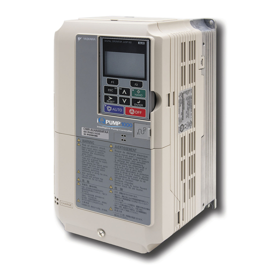
YASKAWA iQpump1000 Setup Procedure
With seametrics ag2000 flow meter
Hide thumbs
Also See for iQpump1000:
- User manual (508 pages) ,
- Quick start manual (356 pages) ,
- Installation & start?up manual (114 pages)
Advertisement
Technical Tip:
iQPump1000 Setup Procedure for Use with Seametrics AG2000 Flow Meter
Product(s):
iQpump1000
SUMMARY
This Technical Tip provides an example set-up for a Yaskawa iQpump1000 drive and a
Seametrics AG2000 Flow Meter.
Features of this system example:
Display flow rate
Check for high or low flow rates and provide a digital output/alarm/fault
Display accumulation of flow over time (volume)
Provide a digital output/alarm/fault for high accumulation totals
Provide constant pressure system
Limit flow rate to 500 gallons per minute (GPM) to avoid pumping off the well
Limit accumulation to 100,000 gallons per day (GPD)
Figure 1: Example System Overview
TN.iQp.04 ©2016 - Yaskawa America, Inc.
Revision 1 - 2016-04
Doc. No.
TN.iQp.04
Page 1 of 10
Advertisement
Table of Contents

Subscribe to Our Youtube Channel
Related Manuals for YASKAWA iQpump1000


Summary of Contents for YASKAWA iQpump1000
- Page 1 Doc. No. TN.iQp.04 SUMMARY This Technical Tip provides an example set-up for a Yaskawa iQpump1000 drive and a Seametrics AG2000 Flow Meter. Features of this system example: Display flow rate Check for high or low flow rates and provide a digital output/alarm/fault ...
-
Page 2: System Components
Technical Tip: iQPump1000 Setup Procedure for Use with Seametrics AG2000 Flow Meter Product(s): iQpump1000 Doc. No. TN.iQp.04 SYSTEM COMPONENTS Component Description iQpump1000 Drive Available models: CIMR-PWA 200 V Class: 3/4 to 175 HP ND CIMR-PWA 400 V Class: 3/4 to 1000 HP ND CIMR-PWA 600 V Class: 2 to 250 HP ND... - Page 3 Install the iQpump1000: Follow the instructions in TOEPYAIP1W02 iQpump1000 Installation & Start-up Guide provided in product packaging. Mechanically install the Seametrics AG2000 flow meter according to manufacturer’s instructions. Route shielded signal cable from the meter to the iQpump1000 I/O terminals . *Install pressure transducer if used.
-
Page 4: Step 1 - Make Electrical Connections
Product(s): iQpump1000 Doc. No. TN.iQp.04 STEP 1 – MAKE ELECTRICAL CONNECTIONS 1.1 Refer to Figure 2. Make electrical connections to the iQpump1000. Figure 2: Connection Diagram TN.iQp.04 ©2016 - Yaskawa America, Inc. Revision 1 - 2016-04 Page 4 of 10... - Page 5 Doc. No. TN.iQp.04 1.2 Install a pull-up resistor at iQpump1000 I/O terminals RP and 24V as shown in Figure 3. The pulse train output of the Seametrics AG2000 Flow Meter is a “sinking” type that requires a customer-supplied 10k Ohm resistor to condition the signal for the iQpump1000.
- Page 6 2.3 Start the iQpump1000 by pressing the HAND key on the JVOP-183. To set HAND SPEED, press ENTER and adjust P5-02 to set the speed to a known safe operating speed.
- Page 7 Technical Tip: iQPump1000 Setup Procedure for Use with Seametrics AG2000 Flow Meter Product(s): iQpump1000 Doc. No. TN.iQp.04 Figure 5: iQpump1000 Parameter U1-24 Flow Meter Output Signal Display 60 Hz Signal 100 Hz Signal (Higher flow rate example) 2.6 Alternate Method for Flow Meter Signal Verification (if multi-meter is not available) Use an analog GPM gauge in proximity to the flow meter, to find flow rate.
-
Page 8: Step 3 - Parameter Settings
Refer to the iQpump1000 User Manual TOEPYAIP1W01 for details about Pre-Charge and Loss of Prime. Note: In this example, the iQPump1000 drive will shut down and require resetting if the system reaches the setting level set in parameter P6-17. Table 1. iQPump1000 Parameter Settings for Seametrics AG2000-300 Meter (Example) - Page 9 Requires user reset after fault. Set parameter P6-19=2 to cause a fault if limit set in P6-17 is reached. High Flow Sel Monitor Parameters 3.3 View iQPump1000 monitor parameters, U1-83 through U1-87, to find current system flow rate and accumulation levels during system operation. Table 2. Monitor Parameters Name...
-
Page 10: Troubleshooting
Technical Tip: iQPump1000 Setup Procedure for Use with Seametrics AG2000 Flow Meter Product(s): iQpump1000 Doc. No. TN.iQp.04 Reading Accumulation: Monitors U1-84 to U1-87 3.4 Refer to Table 3. Observe Monitors U1-84 to U1-87 to build digits for total accumulation. Table 3. Example Accumulation Readings - iQpump1000 Display Monitor No.
Need help?
Do you have a question about the iQpump1000 and is the answer not in the manual?
Questions and answers