YASKAWA iQpump1000 Installation & Start?Up Manual
Intelligent pump controller
Hide thumbs
Also See for iQpump1000:
- User manual (508 pages) ,
- Quick start manual (356 pages) ,
- Setup procedure (10 pages)
Table of Contents
Advertisement
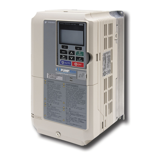
iQpump1000 AC Drive
Intelligent Pump Controller
Installation & Start-Up Guide
Type: CIMR-PW A
Models: 200 V Class: 3/4 to 175 HP ND
400 V Class: 3/4 to 1000 HP ND
600 V Class: 2 to 250 HP ND
To properly use the product, read this manual thoroughly and retain
for easy reference, inspection, and maintenance. Ensure the end user
receives this manual.
MANUAL NO. TOEP YAIP1W 02E
PUBLISHED MARCH 2017
REVISION <5>
DRIVE SOFTWARE PRG: 8554
Advertisement
Table of Contents

Related Manuals for YASKAWA iQpump1000


Summary of Contents for YASKAWA iQpump1000
- Page 1 AC Drive Intelligent Pump Controller Installation & Start-Up Guide Type: CIMR-PW A Models: 200 V Class: 3/4 to 175 HP ND 400 V Class: 3/4 to 1000 HP ND 600 V Class: 2 to 250 HP ND To properly use the product, read this manual thoroughly and retain for easy reference, inspection, and maintenance.
- Page 2 Every precaution has been taken in the preparation of this manual. Yaskawa assumes no responsibility for errors or omissions. Neither is any liability assumed for damages resulting from the use of the information contained in this publication.
-
Page 3: Table Of Contents
Installation & Start-up Guide PREFACE.........................4 RECEIVING......................11 MECHANICAL INSTALLATION................14 ELECTRICAL INSTALLATION................19 START-UP PROGRAMMING AND OPERATION..........44 TROUBLESHOOTING....................74 DRIVE SPECIFICATIONS..................85 PARAMETER TABLE....................87 STANDARDS COMPLIANCE................98 YASKAWA TOEP YAIP1W 02E YASKAWA AC Drive - iQpump1000 Installation & Start-up Guide... -
Page 4: Preface
• When ordering a new copy of the manual due to damage or loss, contact your Yaskawa representative or the nearest Yaskawa sales office and provide the manual number shown on the front cover. - Page 5 Do not attempt to modify or alter the drive in any way not explained in this manual. Failure to comply could result in death or serious injury. Yaskawa is not responsible for any modification of the product made by the user. This product must not be modified. Do not allow unqualified personnel to use equipment.
- Page 6 Do not carry the drive by the front cover. Failure to comply may result in minor or moderate injury from the main body of the drive falling. YASKAWA TOEP YAIP1W 02E YASKAWA AC Drive - iQpump1000 Installation & Start-up Guide...
- Page 7 When running more than one motor in parallel from a single drive, the capacity of the drive should be larger than [total motor rated current × 1.1]. YASKAWA TOEP YAIP1W 02E YASKAWA AC Drive - iQpump1000 Installation & Start-up Guide...
- Page 8 Yaskawa offers protective designs for drives that must be used in areas subjected to oil mist and excessive vibration. Contact Yaskawa or your Yaskawa agent for details.
- Page 9 Make sure that lubrication is sufficient within the entire speed range to avoid machine damage. Note that operation above the rated speed can increase the noise generated by the machine. YASKAWA TOEP YAIP1W 02E YASKAWA AC Drive - iQpump1000 Installation & Start-up Guide...
- Page 10 Customers who intend to use the product described in this manual for devices or systems relating to transportation, health care, space aviation, atomic power, electric power, or in underwater applications must first contact their Yaskawa representatives or the nearest Yaskawa sales office.
-
Page 11: Receiving
B – Software version F – Output specifications C – Enclosure type G – Input specifications D – Serial number H – AC drive model Figure i.3 Nameplate Information Example YASKAWA TOEP YAIP1W 02E YASKAWA AC Drive - iQpump1000 Installation & Start-up Guide... - Page 12 2A0081 22 (30) 2A0110 30 (40) 2A0138 37 (50) 2A0169 45 (60) 2A0211 55 (75) 2A0250 75 (100) 2A0312 90 (125) 2A0360 110 (150) 2A0415 110 (175) YASKAWA TOEP YAIP1W 02E YASKAWA AC Drive - iQpump1000 Installation & Start-up Guide...
- Page 13 5A0041 30 (40) 5A0052 37 (50) 5A0062 45 (60) 5A0077 55 (75) 5A0099 75 (100) 5A0125 90 (125) 5A0145 110 (150) 5A0192 160 (200) 5A0242 185 (250) YASKAWA TOEP YAIP1W 02E YASKAWA AC Drive - iQpump1000 Installation & Start-up Guide...
-
Page 14: Mechanical Installation
Failure to comply may damage the drive due to improper cooling. Figure i.4 Correct Installation Orientation NOTICE: Install the drive upright as specified in the manual. Failure to comply may damage the drive due to improper cooling. YASKAWA TOEP YAIP1W 02E YASKAWA AC Drive - iQpump1000 Installation & Start-up Guide... - Page 15 Align the tops of the drives when installing drives of different heights in the same enclosure panel. Leave space between the tops and bottoms of stacked drives for easier cooling fan replacement. YASKAWA TOEP YAIP1W 02E YASKAWA AC Drive - iQpump1000 Installation & Start-up Guide...
- Page 16 When vertical suspension of the drive is required in an enclosure panel, change the orientation of the eye bolts for these models by turning the eye bolts counterclockwise 90 degrees. YASKAWA TOEP YAIP1W 02E YASKAWA AC Drive - iQpump1000 Installation & Start-up Guide...
- Page 17 Lower the drive when ready to install in the enclosure panel. Stop lowering the drive when it is near the floor then begin lowering the drive again very slowly until the drive is placed correctly. YASKAWA TOEP YAIP1W 02E YASKAWA AC Drive - iQpump1000 Installation & Start-up Guide...
- Page 18 Mechanical Installation Drive Dimensions NOTICE Refer to the iQpump1000 Drive User Manual TOEP YAIP1W 01 for IP20/NEMA 1, UL Type 1 and IP00/Open Chassis dimensions. The iQpump1000 Drive User Manual is posted on the Yaskawa website, www.yaskawa.com. YASKAWA TOEP YAIP1W 02E YASKAWA AC Drive - iQpump1000 Installation & Start-up Guide...
-
Page 19: Electrical Installation
NOTICE: Do not connect AC control circuit ground to drive enclosure. Improper drive grounding can cause control circuit malfunction. Note: The minimum load for the relay outputs M1-M2, M3-M4, MA-MB-MC, and MD-ME-MF is 10 mA. YASKAWA TOEP YAIP1W 02E YASKAWA AC Drive - iQpump1000 Installation & Start-up Guide... - Page 20 E (G) Transducer - Supply (max. 150 mA) control circuit terminal shielded line twisted-pair shielded line main circuit terminal Figure i.12 Drive Standard Connection Diagram (example: model 2A0040) YASKAWA TOEP YAIP1W 02E YASKAWA AC Drive - iQpump1000 Installation & Start-up Guide...
- Page 21 (L5-02 = 0, default). Failure to comply will prevent the automatic fault restart function from working properly. YASKAWA TOEP YAIP1W 02E YASKAWA AC Drive - iQpump1000 Installation & Start-up Guide...
- Page 22 Three-Phase 600 V Class Models 5A0041, 5A0052 B1 B2 Relay DC link Current choke sensor R/L1 U/T1 S/L2 V/T2 T/L3 W/T3 – Control Gate board Operator board Figure i.14 Connecting Main Circuit Terminals YASKAWA TOEP YAIP1W 02E YASKAWA AC Drive - iQpump1000 Installation & Start-up Guide...
- Page 23 Current DC link choke sensor R/L1 U/T1 S/L2 V/T2 T/L3 W/T3 – 24 V Control Power Gate board Operator board Supply Figure i.16 Connecting Main Circuit Terminals YASKAWA TOEP YAIP1W 02E YASKAWA AC Drive - iQpump1000 Installation & Start-up Guide...
- Page 24 Alternate branch circuit protection devices are also listed in this manual. Refer to Factory Recommended Branch Circuit Protection on page 98 for details. YASKAWA TOEP YAIP1W 02E YASKAWA AC Drive - iQpump1000 Installation & Start-up Guide...
- Page 25 NOTICE: If a fuse is blown or an Ground Fault Circuit Interrupter (GFCI) is tripped, check the wiring and the selection of peripheral devices to identify the cause. Contact Yaskawa before restarting the drive or the peripheral devices if the cause cannot be identified.
- Page 26 Refer to Closed-Loop Crimp Terminal Size on page for closed-loop crimp terminal recommendations. The wire gauges listed in the following tables are Yaskawa recommendations. Refer to local codes for proper wire gauge selections. YASKAWA TOEP YAIP1W 02E YASKAWA AC Drive - iQpump1000 Installation & Start-up Guide...
- Page 27 ⊖, ⊕1, ⊕2 – 4 to 3 2A0069 2.7 to 3.0 B1, B2 – 8 to 6 (23.9 to 26.6) 5.4 to 6.0 6 to 4 (47.8 to 53.1) YASKAWA TOEP YAIP1W 02E YASKAWA AC Drive - iQpump1000 Installation & Start-up Guide...
- Page 28 ⊖, ⊕1 – 250 to 600 2A0360 18 to 23 ⊕3 – 3/0 to 600 (159 to 204) 32 to 40 1 to 350 (283 to 354) YASKAWA TOEP YAIP1W 02E YASKAWA AC Drive - iQpump1000 Installation & Start-up Guide...
- Page 29 – 10 to 6 4A0031 2.7 to 3.0 B1, B2 – 10 to 8 (23.9 to 26.6) 5.4 to 6.0 <2> 10 to 8 (47.8 to 53.1) YASKAWA TOEP YAIP1W 02E YASKAWA AC Drive - iQpump1000 Installation & Start-up Guide...
- Page 30 U/T1, V/T2, W/T3 2 to 300 18 to 23 ⊖, ⊕1 – 1 to 250 4A0208 (159 to 204) ⊕3 – 3 to 3/0 4 to 300 YASKAWA TOEP YAIP1W 02E YASKAWA AC Drive - iQpump1000 Installation & Start-up Guide...
- Page 31 When connecting peripheral devices or options to terminals ⊖, ⊕1, ⊕3, B1, and B2, refer to the instruction manual for each device. For Note: more information, contact Yaskawa or your nearest sales representative. YASKAWA TOEP YAIP1W 02E YASKAWA AC Drive - iQpump1000 Installation & Start-up Guide...
- Page 32 6.0 to 10 2.7 to 3.0 B1, B2 – (10 to 8) (23.9 to 26.6) 6.0 to 10 5.4 to 6.0 (10 to 6) (47.8 to 53.1) YASKAWA TOEP YAIP1W 02E YASKAWA AC Drive - iQpump1000 Installation & Start-up Guide...
- Page 33 (10 to 4/0) 35 to 95 18 to 23 ⊖, ⊕1 5A0099 – (2 to 4/0) (159 to 204) 25 to 95 ⊕3 – (4 to 4/0) YASKAWA TOEP YAIP1W 02E YASKAWA AC Drive - iQpump1000 Installation & Start-up Guide...
- Page 34 NOTICE: Do not connect phase-advancing capacitors or LC/RC noise filters to the output circuits. Failure to comply could result in damage to the drive, phase-advancing capacitors, LC/RC noise filters or ground fault circuit interrupters. YASKAWA TOEP YAIP1W 02E YASKAWA AC Drive - iQpump1000 Installation & Start-up Guide...
- Page 35 WARNING! Sudden Movement Hazard. Confirm the drive I/O signals and external sequence before starting test run. Setting parameter A1-03 may change the I/O terminal function automatically from the factory setting. Failure to comply may result in death or serious injury. YASKAWA TOEP YAIP1W 02E YASKAWA AC Drive - iQpump1000 Installation & Start-up Guide...
- Page 36 Fault Relay 30 Vdc, 10 mA to 1 A; 250 Vac, 10 mA to 1 A N.C. output Output Minimum load: 5 Vdc, 10 mA Fault output common YASKAWA TOEP YAIP1W 02E YASKAWA AC Drive - iQpump1000 Installation & Start-up Guide...
- Page 37 S1 S2 S3 S4 S5 S6 S7 S8 SN SC SP S1 S2 S3 S4 S5 S6 S7 S8 SN SC SP MA MB MC Figure i.20 Control Circuit Terminal Arrangement YASKAWA TOEP YAIP1W 02E YASKAWA AC Drive - iQpump1000 Installation & Start-up Guide...
- Page 38 Prepare the ends of the control circuit wiring as shown in Figure i. Refer to Wire Gauges on page Connect control wires as shown in Figure i.21 Figure i.22. YASKAWA TOEP YAIP1W 02E YASKAWA AC Drive - iQpump1000 Installation & Start-up Guide...
- Page 39 NOTICE: The analog signal wiring between the drive and the operator station or peripheral equipment should not exceed 50 meters when using an analog signal from a remote source to supply the frequency reference. Failure to comply could result in poor system performance. YASKAWA TOEP YAIP1W 02E YASKAWA AC Drive - iQpump1000 Installation & Start-up Guide...
- Page 40 V (top position) Voltage input (-10 to +10 V or 0 to 10 V) I (bottom position) Current input (4 to 20 mA or 0 to 20 mA) YASKAWA TOEP YAIP1W 02E YASKAWA AC Drive - iQpump1000 Installation & Start-up Guide...
- Page 41 Block Block 24V Power Supply 24V Power Supply Transducer Supply Common Signal 4-20 mA Transducer (typical) Signal 0-10 Vdc (typical) Output Shield Shield E(G) E(G) Output YASKAWA TOEP YAIP1W 02E YASKAWA AC Drive - iQpump1000 Installation & Start-up Guide...
- Page 42 Set jumper S1 to the “I” position for the last iQpump drive on the network. All other iQpump drives should have S1 set to the “V” position. YASKAWA TOEP YAIP1W 02E YASKAWA AC Drive - iQpump1000 Installation & Start-up Guide...
- Page 43 H4-07 Terminal FM signal level selection 0: 0 to 10 Vdc 1: -10 to 10 Vdc 0 to 2 H4-08 Terminal AM signal level selection 2: 4 to 20 mA YASKAWA TOEP YAIP1W 02E YASKAWA AC Drive - iQpump1000 Installation & Start-up Guide...
-
Page 44: Start-Up Programming And Operation
Real-Time Clock Setting at Initial Power-up of a New Drive Setting the Real-time clock is required at power-up of a new HOA operator or after digital operator battery replacement. YASKAWA TOEP YAIP1W 02E YASKAWA AC Drive - iQpump1000 Installation & Start-up Guide... - Page 45 - PRMSET - PRG Maintenance Use the up and down arrow keys to scroll through display menu until parameter o4-17 appears. o4-17 = 0 Set time HOME DATA YASKAWA TOEP YAIP1W 02E YASKAWA AC Drive - iQpump1000 Installation & Start-up Guide...
- Page 46 Setting 2: Reset The Real-Time Clock data is cleared. A Clock Not Set alarm will occur until o4-17 is set to 1 and the Real-Time Clock is set. YASKAWA TOEP YAIP1W 02E YASKAWA AC Drive - iQpump1000 Installation & Start-up Guide...
- Page 47 Lit while the drive is in AUTO mode. AUTO HAND Light Lit while the drive is in HAND mode. HAND ALM LED Light Lit when the drive detects an alarm or error. YASKAWA TOEP YAIP1W 02E YASKAWA AC Drive - iQpump1000 Installation & Start-up Guide...
- Page 48 Function Key 2 → Pressing scrolls the cursor to the right. (F2) RESET Pressing resets the existing drive fault error. Monitor Pressing switches Monitor mode. YASKAWA TOEP YAIP1W 02E YASKAWA AC Drive - iQpump1000 Installation & Start-up Guide...
- Page 49 • When an alarm occurs. Flashing • When an oPE is detected. • When a fault or error occurs during Auto-Tuning. Normal operation (no fault or alarm). YASKAWA TOEP YAIP1W 02E YASKAWA AC Drive - iQpump1000 Installation & Start-up Guide...
- Page 50 <5> The Frequency Reference appears after the initial display that shows the product name. <6> The information that appears on the display will vary depending on the drive model. YASKAWA TOEP YAIP1W 02E YASKAWA AC Drive - iQpump1000 Installation & Start-up Guide...
- Page 51 1. Settings 6012 and 6013 are available in drive software versions PRG: 8552 and later. 2. Settings 6012 and 6013 are not available in drive models 4A0930 and 4A1200. YASKAWA TOEP YAIP1W 02E YASKAWA AC Drive - iQpump1000 Installation & Start-up Guide...
- Page 52 If a Run command is input to the drive but the frequency reference entered is 0 or below the minimum frequency, the RUN indicator LED on the digital operator will light and the STOP indicator will flash. YASKAWA TOEP YAIP1W 02E YASKAWA AC Drive - iQpump1000 Installation & Start-up Guide...
- Page 53 Current Input Input terminals, A1, A2, and A3 can accept a current input signal. Refer to Table i.21 for an example to set terminal A2 for current input. YASKAWA TOEP YAIP1W 02E YASKAWA AC Drive - iQpump1000 Installation & Start-up Guide...
- Page 54 If the frequency reference source is set for Option PCB (b1-01 = 3), but an option board is not installed, an oPE05 Operator Programming Error will be displayed on the digital operator and the drive will not run. YASKAWA TOEP YAIP1W 02E YASKAWA AC Drive - iQpump1000 Installation & Start-up Guide...
- Page 55 If b1-02 is set to 3, but an option board is not installed in CN5-A, an oPE05 operator programming error will be displayed on the digital operator and the drive will not run. YASKAWA TOEP YAIP1W 02E YASKAWA AC Drive - iQpump1000 Installation & Start-up Guide...
- Page 56 Speed Search Selection at Start Determines if Speed Search is automatically performed when a Run command is issued. Parameter Name Setting Range Default b3-01 Speed Search Selection at Start 0, 1 YASKAWA TOEP YAIP1W 02E YASKAWA AC Drive - iQpump1000 Installation & Start-up Guide...
- Page 57 Search 1 or 2 is already enabled by a digital input, the drive will start operating with Speed Search. Setting 1: Enabled This setting performs Speed Search when the Run command is entered. The drive begins running the motor after Speed Search is complete. YASKAWA TOEP YAIP1W 02E YASKAWA AC Drive - iQpump1000 Installation & Start-up Guide...
- Page 58 Acceleration time parameters always set the time to accelerate from 0 Hz to the maximum output frequency (E1-04). Deceleration time parameters always set the time to decelerate from maximum output frequency to 0 Hz. C1-01 and C1-02 are the default active accel/decel settings. YASKAWA TOEP YAIP1W 02E YASKAWA AC Drive - iQpump1000 Installation & Start-up Guide...
- Page 59 Multi-Step Speed Reference 3 – Through mode – Jog reference selection – Up command – Accel/decel time selection 1 – Down command – Baseblock command (N.O.) – Forward Jog – YASKAWA TOEP YAIP1W 02E YASKAWA AC Drive - iQpump1000 Installation & Start-up Guide...
- Page 60 Frequency detection 1 – Zero speed – Frequency detection 2 – Speed agree 1 – Drive ready – User-set speed agree 1 – DC bus undervoltage – YASKAWA TOEP YAIP1W 02E YASKAWA AC Drive - iQpump1000 Installation & Start-up Guide...
- Page 61 OLV control mode. Setting 42: Pressure Reached Note: 1. Setting available in drive software versions PRG: 8552 and later. 2. Setting not available in drive models 4A0930 and 4A1200. YASKAWA TOEP YAIP1W 02E YASKAWA AC Drive - iQpump1000 Installation & Start-up Guide...
- Page 62 Use both parameters to adjust the characteristics of the analog input signal to terminal A1. Name Setting Range Default H3-03 Terminal A1 Gain Setting -999.9 to 999.9% 100.0% H3-04 Terminal A1 Bias Setting -999.9 to 999.9% 0.0% YASKAWA TOEP YAIP1W 02E YASKAWA AC Drive - iQpump1000 Installation & Start-up Guide...
- Page 63 The input level is 0 to 20 mA. Negative input values by negative bias or gain settings will be limited to 0%. H3-10: Terminal A2 Function Selection Determines the function assigned to analog input terminal A2. Name Setting Range Default H3-10 Terminal A2 Function Selection 0 to 32 YASKAWA TOEP YAIP1W 02E YASKAWA AC Drive - iQpump1000 Installation & Start-up Guide...
- Page 64 Multi-Function Analog Output Terminal AM H4-08 0 to 2 Signal Level Selection Setting 0: 0 to 10 V Setting 1: -10 V to 10 V Setting 2: 4 to 20 mA YASKAWA TOEP YAIP1W 02E YASKAWA AC Drive - iQpump1000 Installation & Start-up Guide...
- Page 65 • Remote Drive Disable: When this function is active, the drive is unavailable to the iQpump MEMOBUS Network and will force the Home Screen text to show “Pump Off Network”. YASKAWA TOEP YAIP1W 02E YASKAWA AC Drive - iQpump1000 Installation & Start-up Guide...
- Page 66 Sets the delay time for waking the drive to prevent accidental wake up caused by erratic feedback. Parameter Name Setting Range Default P1-05 Start Level Delay Time 0 to 3600 s YASKAWA TOEP YAIP1W 02E YASKAWA AC Drive - iQpump1000 Installation & Start-up Guide...
- Page 67 When feedback rises above the level determined by P1-08 and P1-14, or when one or more of the conditions that enable low feedback detection are no longer true, the digital output will open. YASKAWA TOEP YAIP1W 02E YASKAWA AC Drive - iQpump1000 Installation & Start-up Guide...
- Page 68 Set this parameter prior to changing other parameters related to the Sleep Function, as internal scaling is based on P2-01. Parameter Name Setting Range Default P2-01 Sleep Level Type 0 to 4 YASKAWA TOEP YAIP1W 02E YASKAWA AC Drive - iQpump1000 Installation & Start-up Guide...
- Page 69 The drive will exit the pre-charge function early if the feedback rises above the P4-01 setting or if a Low Water digital input switch (H1-oo = 8F) deactivates. Pre-charge is useful to slowly fill or pressurize a system. YASKAWA TOEP YAIP1W 02E YASKAWA AC Drive - iQpump1000 Installation & Start-up Guide...
- Page 70 • The PID feedback satisfies both Pre-charge levels 1 and 2 (all must be true): Pre-charge timers P4-03 and P4-07 have NOT expired PID is enabled (b5-01 > 0). YASKAWA TOEP YAIP1W 02E YASKAWA AC Drive - iQpump1000 Installation & Start-up Guide...
- Page 71 If P4-12 is set greater than P1-06 (minimum Pump Speed), P4-12 will become the frequency lower limit. The drive PID control must be disabled (b5-01 = 0) for this function to work. Parameter Name Setting Range Default P4-12 Thrust Bearing Frequency 0.0 to E1-04 30.0 Hz YASKAWA TOEP YAIP1W 02E YASKAWA AC Drive - iQpump1000 Installation & Start-up Guide...
- Page 72 After performing a no-load test run, connect the motor and proceed to run the motor and load together. Checklist Before Operation • The motor should rotate in the proper direction. YASKAWA TOEP YAIP1W 02E YASKAWA AC Drive - iQpump1000 Installation & Start-up Guide...
- Page 73 • If the application permits running the load in the reverse direction, change the motor direction and the frequency reference while watching for abnormal motor oscillation or vibration. • Correct any problems that occur with hunting, oscillation, and other control-related issues. YASKAWA TOEP YAIP1W 02E YASKAWA AC Drive - iQpump1000 Installation & Start-up Guide...
-
Page 74: Troubleshooting
Troubleshooting NOTICE Refer to the iQpump1000 Drive User Manual TOEP YAIP1W 01 for information on Troubleshooting and complete product instructions necessary for proper installation, set-up, troubleshooting and maintenance. The iQpump1000 Drive Quick User Manual is posted on the Yaskawa website, www.yaskawa.com. - Page 75 Loss of Prime The pump has lost its prime. LOSUC Low Section Pressure Low Suction LOWFL Low Flow Low Flow LOWWL Low Water Level Low Water Level YASKAWA TOEP YAIP1W 02E YASKAWA AC Drive - iQpump1000 Installation & Start-up Guide...
- Page 76 The thermal sensor of the drive triggered overload protection. Overtorque Detection 1 The current has exceeded the value set for torque detection (L6-02) for longer than the allowable time (L6-03). YASKAWA TOEP YAIP1W 02E YASKAWA AC Drive - iQpump1000 Installation & Start-up Guide...
- Page 77 The current has fallen below the minimum value set for torque detection (L6-05) for longer than the allowable time (L6-06). Motor Underload The load has fallen below the underload curve defined in L6-14. Current Unbalance UnbC <1> Current flow has become unbalanced. YASKAWA TOEP YAIP1W 02E YASKAWA AC Drive - iQpump1000 Installation & Start-up Guide...
- Page 78 • The connection was lost after initial communication was established. • Assign a Run command frequency reference to the option. Serial Communication Transmission Error CALL Communication has not yet been established. YASKAWA TOEP YAIP1W 02E YASKAWA AC Drive - iQpump1000 Installation & Start-up Guide...
- Page 79 Low City Pressure Low City Pressure Low Feedback Level Alarm Low Feedback Low FB Sensed The feedback signal is too low. Low Suction Pressure Low Suction Pressure YASKAWA TOEP YAIP1W 02E YASKAWA AC Drive - iQpump1000 Installation & Start-up Guide...
- Page 80 • For 400 V class drives: approximately 820 V (740 V when E1-01 is less than 400) • For 600 V class drives: approximately 1040 V Pump Over Cycle R-DNE-So Remote Drive Disable YASKAWA TOEP YAIP1W 02E YASKAWA AC Drive - iQpump1000 Installation & Start-up Guide...
- Page 81 Use U1-18 to find parameters set outside the range. Multi-Function Input Selection Error oPE03 A contradictory setting is assigned to multi-function contact inputs H1-01 to H1-08. oPE04 Initialization Required, Term <–> Ctrl Chg YASKAWA TOEP YAIP1W 02E YASKAWA AC Drive - iQpump1000 Installation & Start-up Guide...
- Page 82 Er-03 STOP Button Input Er-04 Line-to-Line Resistance Error Er-05 No-Load Current Error Er-08 Rated Slip Error Er-09 Acceleration Error Er-11 Motor Speed Fault Er-12 Current Detection Error YASKAWA TOEP YAIP1W 02E YASKAWA AC Drive - iQpump1000 Installation & Start-up Guide...
- Page 83 MEMOBUS/Modbus test has finished normally. Mode Complete Pre Chg Mode Pre-charge 1 or 2 active. X indicates time left before pre-charge exits due to timers (P4-03 + P4-07). Exit in Xsec YASKAWA TOEP YAIP1W 02E YASKAWA AC Drive - iQpump1000 Installation & Start-up Guide...
- Page 84 Turn off the main power supply if the above methods do not reset the fault. Reapply power after the HOA keypad display has turned off. When an “SC” error occurs, contact Yaskawa or a Yaskawa agent before cycling the power to the drive. Note: If the Run command is present, the drive will disregard any attempts to reset the fault.
-
Page 85: Drive Specifications
Undervoltage Protection 400 V class: Stops when DC bus voltage falls below approx. 380 V 600 V class: Stops when DC bus voltage falls below approx. 475 V YASKAWA TOEP YAIP1W 02E YASKAWA AC Drive - iQpump1000 Installation & Start-up Guide... - Page 86 <10> Removing the top protective cover or bottom conduit bracket from an IP20/NEMA 1, UL Type 1 enclosure drive voids NEMA 1, UL Type 1 protection while maintaining IP20 conformity. This is applicable to models 2A0004 to 2A0211, 4A0002 to 4A0165, and 5A0003 to 5A0242. YASKAWA TOEP YAIP1W 02E YASKAWA AC Drive - iQpump1000 Installation & Start-up Guide...
-
Page 87: Parameter Table
Sets the integral time for the PID controller. Sets the maximum output possible from the b5-06 PID Output Limit entire PID controller as a percentage of the maximum output frequency. YASKAWA TOEP YAIP1W 02E YASKAWA AC Drive - iQpump1000 Installation & Start-up Guide... - Page 88 Sets the motor rated slip. Automatically set Upper Limit E2-02 Motor Rated Slip frequency. during Auto-Tuning. Motor No-Load Sets the no-load current for the motor. E2-03 Current Automatically set during Auto-Tuning. YASKAWA TOEP YAIP1W 02E YASKAWA AC Drive - iQpump1000 Installation & Start-up Guide...
- Page 89 Sets the level of the input value selected in H5-01 Drive Node Address H3-08 S+, S-. Cycle power for the setting to take Setting H3-06 when 0 V is input at terminal A3. effect. YASKAWA TOEP YAIP1W 02E YASKAWA AC Drive - iQpump1000 Installation & Start-up Guide...
- Page 90 4: KEB deceleration as long as CPU has power. 5: KEB deceleration to stop. Sets the Power Loss Ride-Thru time. Momentary Power L2-02 Enabled only when Loss Ride-Thru Time L2-01 = 1 or 3. YASKAWA TOEP YAIP1W 02E YASKAWA AC Drive - iQpump1000 Installation & Start-up Guide...
- Page 91 0: Drive only Ambient Temperature Enter the ambient temperature. This value P1-01 Pump Mode 1: Contactor lag L8-12 Setting adjusts the oL2 detection level. 3: MEMOBUS network YASKAWA TOEP YAIP1W 02E YASKAWA AC Drive - iQpump1000 Installation & Start-up Guide...
- Page 92 This parameter is internally lower limited to 0: Fault High Feedback the minimum pump speed (P1-06, P4-12, P1-13 1: Alarm Selection d2-02) when not set to 0.0. 2: Digital out only YASKAWA TOEP YAIP1W 02E YASKAWA AC Drive - iQpump1000 Installation & Start-up Guide...
- Page 93 Sets the time delay before the drive starts P3-07 frequency will be limited after lag pump is Anti-No-Flow after Staging Time P2-24 the increased deceleration rate after Anti- staged. Detection Time No-Flow is detected. YASKAWA TOEP YAIP1W 02E YASKAWA AC Drive - iQpump1000 Installation & Start-up Guide...
- Page 94 Sets the method for removing contactor Setting this parameter to 0.0 disables the De-Stage Selection pumps. P3-31 function. Mode 0: Last in, first out (LIFO) 1: First in, first out (FIFO) YASKAWA TOEP YAIP1W 02E YASKAWA AC Drive - iQpump1000 Installation & Start-up Guide...
- Page 95 2: Primer Pump Style 0: Full Screen Message 3: Screen Motor Starter 1: Home Monitor Text Lube Pump Active 0: Disabled P4-30 During Run 1: Active During Run YASKAWA TOEP YAIP1W 02E YASKAWA AC Drive - iQpump1000 Installation & Start-up Guide...
- Page 96 2: Feedback + Fout 3: Flow meter Sets the PID Setpoint when the “Multi PID Controller Q1-03 Setpoint 2” or "Alternate Multi Setpoint 2" Setpoint 3 digital input is closed. YASKAWA TOEP YAIP1W 02E YASKAWA AC Drive - iQpump1000 Installation & Start-up Guide...
- Page 97 Q5-04, Minimum Water Level Sleep Q4-05 delay after the water level drops below the Suction Pressure. Delay Time level set in Q4-04 before going to sleep. YASKAWA TOEP YAIP1W 02E YASKAWA AC Drive - iQpump1000 Installation & Start-up Guide...
-
Page 98: Standards Compliance
NOTICE: If a fuse is blown or a Ground Fault Circuit Interrupter (GFCI) is tripped, check the wiring and the selection of peripheral devices to identify the cause. Contact Yaskawa before restarting the drive or the peripheral devices if the cause cannot be identified. - Page 99 <1> FWP-50B 5A0004 <1> FWP-60B 5A0006 <1> FWP-60B 5A0009 <1> FWP-70B 5A0011 <1> FWP-100B 5A0017 <1> FWP-100B 5A0022 <1> FWP-125A 5A0027 <1> FWP-125A 5A0032 <1> FWP-175A 5A0041 YASKAWA TOEP YAIP1W 02E YASKAWA AC Drive - iQpump1000 Installation & Start-up Guide...
- Page 100 Verify the following installation conditions to ensure that other devices and machinery used in combination with this drive also comply with EMC guidelines. Install an EMC noise filter to the input side specified by Yaskawa for compliance with European standards. Place the drive and EMC noise filter in the same enclosure.
- Page 101 A – Braided shield cable C – Cable clamp (conductive) B – Metal panel Figure i.35 Ground Area Connect a DC link choke to minimize harmonic distortion. YASKAWA TOEP YAIP1W 02E YASKAWA AC Drive - iQpump1000 Installation & Start-up Guide...
- Page 102 F – Motor cable (braided shield cable, max. 10 m) Figure i.36 EMC Filter and Drive Installation for CE Compliance (Three-Phase 200 V / 400 V Class) YASKAWA TOEP YAIP1W 02E YASKAWA AC Drive - iQpump1000 Installation & Start-up Guide...
- Page 103 2A0110 to 2A0415, 4A0058 to 4A1200, and 5A0041 to 5A0242. Use only the tools recommended by the terminal manufacturer for crimping. Yaskawa recommends crimp terminals made by JST and Tokyo DIP (or equivalent) for the insulation cap.
- Page 104 350 × 2P 180-L12 100-066-688 YF-1 TD-327, 2A0415 TP-200 YET-300-1 TD-314 400 × 2P 200-L12 100-051-564 500 × 2P TD-328, 325-12 TP-325 100-051-277 TD-315 600 × 2P YASKAWA TOEP YAIP1W 02E YASKAWA AC Drive - iQpump1000 Installation & Start-up Guide...
- Page 105 TP-038 100-051-556 TD-212 1 × 2P TD-227, 3/0 × 2P 80-L10 TP-080 100-051-557 TD-214 YF-1 4A0208 YET-150-1 TD-228, R100-10 TP-100 100-051-269 TD-214 TD-229, R150-10 TP-150 100-051-272 TD-215 YASKAWA TOEP YAIP1W 02E YASKAWA AC Drive - iQpump1000 Installation & Start-up Guide...
- Page 106 3/0 × 8P 80-L12 TP-080 100-051-558 TD-312 TD-324, YF-1 4/0 × 8P 100-L12 TP-100 100-051-560 4A0930 TD-312 YET-300-1 250 × 8P TD-325, 150-L12 TP-150 100-051-562 TD-313 300 × 8P YASKAWA TOEP YAIP1W 02E YASKAWA AC Drive - iQpump1000 Installation & Start-up Guide...
- Page 107 NOTICE: If a fuse is blown or a Ground Fault Circuit Interrupter (GFCI) is tripped, check the wiring and the selection of the peripheral devices. Check the wiring and the selection of peripheral devices to identify the cause. Contact Yaskawa before restarting the drive or the peripheral devices if the cause cannot be identified.
- Page 108 <4> When using semiconductor fuses, Bussman FWH and FWP are required for UL compliance. Select FWH for 200 V Class and 400 V Class models and FWP fuses for 600 V models. YASKAWA TOEP YAIP1W 02E YASKAWA AC Drive - iQpump1000 Installation & Start-up Guide...
- Page 109 NOTICE: If a fuse is blown or an Ground Fault Circuit Interrupter (GFCI) is tripped, check the wiring and the selection of peripheral devices to identify the cause. Contact Yaskawa before restarting the drive or the peripheral devices if the cause cannot be identified.
- Page 110 Hot start (characteristics when an overload occurs during continuous operation at 100%) Motor current (%) E2-01 = 100% motor current Figure i.39 Motor Overload Protection Time YASKAWA TOEP YAIP1W 02E YASKAWA AC Drive - iQpump1000 Installation & Start-up Guide...
- Page 111 Standards Compliance This Page Intentionally Blank YASKAWA TOEP YAIP1W 02E YASKAWA AC Drive - iQpump1000 Installation & Start-up Guide...
- Page 112 Addition: Support for models 4A0930 and 4A1200. Sections for Keypad January 2014 <1> Operation, Start-up, Parameter Table, and Troubleshooting. Revision: Removed Parameter Setting Reference Table. July 2013 First Edition YASKAWA TOEP YAIP1W 02E YASKAWA AC Drive - iQpump1000 Installation & Start-up Guide...
- Page 114 Intelligent Pump Controller Installation & Start-Up Guide YASKAWA AMERICA, INC. 2121, Norman Drive South, Waukegan, IL 60085, U.S.A. Phone: 1-800-YASKAWA (927-5292) or 1-847-887-7000 Fax: 1-847-887-7310 http://www.yaskawa.com DRIVE CENTER (INVERTER PLANT) 2-13-1, Nishimiyaichi, Yukuhashi, Fukuoka, 824-8511, Japan Phone: 81-930-25-3844 Fax: 81-930-25-4369 http://www.yaskawa.co.jp...
Need help?
Do you have a question about the iQpump1000 and is the answer not in the manual?
Questions and answers