Sign In
Upload
Manuals
Brands
Euphonix Manuals
Music Mixer
System 5
Euphonix System 5 Digital Audio Mixing Manuals
Manuals and User Guides for Euphonix System 5 Digital Audio Mixing. We have
9
Euphonix System 5 Digital Audio Mixing manuals available for free PDF download: Operation Manual, Manual, Installation Manual, Brochure, Setup Manual, Application Note
Euphonix System 5 Manual (228 pages)
Digital Audio Mixing System
Brand:
Euphonix
| Category:
Other
| Size: 22 MB
Table of Contents
Table of Contents
5
List of Figures
14
Chapter 1: Introduction
19
How to Use this Manual
20
System 5 Hardware
22
System 5 Hardware Diagram
22
System 5 Logs Accessible through Windows Explorer
23
System 5 Startup Sequence
24
Chapter 2: New Features in Emix Version 3.0
25
Chapter 3: Quickstart to Common Tasks
27
Connect and Play a CD
27
New Title Dialog
27
Sources Page in Patchnet
28
Connect and Monitor a Microphone
29
Cabling
29
Microphone Assignment in Sources
30
Chapter 4: Emix Application
32
Directory
32
Projects
32
Projects Window
33
Titles
34
Titles Window
34
New Title Dialog
35
Mixes
36
Mixes Window
37
Operations on Current Title and MIX
38
File Operations Buttons for Current Title
38
Title Defaults
39
Updating Title Defaults Warning
39
Destinations Normalled
40
Patchnet
42
Simplified MADI Routing Diagram
42
Console I/O
43
Console I/O a and B Inputs Window
43
Destinations and Sources
44
Cabling
44
Bottom of Console I/O Window
44
Patching Examples
45
Sources Window
46
Selecting Destination Channels
47
Mics Patched to Channels
48
MIX Bus Send/Return
49
Nuendo and Mics Patched
49
MIX Bus Send and Return
49
Monitor Patching
50
Solo Bus and Utility Patching
50
Talkback Signal Patching
50
Busses
51
MIX Bus Window with Law Palette
51
Group Bus Window
51
Law Palette
52
Law Palette Formats
52
Externals
53
System
53
Mixer Model
53
Mixer Models
54
Euphonix Control Panel
55
Euphonix Control Panel DF66 Properties Base Rate Menu
56
Euphonix Control Panel DF66 Properties MADI Menu
57
Folddown
58
Folddown Window
58
Diagnostics
59
Diagnostics Window
59
Masters
60
Conform
60
Events
60
System 5 Logo
60
Auto Failover
60
Control Panel
60
View Log
60
Chapter 5: CM401T Master Section
61
CM401T Master Module
61
Monitoring
62
Monitor Source Selection
62
Monitoring Matrix
62
Monitor Controls and Mond Source Panel
63
MIX Section and Aux Send Format
64
Control Room Monitor Controls
64
CR Output Controls and Control Room Output Panel
65
Sls/Cue Monitor Outputs
67
Communications
68
Talkback
69
Comms:talkback Panels
69
Listenback
70
Comms:listenback Panel
70
Oscillator/Slate
71
Comms:slate/Osc Panel
72
Quick Access Communications Panels
73
Quick Access Communication Panels
73
Solo
74
Solo Mode
74
Master solo Section (Top-Left) and solo Control Panel
74
Solo Level
75
Solo Clear
75
Intercancel, Momentary, and Sum
75
Solo Speaker Selection
75
Solo Speaker DIM
75
Solo-Safe
76
Backstop PFL
76
Meters
77
Meters Panel
77
Channel Meter with Dynamics Gain Reduction Meter on Right
77
Meter Presets and Meter Configuration Panels
78
Master Section Meters
80
Master Section Meters Showing 5.1-Channel CR and Aux Busses 1-8
80
Chapter 6: CM402T Center Section
81
CM402T Center Section
81
Channel Select Panel
83
Knobset Panels
84
Knobset Control Panel
84
Center Panel Knobsets
84
Knobset Control Panel
85
Center Panel Knobset Presets
85
Bus Routing Panel
86
Grp Route
86
MIX Route
86
Grp Section
86
Track Arming
86
Chapter 7: Busses and Bus Masters
87
Introduction to System 5 Busses
87
Bus Master Functions
88
CM401T Center Section with Bus Master Strip
88
Aux, Grp, and MIX Masters
89
Bus Lock
89
Mon Lock
89
All Key
89
MIX Bus
89
MIX Bus Master (Left) and Individual Bus (Right) Displays
90
Group and Aux Busses
91
Configuring Aux Busses
91
Aux Bus Settings
91
Bus Master Inserts
94
MIX and Group Bus Setup
94
Bus Processing
94
Bus Processing Configuration
94
Chapter 8: Channels and Strips
95
Strips
95
The Strip with Block Diagram for Main/Swap Channels and Meter/Status Display
96
Map Channels and Control Groups to Strips
97
Strip Controls During Channel Assignment
97
Channel Assign Panel
98
Busses Assign Panel
99
Input Names or Channel Number
100
Strip Utilities
101
Strip Config Panel, P a G E S 1 a N D 2 O F 4
101
Center Section Select Panel
103
Strip Config Panel, P a G E S 3 a N D 4 O F 4
105
Strip Config Panel, Page 3 and 4 of
105
Channel Control Features
107
Channel Name
107
Function Keys
107
Rotary Knobs
107
Rotary Knob Controls
107
Touch-Sensitive Fader and Controls
108
Fader Controls
108
Wave Key
109
All Mode
109
Link Key
110
Copy and Paste
110
Talk [S5B Only]
110
Channel Process Order and Patch Points
111
Changing Processor Order and Patch Points
111
Channel Patch Points
112
Channel Processor Order
113
Insert Point
113
Changing Processor Order
113
Channel Processing Functions
114
Inputs
114
Input a (Left) and Signal Processing In/Out (Right) Knobsets
114
Stereo Controls
116
Dynamics
117
Dynamics Knobset
118
Expander/Gate, Compressor, and Sidechain/Filters Knobset
119
Equalizers and Filters
121
EQ and Filters Knobsets
121
Aux Sends
123
Aux Send Knobset and Pre/Post Config
124
Pan
126
Pan Knobsets
126
Pan Graph
128
Channel Mixing Functions
129
Group Bus Routing
129
GRP and MIX Route Switches
129
MIX Bus Routing
130
MIX Minus [S5B Only]
130
MIX Minus Knobset and Signal Flow
131
Chapter 9: Linking [S5P Only]
132
Creating a Link
132
Modifying and Clearing a Link
133
Link Suspend
133
Links and Automation
133
Joystick Linking
134
Setting Joystick Links
134
Clearing a Joystick Link
135
Joystick Absolute Vs. Relative Control
135
Chapter 10:Control Groups and Multi Format Masters
136
Control Groups
136
Create Control Group
137
Groups Panel
137
Assign Control Group to Strip
138
Modify Control Group
138
Name Control Group
138
Clear Control Group
138
Coalesce Control Group
139
Multi Format Masters
139
Masters Screen
139
Spill Area
140
Control Groups or Multi Format Masters
141
Chapter 11: Layouts and Snapshots
142
Layouts
143
Create a New Layout
143
Layouts Panel
144
Recall a Layout
145
Modify a Layout
145
Rename a Layout
145
Delete a Layout
146
Snapshots
146
Create a New Snapshot
146
Snapshots Panel
147
Recall a Snapshot
148
Update Snapshot
148
Rename a Snapshot
149
Delete a Snapshot
149
Scene Automation
149
CM401T Scene List
149
Scene List
150
CM401T Scene Automation Edit Page
150
Scenes
151
Scene Menu
151
Chapter 12: Machine Control [S5P Only]
153
Machine Control Panel
153
Transport Controls
154
Locate Controls
155
Time Displays
155
Locator Controls
155
Locate Registers Panel
156
Store Locate Value to a Register
157
Store Current Value to a Register
157
Locate Key
158
Return Key
158
Title Start
158
Cue Points
158
Track Arming
160
Machine Setup Panel
160
Record in Motion
161
Track Arm in Motion
161
On Transport Stop
161
Arm While Stopped
161
TC Lock
161
Auto Punch: Locate
162
Chapter 13: GPI/O Event System
163
Input Types
164
GP Input Types, Settings, and Activation Values
164
Output Types
165
GP Output Types, Settings, and Activation Values
165
Logical Operators
166
Event Configuration Display
166
Logical Operators Used for GPI/O Event Processing
166
Event List
167
Input
167
Event Configuration Window
167
Output
168
Deleting Events
168
Add Input Event Dialog
168
GPI Examples
169
Move a Fader to Turn off the Floor Monitors
169
Move a Fader to Turn on the Floor Monitors
170
Move a Fader to Start a Cart Machine
171
Move a Fader to Stop a Cart Machine
172
Video Switcher Turns a Specific Camera MIC Channel on
173
Video Switcher Turns a Specific Camera MIC Channel off
174
Audio Follow Video
175
Audio Follow Video Configuration
175
Add Input Event Dialog
176
Input Event Properties
176
Add Output Event Dialog
177
Output Event Properties
177
Advertisement
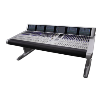
Euphonix System 5 Operation Manual (228 pages)
Digital Audio Mixing System
Brand:
Euphonix
| Category:
Music Mixer
| Size: 11 MB
Table of Contents
Important Safety Instructions
3
Table of Contents
5
List of Figures
13
Chapter 1: Introduction
19
How to Use this Manual
20
System 5 Hardware
22
System 5 Hardware Diagram
22
System 5 Startup Sequence
24
Chapter 2: New Features in Emix Version 2.9
25
Chapter 3: Quickstart to Common Tasks
27
Connect and Play a CD
27
New Title Dialog
27
Device Outputs Page in Patchnet
28
Connect and Monitor a Microphone
29
Cabling
29
Microphone Assignment in Device Outputs
30
Chapter 4: Emix Application
33
Directory
33
Projects
33
Projects Window
34
Titles
35
Titles Window
35
New Title Dialog
36
Mixes
37
Mixes Window
38
Operations on Current Title and MIX
39
File Operations Buttons for Current Title
39
Title Defaults
40
Updating Title Defaults Warning
40
Device Inputs Normalled
41
Patchnet
43
Simplified MADI Routing Diagram
43
Console I/O
44
Console I/O a and B Inputs Window
44
Device Inputs and Outputs
45
Cabling
45
Bottom of Console I/O Window
45
Patching Examples
46
Device Outputs Window
47
Selecting Destination Channels
48
Mics Patched to Channels
49
MIX Bus Send/Return
50
And Mics Patched
50
MIX Bus Send and Return
50
Monitor Patching
51
Solo Bus and Utility Patching
51
Talkback Signal Patching
51
Busses
52
MIX Bus Window with Law Palette
52
Group Bus Window
52
Law Palette
53
Law Palette Formats
53
Externals
54
System
54
Mixer Model
54
Mixer Models
55
Folddown
57
Folddown Window
57
Diagnostics
58
Diagnostics Window
58
Masters
59
Conform
59
Events
59
System 5 Logo
59
Chapter 5: CM401 Master Section
61
CM401 Master Module
61
Monitoring
62
Monitor Source Selection
62
Monitoring Matrix
62
Monitor Controls and Mond Source Panel
63
MIX Section and Aux Send Format
64
Control Room Monitor Controls
64
CR Output Controls and Control Room Output Panel
65
Sls/Cue Monitor Outputs
67
Communications
68
Talkback
69
Comms:talkback Panels
69
Listenback
70
Comms:listenback Panel
70
Oscillator/Slate
71
Comms:slate/Osc Panel
72
Quick Access Communications Panels
73
Quick Access Communication Panels
73
Solo
74
Solo Mode
74
Master solo Section (Top-Left) and solo Control Panel
74
Solo Level
75
Solo Clear
75
Intercancel, Momentary, and Sum
75
Solo Speaker Selection
75
Solo Speaker DIM
75
Solo-Safe
76
Backstop PFL
76
Meters
77
Meters Panel
77
Channel Meter with Dynamics Gain Reduction Meter on Right
77
Meter Presets and Meter Configuration Panels
78
Master Section Meters
80
Master Section Meters Showing 5.1-Channel CR and Aux Busses 1-8
80
Chapter 6: CM402 Center Section
81
CM402 Center Section
82
Channel Select Panel
83
Knobset Panels
84
Center Panel Knobsets
84
Knobset Control Panel
85
Center Panel Knobset Presets
85
Bus Routing Panel
86
Grp Route
86
MIX Route
86
Grp Section
86
Track Arming
86
Chapter 7: Busses and Bus Masters
87
Introduction to System 5 Busses
87
Bus Master Functions
88
CM401 Center Section with Bus Master Strip
88
Aux, Grp, and MIX Masters
89
Bus Lock
89
Mon Lock
89
All Key
89
MIX Bus
89
MIX Bus Master (Left) and Individual Bus (Right) Displays
90
Group and Aux Busses
91
Configuring Aux Busses
91
Aux Bus Settings
91
Set Unity
92
Toggle Stereo
92
Bus Master Inserts
94
MIX and Group Bus Setup
94
Chapter 8: Channels and Strips
95
Strips
95
The Strip with Block Diagram for Main/Swap Channels and Meter/Status Display
96
Map Channels and Control Groups to Strips
97
Strip Controls During Channel Assignment
97
Channel Assign Panel
98
Input Names or Channel Number
99
Strip Utilities
100
Strip Config Panel
100
Center Section Select Panel
102
Channel Control Features
104
Channel Name
104
Function Keys
104
Rotary Knobs
104
Rotary Knob Controls
104
Touch-Sensitive Fader and Controls
105
Fader Controls
105
Wave Key
106
All Mode
106
Link Key
106
Copy and Paste
107
Channel Process Order and Patch Points
108
Channel Processor Order and Patch Points
108
Channel Patch Points
109
Channel Processor Order
110
Insert Point
110
Changing Processor Order
110
Channel Processing Functions
111
Inputs
111
Input a (Left) and Signal Processing In/Out (Right) Knobsets
111
Stereo Controls
113
Dynamics
114
Dynamics Knobset
115
Expander/Gate, Compressor, and Sidechain/Filters Knobset
116
Equalizers and Filters
118
EQ and Filters Knobsets
118
Aux Sends
120
Aux Send Knobset and Pre/Post Config
121
Pan
123
Pan Knobsets
123
Pan Graph
125
Channel Mixing Functions
126
Group Bus Routing
126
GRP and MIX Route Switches
126
MIX Bus Routing
127
Chapter 9: Linking
129
Creating a Link
129
Modifying and Clearing a Link
130
Link Suspend
130
Links and Automation
130
Joystick Linking
131
Setting Joystick Links
131
Clearing a Joystick Link
132
Joystick Absolute Vs. Relative Control
132
Chapter 10:Control Groups and Multi Format Masters
133
Control Groups
133
Create Control Group
134
Groups Panel
134
Assign Control Group to Strip
135
Modify Control Group
135
Name Control Group
135
Clear Control Group
135
Coalesce Control Group
136
Multi Format Masters
136
Masters Screen
136
Spill Area
137
Control Groups or Multi Format Masters
138
Chapter 11: Layouts and Snapshots
139
Layouts
140
Create a New Layout
140
Layouts Panel
141
Recall a Layout
142
Modify a Layout
142
Rename a Layout
142
Delete a Layout
143
Snapshots
143
Create a New Snapshot
143
Snapshots Panel
144
Recall a Snapshot
145
Update Snapshot
145
Rename a Snapshot
146
Delete a Snapshot
146
Chapter 12: Machine Control
147
Machine Control Panel
147
Transport Controls
148
Locate Controls
149
Time Displays
149
Locator Controls
149
Locate Registers Panel
150
Store Locate Value to a Register
151
Store Current Value to a Register
151
Locate Key
152
Return Key
152
Title Start
152
Cue Points
152
Track Arming
154
Machine Setup Panel
154
Record in Motion
155
Track Arm in Motion
155
On Transport Stop
155
Arm While Stopped
155
TC Lock
155
Chapter 13: GPI/O Event System
157
Input Types
158
GP Input Types, Settings, and Activation Values
158
Output Types
159
GP Output Types, Settings, and Activation Values
159
Logical Operators
160
Event Configuration Display
160
Logical Operators Used for GPI/O Event Processing
160
Event List
161
Input
161
Event Configuration Window
161
Output
162
Deleting Events
162
Add Input Event Dialog
162
GPI Examples
163
Move a Fader to Turn off the Floor Monitors
163
Move a Fader to Turn on the Floor Monitors
164
Move a Fader to Start a Cart Machine
165
Move a Fader to Stop a Cart Machine
166
Video Switcher Turns a Specific Camera and Channel on
167
Video Switcher Turns a Specific Camera and Channel off
168
Audio Follow Video
169
Audio Follow Video Configuration
169
Add Input Event Dialog
170
Input Event Properties
170
Add Output Event Dialog
171
Output Event Properties
171
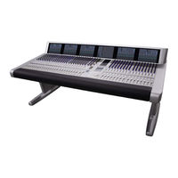
Euphonix System 5 Installation Manual (86 pages)
Brand:
Euphonix
| Category:
Music Mixer
| Size: 21 MB
Table of Contents
Installation Guide
1
Table of Contents
3
List of Figures
5
Chapter 1: System 5 Overview
9
Theory of Operation
9
Digital Signal Processing (DSP)
9
Control Surface
10
System Configuration
11
DAW Control
11
I/O
11
Monitoring
13
Snmp
13
Power
14
Sync
14
System Control Connections
15
Estimating System Requirements
16
Number of DF66 DSP Line Cards
16
DF66 Requirements
16
Number of CM408T Eight-Channel Sections
17
I/O Specification
17
Summary of Euphonix "Classic" Converters and Interfaces
17
Summary of Euphonix Modular I/O
17
Summary of System 5 Components
18
Chapter 2: Interconnecting System Components
19
Component Specifications
19
System 5 Components: Dimensions, Power Consumption, Heat Dissipation
19
Facility Power Quality Recommendations
21
Typical Room and Equipment Layout for System 5
23
Typical Console Layout
23
System 5 Console
23
Console Dimensions
24
Console Dimensions - Top
24
Console Dimensions - Side
24
S5MC Console Dimensions - Top
25
S5MC Console Dimensions - Side
25
Suggested Rack Elevations
27
Single and Redundant-Core Systems
27
Audio Hookup
28
Audio Hookup for Modular I/O
29
Synchronization Hookup
30
Recommended Sync Distribution Method
31
MADI Hookup
33
Control Hookup
35
Chapter 3: System 5 Components
36
DF66 Supercore
36
SP662, 6X6 Bridge, and Sync Cards
37
Sync Card
38
Bridge Card
38
SP662 DSP Line Card
38
MADI I/O DSP Line Card Cable
38
System 5 Console
39
Port BNC Bulkhead Panel
39
Typical Talkback Wiring
40
Switch Functions
40
SC263 System Computer (S5B Only)
41
SC263 Front and Rear Panels
41
SC264 System Computer
43
SC264 Front and Rear Panels
43
MC524 Monitor Interface
45
MC524 Front and Rear Panels
45
Input/Output Connections
46
Elco 38 Connector
46
In 1 Elco 38 Pinout
46
Elco 90 Connector
47
In 2 Elco 90 Pinout
47
Elco 90 Connector
48
Out 1 Elco 90 Pinout
48
Elco 90 Connector
49
Out 2 Elco 90 Pinout
49
DB-25 Connector
50
Out 3 DB-25 Pinout
50
ML530 MIC/Line Interface
51
ML530 Front and Rear Panels
51
ML530 in 1/In 2 Pinout: Elco 38 Socket
52
ML530 out 1/Out 2 Pinout: Elco 38 Socket
52
CO600 Changeover Switch
53
AM713 Analog to MADI Converter
54
Front Panel
54
AM713 Front Panel
54
Rear Panel
55
AM713 Rear Panel
55
MA703 MADI to Analog Converter
57
Front Panel
57
MA703 Front Panel
57
Rear Panel
58
MA703 Rear Panel
58
DM714 AES/EBU to MADI Converter
60
Front Panel
60
DM714 Front Panel
60
Rear Panel
61
DM714 Rear Panel
61
DM714 Parallel AES/EBU Digital Inputs: Female DB-25
62
MD704 MADI to AES/EBU Converter
63
Front Panel
63
MD704 Front Panel
63
Rear Panel
64
MD704 Rear Panel
64
DM704 Parallel AES/EBU Digital Outputs: Female DB-25
65
FC726 Format Converter
66
FC726 Front and Rear Panels
66
AES/EBU DB-25 Pinout
68
Common DD-50 Connector Pinout and Usage with Third-Party Devices
69
FC726 TDIF Cable Wiring Specification
70
FC726 SDIF Cable Wiring Specification
71
Modular I/O
72
Modular I/O Modules
73
More Modular I/O Modules
75
AD914 RJ-45 Pinout
76
Stagebox Configuration #1
77
Local-Side Interface Configuration #1
77
I/O Module Summary
78
Control Module Summary
78
Frame Summary
78
Tt002
79
Input and Output Connections
79
TT002 Card and Panels
79
TT002 P1 Connections and Pinouts
79
Connector Pinouts (DC-37 1 and 2)
80
Simplified TT002 GPO and GPI Circuits
81
FT730 Fibertran Fiberoptic Extender
82
FT730 Front Panel
82
FT730 Front Panel Status Leds
82
FT730 Rear Panel
83
Internal Sync Input Jumper
84
Rear Panel TCC, MADI, and Fiber Connectors
85
Advertisement
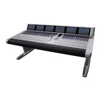
Euphonix System 5 Installation Manual (74 pages)
Brand:
Euphonix
| Category:
Music Mixer
| Size: 5 MB
Table of Contents
Revision History
2
Table of Contents
3
List of Figures
5
Chapter 1: System 5 Overview
9
Introduction to System 5
9
Digital Signal Processing (DSP)
9
The System 5 Console
9
Analog and Digital I/O
10
MIC Inputs
11
Monitoring
11
Power
11
Digital Sync
11
System Control Connections
12
Estimating System Requirements
14
Number of DF64 Digital Frames
14
Number of CM408 Eight-Channel Sections
14
DF64 Requirements
14
I/O Specification
15
Summary of System 5 Components
16
Chapter 2: Interconnecting System Components
17
Component Specifications
17
System 5 Components: Dimensions, Power Consumption, Heat Dissipation
17
Fuse Ratings for System 5 Components
19
Typical Room and Equipment Layout for System 5
20
Typical Console Layout
20
System 5 Console
20
Console Dimensions
21
Console Dimensions - Top
21
Console Dimensions - Side
21
Cm40X Module Dimensions
22
Suggested Rack Elevations
23
One- and Two-Frame Systems
23
Three-Frame System
24
Four-Frame System
24
Audio Hookup
25
Digital I/O
25
Analog I/O
25
Synchronization Hookup
26
Synchronization Hookup (Word Clock Shown, AES/EBU May be Used)
26
MADI Hookup
27
MADI Hookup: One DF64 Core, 10 or 11 DSP Cards, One SH612
27
MADI Hookup for Two DF64 Cores and One SH612 Studio Hub
28
MADI Hookup for Three DF64 Cores and Two SH612 Studio Hubs
29
MADI Hookup for Four DF64 Cores and Two SH612 Studio Hubs
30
Control Hookup
31
Chapter 3: System 5 Components
33
DF64 Digital Frame
33
DF64 Digital Frame Front and Rear Panels
33
FC631, MM641, and SP661 Cards
34
FC631 Frame Controller
35
MM641 MADI Interface Card
35
SP661 Signal Processor
35
System 5 Console
35
CM401 Expansion Port: DB-25 Female Pinout
36
Typical Talkback Wiring
36
Switch Functions
36
SC262 System Computer
37
SC262 Front and Rear Panels
37
Pc254D Digital Pilot Computer
38
Pc254D Front and Rear Panels
38
Pc254I Interface Computer
39
Pc254I Front and Rear Panels
39
MC524 Monitor Interface
40
MC524 Front and Rear Panels
40
Input/Output Connections
41
Elco 38 Connector
41
In 1 Elco 38 Pinout
41
Elco 90 Connector
42
In 2 Elco 90 Pinout
42
Elco 90 Connector
43
Out 1 Elco 90 Pinout
43
Elco 90 Connector
44
Out 2 Elco 90 Pinout
44
DB-25 Connector
45
Out 3 DB-25 Pinout
45
ML530 MIC/Line Interface
46
ML530 Front and Rear Panels
46
ML530 in 1/In 2 Pinout: Elco 38 Socket
47
ML530 out 1/Out 2 Pinout: Elco 38 Socket
47
SH612 Studio Hub
48
AM713 Analog to MADI Converter
49
Front Panel
49
AM713 Front Panel
49
Rear Panel
50
AM713 Rear Panel
50
MA703 MADI to Analog Converter
52
Front Panel
52
MA703 Front Panel
52
Rear Panel
53
MA703 Rear Panel
53
DM714 AES/EBU to MADI Converter
55
Front Panel
55
DM714 Front Panel
55
Rear Panel
56
DM714 Rear Panel
56
DM714 Parallel AES/EBU Digital Inputs: Female DB-25
57
MD704 MADI to AES/EBU Converter
58
Front Panel
58
MD704 Front Panel
58
Rear Panel
59
MD704 Rear Panel
59
DM704 Parallel AES/EBU Digital Outputs: Female DB-25
60
FC726 Format Converter
61
FC726 Front and Rear Panels
61
AES/EBU DB-25 Pinout
63
Common DD-50 Connector Pinout and Usage with Third-Party Devices
64
FC726 TDIF Cable Wiring Specification
65
FC726 Pro Tools Cable Wiring Specification
66
FC726 SDIF Cable Wiring Specification
67
Gp132
68
Front Panel Functions
68
25-Pin D-Sub Connectors RT1-RT4
68
GP132 Front and Rear Panels
68
MIDI Connections
69
Input and Output Connections
69
Connector Pinouts (DB-25 RT1-RT4)
69
GP132 Input and Output Connections
69
GP132 Outputs
69
GP132 Inputs
70
Tt007
71
Setup
71
Capabilities
71
Using the TT007
72
TT007 Front and Rear Panels
72
Euphonix System 5 Installation Manual (77 pages)
Brand:
Euphonix
| Category:
Music Mixer
| Size: 8 MB
Table of Contents
Table of Contents
3
List of Figures
5
Chapter 1: System 5 Overview
9
Introduction to System 5
9
Digital Signal Processing (DSP)
9
The System 5 Console
9
Analog and Digital I/O
10
MIC Inputs
11
Monitoring
11
Power
11
Digital Sync
11
System Control Connections
12
Estimating System Requirements
14
Number of DF66 DSP Line Cards
14
Number of CM408T Eight-Channel Sections
14
DF66 Requirements
14
I/O Specification
15
Summary of System 5 Components
16
Chapter 2: Interconnecting System Components
17
Component Specifications
17
System 5 Components: Dimensions, Power Consumption, Heat Dissipation
17
Fuse Ratings for System 5 Components
19
Typical Room and Equipment Layout for System 5
20
Typical Console Layout
20
System 5 Console
20
Console Dimensions
21
Console Dimensions - Top
21
Console Dimensions - Side
21
S5MC Console Dimensions - Top
22
S5MC Console Dimensions - Side
22
Suggested Rack Elevations
24
Single and Redundant-Core Systems
24
Audio Hookup
25
Synchronization Hookup
26
Recommended Sync Distribution Method
27
MADI Hookup
29
Control Hookup
32
Chapter 3: System 5 Components
33
DF66 Supercore
33
SP662, 6X6 Bridge, and Sync Cards
34
Sync Card
35
DSP Line Card
35
SP661 Signal Processor
35
MADI I/O DSP Line Card Cable
35
System 5 Console
36
Typical Talkback Wiring
37
Switch Functions
37
SC263 System Computer
38
SC263 Front and Rear Panels
38
Pc254I Interface Computer
39
Pc254I Front and Rear Panels
39
MC524 Monitor Interface
40
MC524 Front and Rear Panels
40
Input/Output Connections
41
Elco 38 Connector
41
In 1 Elco 38 Pinout
41
Elco 90 Connector
42
In 2 Elco 90 Pinout
42
Elco 90 Connector
43
Out 1 Elco 90 Pinout
43
Elco 90 Connector
44
Out 2 Elco 90 Pinout
44
Out 3 DB-25 Pinout
45
DB-25 Connector
45
ML530 MIC/Line Interface
46
ML530 Front and Rear Panels
46
ML530 in 1/In 2 Pinout: Elco 38 Socket
47
ML530 out 1/Out 2 Pinout: Elco 38 Socket
47
Failover Switch
48
AM713 Analog to MADI Converter
49
Front Panel
49
AM713 Front Panel
49
Rear Panel
50
AM713 Rear Panel
50
MA703 MADI to Analog Converter
52
Front Panel
52
MA703 Front Panel
52
Rear Panel
53
MA703 Rear Panel
53
DM714 AES/EBU to MADI Converter
55
Front Panel
55
DM714 Front Panel
55
Rear Panel
56
DM714 Rear Panel
56
DM714 Parallel AES/EBU Digital Inputs: Female DB-25
57
MD704 MADI to AES/EBU Converter
58
Front Panel
58
MD704 Front Panel
58
Rear Panel
59
MD704 Rear Panel
59
DM704 Parallel AES/EBU Digital Outputs: Female DB-25
60
FC726 Format Converter
61
FC726 Front and Rear Panels
61
AES/EBU DB-25 Pinout
63
Common DD-50 Connector Pinout and Usage with Third-Party Devices
64
FC726 TDIF Cable Wiring Specification
65
FC726 SDIF Cable Wiring Specification
67
Gp132
68
Input and Output Connections
68
GP132 Front and Rear Panels
68
GP132 Input and Output Connections
68
Connector Pinouts (DB-25 RT1-RT4)
69
GP132 Outputs
69
GP132 Inputs
69
Tt007
70
TT007 Front and Rear Panels
70
Euphonix System 5 Manual (50 pages)
Control Surface/Frame
Brand:
Euphonix
| Category:
Music Mixer
| Size: 3 MB
Table of Contents
Table of Contents
2
Box Inventory
4
Safety and Precautions
4
Power on Sequence
5
Ce/Tuv/Ul/Csa
5
Component Overview
6
Functional Description
6
Frame Section
7
Physical Specifications
7
Exploded View
7
Side Panel View
8
Dimensions and Weight
9
User Reference - Frame
10
Assembling the S5 Frame
10
System 5 Ethernet/Power Cable Configuration
18
System 5 Ethernet Cable Harness
19
Control Modules Section
21
Physical Specifications
21
Top View - Control Modules
21
Filler Modules
22
Dimensions and Weight
23
Technical Specifications
23
Environmental Requirements
23
Power Requirements
23
Power Consumption
23
Control Module Expansion Port
24
General Description
24
Physical Pinout
24
DB25 Electrical Specification
26
Typical Usage
26
Alternate Usage #1
27
Alternate Usage #2
28
User Reference - Control Modules
29
Control Module Setup
29
Overview of Ethernet IP Address Allocation
29
Self Test Procedure for CM401, CM402 and CM408
30
Initiating Self Test
31
Self Test Operations
32
Top Level Test Keys
33
LED Test
34
All Switch Leds Toggle
35
Color Toggle
35
All Switch and Indicator Leds Toggle
35
Vegas Mode
35
Switch Test
36
Intelligent Display Test
37
Knob Test
38
Knob Value Display
39
Halo Test
39
Knob Meter Display
39
Knob Switch Test
39
Expansion Port Switch Test
39
Fader Test
40
Fader Test (Continued)
41
All Fader up
42
All Fader down
42
Fader Cycle Test with Speed Control
42
Fader Echo Test
42
Touch Sense Test
42
Backstop PFL Switch Test
42
Fader Write Value Display
42
Fader Read Value Display
42
TFT Backlight Brightness Test
42
CPU Test
43
RAM Test
43
ROM Test
43
PC104 RAM Test
44
Euphonix System 5 Brochure (36 pages)
Digital Audio Mixing System
Brand:
Euphonix
| Category:
Music Mixer
| Size: 4 MB
Table of Contents
Table of Contents
2
System 5
4
System 5 Key Features
4
Innovative Solutions
4
Audio Interfaces
5
System Components
5
The Control Modules
6
Typical Equipment Rack
6
System 5 Control Surface - 6 Module Frame
7
Channels
8
Strips
9
Inputs
11
Channel Process Order
12
EQ & Filters
12
Dynamics
13
Bus Routing and aux Sends
14
Pan Controls
15
Meters
16
Master Facilities
17
Master Fader
19
Bus Masters
19
Main Panel
20
Master Meters
20
Monitor Source Selection
21
External Inputs
21
Machine Control
23
Solo-In-Place
23
Multi-Operator Systems
23
Film Post-Production Monitoring Panel
24
System 5 Multi-Operator Configuration
25
Snapshot Recall
26
Total Automation
26
Fader and Knob Automation Modes
27
Conforming
27
CM403 Joysticks
27
Patching - Patchnet
28
File Management
29
DF66 DSP Supercore with MADI I/O & Router
30
SC263 Studio Computer
31
AM713 Analog to MADI Converter
32
MA703 MADI to Analog Converter
32
Interfaces to the Analog & Digital Worlds
32
Get Connected
34
Eucon Hybrid Option
34
Digital Factory, Normandy, France
36
Euphonix System 5 Setup Manual (29 pages)
Post and Film
Brand:
Euphonix
| Category:
Music Mixer
| Size: 0 MB
Table of Contents
Table of Contents
3
CM403 Installation
5
CM403 Module
5
External Record Control
6
Film Panel Installation
7
Joystick Panel Installation
9
Blank Panel
10
Record Control Setup
11
Solo Linking
12
Physical Connection between Systems
12
Network Settings
13
Setting up Moconfig
28
Bus Cascade Inputs
28
Block Diagram
29
Euphonix System 5 Application Note (2 pages)
Metering: Peak vs. Average, eMix software
Brand:
Euphonix
| Category:
Software
| Size: 0 MB
Advertisement
Related Products
Euphonix System 5B
Euphonix System 5 Control Surface/Frame
Euphonix 5-MC
Euphonix System 5 PC 254H
Euphonix EuCon
Euphonix Max Air
Euphonix Max Air Control surface
Euphonix MC Mix
Euphonix MixView CS2000
Euphonix MixView CS3000
Euphonix Categories
Music Mixer
Recording Equipment
Music Equipment
Media Converter
Software
More Euphonix Manuals
Login
Sign In
OR
Sign in with Facebook
Sign in with Google
Upload manual
Upload from disk
Upload from URL