Euphonix System 5 Installation Manual
Hide thumbs
Also See for System 5:
- Manual (228 pages) ,
- Operation manual (228 pages) ,
- Installation manual (77 pages)
Table of Contents
Advertisement
Quick Links
Advertisement
Table of Contents

Related Manuals for Euphonix System 5


Summary of Contents for Euphonix System 5
-
Page 1: Installation Guide
Euphonix System Installation Guide Document Revision: 3.0 Part Number: 840-07591-05 Release Date: April, 2008 Euphonix, Inc. 220 Portage Ave. Palo Alto, California 94306 Phone: 650-855-0400 Fax: 650 -855-0410 Web: http://www.euphonix.com e-mail: info@euphonix.com... - Page 2 System 5, S-5, PatchNet, eMix, EuCon, R-1, Audio Deck, Studio Hub are trademarks of Euphonix, Inc. ©2008 Euphonix, Inc. All rights reserved worldwide. No part of this publication may be reproduced, transmitted, transcribed, stored in a retrieval system, or translated into any language in any form by any means without written permission of Euphonix, Inc.
-
Page 3: Table Of Contents
I/O Specification ..................17 Chapter 2: Interconnecting System Components ..........19 Component Specifications ..................19 Facility Power Quality Recommendations ............21 Typical Room and Equipment Layout for System 5 ..........23 Typical Console Layout ..................23 Console Dimensions ...................24 Suggested Rack Elevations .................27 Audio Hookup.....................28 Audio Hookup for Modular I/O ................29 Synchronization Hookup ..................30... - Page 4 Euphonix System 5 Installation Guide Chapter 3: System 5 Components ................36 DF66 SuperCore....................36 Sync Card....................38 Bridge Card .................... 38 SP662 DSP Line Card................38 System 5 Console....................39 SC263 System Computer (S5B only) ..............41 SC264 System Computer ..................43 MC524 Monitor Interface ...................45...
-
Page 5: List Of Figures
Euphonix System 5 Installation Guide List of Figures Typical Room and Equipment Layout for System 5 ............23 System 5 Console ......................23 Console Dimensions - Top ....................24 Console Dimensions - Side ....................24 S5MC Console Dimensions - Top..................25 Console Dimensions - Side.................. - Page 6 Euphonix System 5 Installation Guide 3-16 ML530 In 1/In 2 Pinout: Elco 38 Socket ................52 3-17 ML530 Out 1/Out 2 Pinout: Elco 38 Socket ..............52 3-18 CO600 Changeover Switch ....................53 3-19 AM713 Front Panel ......................54 3-20 AM713 Rear Panel ......................55 3-21 MA703 Front Panel ......................57...
- Page 7 Summary of Euphonix “Classic” Converters and Interfaces .......... 17 Summary of Euphonix Modular I/O................17 Summary of System 5 Components ................18 System 5 Components: Dimensions, Power Consumption, Heat Dissipation ....19 Switch Functions ......................4 0 In 1 Elco 38 Pinout ......................44 In 2 Elco 90 Pinout ......................
- Page 8 Euphonix System 5 Installation Guide This page is intentionally blank. viii...
-
Page 9: Chapter 1: System 5 Overview
I/O system, an integrated MADI router, a serial machine control interface, and GPIO. These options allow the System 5 to be configured for virtually any audio mixing applica- tions, including large-scale film production, on-air broadcast, post-production, and music. -
Page 10: Control Surface
Below are important concepts regarding control surface configuration: Sources A System 5 fader can control one source at a time. Sources may be formatted to be mono, stereo, or any format up to 7.1. Each source will require one or more logical channels. -
Page 11: System Configuration
DAWs, including Nuendo, ProTools, Logic Pro, and Pyramix. The SC264 connects with DAWs via a 1000Base-T network switch. Euphonix offers a variety of I/O solutions -- all employing MADI audio for connecting to the DF66/CO600. These include Euphonix “Classic” stand-alone 2RU MADI converters as well as a flexible Modular I/O system. - Page 12 The ML530 Mic-Line Interface contains 24 remote-controlled mic preamps. Audio outputs are fed to a dedicated AM713 Analog-to-MADI Converter for MADI con- nection to the DF66/CO600. The ML530 is controlled via the Euphonix TCC serial protocol (proprietary) by the System Computer. Up to seven ML530s may be de- ployed in a system.
-
Page 13: Monitoring
Monitoring System 5 monitoring is handled by the MC524 Monitor-Comms Interface. This unit provides Main (7.1), Alt 1 (5.1), and Alt 2 (stereo) control room speaker outputs; SLS (7.1), and Cues 1-3 (each stereo) studio speaker outputs; 2 talkback mic preamps and 4 listen mic preamps. -
Page 14: Power
System 5 Overview Power Most of the System 5 console components have dual power entry connectors for redun- dant power supplies. Euphonix recommends deriving power from two different sources to maximize the failsafe capabilities. The best case is to connect one power supply to a UPS (Uninterruptible Power Supply) and the other to a clean technical power source. -
Page 15: System Control Connections
Euphonix System 5 Installation Guide System 5 Overview System Control Connections Ethernet All primary system components are connected via RJ45 ethernet through a 100Base-T ethernet switch. These devices include: • System Computer (SC263 or SC264) • CM401T Master Fader Module (console center section) •... -
Page 16: Estimating System Requirements
This section helps estimate the system requirements for a particular installation. Contact a Euphonix representative for an exact specification. Use the following categor ies to deter- mine the System 5 components necessary for your studio. Most of the details considered here are relevant to any digital mixing system. -
Page 17: Number Of Cm408T Eight-Channel Sections
In the case of modular I/O, only mic, analog, AES, and embedder/de-embedder modules are shown. Refer to the Euphonix Modular I/O Configuration Guide for more details on sync, MADI I/O, and remote control modules as well as general configuration require- ments. -
Page 18: Summary Of System 5 Components
Euphonix System 5 Installation Guide System 5 Overview The following chart summarizes this section: Table 1-4 Summary of System 5 Components Component Function Number Notes CM401T Ethernet devices. CM40 1T includes Master Module These two modules make up the center section... -
Page 19: Chapter 2: Interconnecting System Components
Chapter 2: Interconnecting System Components This chapter summarizes technical information for System 5’s components, including size, weight, power consumption, cooling, and fuse requirements and shows their interconnections. To plan an installation, examine Figure 2-1 to learn about suggested equipment locations. - Page 20 Euphonix System 5 Installation Guide Interconnecting System Components 17”/432 mm 3.5” 17 lb MC524 18.5” 70 W 240 BTU/hr (19”/483 mm 89 mm 7.7 kg 470 mm Monitor Interface faceplate) 3.5” 17”/432 mm ML530 18.5” 17 lb 345 BTU/hr 100 W 89 mm (19”/483 mm...
-
Page 21: Facility Power Quality Recommendations
4 microseconds and 1 cycle (17mS at 60Hz) and exceed 50% or greater than the nominal voltage level. Euphonix's products have been tested and found to comply with the performance limits of EN55103:2, E-4 Environment. Should the product be operated in a degraded power environment, care should be taken to insure that the EN55102 electronic limits are not exceeded. - Page 22 Short-duration undervoltages are called "voltage sags" or "voltage dips". A voltage sag below 90% of the equipment rating exceeds the minimum allowable standard. Euphonix's products have been tested and found to comply with the performance limits of EN55103:2, E-4 Environment. Should the product be operated in a degraded power environment, care should be taken to insure that the EN55102 Voltage Dips and Interrupt limits are not exceeded.
-
Page 23: Typical Room And Equipment Layout For System 5
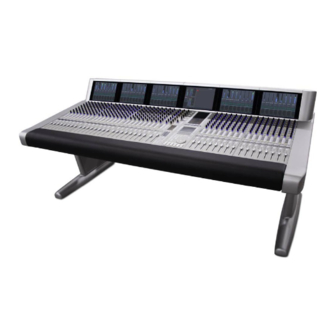
Mic-Line IF & Patch Mic-Line ADC Analog IF & Patch AES/EBU IF & Patch Monitor IF & Patch Monitor DAC HD/SD Embedder/ De-embedder (optional) Figure 2-1 Typical Room and Equipment Layout for System 5 Typical Console Layout Figure 2-2 System 5 Console... -
Page 24: Console Dimensions
Euphonix System 5 Installation Guide Interconnecting System Components Console Dimensions 72.0 41.0 Figure 2-3 Console Dimensions - Top 30.5 39.5 29.5 24.2 Figure 2-4 Console Dimensions - Side... -
Page 25: S5Mc Console Dimensions - Top
Euphonix System 5 Installation Guide Interconnecting System Components Figure 2-5 S5MC Console Dimensions - Top Figure 2-6 S5MC Console Dimensions - Side... - Page 26 Euphonix System 5 Installation Guide Interconnecting System Components 1.75 2.43 120.0 9.12 9.69 24.63 60.0 100.0 1.61 3.08 2.49 29.52 11.96 33.65 Figure 2-7 CM40x Module Dimensions...
-
Page 27: Suggested Rack Elevations
Euphonix System 5 Installation Guide Interconnecting System Components Suggested Rack Elevations Leave Open EuCon Switch System PC Leave Open Eucon Switch DF66 SuperCore 1 System PC CO600 Changeover Switch DF66 SuperCore DF66 SuperCore 1A Leave Open Leave Open Figure 2-8 Single and Redundant-core Systems... -
Page 28: Audio Hookup
Euphonix System 5 Installation Guide Interconnecting System Components Audio Hookup Microphone ML530 OUTPUTS INPUTS AM713 1-12 24 Analog 48 Analog 13-24 Studio Mic Lines ML530 OUTPUTS INPUTS AM713 24 Analog 1-12 1-48 13-24 Mic Line Interface Analog to MADI Digital I/O... -
Page 29: Audio Hookup For Modular I/O
Euphonix System 5 Installation Guide Interconnecting System Components Audio Hookup for Modular I/O Microphone 4~56 Analog Studio Mic Lines 4~56 Analog to MADI Mic Line Interface Digital I/O AES/EBU PSU #1 PSU #1 PSU #2 PSU #2 4~64 channels (2~32 AES/EBU pairs) -
Page 30: Synchronization Hookup
Euphonix System 5 Installation Guide Interconnecting System Components Synchronization Hookup PSU #1 PSU #2 Modular I/O OUTPUTS INPUTS ML530 1-12 W/C In Maximum Cable Distances: 13-24 Word: 165 ft (50 m) AM713 Alternate Sync Distances: OUTPUTS INPUTS ML530 1-12 W/C In... -
Page 31: Recommended Sync Distribution Method
• These sync generators may be set to internal or gen-locked to a video reference. • Use a Euphonix recommended distribution amp (see next page) to feed all sys- tem components and additional studio devices directly. • Cable runs from the master clock to the distribution amps should be equal in length (AES11-1997, 5.4) - Page 32 Euphonix System 5 Installation Guide Interconnecting System Components System Components That Require Digital Sync • DF66 DSP Cores • AM713 Analog to MADI Converters • MA703 MADI to Analog Converters • DM714 AES to MADI Converters • MD704 MADI to AES Converters •...
-
Page 33: Madi Hookup
Euphonix System 5 Installation Guide Interconnecting System Components MADI Hookup DF66 with 1 DSP Maximum MADI Line Card Cable Distance: 165 ft (50m) Source Destination DF66 MADI Inputs MADI Outputs MADI Inputs MADI Outputs MA703 MADI to Analog Converter for MC524... - Page 34 Although maximum recommended distan- ces over copper can be exceeded with the use of high performance compo- nents (including cables), it is not Euphonix's intention to endorse any particular brand or method of achieving the end result.
-
Page 35: Control Hookup
Euphonix System 5 Installation Guide Interconnecting System Components Control Hookup Up to six additional Mic/Line Interfaces Sony 9-pin Maximum Distances OUTPUTS INPUTS ML530 1-12 Ethernet: 91.4 m (300ft) 13-24 TCC Control: 228.6 m (750ft) System Computer MIDI: 6m (20ft) Mic/Line Interface... -
Page 36: Chapter 3: System 5 Components
Euphonix System 5 Installation Guide System 5 Components Chapter 3: System 5 Components This chapter discusses the System 5 components and all connectors necessary for operation. Pinouts for user-wired connections are shown for each component, along with the cables and connectors provided by Euphonix. -
Page 37: Sp662, 6X6 Bridge, And Sync Cards
Euphonix System 5 Installation Guide System 5 Components Figure 3-2 SP662, 6x6 Bridge, and Sync Cards... -
Page 38: Sync Card
Euphonix System 5 Installation Guide System 5 Components Sync Card AES Sync In (BNC): The DF66 SuperCore clocks to the signal at this port when the sync source is set to AES Sync. Connect this port to a digital sync reference. -
Page 39: System 5 Console
RJ-45 ethernet port and an RS232 serial port. System 5 Console The System 5 Console consists of several modular components: the CM401T and CM402T(console center section), the CM408T (contains eight physical faders and con- trols), the CM403 (contains the joystick panner panel and film monitor panel), and the CM409HTP Track Panner Module. -
Page 40: Typical Talkback Wiring
Euphonix System 5 Installation Guide System 5 Components Pin # Signal LED 1 output (active low) Switch 1 input (active high) LED 3 output (active low) Switch 3 input (active high) LED 5 output (active low) Switch 5 input (active high) -
Page 41: Sc263 System Computer (S5B Only)
Euphonix System 5 Installation Guide System 5 Components SC263 System Computer (S5B only) Figure 3-7 SC263 Front and Rear Panels VGA Connector (DA-15): Main video monitor connection. - Page 42 Euphonix System 5 Installation Guide System 5 Components Power Connectors (IEC): Accepts two standard IEC power cords (provided). Two autorang- i ng switching supplies accept voltages between 100–240 VAC, 50–60 Hz. TCC Main Port (DC-62): Connect TCC breakout cable (provided) to this port. This cable breaks out to four DA-15 connectors that provide control hookup for the MC524 Monitor Interface and three ML530 Mic/Line Interfaces.
-
Page 43: Sc264 System Computer
Euphonix System 5 Installation Guide System 5 Components SC264 System Computer Figure 3-8 SC264 Front and Rear Panels VGA Connector (DA-15): Main video monitor connection. - Page 44 More than one integrated DAW can share the same display by using the Ontrack ADU- 200 relay device (available from Euphonix) to control a KVM (keyboard/video mouse) switch with an RJ-45 port, such as the Gefen eX-Tend-It series. To implement this func- tionality: 1.
-
Page 45: Mc524 Monitor Interface
Listen pre, two Talk Back pre and two Solo channels . Output cable fans out to eight male XLRs. Control (DA15): Input for digital control signal from System Computer (Euphonix TCC bi- directional serial protocol). Al l patching, switching, and gain controls are communicated via this connection. -
Page 46: Input/Output Connections
Euphonix System 5 Installation Guide System 5 Components Input/Output Connections Table 3-2 In 1 Elco 38 Pinout Crk # Designator 24 X 32 High Talk Talk Listen Listen Listen Listen Figure 3-10 Elco 38 Connector, rear view... -
Page 47: Elco 90 Connector
Euphonix System 5 Installation Guide System 5 Components Table 3-3 In 2 Elco 90 Pinout Crk # Designator 24 X 32 High Cntrl Rm (L) Cntrl Rm (C) Cntrl Rm (R) Cntrl Rm (Sl) Cntrl Rm (Sr) Cntrl Rm (B) -
Page 48: Elco 90 Connector
Euphonix System 5 Installation Guide System 5 Components Table 3-4 Out 1 Elco 90 Pinout Crk # Designator 24 X 32 High BO11 Mon A (L) BO12 Mon A (C) BO17 Mon A (R) BO18 Mon A (Sl) BO19 Mon A (Sr) -
Page 49: Elco 90 Connector
Euphonix System 5 Installation Guide System 5 Components Table 3-5 Out 2 Elco 90 Pinout Crk # Designator 24 X 32 High BO31 Solo L BO32 Solo R Talk 1 Talk 2 Listen 1 Listen 2 Listen 3 Listen 4... -
Page 50: Db-25 Connector
Euphonix System 5 Installation Guide System 5 Components Table 3-6 Out 3 DB-25 Pinout Crk # Designator 24 X 32 High Solo L Solo R 10 9 8 Figure 3-14 DB-25 Connector... -
Page 51: Ml530 Mic/Line Interface
Euphonix System 5 Installation Guide System 5 Components ML530 Mic/Line Interface MIC LINE INTERFACE OUTPUTS INPUTS ML530 1-12 CONTROL 13-24 Figure 3-15 ML530 Front and Rear Panels Inputs (two 38-pin ELCO sockets): A total of 24 microphone inputs are received on two 38-pin ELCO connectors (connectors and pins provided). -
Page 52: Ml530 In 1/In 2 Pinout: Elco 38 Socket
Euphonix System 5 Installation Guide System 5 Components Signal Wiring Instruction & Description Mic In 1 / Mic In 13 From studio Mic 1 / 13 Mic In 2 / Mic In 14 From studio Mic 2 / 14 Mic In 3 / Mic In 15... -
Page 53: Co600 Changeover Switch
Euphonix System 5 Installation Guide System 5 Components CO600 Changeover Switch Figure 3-18 CO600 Changeover Switch Network Port (RJ45): Connect to the Eucon Network Switch via the RJ-45 cable provided. MADI In / Out Ports (96 Combo D): Digital audio in and outs. See the MADI for details on these connections. -
Page 54: Am713 Analog To Madi Converter
Euphonix System 5 Installation Guide System 5 Components AM713 Analog to MADI Converter Front Panel Figure 3-19 AM713 Front Panel Signal Strength LEDs: Each of the 28 channels has a four-segment LED that represents the following signal levels: -42 dB, -18 dB, -6 dB (green), -0.05 dB (red). -
Page 55: Rear Panel
Euphonix System 5 Installation Guide System 5 Components Rear Panel AM713 DIGITAL ANALOG INPUTS INPUTS MADI Figure 3-20 AM713 Rear Panel Input Voltage Selector: This red switch allows the unit to operate in either 100/110/115 VAC or 220/230/240 VAC environments. A fuse must also be changed for 220/230/240 VAC operation. - Page 56 Euphonix System 5 Installation Guide System 5 Components MADI Out (BNC): Outputs the digital audio signal. • 1–24: Analog inputs • 25–26: Aux analog inputs • 27–28: Aux digital inputs NOTE: 28 channels are always transmitted; dual channels are not used.
-
Page 57: Ma703 Madi To Analog Converter
Euphonix System 5 Installation Guide System 5 Components MA703 MADI to Analog Converter Front Panel Figure 3-21 MA703 Front Panel Signal Strength LEDs: Each of the 28 channels has a four-segment LED that represents the following signal levels: -42 dB, -18 dB, -6 dB (green), -0.05 dB (red). -
Page 58: Rear Panel
Euphonix System 5 Installation Guide System 5 Components Rear Panel MA703 DIGITAL ANALOG OUTPUTS OUTPUTS MADI Figure 3-22 MA703 Rear Panel Input Voltage Selector: This red switch allows the unit to operate in either 100/110/ 115 VAC or 220/230/240 VAC environments. A fuse must also be changed for 220/ 230/240 VAC operation. - Page 59 Euphonix System 5 Installation Guide System 5 Components MADI In (BNC): Digital audio signal input. • 1–24: analog outputs • 25–26: aux analog outputs • 27–28: aux digital outputs.
-
Page 60: Dm714 Aes/Ebu To Madi Converter
Euphonix System 5 Installation Guide System 5 Components DM714 AES/EBU to MADI Converter Front Panel Figure 3-23 DM714 Front Panel Signal Strength LEDs: Each of the 28 channels has a four-segment LED that represents the following signal levels: -42 dB, -18 dB, -6 dB (green), -.05 dB (red). -
Page 61: Rear Panel
Euphonix System 5 Installation Guide System 5 Components Manual Selection Buttons: The button below each Sample Rate LED row manually selects the Sample Rate Source. The DM714 also allows manual selection of the Sample Rate. Power Switch: On/Off switch. Rear Panel... -
Page 62: Dm714 Parallel Aes/Ebu Digital Inputs: Female Db-25
Euphonix System 5 Installation Guide System 5 Components Word Out (BNC): Outputs a Word clock signal synchronized to the Sample Rate Source. In the presence of an external Word clock input, this connector provides a regenerated ver- sion of that input signal. Without an external sample rate source, this connector outputs the internally generated clock signal. -
Page 63: Md704 Madi To Aes/Ebu Converter
Euphonix System 5 Installation Guide System 5 Components MD704 MADI to AES/EBU Converter Front Panel MADI TO DIGITAL WORD 44.1 MADI AUTO CUSTOM TRIM Figure 3-26 MD704 Front Panel Signal Strength LEDs: Each of the 28 channels has a four-segment LED that represents the following signal levels: -42 dB, -18 dB, -6 dB (green), -.05 dB (red). -
Page 64: Rear Panel
Euphonix System 5 Installation Guide System 5 Components Rear Panel BIT-DEPTH REDUCTION PARALLEL AES/EBU INPUTS 7 / 8 5 / 6 3 / 4 MD704 7 / 8 5 / 6 3 / 4 DIGITAL AES/EBU OUTPUTS OUTPUTS MADI D1/D2... -
Page 65: Dm704 Parallel Aes/Ebu Digital Outputs: Female Db-25
Euphonix System 5 Installation Guide System 5 Components MADI In (BNC): Digital audio signal input. • 1–24: main digital outputs • 25–26: aux analog outputs • 27–28: aux digital outputs Bit-Depth Reduction: Sets the resolution to 16, 20, or 24 bits for the main AES/EBU channels. -
Page 66: Fc726 Format Converter
MADI A In 1 / MADI A Out 1 (two BNC): The MADI A In/Out Ports interface with non-Euphonix MADI devices. At 48 kH z, MADI A provides 56 channels of 24-bit audio; at 96 kHz, 28 channels of 24-bit audio channels (cable not provided). - Page 67 Euphonix System 5 Installation Guide System 5 Components SDIF-2 or Slave Clock In (BNC): This connector can receive either an SDIF or Slave Clock Sync signal (the FC726 automatically detects the signal type). An SDIF device must send a Word Sync signal to this connector to interface properly. Slave Clock is a sync signal (commonly implemented in Pro Tools systems and referred to as a super-clock) that runs at 256 times the sample rate.
-
Page 68: Aes/Ebu Db-25 Pinout
Euphonix System 5 Installation Guide System 5 Components Table 3-7 AES/EBU DB-25 Pinout Description Pin 1 Pin 2 Channel 1 / 2 In (COLD) Pin 3 Channel 3 / 4 In (GND) Pin 4 Channel 3 / 4 In (HOT) -
Page 69: Common Dd-50 Connector Pinout And Usage With Third-Party Devices
Euphonix System 5 Installation Guide System 5 Components Table 3-8 Common DD-50 Connector Pinout and Usage With Third-party Devices Common Connector (DD50 Female) SDIF usage TDIF usage ProDigi usage ADAT usage Pin # 1 In 1+ In 1+ In 1+... -
Page 70: Fc726 Tdif Cable Wiring Specification
Euphonix System 5 Installation Guide System 5 Components Table 3-9 FC726 TDIF Cable Wiring Specification Connector Pin Connection Description 1 NC 2 J2-1 In 1/2 3 NC 4 J2-2 In 3/4 5 NC 6 J2-3 In 5/6 7 NC 8 J2-4... -
Page 71: Fc726 Sdif Cable Wiring Specification
Euphonix System 5 Installation Guide System 5 Components Table 3-10 FC726 SDIF Cable Wiring Specification Connector Pin Connection Description In 1+ 1 J4-2 In 1- 2 J4-1 In 3+ 3 J4-6 In 3- 4 J4-5 In 5+ 5 J4-10 In 5-... -
Page 72: Modular I/O
I/O Cards Figure 3-30 IO93 Modular I/O Frame Front and Rear Panels The Euphonix Modular I/O system allows I/O configuration flexibility. Several frame types can be fitted with a variety of I/O and control modules. All audio sig- nals are converted to/from MADI for interfacing to the console. Depending on the configuration, a maximum signal density of 64 inputs and 64 outputs on a single MADI I/O is possible. -
Page 73: Modular I/O Modules
Euphonix System 5 Installation Guide System 5 Components • Any frame fitted with modules requiring remote control must be fitted with an FC972 Remote module for TCP/IP interfacing to the console network. • A frame must have a master sync module. This may be a dedicated sync mo- dule or a MADI I/O module set to “sync-to-MADI”. - Page 74 Euphonix System 5 Installation Guide System 5 Components is accomplished through a crosspoint matrix with preset capability. The matrix is configured via a web browser interface. In Master mode, the MM934 can provide sync to the frame from the MADI input. In this mode, it must be installed in one of the four “reserved” slots on the rear-plane.
-
Page 75: More Modular I/O Modules
Euphonix System 5 Installation Guide System 5 Components Figure 3-32 More Modular I/O modules DD908 4ch AES In/Out (two female XLR, two male XLR): The DD908 is a 4ch AES/EBU input/output interface. -
Page 76: Ad914 Rj-45 Pinout
Live Screen Screen Return Figure 3-33 AD914 RJ-45 Pinout Refer to the Euphonix Modular I/O Configuration Guide for more details and configuration possibilities. Frames Power Connectors (IEC): The frame comes standard with an auto-sensing (100~ 240vAC, 50/60Hz), dual redundant PSU. -
Page 77: Stagebox Configuration #1
Euphonix System 5 Installation Guide System 5 Components Figure 3-34 Stagebox configuration #1 IO95 Modular I/O Frame: The IO95 frame is a double-sided 3RU frame identical to the IO93 frame, except for an audio buss modification. This modification con- sists of separating audio busses on the rear-plane to provide four “positions” to be used as local-side interfaces for redundant MADI-over-fiber stageboxes. -
Page 78: I/O Module Summary
Euphonix System 5 Installation Guide System 5 Components Table 3-11 I/O Module Summary Table 3-12 Control Module Summary Table 3-13 Frame Summary... -
Page 79: Tt002
Euphonix System 5 Installation Guide System 5 Components TT002 Figure 3-36 TT002 card and panels The TT002 is a single-port RS422 (Sony 9-pin) machine controller that is installed in the System Computer. It also supports Midi Machine Control (MMC), and can read and generate timecode over MIDI, RS422, and LTC. -
Page 80: Connector Pinouts (Dc-37 1 And 2)
Euphonix System 5 Installation Guide System 5 Components Connector Pinouts (DC-37 GP1–GP2) Table 3-13 GP1 Inputs and Outputs Description Description Description Description GPI 1 GPI 11 GPO 2 GPO 12 GPI 2 GPO 13 GPI 12 GPO 3 GPI 3... -
Page 81: Simplified Tt002 Gpo And Gpi Circuits
Euphonix System 5 Installation Guide System 5 Components Simplified Diagram of TT002 GPIO Circuit Figure 3-38 Simplified TT002 GPO and GPI circuits The voltage input range for the TT002 GPI is 0 to 2.5 volts DC for a valid logic “low”, and 2.5 volts to 5 volts DC for a valid logic “high”. -
Page 82: Ft730 Fibertran Fiberoptic Extender
Line preamplifier or MC524 Monitor Controller to be placed up to 1 km away from the processing core of a Euphonix digital console. The FT730 is always used in pairs with one local unit at the control end and one remote unit at the far end connected by up to 1 km of fiberoptic cable. -
Page 83: Ft730 Rear Panel
Euphonix System 5 Installation Guide System 5 Components • Solid - indicates power supply is functioning normally. • Flashing - indicates the remote power supply has failed. • Off - indicates the local power supply has failed. Sync Remote - The unit is locked to sync coming from the local unit over the fiber link. -
Page 84: Internal Sync Input Jumper
Euphonix System 5 Installation Guide System 5 Components Figure 3-42 Rear Panel Sync Connectors AES/SYNC IN (female XLR or BNC), WORD IN (BNC): Connect this port to a digital sync reference (local unit only). Selection for XLR or BNC input is done using two internal jumpers shown in Figure 3-39 Internal Sync Input Jumper. -
Page 85: Rear Panel Tcc, Madi, And Fiber Connectors
System 5 Installation Guide System 5 Components Figure 3-44 Rear Panel TCC, MADI, and Fiber Connectors TCC IN/Out (DB15): Connect TCC IN to TCC control port at local unit. Connect TCC OUT to TCC control port at remote unit. - Page 86 Euphonix System 5 Installation Guide System 5 Components NOTE: Do NOT connect your DAWs to the System 5 console network switch. For fixed IP configurations please see your netowrk administrator. KVM Connection (Optional) The Hybrid Pilot can use the Ontrack ADU-200 relay device (available from Euphonix) to control a KVM (keyboard/video/mouse) switch with an RJ-45 port, such as the Gefen eX-Tend-It series.
Need help?
Do you have a question about the System 5 and is the answer not in the manual?
Questions and answers