Euphonix System 5 Installation Manual
Hide thumbs
Also See for System 5:
- Manual (228 pages) ,
- Operation manual (228 pages) ,
- Installation manual (86 pages)
Table of Contents
Advertisement
Quick Links
Advertisement
Table of Contents

Related Manuals for Euphonix System 5


Summary of Contents for Euphonix System 5
- Page 1 Euphonix System Installation Guide Document Revision: 2.6 Part Number: 840-07591-04 Release Date: August 2006 Euphonix, Inc. 220 Portage Ave. Palo Alto, California 94306 Phone: 650-855-0400 Fax: 650-855-0410 Web: http://www.euphonix.com e-mail: info@euphonix.com...
-
Page 2: Revision History
System 5, S-5, PatchNet, eMix, EuCon, R-1, Audio Deck, Studio Hub are trademarks of Euphonix, Inc. ©2006 Euphonix, Inc. All rights reserved worldwide. No part of this publication may be reproduced, transmitted, transcribed, stored in a retrieval system, or translated into any language in any form by any means without written permission of Euphonix, Inc. -
Page 3: Table Of Contents
Number of CM408 Eight-channel Sections ..........14 I/O Specification ..................15 Chapter 2: Interconnecting System Components ..........17 Component Specifications ..................17 Typical Room and Equipment Layout for System 5 ..........20 Typical Console Layout ..................20 Console Dimensions ...................21 Suggested Rack Elevations .................23 Audio Hookup.....................25 Synchronization Hookup ..................26... - Page 4 Euphonix System 5 Installation Guide MM641 MADI Interface Card..............35 SP661 Signal Processor ................35 System 5 Console....................35 SC262 System Computer ..................37 PC254d Digital Pilot Computer ................38 PC254i Interface Computer ................39 MC524 Monitor Interface ...................40 Input/Output Connections ...............41 ML530 Mic/Line Interface .................46 SH612 Studio Hub ....................48...
-
Page 5: List Of Figures
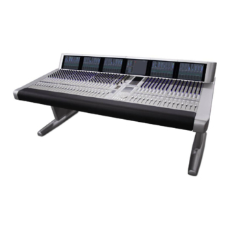
Euphonix System 5 Installation Guide List of Figures Typical Room and Equipment Layout for System 5 ............20 System 5 Console ......................20 Console Dimensions - Top ....................21 Console Dimensions - Side ....................21 CM40x Module Dimensions .....................22 One- and Two-frame Systems ..................23 Three-frame System ......................24... - Page 6 Euphonix System 5 Installation Guide 3-17 SH612 Studio Hub ......................48 3-18 AM713 Front Panel ......................49 3-19 AM713 Rear Panel ......................50 3-20 MA703 Front Panel ......................52 3-21 MA703 Rear Panel ......................53 3-22 DM714 Front Panel ......................55 3-23 DM714 Rear Panel ......................56 3-24 DM714 Parallel AES/EBU Digital Inputs: Female DB-25 ..........57...
- Page 7 List of Tables DF64 Requirements ...................... 14 Summary of System 5 Components ................16 System 5 Components: Dimensions, Power Consumption, Heat Dissipation ....17 Fuse Ratings for System 5 Components ................ 19 Switch Functions ......................36 In 1 Elco 38 Pinout ......................41 In 2 Elco 90 Pinout ......................
- Page 8 Euphonix System 5 Installation Guide viii...
-
Page 9: Chapter 1: System 5 Overview
The DF64 Digital Frame is a rack-mounted unit that performs all audio processing in System 5: dynamics and EQ, mix buses, record buses, aux sends, and monitor buses. Up to four DF64s can be specified in a single system and their DSP can be allocated, using fac- tory-supplied Mixer Model files, to provide different numbers of buses and channels for each project. -
Page 10: Analog And Digital I/O
Euphonix System 5 Installation Guide System 5 Overview Inputs System 5 inputs may be mono, stereo, or any format up to 7.1, which means that a single input may use one to eight logical channels. Physical Faders Each CM408 Eight-channel Module contains eight physical faders. Each fader can control two inputs using a Swap button that switches the fader between the Swap and Main inputs. -
Page 11: Mic Inputs
Digital Sync A high quality digital sync source is required for the System 5 console. Some facilities may already have a digital master clock or house reference in place but others may require one. Euphonix has tested several digital sync generators and distribution amplifiers and can supply... -
Page 12: System Control Connections
Euphonix System 5 Installation Guide System 5 Overview We recommend following these guidelines: • It is important to minimize the timing differences between signal paths to avoid cumulative timing errors. It is good system engineering practice to send sync signals to all system components from one source. - Page 13 Euphonix System 5 Installation Guide System 5 Overview Firewire Each DF64 Digital Frame requires an PC254d Digital Pilot computer. These computers re- quire no user interaction and configure the individual DF64s on startup. Each are connected to their respective DF64s via firewire.
-
Page 14: Estimating System Requirements
This section helps estimate the system requirements for a particular installation. Contact a Euphonix representative for an exact specification. Use following categories to determine the System 5 components necessary for your studio. Most of the studio details considered here are relevant to any digital mixing system. -
Page 15: I/O Specification
Euphonix System 5 Installation Guide System 5 Overview I/O Specification When considering I/O requirements, count the number of analog and AES/EBU inputs and outputs required to hook up all equipment and auxiliary panels for extra equipment. Do not specify I/O from the console perspective. For example, it is not efficient to specify one an- alog input and one analog output to be used as an insert point for each channel input. -
Page 16: Summary Of System 5 Components
Euphonix System 5 Installation Guide System 5 Overview Table 1-2 Summary of System 5 Components Component Function Number Notes CM401 Ethernet devices. CM401 includes a Master Module These two modules make up the center section 1 of each TB Mic and expansion port for TB of the S5 console. -
Page 17: Chapter 2: Interconnecting System Components
Chapter 2: Interconnecting System Components This chapter summarizes technical information for System 5’s components, including size, weight, power consumption, cooling, and fuse requirements and shows their interconnections. To plan an installation, examine Figure 2-1 to learn about suggested equipment locations. - Page 18 Euphonix System 5 Installation Guide Interconnecting System Components 3.5” 17”/432 mm ML530 18.5” 17 lb 89 mm (19”/483 mm 100 W 345 BTU/hr Mic/Line Interface 470 mm 7.7 kg faceplate) 3.5” 17”/432 mm SC262 22” 23 lb 89 mm (19”/483 mm...
-
Page 19: Fuse Ratings For System 5 Components
Euphonix System 5 Installation Guide Interconnecting System Components Table 2-2 Fuse Ratings for System 5 Components How to Change Component 100/115/120 VAC 220/230/240 VAC Voltage Setting CM401 T5 A T5 A autoranging CM402 T5 A T5 A autoranging CM403 T5 A... -
Page 20: Typical Room And Equipment Layout For System 5
Euphonix System 5 Installation Guide Interconnecting System Components Typical Room and Equipment Layout for System 5 Figure 2-1 Typical Room and Equipment Layout for System 5 Typical Console Layout CM424 Producer’s Three CM408 CM402 and CM401 CM403 Film and Three CM408 CM424 Producer’s... -
Page 21: Console Dimensions
Euphonix System 5 Installation Guide Interconnecting System Components Console Dimensions 72.0 41.0 Figure 2-3 Console Dimensions - Top 30.5 39.5 29.5 24.2 Figure 2-4 Console Dimensions - Side... -
Page 22: Cm40X Module Dimensions
Euphonix System 5 Installation Guide Interconnecting System Components 1.75 2.43 120.0 9.12 9.69 24.63 60.0 100.0 1.61 3.08 2.49 29.52 11.96 33.65 Figure 2-5 CM40x Module Dimensions... -
Page 23: Suggested Rack Elevations
Euphonix System 5 Installation Guide Interconnecting System Components Suggested Rack Elevations Figure 2-6 One- and Two-frame Systems... -
Page 24: Three-Frame System
Euphonix System 5 Installation Guide Interconnecting System Components Leave Open SH612 (Studio Hub) EH 224 (EuCon Hub) SH612(Studio Hub) SC262(System PC) Leave Open TT007 MIDI Interface PC254i (Interface Pilot) Frame #1 PC254d (Digital Pilot) PC254d (Digital Pilot) PC254d (Digital Pilot) -
Page 25: Audio Hookup
Euphonix System 5 Installation Guide Interconnecting System Components Audio Hookup Microphone ML530 OUTPUTS INPUTS AM713 1-12 48 Analog 48 Analog 13-24 Studi o Mic Lines ML530 OUTPUTS AM713 INPUTS 48 Analog 1-12 1-48 13-24 Mic Line Interface Analog to MADI... -
Page 26: Synchronization Hookup
Euphonix System 5 Installation Guide Interconnecting System Components Synchronization Hookup OUTPUTS INPUTS AM713 ML530 1-12 W/C In 13-24 Maximum Cable Distances: OUTPUTS AM713 Word: 165 ft (50 m) INPUTS ML530 1-12 W/C In 13-24 Mic Line Interface Analog to MADI... -
Page 27: Madi Hookup
Euphonix System 5 Installation Guide Interconnecting System Components MADI Hookup Device Outputs Device Inputs One DF64 with 11 DSP Cards MADI Inputs MADI Outputs SH612 MADI Inputs MADI Outputs DF64 9 10 11 MADI Inputs MADI Outputs MA703 MADI to Analog... -
Page 28: Madi Hookup For Two Df64 Cores And One Sh612 Studio Hub
Euphonix System 5 Installation Guide Interconnecting System Components Device Outputs Device Inputs Two DF64s MADI Inputs MADI Outputs SH612 MADI Inputs MADI Outputs 10 11 12 9 10 11 12 DF64 MADI Inputs MADI Outputs MA703 MADI to Analog Converter... -
Page 29: Madi Hookup For Three Df64 Cores And Two Sh612 Studio Hubs
Euphonix System 5 Installation Guide Interconnecting System Components Device Outputs Three DF64s 8 9 10 11 12 MADI Inputs SH612 #1 MADI Outputs 8 9 10 11 12 DF64 MADI Inputs MA703 MADI to MADI Outputs Analog Converter for MC524... -
Page 30: Madi Hookup For Four Df64 Cores And Two Sh612 Studio Hubs
Euphonix System 5 Installation Guide Interconnecting System Components Device Outputs Four DF64s 8 9 10 11 12 MADI Inputs SH612 #1 MADI Outputs 8 9 10 11 12 DF64 MADI Inputs MA703 MADI to MADI Outputs Analog Converter for MC524... -
Page 31: Control Hookup
Euphonix System 5 Installation Guide Interconnecting System Components Control Hookup ESBus Lynx Studio Hub Sony 9-pi n SH 612 LT C Devices RS422 CONTROL Up to six additional Mic/Line Interfaces TT007 OUTPUTS INPUTS ML530 1-12 13-24 MIDI Port #2 Maximum Distances... - Page 32 Euphonix System 5 Installation Guide Interconnecting System Components...
-
Page 33: Chapter 3: System 5 Components
Euphonix System 5 Installation Guide Chapter 3: System 5 Components This chapter discusses the System 5 components and all connectors necessary for operation. Pinouts for user-wired connections are shown for each component, along with the cables and connectors provided by Euphonix. -
Page 34: Fc631, Mm641, And Sp661 Cards
Euphonix System 5 Installation Guide System 5 Components Euphonix Euphonix Euphonix MADI Inputs AES Sync Word Sync MADI Outputs FireWire Chassis ID Sync Source DSP Activity AES Word Int MADI Input OK 44.1 48 Custom Select Locked Active Mute Mute... -
Page 35: Fc631 Frame Controller
This card has no connections. System 5 Console The System 5 Console consists of several modular components: the CM401 and CM402 (console center section), the CM408 (contains eight physical faders and controls), the CM403 (contains the joystick panner panel and film monitor panel), and the CM409HTP Track Panner Module. -
Page 36: Cm401 Expansion Port: Db-25 Female Pinout
Euphonix System 5 Installation Guide System 5 Components Pin # Signal LED 1 output (active low) Switch 1 input (active high) LED 3 output (active low) Switch 3 input (active high) LED 5 output (active low) Switch 5 input (active high) -
Page 37: Sc262 System Computer
Euphonix System 5 Installation Guide System 5 Components SC262 System Computer POWERRESET Figure 3-5 SC262 Front and Rear Panels VGA Connector (DA-15): Main video monitor connection. Keyboard (PS/2): Main keyboard connection. Mouse (PS/2): Main trackball connection. Serial Port 1 (DE-9): Touchscreen control connection. -
Page 38: Pc254D Digital Pilot Computer
Euphonix System 5 Installation Guide System 5 Components PC254d Digital Pilot Computer DIGITAL PILOT COMPUTER 254d Figure 3-6 PC254d Front and Rear Panels IEEE 1394 Ports (3 6-pin IEEE 1394 connectors): Connect any port to IEEE 1394 con- nector on the FC631 card in the respective DF64 via provided IEEE 1394 cables (Firewire). -
Page 39: Pc254I Interface Computer
Euphonix System 5 Installation Guide System 5 Components PC254i Interface Computer INTERFACE PILOT COMPUTER 254i Figure 3-7 PC254i Front and Rear Panels Parallel Port (DB-25): Currently unused.. TCC Main Port (Lower DC-62HD): Connect TCC breakout cable (provided) to this port. This cable breaks out to four DB-15 connectors that provide control hookup for the MC524 Monitor Interface and three ML530 Mic/Line Interfaces. -
Page 40: Mc524 Monitor Interface
Listen pre, two Talk Back pre and two Solo channels. Output cable fans out to eight male XLRs. Control (DA-15): Input for digital control signal from Digital Pilot (Euphonix TCC bidi- rectional serial protocol). All patching, switching, and gain controls are communicated via this connection as well as MC524 IP address. -
Page 41: Input/Output Connections
Euphonix System 5 Installation Guide System 5 Components Input/Output Connections Table 3-2 In 1 Elco 38 Pinout Crk # Designator 24 X 32 High Talk 1 Talk 2 Listen 1 Listen 2 Listen 3 Listen 4 Figure 3-9 Elco 38 Connector... -
Page 42: Elco 90 Connector
Euphonix System 5 Installation Guide System 5 Components Table 3-3 In 2 Elco 90 Pinout Crk # Designator 24 X 32 High Cntrl Rm (L) Cntrl Rm (C) Cntrl Rm (R) Cntrl Rm (Sl) Cntrl Rm (Sr) Cntrl Rm (B) -
Page 43: Elco 90 Connector
Euphonix System 5 Installation Guide System 5 Components Table 3-4 Out 1 Elco 90 Pinout Crk # Designator 24 X 32 High BO11 Mon A (L) BO12 Mon A (C) BO17 Mon A (R) BO18 Mon A (Sl) BO19 Mon A (Sr) -
Page 44: Elco 90 Connector
Euphonix System 5 Installation Guide System 5 Components Table 3-5 Out 2 Elco 90 Pinout Crk # Designator 24 X 32 High BO31 Solo L BO32 Solo R Talk 1 Talk 2 Listen 1 Listen 2 Listen 3 Listen 4... -
Page 45: Db-25 Connector
Euphonix System 5 Installation Guide System 5 Components Table 3-6 Out 3 DB-25 Pinout Crk # Designator 24 X 32 High Solo L Solo R 10 9 8 Figure 3-13 DB-25 Connector... -
Page 46: Ml530 Mic/Line Interface
Euphonix System 5 Installation Guide System 5 Components ML530 Mic/Line Interface MIC LINE INTERFACE OUTPUTS INPUTS ML530 1-12 CONTROL 13-24 Figure 3-14 ML530 Front and Rear Panels Inputs (two 38-pin ELCO sockets): A total of 24 microphone inputs are received on two 38-pin ELCO connectors (connectors and pins provided). -
Page 47: Ml530 In 1/In 2 Pinout: Elco 38 Socket
Euphonix System 5 Installation Guide System 5 Components Signal Wiring Instruction & Description Mic In 1 / Mic In 13 From studio Mic 1 / 13 Mic In 2 / Mic In 14 From studio Mic 2 / 14 Mic In 3 / Mic In 15... -
Page 48: Sh612 Studio Hub
Power Connectors (IEC): Accepts two standard IEC power cords (provided). Two autorang- ing switching supplies accept voltages between 100–240 VAC, 50–60 Hz. NOTE: The connections described above pertain only to a System 5 console config- uration. The other connections on the SH612 are used when installed with the... -
Page 49: Am713 Analog To Madi Converter
Euphonix System 5 Installation Guide System 5 Components AM713 Analog to MADI Converter Front Panel Figure 3-18 AM713 Front Panel Signal Strength LEDs: Each of the 28 channels has a four-segment LED that represents the following signal levels: -42 dB, -18 dB, -6 dB (green), -0.05 dB (red). -
Page 50: Rear Panel
Euphonix System 5 Installation Guide System 5 Components Rear Panel Figure 3-19 AM713 Rear Panel Input Voltage Selector: This red switch allows operation in either 100/110/115 VAC or 220/230/240 VAC environments. A fuse must also be changed for 220/230/240 VAC op- eration. - Page 51 Euphonix System 5 Installation Guide System 5 Components MADI Out (BNC): Outputs the digital audio signal. • 1–24: Analog inputs • 25–26: Aux analog inputs • 27–28: Aux digital inputs NOTE: 28 channels are always transmitted; dual channels are not used.
-
Page 52: Ma703 Madi To Analog Converter
Euphonix System 5 Installation Guide System 5 Components MA703 MADI to Analog Converter Front Panel Figure 3-20 MA703 Front Panel Signal Strength LEDs: Each of the 28 channels has a four-segment LED that represents the following signal levels: -42 dB, -18 dB, -6 dB (green), -0.05 dB (red). -
Page 53: Rear Panel
Euphonix System 5 Installation Guide System 5 Components Rear Panel Figure 3-21 MA703 Rear Panel Input Voltage Selector: This red switch allows operation in either 100/110/115 VAC or 220/230/240 VAC environments. A fuse must also be changed for 220/230/240 VAC operation. - Page 54 Euphonix System 5 Installation Guide System 5 Components MADI In (BNC): Digital audio signal input. • 1–24: analog outputs • 25–26: aux analog outputs • 27–28: aux digital outputs.
-
Page 55: Dm714 Aes/Ebu To Madi Converter
Euphonix System 5 Installation Guide System 5 Components DM714 AES/EBU to MADI Converter Front Panel Figure 3-22 DM714 Front Panel Signal Strength LEDs: Each of the 28 channels has a four-segment LED that represents the following signal levels: -42 dB, -18 dB, -6 dB (green), -.05 dB (red). -
Page 56: Rear Panel
Euphonix System 5 Installation Guide System 5 Components Manual Selection Buttons: The button below each Sample Rate LED row manually selects the Sample Rate Source. The DM714 also allows manual selection of the Sample Rate. Power Switch: On/Off switch. Rear Panel... -
Page 57: Dm714 Parallel Aes/Ebu Digital Inputs: Female Db-25
Euphonix System 5 Installation Guide System 5 Components Word Out (BNC): Outputs a Word clock signal synchronized to the Sample Rate Source. In the presence of an external Word clock input, this connector provides a regenerated ver- sion of that input signal. Without an external sample rate source, this connector outputs the internally generated clock signal. -
Page 58: Md704 Madi To Aes/Ebu Converter
Euphonix System 5 Installation Guide System 5 Components MD704 MADI to AES/EBU Converter Front Panel Figure 3-25 MD704 Front Panel Signal Strength LEDs: Each of the 28 channels has a four-segment LED that represents the following signal levels: -42 dB, -18 dB, -6 dB (green), -.05 dB (red). -
Page 59: Rear Panel
Euphonix System 5 Installation Guide System 5 Components Rear Panel Figure 3-26 MD704 Rear Panel Input Voltage Selector: This red switch allows operation in either 100/110/115 VAC or 220/230/240 VAC environments. A fuse must also be changed for 220/230/240 VAC op- eration. -
Page 60: Dm704 Parallel Aes/Ebu Digital Outputs: Female Db-25
Euphonix System 5 Installation Guide System 5 Components MADI In (BNC): Digital audio signal input. • 1–24: main digital outputs • 25–26: aux analog outputs • 27–28: aux digital outputs Bit-Depth Reduction: Sets the resolution to 16, 20, or 24 bits for the main AES/EBU channels. -
Page 61: Fc726 Format Converter
MADI A In 1 / MADI A Out 1 (two BNC): The MADI A In/Out Ports interface with non- Euphonix MADI devices. At 48 kHz, MADI A provides 56 channels of 24-bit audio; at 96 kHz, 28 channels of 24-bit audio channels (cable not provided). - Page 62 Euphonix System 5 Installation Guide System 5 Components SDIF-2 or Slave Clock In (BNC): This connector can receive either an SDIF or Slave Clock Sync signal (the FC726 automatically detects the signal type). An SDIF device must send a Word Sync signal to this connector to interface properly. Slave Clock is a sync signal (commonly implemented in Pro Tools systems and referred to as a super-clock) that runs at 256 times the sample rate.
-
Page 63: Aes/Ebu Db-25 Pinout
Euphonix System 5 Installation Guide System 5 Components Table 3-7 AES/EBU DB-25 Pinout Description Pin 1 Pin 2 Channel 1 / 2 In (COLD) Pin 3 Channel 3 / 4 In (GND) Pin 4 Channel 3 / 4 In (HOT) -
Page 64: Common Dd-50 Connector Pinout And Usage With Third-Party Devices
Euphonix System 5 Installation Guide System 5 Components Table 3-8 Common DD-50 Connector Pinout and Usage With Third-party Devices Common Connector (DB50 Female) SDIF usage TDIF usage ProDigi usage ADAT usage ProTools Pin # 1 In 1+ In 1+ In 1+... -
Page 65: Fc726 Tdif Cable Wiring Specification
Euphonix System 5 Installation Guide System 5 Components Table 3-9 FC726 TDIF Cable Wiring Specification Connector Pin Connection Description 1 NC 2 J2-1 In 1/2 3 NC 4 J2-2 In 3/4 5 NC 6 J2-3 In 5/6 7 NC 8 J2-4... -
Page 66: Fc726 Pro Tools Cable Wiring Specification
Euphonix System 5 Installation Guide System 5 Components Table 3-10 FC726 Pro Tools Cable Wiring Specification Connector Pin Connection Description In 1/2+ 1 J2-17 In 1/2- 2 J2-42 In 3/4+ 3 J2-16 In 3/4- 4 J2-41 In 5/6+ 5 J2-1... -
Page 67: Fc726 Sdif Cable Wiring Specification
Euphonix System 5 Installation Guide System 5 Components Table 3-11 FC726 SDIF Cable Wiring Specification Connector Pin Connection Description In 1+ 1 J4-2 In 1- 2 J4-1 In 3+ 3 J4-6 In 3- 4 J4-5 In 5+ 5 J4-10 In 5-... -
Page 68: Gp132
Tally inputs accept 5–24 VDC/AC. (Contact Euphonix Customer Service before applying over 24 V.) The relays are rated at 500 mA maximum; an additional driver circuit is re- quired to drain more current. -
Page 69: Midi Connections
Euphonix System 5 Installation Guide System 5 Components MIDI Connections Connect the GP132’s MIDI ports to Port 2 (In and Out) on the console’s MIDI Interface. Up to four GP132s can be connected (ins and outs) to ports 2–5. Input and Output Connections... -
Page 70: Gp132 Inputs
Euphonix System 5 Installation Guide System 5 Components Table 3-13 GP132 Inputs 3,6,9,12,14, Common Common Common Common 17,20,23 WARNING: If power fails on the GP132, none of the relays will function. After restoring power, the GP132 resets ALL relays. -
Page 71: Tt007
Setup Connect the IEC power cable (included) to your studio power. Then connect MIDI Port 2 In and Out on the TT007 to MIDI Port 1 In and Out on the System 5 MIDI Interface. Capabilities The TT007 is an optional rack-mount device that provides machine control for all Eu- phonix consoles. -
Page 72: Using The Tt007
Euphonix System 5 Installation Guide System 5 Components Using the TT007 The TT007’s front panel is very easy to master. Dedicated Port buttons instantly access in- dividual assignments for each machine control Port. Any Port can be defined as a master, controller, or slave. -
Page 73: Index
Euphonix System 5 Installation Guide Index Index Inputs 10 KVM Extender 12 Analog I/O 10 Audio Hookup 25 Layouts 10 CM401 9 CM402 9 Machine Control 13 CM403 9 MC524 Monitor Interface 40 CM408 9 Mic Inputs 11 CM409F 9... - Page 74 Euphonix System 5 Installation Guide Index...
Need help?
Do you have a question about the System 5 and is the answer not in the manual?
Questions and answers