Sign In
Upload
Manuals
Brands
Euphonix Manuals
Music Mixer
Max Air Control surface
Euphonix Max Air Control surface Manuals
Manuals and User Guides for Euphonix Max Air Control surface. We have
5
Euphonix Max Air Control surface manuals available for free PDF download: Operation Manual, Manual, Installation Manual, Control Surface Manual
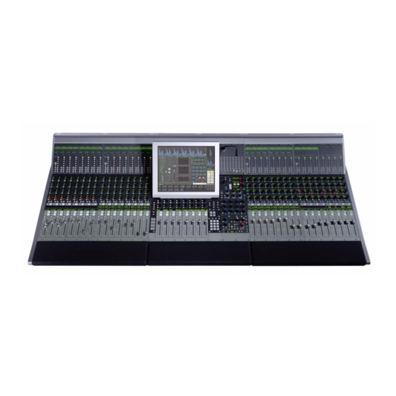
Euphonix Max Air Control surface Operation Manual (188 pages)
Brand:
Euphonix
| Category:
Music Mixer
| Size: 9 MB
Table of Contents
Table of Contents
5
Important Safety Instructions
3
List of Figures
13
Chapter 1: Introduction
17
How to Use this Manual
17
Overview of the System Components
19
DF64 Digital Audio Frame
19
Analog and Digital I/O
19
Typical Max Air Hardware Configuration
20
Control Surface
21
Max Air Control Surface
21
Additional Hardware Components
22
Max Air Startup Sequence
23
Chapter 2: New Features in Version 1.4
25
Chapter 3: Quickstart to Common Tasks
27
Create a Title
27
Initial Router and Patchbay Setup
28
Name Ports
28
Console Sources
28
Assigning the MIC Preamps to Hubs
29
Label Destination Ports and Signals
30
Label Individual Signals
30
Channel to Strip Layout
31
Setting up Stereo Channels Using MF Masters
31
Assign Channels to Strips
32
Busses
33
Create Main Sections and Audio Subgroups
33
Main Section a Signal Flow
35
Route to the Main Sections and Busses
36
Using the 24 Group Busses
37
Meters
38
Setting the Fader Meters on each Strip
38
Screen Meters on the Touchscreen
38
Knobsets
40
Creating a Custom Knobset for Mono Channels
40
Creating a Custom Knobset for Stereo Channels
41
External Device Setup
41
Patching External Devices into the External Inputs
41
Assign External Inputs a Format and a Button
42
Monitors
42
Monitor Routing
42
Save a Default Title
43
Chapter 4: Touchscreen
45
Introduction to the Touchscreen
45
Keyboard Popup
45
Touchscreen Main Menu Buttons
46
Touchscreen Main View
47
Touchscreen Navigation
48
File
49
Projects
49
Drives View
49
Projects View
50
Titles
51
Titles View
51
Operations on the Current Title
52
Save Current Data Popup
52
Current Title Buttons
52
Default Titles
53
Patch
54
Simplified MADI Routing Diagram
54
Destinations and Sources
55
Console I/O
55
Sources and Destinations with Respect to Max Air
55
Console I/O -A and B Inputs View
56
Sources and Destinations Selected
57
Patch Complete
58
Source Input Naming
59
Sources Patched to Channels
59
Cabling
60
Cabling: MADI out Port
61
Cabling: MADI in Port
62
Patching Examples
63
Patch 12 Mics into Channels 25-36
63
Sources View with 12 MIC-Line Sources Selected
63
Selecting Destination Channels
65
MIC Patch Complete
65
Sources Selected
66
Main Bus Send/Return
67
Main Bus Send and Return
67
Monitor Patching
68
Solo Bus and Utility Patching
68
Talkback Signal Patching
68
Busses
69
System
69
Externals
69
Externals View
69
Knobset
70
Knobset View
70
Mixer Model
71
Mixer Model View
71
Preferences
72
Preferences View
72
About
73
Channels
74
Multi Format Masters
74
Control Groups
74
Assign
74
Channels Tabs
74
Assign View
74
Layouts and Snapshots
75
Spill Area
76
Lock Strips
76
Spill Area Function
76
Fader Unity
77
Lock Strips View
77
Fader Unity Popup
77
Status
78
Status View
78
Super Channel
79
Super Channel View
79
Process Order
80
Channel Selector Popup
80
Process Order Popup
80
Main and Group Bus Routing
81
Channel Routing Popup
81
Meters
82
Presets
82
Meters-Presets Popup
82
Screen
83
Meters-Screen Popup with Meters Display
83
Fader
84
Meters-Fader Popup
84
Setup
85
Events
85
Meters-Setup View
85
Chapter 5: Channels and Strips
87
Strips
87
Console Strip and Bus Display with Block Diagrams for Main and Swap Channels
88
Assign Channels to Strips
89
Channel Assign View
89
Channel Control Features
91
Channel Name
91
Channel Selector
91
Main and Swap Channel Displays
91
Fader
92
Strip Fader
92
Meters
93
Status Leds
93
Wave Key
93
Channel on Key
93
Channel Select Key
94
Solo Key
94
Copy and Paste
94
Rotary Knobs
94
Knobset Select Keys
95
Rotary Knob Controls
95
Strip Function Switches
95
In/Out Keys
96
Expand
96
Channel Processing Functions
96
Inputs
96
Mono Input Knobsets
96
Stereo Controls
97
Dynamics
98
Stereo Input Knobsets
98
Dynamics Knobsets
98
EQ Knobsets
99
Filters
100
Filters Knobsets
100
Pan
102
Pan Knobsets
102
Aux Busses
104
Aux Bus Knobset
104
Channel Processor Order and Patch Points
105
Channel Processor Order
105
Insert Point
105
Channel Routing Functions
106
Group Bus Routing
106
Group Bus Routing Knobsets
106
Main Bus Routing
107
Main Section Routing Knobset
107
MIX Minus
108
MIX Minus Processing
108
Chapter 6: Busses
109
Introduction to Max Air Busses
109
Configuring Main and Group Busses
110
Main Bus View
110
Format Selector
111
Group Bus View
111
Format Selector
112
Configuring Aux Busses
114
Aux to Faders
114
Aux Bus Settings View
114
Toggle On/Off
115
Toggle Pre/Post
115
Copy Fader to Aux
115
Copy Aux to Aux
116
Set Unity
116
Toggle Stereo
116
MIX Minus
117
MIX Minus Configuration-Strips View
117
Bus Centric Views
118
Goup Bus View
118
Aux View
118
Group Bus View-Strips
118
Aux Bus View-Channels
119
Main View
120
Main View: A-Channels
120
Bus Masters
121
Main Section Masters
121
CM404 Center Section with Soft Knobs
121
Group and Aux Bus Masters
122
Bus Inserts
122
Chapter 7: Center Section
123
CM404 Master Module
123
Super Channel
124
CM404 Super Channel Controls
124
Assign a Channel to the Super Channel
125
Super Channel: Selected Channel, Pan, Filters, and Input
125
Input Section
126
Pan
126
Filters
127
Insert
127
Super Channel: EQ, Insert
127
Dynamics
128
Fader
128
Super Channel: Dynamics
128
Monitors and Control Room
129
Monitoring Matrix
129
Monitors
130
CM404 Monitor Controls
130
Monitors Setup Popup
130
Control Room
131
Control Room Setup: CR Source
132
Control Room Setup: CR Output
132
Talkback/Slate
134
CM404 Talkback/Slate
134
Talkback
135
Talkback/Slate Setup Popup
135
Listenback
136
Listenback Setup Popup
136
Slate
137
Oscillator
137
Slate Setup Popup
137
CM404 Oscillator
138
Oscillator Setup Popup
138
Solo
139
CM404 solo Controls
139
Solo Setup Popup
139
Solo Mode
140
Solo Level
140
Clear solo
140
Solo Switch Mode
140
Speaker Selection
141
Solo Speaker DIM
141
Solo-Safe
141
Solo Safe Popup
141
Backstop PFL
142
Soft Knobs
142
CM404 Soft Knobs
142
Soft Knob Setup Popup
143
Soft Knobs Setup Popup
143
Center Section Faders
144
CM404 Center Section Faders
144
Keypad
145
CM404 Keypad
145
Keypad Directory Popup
146
Global Functions
147
Global Function Keys
147
Custom Keys
148
Chapter 8: Control Groups and Multi Format Masters
149
Control Groups
149
Create a Control Group
149
Control Groups View
149
Assign Control Group Master to Strip
150
Assign Channels to CG View
150
Multi Format Master Channels
151
Create a Multi Format Master Channel
151
MF Masters View
151
Control Groups or Multi Format Masters
152
Spill
153
Chapter 9: Layouts and Snapshots
155
Layouts
155
Layouts View
155
Store
156
Recall
156
Name
156
Clear
156
Store Layout Popup
156
Snapshots
157
Store
157
Snapshots View
157
Store Snapshot: Strip View
158
Channel View
158
Recall
159
Name
159
Clear
159
Store Snapshot: Channel View
159
Chapter 10: Event System
161
Input Types
162
Output Types
163
Logical Operators
164
Event Configuration Display
165
Event List
165
Event View
165
Input
166
Add Input Event Popup
166
Output
167
Deleting Events
167
GPI Examples
167
Add Output Event Popup
167
Move a Fader to Turn off the Floor Monitors
168
Monitor Off: Inputs Set
169
Action Popup
170
Monitor Off: Outputs Set
170
Move a Fader to Turn on the Floor Monitors
171
Monitor On: Inputs Set
172
Move a Fader to Start a Cart Machine
173
Monitor On: Outputs
173
Machine Popup
174
Move a Fader to Stop a Cart Machine
175
Video Switcher Turns a Specific Camera and Channel on
177
Video Switcher Turns a Specific Camera and Channel off
178
Camera/Channel On: Inputs and Outputs Set
178
Camera/Channel Off: Inputs and Outputs Set
179
Audio Follow Video
180
Audio Follow Video Configuration
180
Advertisement
Euphonix Max Air Control surface Manual (180 pages)
Brand:
Euphonix
| Category:
Other
| Size: 42 MB
Table of Contents
Table of Contents
5
List of Figures
13
Chapter 1: Introduction
17
How to Use this Manual
17
Overview of the System Components
19
Analog and Digital I/O
19
DF66 Supercore
19
Typical Max Air Hardware Configuration
20
Control Surface
21
Max Air Control Surface
21
Additional Hardware Components
22
Max Air Startup Sequence
23
Chapter 2: New Features in Version
25
Chapter 3: Quickstart to Common Tasks
27
Create a Title
27
Initial Router and Patchbay Setup
28
Name Ports
28
Console Sources
28
Assigning the MIC Preamps to Hubs
29
Label Individual Signals
30
Label Destination Ports and Signals
30
Channel to Strip Layout
31
Setting up Stereo Channels Using MF Masters
31
Assign Channels to Strips
32
Busses
33
Create Main Sections and Audio Subgroups
33
Route to the Main Sections and Busses
36
Using the 24 Group Busses
36
Meters
37
Screen Meters on the Touchscreen
37
Setting the Fader Meters on each Strip
37
External Meters Display
38
Knobsets
39
Creating a Custom Knobset for Mono Channels
39
Creating a Custom Knobset for Stereo Channels
40
External Device Setup
40
Patching External Devices into the External Inputs
40
Assign External Inputs a Format and a Button
41
Monitors
42
Monitor Routing
42
Save a Default Title
43
Chapter 4: Touchscreen
45
Introduction to the Touchscreen
45
Keyboard Popup
45
Touchscreen Main Menu Buttons
46
Touchscreen Main View
47
Touchscreen Navigation
48
File
49
Projects
49
Drives View
49
Projects View
50
Titles
51
Titles View
51
Operations on the Current Title
52
Save Current Data Popup
52
Current Title Buttons
52
Default Titles
53
Patch
54
Simplified MADI Routing Diagram
54
Console I/O
55
Destinations and Sources
55
Sources and Destinations with Respect to Max Air
55
Console I/O -A and B Inputs View
56
Sources and Destinations Selected
57
Patch Complete
58
Source Input Naming
59
Sources Patched to Channels
59
Cabling
60
Cabling: MADI out Port
61
Cabling: MADI in Port
62
Patching Examples
63
Patch 12 Mics into Channels
63
Sources View with 12 MIC-Line Sources Selected
63
Selecting Destination Channels
65
MIC Patch Complete
65
Sources Selected
66
Main Bus Send/Return
67
Main Bus Send and Return
67
Monitor Patching
68
Solo Bus and Utility Patching
68
Talkback Signal Patching
68
Busses
69
Externals
69
Externals View
69
System
69
Knobset
70
Knobset View
70
Mixer Model
71
Mixer Model View
71
Preferences
72
Preferences View
72
About
73
Channels
74
Control Groups
74
Multi Format Masters
74
Surface
74
Assign
74
Channels Tabs
74
Assign View
75
Layouts and Snapshots
76
Spill Area
76
Spill Area Function
76
Lock Strips
77
Fader Unity
77
Lock Strips View
77
Status
78
Fader Unity Popup
78
Status View
79
Super Channel
80
Super Channel View
80
Channel Selector Popup
81
Process Order
81
Process Order Popup
81
Channel Routing Popup
82
Main and Group Bus Routing
82
Meters
83
Meters-Presets Popup
83
Presets
83
Meters-Screen Popup with Meters Display
84
Screen
84
Meters-Screen=Ext1 Popup with Meters Display
85
External Meters Display, Fully Configured
86
Fader
87
Meters-Fader Popup
87
Events
88
Meters-Setup View
88
Setup
88
Chapter 5: Channels and Strips
89
Strips
89
Console Strip and Bus Display with Block Diagrams for Main and Swap Channels
90
Assign Channels to Strips
91
Channel Control Features
93
Channel Name
93
Channel Selector
93
Main and Swap Channel Displays
93
Fader
94
Strip Fader
94
Meters
95
Status Leds
95
Channel on Key
95
Wave Key
95
Channel Select Key
96
Copy and Paste
96
Rotary Knobs
96
Solo Key
96
Knobset Select Keys
97
Rotary Knob Controls
97
Strip Function Switches
97
Expand
98
In/Out Keys
98
Channel Processing Functions
98
Inputs
98
Mono Input Knobsets
98
Stereo Input Knobsets
100
Dynamics
101
Dynamics Knobsets
101
EQ Knobsets
102
Filters
103
Filters Knobsets
103
Pan
104
Pan Knobsets
104
Aux Bus Knobset
106
Aux Busses
106
Channel Processor Order and Patch Points
107
Channel Processor Order
107
Insert Point
107
Channel Routing Functions
108
Group Bus Routing
108
Group Bus Routing Knobsets
108
Main Bus Routing
109
Main Section Routing Knobset
109
MIX Minus
110
MIX Minus Processing
110
Chapter 6: Busses
111
Introduction to Max Air Busses
111
Configuring Main and Group Busses
112
Main Bus View
112
Format Selector
113
Group Bus View
113
Format Selector
114
Configuring aux Busses
116
Aux Bus Settings View
116
Aux to Faders
116
Copy Fader to aux
117
Toggle On/Off
117
Toggle Pre/Post
117
Copy aux to aux
118
Level to off
118
Set Unity
118
Toggle Stereo
118
MIX Minus
119
MIX Minus Configuration-Strips View
119
Bus Centric Views
120
Aux View
120
Group Bus View
120
Group Bus View-Strips
120
Aux Bus View-Channels
121
Main View
122
Main View: A-Channels
122
Bus Masters
123
CM404 Center Section with Soft Knobs
123
Main Section Masters
123
Bus Inserts
124
Group and aux Bus Masters
124
Bus Processing
125
Bus Processing Configuration
125
Chapter 7: Center Section
126
CM404 Master Module
126
Super Channel
127
CM404 Super Channel Controls
127
Assign a Channel to the Super Channel
128
Super Channel: Selected Channel, Pan, Filters, and Input
128
Input Section
129
Pan
129
Filters
130
Insert
130
Super Channel: EQ, Insert
130
Dynamics
131
Fader
131
Super Channel: Dynamics
131
Monitors and Control Room
132
CM404 Monitor Controls
133
Monitors
133
Monitors Setup Popup
133
Control Room
134
Control Room Setup: CR Output
135
Control Room Setup: CR Source
135
Talkback/Slate
137
Talkback
138
Listenback
139
Slate
140
Oscillator
140
CM404 Oscillator
141
Oscillator Setup Popup
141
Solo
142
Solo Setup Popup
142
Clear solo
143
Solo Level
143
Solo Mode
143
Solo Switch Mode
143
Solo Safe Popup
144
Solo Speaker DIM
144
Solo-Safe
144
Speaker Selection
144
Backstop PFL
145
Soft Knobs
145
CM404 Soft Knobs
145
Soft Knob Setup Popup
146
Soft Knobs Setup Popup
146
Center Section Faders
147
CM404 Center Section Faders
147
Keypad
148
CM404 Keypad
148
Keypad Directory Popup
149
Global Functions
150
Global Function Keys
150
Custom Keys
151
Chapter 8: Control Groups and Multi Format Masters
152
Control Groups
152
Create a Control Group
152
Control Groups View
152
Assign Control Group Master to Strip
153
Assign Channels to CG View
153
Multi Format Master Channels
154
Create a Multi Format Master Channel
154
MF Masters View
154
Control Groups or Multi Format Masters
155
Spill
156
Chapter 9: Layouts and Snapshots
157
Layouts
157
Layouts View
157
Clear
158
Name
158
Recall
158
Store
158
Store Layout Popup
158
Snapshots
159
Snapshots View
159
Store
159
Store Snapshot: Strip View
160
Clear
161
Name
161
Recall
161
Store Snapshot: Channel View
161
Chapter 10: Scene Automation
162
Scene List
162
Scenes
162
Scene Automation Operations View
162
Scene Menu
163
Add Scene
163
Insert Scene
163
Delete Scene
163
Take
163
Finish
164
Previous and Next
164
Chapter 11: Event System
165
Input Types
166
Output Types
167
Logical Operators
168
Event Configuration Display
169
Event List
169
Event View
169
Input
170
Add Input Event Popup
170
Output
171
Deleting Events
171
Event Trigger on Title Load
171
Add Output Event Popup
171
GPI Examples
172
Creating an "On-Air" Tally
172
On-Air Tally off
174
On-Air Tally on
174
Using a Channel Strip to Control a Cart Machine
175
Cart Start
176
Cart Stop
176
Audio Follow Video
177
Audio Follow Video Configuration
177
Euphonix Max Air Control surface Manual (82 pages)
Brand:
Euphonix
| Category:
Other
| Size: 24 MB
Table of Contents
Table of Contents
5
List of Figures
7
Chapter 1: Max Air Overview
10
Introduction to Max Air
10
Typical Console Layout
10
Digital Signal Processing
11
Analog and Digital I/O
11
Microphone Inputs
12
Modular I/O
13
Monitoring
13
Power
13
Digital Sync
13
System Control Connections
14
Estimating System Requirements
15
Number of DF66 DSP Line Cards
15
Number of CM416 16-Channel Sections
15
I/O Specification
15
DF66 Requirements
15
Summary of Euphonix "Classic" MADI Converters
16
Summary of Euphonix Modular I/O
16
Summary of Max Air Components
17
Chapter 2: Interconnecting System Components
18
Component Specifications
19
Max Air Components: Dimensions, Power Consumption, Heat Dissipation
19
Maximum Cable Lengths
20
Typical Max Air Room and Equipment Layout
23
Console Dimensions
24
Max Air Top Dimensions
24
Max Air Side Dimensions
24
CM416 Bottom Dimensions
25
CM404 Bottom Dimensions
25
Audio Hookup
26
Audio Hookup for Modular I/O
27
Synchronization Hookup
28
Synchronization Details
29
Recommended Sync Distribution Method
29
Recommended Digital Sync Generators
30
Recommended Distribution Amplifiers
30
MADI Hookup
31
MADI Hookup: One DF66 Core, 1 or >1 DSP Line Cards
31
Control Hookup
33
Chapter 3: Max Air Components
34
DF66 Supercore
34
DF66 Super Core Front and Rear Panels
34
SP662, 6 X 6 Bridge, and Sync Cards
35
Sync Card
36
X 6 Bridge Card
36
SP662 DSP Line Card
36
MADI I/O DSP Line Card Cable
36
SNMP Card
37
Max Air Console
38
CM404 Rear Panel
38
CM416 Rear Panel
38
Ferrite
39
SC263 System Computer
40
SC263 Front and Rear Panels
40
MC524 Monitor Interface
42
MC524 Front and Rear Panels
42
Input/Output Connections
43
Elco 38 Connector
43
In 1 Elco 38 Pinout
43
Elco 90 Connector
44
In 2 Elco 90 Pinout
44
Elco 90 Connector
45
Out 1 Elco 90 Pinout
45
Elco 90 Connector
46
Out 2 Elco 90 Pinout
46
Out 3 DB-25 Pinout
47
DB-25 Connector
47
ML530 MIC/Line Interface
48
ML530 Front and Rear Panels
48
ML530 in 1/In 2 Pinout: Elco 38 Socket
49
ML530 out 1/Out 2 Pinout: Elco 38 Socket
49
CO600 Changeover Switch
50
AM713 Analog to MADI Converter
51
AM713 Front Panel
51
AM713 Rear Panel
52
MA703 MADI to Analog Converter
54
MA703 Front Panel
54
MA703 Rear Panel
55
DM714 AES/EBU to MADI Converter
57
DM714 Front Panel
57
DM714 Rear Panel
58
DM714 Parallel AES/EBU Digital Inputs: Female DB-25
59
MD704 MADI to AES/EBU Converter
60
MD704 Front Panel
60
MD704 Rear Panel
61
FC726 Format Converter
63
FC726 Front and Rear Panels
63
AES/EBU DB-25 Pinout
65
Common DD-50 Connector Pinout and Usage with Third-Party Devices
66
FC726 TDIF Cable Wiring Specification
67
FC726 SDIF Cable Wiring Specification
68
Modular I/O
69
Modules
70
Modular I/O Modules
70
More Modular I/O Modules
72
Frames
73
AD914 RJ-45 Pinout
73
Frame Summary
75
I/O Module Summary
75
Input and Output Connections
76
TT002 Card and Panels
76
TT002 P1 Connections and Pinouts
76
Connection Pinouts (DC-37 GP1 - GP2)
77
GP1 Inputs and Outputs
77
Simplified TT002 GPO and GPI Circuits
78
FT730 Fibertran Fiberoptic Extender
79
FT730 Front Panel
79
FT730 Front Panel Status Leds
79
Rear Panel
80
FT730 Rear Panel
80
Advertisement
Euphonix Max Air Control surface Installation Manual (63 pages)
Brand:
Euphonix
| Category:
Music Mixer
| Size: 4 MB
Table of Contents
Table of Contents
3
List of Figures
5
Chapter 1: Max Air Overview
9
Introduction to Max Air
9
The Max Air Console
9
Typical Console Layout
9
Digital Signal Processing
10
Analog and Digital I/O
10
Microphone Inputs
11
Monitoring
11
Power
11
Digital Sync
11
System Control Connections
12
Estimating System Requirements
13
Number of CM416 16-Channel Sections
13
I/O Specification
13
Summary of Max Air Components
15
Chapter 2: Interconnecting System Components
17
Component Specifications
18
Max Air Components: Dimensions, Power Consumption, Heat Dissipation
18
Fuse Ratings for Max Air Components
19
Typical Max Air Room and Equipment Layout
20
Console Dimensions
21
Max Air Top Dimensions
21
Max Air Side Dimensions
21
CM416 Bottom Dimensions
22
CM404 Bottom Dimensions
22
Audio Hookup
23
Synchronization Hookup
24
Synchronization Hookup (Word Clock Shown, AES/EBU Sync May be Used)
24
MADI Hookup
25
MADI Hookup for One DF64
25
MADI Hookup for One DF64 and an Optional SH612 Studio Hub
25
Control Hookup
26
Chapter 3: Max Air Components
27
DF64 Digital Frame
27
DF64 Digital Frame Front and Rear Panels
27
FC631, MM641, and SP661 Cards
28
FC631 Frame Controller
29
MM641 MADI Interface Card
29
SP661 Signal Processor
29
Max Air Console
30
CM404 Rear Panel
30
CM416 Rear Panel
30
SC261 System Computer
31
SC261 Front and Rear Panels
31
Pc253D Digital Pilot Computer
32
Pc253D Front and Rear Panels
32
Pc253I Interface Computer
33
Pc253I Front and Rear Panels
33
MC524 Monitor Interface
34
MC524 Front and Rear Panels
34
Input/Output Connections
35
Elco 38 Connector
35
In 1 Elco 38 Pinout
35
Elco 90 Connector
36
In 2 Elco 90 Pinout
36
Elco 90 Connector
37
Out 1 Elco 90 Pinout
37
Elco 90 Connector
38
Out 2 Elco 90 Pinout
38
DB-25 Connector
39
Out 3 DB-25 Pinout
39
ML530 MIC/Line Interface
40
ML530 Front and Rear Panels
40
ML530 in 1/In 2 Pinout: Elco 38 Socket
41
ML530 out 1/Out 2 Pinout: Elco 38 Socket
41
SH612 Studio Hub (Optional)
42
SH612 Studio Hub
42
AM713 Analog to MADI Converter
43
Front Panel
43
AM713 Front Panel
43
Rear Panel
44
AM713 Rear Panel
44
MA703 MADI to Analog Converter
46
Front Panel
46
MA703 Front Panel
46
Rear Panel
47
MA703 Rear Panel
47
DM714 AES/EBU to MADI Converter
49
Front Panel
49
DM714 Front Panel
49
Rear Panel
50
DM714 Rear Panel
50
DM714 Parallel AES/EBU Digital Inputs: Female DB-25
51
MD704 MADI to AES/EBU Converter
52
Front Panel
52
MD704 Front Panel
52
Rear Panel
53
MD704 Rear Panel
53
DM704 Parallel AES/EBU Digital Outputs: Female DB-25
54
FC727/726 Format Converter
55
FC727/726 Front and Rear Panels
55
AES/EBU DB-25 Pinout
57
Common DB-50 Connector Pinout and Usage with Third-Party Devices
58
FC727 TDIF Cable Wiring Specification
59
FC727 Pro Tools Cable Wiring Specification
60
FC727 SDIF Cable Wiring Specification
61
Gp132
62
Input and Output Connections
62
GP132 Front and Rear Panels
62
GP132 Input and Output Connections
62
Connector Pinouts (DB-25 RT1-RT4)
63
GP132 Outputs
63
GP132 Inputs
63
Euphonix Max Air Control surface Control Surface Manual (20 pages)
Brand:
Euphonix
| Category:
Music Mixer
| Size: 2 MB
Table of Contents
Important Safety Instructions
3
Table of Contents
5
System Startup Sequence
7
Typical Console Layout
7
Description
7
Overview
7
CM404 Rear Panel
8
CM416 Rear Panel
8
Cm404
8
Cm416
8
Self Test Procedure
9
Initiating Self Test
9
Switch and Knob Test
9
Control Surface Self-Test Keys
9
LED Test
10
Fader Test
10
Display Test
11
Memory Test
11
Selecting and Adjusting the Onscreen Display
12
Touchscreen Alignment
13
Changing the CM416 ID
15
Changing the ID of a CM416 Module
15
System Ethernet IP Addresses
15
Technical Specifications
16
Power
16
Environmental Requirements
16
Dimensions
17
Side Dimensions
17
CM416 Bottom Dimensions
17
CM404 Bottom Dimensions
18
Max Air Top Dimensions
18
User Reference
19
Internal Components
19
Fans
20
Advertisement
Related Products
Euphonix S5 Surface Modules
Euphonix SH612
Euphonix S5 CM401
Euphonix S5 CM402
Euphonix S5 CM403
Euphonix S5 CM408
Euphonix S5 CM411
Euphonix SL156
Euphonix SC263
Euphonix Avid SC264
Euphonix Categories
Music Mixer
Music Equipment
Recording Equipment
Media Converter
Software
More Euphonix Manuals
Login
Sign In
OR
Sign in with Facebook
Sign in with Google
Upload manual
Upload from disk
Upload from URL