Lightware UBEX-MMU-X200 User Manual
Av over ip multimedia extender
Hide thumbs
Also See for UBEX-MMU-X200:
- Installation and network setup manual (36 pages) ,
- User manual (201 pages)
Table of Contents
Advertisement
Quick Links
User's Manual
Matrix Application Mode
UBEX-MMU-X200
UBEX-PRO20-HDMI-F100
UBEX-PRO20-HDMI-F110
UBEX-PRO20-HDMI-R100 2xMM-2xDUO
UBEX-PRO20-HDMI-R100 2xMM-QUAD
UBEX-PRO20-HDMI-R100 2xSM-2xDUO
UBEX-PRO20-HDMI-R100 2xSM-QUAD
UBEX-PRO20-HDMI-R100 2xSM-BiDi-DUO
AV Over IP Multimedia Extender
v2.0
11-11-2020
Advertisement
Table of Contents
Troubleshooting

Related Manuals for Lightware UBEX-MMU-X200


Summary of Contents for Lightware UBEX-MMU-X200
- Page 1 User’s Manual Matrix Application Mode UBEX-MMU-X200 UBEX-PRO20-HDMI-F100 UBEX-PRO20-HDMI-F110 UBEX-PRO20-HDMI-R100 2xMM-2xDUO UBEX-PRO20-HDMI-R100 2xMM-QUAD UBEX-PRO20-HDMI-R100 2xSM-2xDUO UBEX-PRO20-HDMI-R100 2xSM-QUAD UBEX-PRO20-HDMI-R100 2xSM-BiDi-DUO AV Over IP Multimedia Extender v2.0 11-11-2020 ...
- Page 2 series – Matrix Application Mode – User's Manual Important Safety Instructions Waste Electrical & Electronic Equipment Common Safety Symbols WEEE Class I apparatus construction. Symbol Description This marking shown on the product or its literature, This equipment must be used with a mains power system with a indicates that it should not be disposed with other protective earth connection.
- Page 3 The following symbols and markings are used in the document: All presented functions refer to the indicated products. The Lightware Visual Engineering supports green technologies and descriptions have been made during testing these functions in eco-friend mentality. Thus, this document is made for digital usage...
- Page 4 #dhcp This keyword is placed at the DHCP (dynamic IP address) setting in the front panel operation, the Lightware Device Controller (LDC) and the LW3 programmer's reference section. See the list of all hashtag keywords of the document in the...
-
Page 5: Table Of Contents
5.1. Mounting Options - F-series Endpoint Devices ......34 2.2.2. Rear View ..................23 5.10.4. Optional Configuration ..............51 5.1.1. Mounting Bracket V2 ..............34 2.3. Front and Rear View - UBEX-MMU-X200 ........24 5.10.5. Installation and Network Setup Guide for UBEX ......51 5.1.2. Rack Shelf Mounting ..............34 2.3.1. Front View ..................24 5.10.6. System Design Guide for UBEX ........... - Page 6 6.2. Control Features ..............59 7.2. The Layout of the Built-in Web ..........81 8.14. Control Menu ................117 6.2.1. Ethernet Interface ................60 8. SOFTWARE CONTROL - LIGHTWARE DEVICE CONTROLLER ..82 8.14.1. Ethernet Tab ................117 6.2.2. Serial Interface ................60 8.1. Install and Upgrade ..............83 8.14.2. RS-232 Tab .................. 117 6.3. Video Interface ................61...
- Page 7 series – Matrix Application Mode – User's Manual Table of Contents 9.4. The Tree Structure of the UBEX Matrix .........134 9.7.11. Unclaiming an Endpoint ............. 142 9.10.15. Query the Timing Mode............150 9.4.1. The Tree Structure of the MMU ........... 134 9.7.12. Unclaiming All Endpoints ............
- Page 8 series – Matrix Application Mode – User's Manual Table of Contents 9.11.33. Activate Layout ................. 160 9.14.5. Mute/Unmute the Analog Audio Output Port ......167 9.19. Ethernet Port Configuration - Endpoint ......175 9.11.34. Setting the Name of the Layout..........160 9.15. EDID Management ..............168 9.19.1. Enabling the Port ................
- Page 9 14.1.2. UBEX-PRO20-HDMI-F110 ............226 10.3. Installation of LDU2 .............196 14.1.3. UBEX-PRO20-HDMI-R100 series ..........228 10.4. Upgrading of the MMU - Detailed Instructions ....196 14.1.4. UBEX-MMU-X200 ................ 229 10.4.1. Establish Connection ..............196 14.2. Factory Default Settings ............231 10.4.2. Start the LDU2 Application and Follow the Steps ....196 14.2.1. UBEX-PRO20-HDMI-F100 / R100 series........
-
Page 10: Introduction
– Matrix Application Mode – User's Manual I ntroduction Thank you for choosing Lightware’s UBEX families extender. In the first chapter we would like to introduce the device highlighting the most important features in the following sections: ç Description ç... -
Page 11: Description
UBEX-MMU-X200 Matrix Management Unit UBEX-MMU-X200 is a Matrix Management Unit (MMU) for the UBEX AV Over IP optical extender product line. Matrix Management Unit With a standard Ethernet switch installed as a crosspoint, a virtual matrix can be created with UBEX devices connected to the IP network as input and output endpoints. -
Page 12: Box Contents
* For UBEX-PRO20-HDMI-F110 model. 1.3. Optional Accessories INFO: 10GbE singlemode/multimode SFP+ modules can be ordered separately for the UBEX devices. For the details please contact sales@lightware.com. The following items can be purchased optionally for the indicated device. 1.2.2. UBEX-PRO20-HDMI-R100 Series UBEX-PRO20-HDMI-F100 / F110... -
Page 13: Model Comparison
1. Introduction 1. Introduction series – Matrix Application Mode – User's Manual series – Matrix Application Mode – User's Manual 1.4. Model Comparison The available UBEX endpoint models have different features depending on their design. The following table contains the most important differences between the models: Power connector AV transmission interface Video ports... -
Page 14: Features
It displays a traditional inputs can be disabled when non-protected content is extended. crosspoint view of the virtual matrix in the Lightware Device Controller (LDC) software, also displaying the video streams which can be sorted by unique tags for the easy recognition. - Page 15 Open API Open-source API technology at the core makes these Lightware products easy to integrate into third-party systems. Every bit of data in Lightware systems is openly available for higher level management and monitoring systems. Applied F-series endpoint firmware package: v1.5.4 | Applied R-series endpoint firmware package: v1.5.4 | Applied MMU firmware package: v1.3.3 | LDC software: v2.4.2b4...
-
Page 16: Application Modes
Extender Mode - Point-to-point connection between a transmitter and a receiver, or between two transceiver endpoint devices. The user's manual of the UBEX Extender mode can be downloaded from the following link: #extendermode https://lightware.com/media/lightware/filedownloader/file/User-Manual/UBEX_Extender_ UsersManual.pdf ▪ Matrix Mode - Virtual AV matrix with more transmitters, receivers, transceivers, and a Matrix Management Unit (MMU) which controls the AV network. -
Page 17: Corporate Application
1. Introduction 1. Introduction series – Matrix Application Mode – User's Manual series – Matrix Application Mode – User's Manual 1.7.2. Corporate Application Description The UBEX matrix has more endpoint devices which can be UBEX-PRO20-HDMI-F100 UBEX-PRO20-HDMI-F110 models... -
Page 18: Video Wall Application
INFO: RAP-B511 series devices can be ordered separately for the UBEX matrix. For the details please contact sales@lightware.com. Application diagram of Matrix mode - Video wall application Applied F-series endpoint firmware package: v1.5.4 | Applied R-series endpoint firmware package: v1.5.4 | Applied MMU firmware package: v1.3.3 | LDC software: v2.4.2b4... -
Page 19: Product Overview
ç Front and Rear View - F-series Endpoint Devices ç Front and Rear View - R-series Endpoint Devices ç Front and Rear View - UBEX-MMU-X200 Applied F-series endpoint firmware package: v1.5.4 | Applied R-series endpoint firmware package: v1.5.4 | Applied MMU firmware package: v1.3.3 | LDC software: v2.4.2b4... -
Page 20: Front And Rear View - F-Series Endpoint Devices
Front Panel section; Reset button Reboots the device (the same as disconnecting from the power source and ▪ Lightware Device Controller (LDC) software / Built-in website - see the details in the Health Status Tab reconnecting again). section; ▪ LW3 protocol command - see the details in the Dark Mode Setting section. -
Page 21: Rear View
2. Product Overview 2. Product Overview series – Matrix Application Mode – User's Manual series – Matrix Application Mode – User's Manual 2.1.2. Rear View HDMI output ports HDMI output ports with HDMI 2.0 support for sink devices. When the device UBEX-PRO20-HDMI-F100 is configured as transmitter, the both ports operate as local HDMI outputs. -
Page 22: Front And Rear View - R-Series Endpoint Devices
Front panel LCD menu - see the details in the Front Panel section; ▪ ▪ Lightware Device Controller (LDC) software / Built-in website - see the details in the Health Status Tab Reset button Reboots the device (the same as disconnecting from the power source and section;... -
Page 23: Rear View
2. Product Overview 2. Product Overview series – Matrix Application Mode – User's Manual series – Matrix Application Mode – User's Manual 2.2.2. Rear View Neutrik powerCON Neutrik powerCON TRUE1 NAC3MPX-WOT connector accepting 100-240 V, UBEX-PRO20-HDMI-R100 2xMM-QUAD and 2xSM-QUAD AC connector 50 or 60 Hz. -
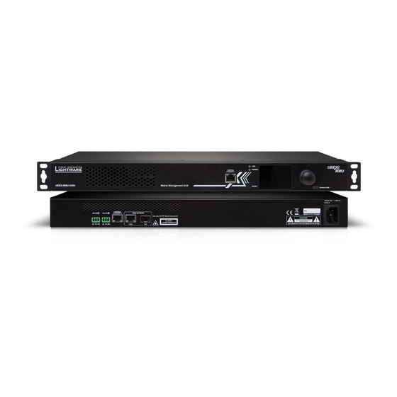
Page 24: Front And Rear View - Ubex-Mmu-X200
2. Product Overview 2. Product Overview series – Matrix Application Mode – User's Manual series – Matrix Application Mode – User's Manual 2.3. Front and Rear View - UBEX-MMU-X200 2.3.2. Rear View 2.3.1. Front View CONTROL ETHERNET 1 Matrix Management Unit... -
Page 25: Front Panel Lcd Menu Operation - Mmu
3. Front Panel LCD Menu Operation - MMU 3. Front Panel LCD Menu Operation - MMU series – Matrix Application Mode – User's Manual series – Matrix Application Mode – User's Manual F ront Panel LCD Menu Operation - MMU This chapter is about the operating of the Matrix Management Unit describing the functions which are available by the front panel controls:... -
Page 26: Introduction
Date format: YYYY-MM-DD TIPS AND TRICKS: The time and date can be set easily in the built- in web or in the Lightware Device Controller software manually or by synchronizing with the local computer. See the details in the System Tab section. -
Page 27: Front Panel Lcd Menu Operation - Endpoints
4. Front Panel LCD Menu Operation - Endpoints 4. Front Panel LCD Menu Operation - Endpoints series – Matrix Application Mode – User's Manual series – Matrix Application Mode – User's Manual F ront Panel LCD Menu Operation - Endpoints This chapter is about the operating of the endpoint device describing the functions which are available by the front panel controls:... -
Page 28: The Tree Structure Of The Lcd Menu
4. Front Panel LCD Menu Operation - Endpoints 4. Front Panel LCD Menu Operation - Endpoints series – Matrix Application Mode – User's Manual series – Matrix Application Mode – User's Manual 4.1. The Tree Structure of the LCD Menu HOME SCREEN HOME SCREEN... -
Page 29: Introduction
The color of the header is blue for the transmitter, white for the receiver, and black with a white stripe for The device label can be modified by the following methods: the transceiver; ▪ Using the Lightware Device Controller (LDC) software - see the details in the Device Information (for TX and ▪... -
Page 30: Ports Menu - Transmitter Operation Mode
4. Front Panel LCD Menu Operation - Endpoints 4. Front Panel LCD Menu Operation - Endpoints series – Matrix Application Mode – User's Manual series – Matrix Application Mode – User's Manual 4.4. Ports Menu - Transmitter Operation Mode 4.5. Ports Menu - Receiver Operation Mode The most important status information of the HDMI input and local output ports... -
Page 31: Ports Menu - Transceiver Operation Mode
4. Front Panel LCD Menu Operation - Endpoints 4. Front Panel LCD Menu Operation - Endpoints series – Matrix Application Mode – User's Manual series – Matrix Application Mode – User's Manual 4.6. Ports Menu - Transceiver Operation Mode 4.6.3. TRX O2 Port The following information is displayed for the local output port:... -
Page 32: System Status Menu
4. Front Panel LCD Menu Operation - Endpoints 4. Front Panel LCD Menu Operation - Endpoints series – Matrix Application Mode – User's Manual series – Matrix Application Mode – User's Manual 4.8. System Status Menu 4.9.2. Application Mode The current application mode (Extender or Matrix) is displayed in this submenu. -
Page 33: Installation
5. Installation 5. Installation series – Matrix Application Mode – User's Manual series – Matrix Application Mode – User's Manual I nstallation The chapter is about the installation of the device and connecting to other appliances, presenting also the mounting options and further assembly steps: ç... -
Page 34: Mounting Options - F-Series Endpoint Devices
INFO: The endpoint device is half-rack sized. To order mounting accessories please contact sales@lightware.com. 5.1.1. Mounting Bracket V2 Mounting bracket V2 gives an opportunity to mount the device to any furniture surface. Fasten the bracket on the side of the unit with the provided screws and fasten it to a stand / board / truss / furniture. -
Page 35: Mounting Options - R-Series Endpoint Devices
Mounting thread on top and on one of the sides for safe and secure installation. Rigging the handles with a safety wire rope is highly recommended for safety reasons. To order mounting accessories please contact sales@lightware.com. (Truss clamp and safety wire rope are not available at sales.) Step 2. - Page 36 5. Installation 5. Installation series – Matrix Application Mode – User's Manual series – Matrix Application Mode – User's Manual ATTENTION! Take care of the mounting direction of the screws! Step 4. As a final step, mount the unit in the rack. Mounting direction of the screws Step 3.
-
Page 37: Rack Shelf Mounting - Mmu
5. Installation 5. Installation series – Matrix Application Mode – User's Manual series – Matrix Application Mode – User's Manual 5.3. Rack Shelf Mounting - MMU 5.4. Electrical Connections Two rack ears are supplied with the product, which are fixed on left and right side with 2x 4 pcs M4 screws. The following sections describe all possible electrical connections of the UBEX endpoint and MMU devices. -
Page 38: Symmetrical Analog Stereo Audio Connector
5. Installation 5. Installation series – Matrix Application Mode – User's Manual series – Matrix Application Mode – User's Manual 5.4.4. RS-232 Connector Neutrik powerCON TRUE1 Connector UBEX R-series endpoint devices contains Neutrik powerCON TRUE1 NAC3MPX-WOT power UBEX-PRO20-HDMI-F110 model and the Matrix Management Unit contains a 3-pole Phoenix connector connector and works with 100 to 240 Volts AC, 50 Hz or 60 Hz power sources. -
Page 39: Hdmi Connector
Does not intermate with CAT6 cable connector NE8MC6-MO and NKE6S* Connector cables. drawing Wiring of LAN Cables Lightware recommends the termination of LAN cables on the basis of TIA/EIA T 568 A or TIA/EIA T 568 B Connector type NO2-4FDW-A NO4FDW-A standards. -
Page 40: Connections
After connecting the device to the network and the MMU: WARNING! User Ethernet is also transmitted over the SFP+ interface so be sure not to create network via Lightware Device Controller (LDC) software - see the details in the Device Map section;... -
Page 41: F-Series Endpoints - Receiver Operation Mode
WARNING! User Ethernet is also transmitted over the SFP+ interface so be sure not to create network loop. ▪ via Lightware Device Controller (LDC) software - see the details in the Device Map section; ▪ via LW3 protocol command - see the details in the Set the Operation Mode section. -
Page 42: F-Series Endpoints - Transceiver Operation Mode
After connecting the device to the network and the MMU: WARNING! User Ethernet is also transmitted over the SFP+ interface so be sure not to create network ▪ via Lightware Device Controller (LDC) software - see the details in the Device Map section; loop. -
Page 43: R-Series Endpoints - Transmitter Operation Mode
5. Installation 5. Installation series – Matrix Application Mode – User's Manual series – Matrix Application Mode – User's Manual 5.5.4. R-series Endpoints - Transmitter Operation Mode Connect the source devices (e.g. PC, Blu-ray player) using the HDMI input 1 HDMI in 2xMM-2xDUO and 2xSM-2xDUO and 2 ports by HDMI cables. -
Page 44: R-Series Endpoints - Receiver Operation Mode
5. Installation 5. Installation series – Matrix Application Mode – User's Manual series – Matrix Application Mode – User's Manual 5.5.5. R-series Endpoints - Receiver Operation Mode 2xMM-2xDUO and 2xSM-2xDUO Local HDMI in Connect the local source devices (e.g. -
Page 45: R-Series Endpoints - Transceiver Operation Mode
5. Installation 5. Installation series – Matrix Application Mode – User's Manual series – Matrix Application Mode – User's Manual 5.5.6. R-series Endpoints - Transceiver Operation Mode Connect the source device (e.g. PC) using the HDMI input 2 port by an HDMI HDMI in 2xMM-2xDUO and 2xSM-2xDUO cable. -
Page 46: Matrix Management Unit (Mmu)
AC power socket. INFO: The USB control function will be added by future firmware update. Connections for the UBEX-MMU-X200 Matrix Management Unit Applied F-series endpoint firmware package: v1.5.4 | Applied R-series endpoint firmware package: v1.5.4 | Applied MMU firmware package: v1.3.3 | LDC software: v2.4.2b4... -
Page 47: Sfp / Sfp+ Slot Connection
Inserting the DAC Cables The UBEX-MMU-X200 Matrix Management Unit has one SFP module slot for the fiber optical connection via Step 1. Push the plug of the DAC cable to one of the SFP / SFP+ port slot of the transmitter to stop. -
Page 48: Fiber Optical Cable Connections
5. Installation 5. Installation series – Matrix Application Mode – User's Manual series – Matrix Application Mode – User's Manual 5.7. Fiber Optical Cable Connections 5.7.3. Connection between Neutrik opticalCON DUO Connectors Affected models: The section describes how to connect the fiber optical cables between two SFP+ modules and between two Neutrik opticalCON connectors in case of F and R-series endpoint devices. -
Page 49: Connection Between The Switch And R-Series Endpoints
5. Installation 5. Installation series – Matrix Application Mode – User's Manual series – Matrix Application Mode – User's Manual 5.8. Connection between the Switch and R-series Endpoints L3 network switches are built with SFP+ slots, the R-series devices are built with Neutrik opticalCON DUO and QUAD fiber optical connections. -
Page 50: Sfp+ Bidi To Neutrik Opticalcon Duo Bidi
5. Installation 5. Installation series – Matrix Application Mode – User's Manual series – Matrix Application Mode – User's Manual ATTENTION! Always be sure that the fiber optical mode of the entire fiber optical equipment (SFP+ Step 3. -
Page 51: Ethernet Switch - Detailed Requirements
For more details about requirements of the network switch please visit our website and download the traffic. The feature allows a network switch to listen in on the IGMP conversation between hosts and application notes for UBEX: routers. https://lightware.com/media/lightware/filedownloader/file/Support-Guide/Installation_and_Network_ IGMPv2 snooping has to be enabled for each LAG in this VLAN. Setup_Guide_for_UBEX.pdf 5.10.4. Optional Configuration... -
Page 52: Startup Of The System
Crosspoint Menu - Video Layer section. ▪ After connecting the device to the UBEX matrix - use the Lightware Device Controller software. See the details in the Device Map section. 5.11.3. Connect to the Matrix Management Unit Establish the connection between the Matrix Management Unit (MMU) and the controller device. -
Page 53: Customize The View Of The Matrix
5. Installation 5. Installation series – Matrix Application Mode – User's Manual series – Matrix Application Mode – User's Manual 5.11.7. Add Tags to the Video Streams Source (Input Stream of a Transmitter or Transceiver) Side 1/01 1/02 More tags can be attached to the streams and devices for the effective searchability. -
Page 54: Set The Video Crosspoint State
5. Installation 5. Installation series – Matrix Application Mode – User's Manual series – Matrix Application Mode – User's Manual 5.11.9. Set the Video Crosspoint State Appereance of the Destination Tile When the selected source is the local input port or the copy of the HDMI out 1, the Set the connections between the 2/02 destination port tiles and the crosspoint tile appear as the following:... -
Page 55: Emulate The Correct Edid
5. Installation 5. Installation series – Matrix Application Mode – User's Manual series – Matrix Application Mode – User's Manual 5.11.13. Emulate the Correct EDID 5.11.14. Set the Scaler and the Frame Rate Converter Emulate the right EDID to the HDMI input ports of the transmitter. -
Page 56: Set The Audio Crosspoint State
5. Installation 5. Installation series – Matrix Application Mode – User's Manual series – Matrix Application Mode – User's Manual 5.11.15. Set the Audio Crosspoint State 5.11.16. Set the Parameters of the Audio Streams Set up the audio crosspoint settings. -
Page 57: Checkpoints For The Seamless Switching
▪ Set the color range: if the color ranges of the signal source devices are different, this setting helps adjusting between the different types. Lightware recommends the following settings for the color range: – If the color range of the signal source devices are the same: set to No conversion (default). -
Page 58: Ubex Concept
6. UBEX Concept 6. UBEX Concept series – Matrix Application Mode – User's Manual series – Matrix Application Mode – User's Manual U BEX Concept The following chapter describes the features of the device with real-life examples. The topics what are described: ç... -
Page 59: The Matrix Management Unit (Mmu)
Serial Interface The UBEX-MMU-X200 can receive control signals from the two serial ports (RS-232 1 and 2), and the two Ethernet ports (Control Ethernet 1 and 2). ATTENTION! The RS-232 port of the F110 endpoint model can be used for controlling third-party devices ATTENTION! The Control Ethernet 1 port (on the front panel) supports 100 Mbps Ethernet only. -
Page 60: Ethernet Interface
MMU or the matrix. The matrix can be configured with the following tools: The matrix can be configured with the following tools: ▪ Lightware Device Controller (LDC) software (details: Software Control - Lightware Device Controller); ▪... -
Page 61: Video Interface
6. UBEX Concept 6. UBEX Concept series – Matrix Application Mode – User's Manual series – Matrix Application Mode – User's Manual 6.3. Video Interface HDMI Output Modes The HDMI output ports of the transmitter are HDMI loop-back ports and can be used as local HDMI outputs. 6.3.1. Transmitter Mode The HDMI output 1 transmits the signal of the HDMI input 1 port, the HDMI output 2 transmits the signal of Port Diagram... -
Page 62: Receiver Mode
6. UBEX Concept 6. UBEX Concept series – Matrix Application Mode – User's Manual series – Matrix Application Mode – User's Manual 6.3.2. Receiver Mode Source Multiplexer (MUX) The source multiplexer (Source MUX) makes available routing more different source signals to the HDMI Port Diagram output ports. -
Page 63: Transceiver Mode
6. UBEX Concept 6. UBEX Concept series – Matrix Application Mode – User's Manual series – Matrix Application Mode – User's Manual 6.3.3. Transceiver Mode The HDMI out 1 transmits the HDMI signal coming from the remote UBEX endpoint. The video stream can be processed in the video processor (it contains scaler, frame rate converter (FRC) and color space converter Port Diagram (CSC) functions). -
Page 64: Bandwidth Limitation
6. UBEX Concept 6. UBEX Concept series – Matrix Application Mode – User's Manual series – Matrix Application Mode – User's Manual 6.3.4. Bandwidth Limitation 6.3.5. The Difference between the Scaler and the FRC - Example Two video streams can be transmitted at the same time from an endpoint device up to 20 Gbps bandwidth. -
Page 65: The Difference Between The Image Positions Of The Scaler
6. UBEX Concept 6. UBEX Concept series – Matrix Application Mode – User's Manual series – Matrix Application Mode – User's Manual 6.3.6. The Difference between the Image Positions of the Scaler The following section helps to understand how the image position settings of the scaler works. Three different image positions are available: stretch, fit and center. -
Page 66: Timing Modes
6. UBEX Concept 6. UBEX Concept series – Matrix Application Mode – User's Manual series – Matrix Application Mode – User's Manual 6.3.7. Timing Modes Application of Timing Mode Settings - Example Technical Background UBEX receivers and transceivers provide two different timing modes on the HDMI outputs: ▪... -
Page 67: Hdmi Signal Transmission - Example
– Matrix Application Mode – User's Manual 6.3.8. HDMI Signal Transmission - Example Crosspoint Settings The best overview of the crosspoint settings is available in the Lightware Device Controller software. The following description based on the software. INFO: See the comprehensive description of the LDC software in the Software Control - Lightware Device Controller chapter. - Page 68 6. UBEX Concept 6. UBEX Concept series – Matrix Application Mode – User's Manual series – Matrix Application Mode – User's Manual Crosspoint Possibilities Stream Search The following table shows the available crosspoint possibilities: Use the Search field to find any stream on the network.
-
Page 69: Video Wall
6. UBEX Concept 6. UBEX Concept series – Matrix Application Mode – User's Manual series – Matrix Application Mode – User's Manual 6.4. Video Wall 6.4.2. Layouts and Zones More different layouts can be defined within a video wall installation. The layouts contain one or more zones 6.4.1. Description where different sized video walls can be displayed. -
Page 70: Identifying Of The Display/Zone
The next layout example contains six zones which displays six different source streams. It has a 3x3, a 3x1, and four standalone zones with one display device per zone. The Identify display/zone feature is available: ▪ in the Lightware Device Controller (LDC) software - see the details in the Managing of the Layout and Zones section. -
Page 71: Audio Interface
Source Multiplexer (MUX) The port diagram is valid for the INFO: The source MUX function can be set on the video side only in the Lightware Device Controller (LDC following UBEX endpoint model: software and using LW3 protocol commands as well. -
Page 72: Transceiver Mode - F100/R100 Models
The HDMI out 1 and 2 ports are local output ports, they transmit the audio streams of the HDMI in 1 and 2 ports directly. INFO: The source MUX function can be set on the video side only in the Lightware Device Controller (LDC) software and using LW3 protocol commands as well. Signal Support of the Analog Audio Output The source multiplexer (Source MUX) makes available routing more different source signals to the The UBEX-PRO20-HDMI-F110 endpoint model converts the uncompressed stereo audio stream to analog audio. -
Page 73: Receiver Mode - F110 Model
6.5.5. Receiver Mode - F110 Model Source Multiplexer (MUX) INFO: The source MUX function can be set on the video side only in the Lightware Device Controller (LDC) Port Diagram software and using LW3 protocol commands as well. The port diagram is valid for the following UBEX endpoint model: The source multiplexer (Source MUX) makes available routing more different source signals to the HDMI ▪... -
Page 74: Transceiver Mode - F110 Model
6.5.6. Transceiver Mode - F110 Model Source Multiplexer (MUX) INFO: The source MUX function can be set on the video side only in the Lightware Device Controller (LDC Port Diagram software and using LW3 protocol commands as well. The port diagram is valid for the following UBEX endpoint model: The source multiplexer (Source MUX) makes available routing more different source signals to the ▪... -
Page 75: Audio Signal Transmission - Example
6. UBEX Concept 6. UBEX Concept series – Matrix Application Mode – User's Manual series – Matrix Application Mode – User's Manual 6.5.7. Audio Signal Transmission - Example The Concept This example shows a 6x6 audio matrix with an L3 network switch and the MMU in its center. The matrix contains 6 inputs (... -
Page 76: Serial Interface
You can send serial messages using two methods: The default starting port number is 8000 and increases with one until the number of the RS-232 ports in ▪ Lightware Device Controller (LDC) / Built-in Website - see the details in the RS-232 Tab section;... -
Page 77: Infrared Interface
You can send IR messages using two methods: The endpoint device uses command injection which means in the practice it works as a TCP/IP -> Infrared converter ▪ Lightware Device Controller (LDC) / Built-in Website - see the details in the Infra Tab section;... -
Page 78: Sfp / Sfp+ Interfaces
6.8.2. SFP Interface for the MMU The UBEX-MMU-X200 matrix management unit has one 1 GbE SFP module slot for the fiber optical connection via the network switch. The following methods can be applied to connect the MMU to the switch: ▪... -
Page 79: Advanced Edid Management
EDID was routed from. ▪ Lightware Device Controller (LDC) - you can connect to the UBEX matrix via our control software using Ethernet interface and control or configure the matrix as you wish. For the details see the Software The source reads the EDID from the Emulated EDID memory on the INPUT port. -
Page 80: Software Control - Built-In Web
The built-in website of the Matrix Management Unit allows to connect to and control the UBEX matrix via a web browser. The range of the controlling features are the same as in the case of Software Control - Lightware Device Controller. -
Page 81: Establishing The Connection
(the factory default address is 192.168.0.100). 7.2. The Layout of the Built-in Web The built-in web page allows the same controlling functions which are available via the Lightware Device Controller. Select a menu item on the left side; the default screen is the Crosspoint menu. ATTENTION! Please enable the pop-up windows in your browser;... -
Page 82: Software Control - Lightware Device Controller
S oftware Control - Lightware Device Controller The device can be controlled by a computer through Ethernet interface with the Lightware Device Controller (LDC). The software can be installed on a Windows PC or macOS. The application and the User’s Manual can be downloaded from www.lightware.com. -
Page 83: Install And Upgrade
UBEX extenders). For LW3 devices use the 6107 port number. Lightware’s website and opens the update window if LDC updates are found. The current and the update version number can be seen at the top of the window and they are shown in this window even with the snapshot install. -
Page 84: Establishing Connection
– Matrix Application Mode – User's Manual 8.3. Establishing Connection Step 3. Select the UBEX-MMU-X200 device from the discovered Ethernet devices or Serial devices; when the device is connected through RS-232 click on the Query button next to the desired serial port to display Step 1. -
Page 85: Crosspoint Menu - Video Layer
8. Software Control - Lightware Device Controller 8. Software Control - Lightware Device Controller series – Matrix Application Mode – User's Manual series – Matrix Application Mode – User's Manual 8.4. Crosspoint Menu - Video Layer... -
Page 86: Tileview
8. Software Control - Lightware Device Controller 8. Software Control - Lightware Device Controller series – Matrix Application Mode – User's Manual series – Matrix Application Mode – User's Manual 8.4.2. Tile View Search field Streams, ports, and devices can be searched in the field. - Page 87 8. Software Control - Lightware Device Controller 8. Software Control - Lightware Device Controller series – Matrix Application Mode – User's Manual series – Matrix Application Mode – User's Manual Port Tiles Connections Menu The port tiles and the colors of the displayed icons represent different states and information.
- Page 88 8. Software Control - Lightware Device Controller 8. Software Control - Lightware Device Controller series – Matrix Application Mode – User's Manual series – Matrix Application Mode – User's Manual Switching Operations Autotake Mode Take Mode If the Autotake button is yellow colored, the Autotake mode is active.
-
Page 89: Crosspoint Menu - Audio Layer
8. Software Control - Lightware Device Controller 8. Software Control - Lightware Device Controller series – Matrix Application Mode – User's Manual series – Matrix Application Mode – User's Manual 8.5. Crosspoint Menu - Audio Layer 8.5.2. Tile View... -
Page 90: Search Field
8. Software Control - Lightware Device Controller 8. Software Control - Lightware Device Controller series – Matrix Application Mode – User's Manual series – Matrix Application Mode – User's Manual 8.6. Search Field Step 4. More key words can be added to the query for the best search efficiency. The query can be saved with the Add This Query button. -
Page 91: Default Naming / Numbering Explanation
8. Software Control - Lightware Device Controller 8. Software Control - Lightware Device Controller series – Matrix Application Mode – User's Manual series – Matrix Application Mode – User's Manual 8.7. Default Naming / Numbering Explanation 8.8. Video Source Port Properties Window... -
Page 92: Port Information
8. Software Control - Lightware Device Controller 8. Software Control - Lightware Device Controller series – Matrix Application Mode – User's Manual series – Matrix Application Mode – User's Manual 8.8.2. Port Information Scaler / Frame Rate Converter Settings ▪... -
Page 93: Video Destination Port Properties Window
8. Software Control - Lightware Device Controller 8. Software Control - Lightware Device Controller series – Matrix Application Mode – User's Manual series – Matrix Application Mode – User's Manual 8.9. Video Destination Port Properties Window Tags Unique and configurable tags can be attached to the stream for the best identification. -
Page 94: Device Information
8. Software Control - Lightware Device Controller 8. Software Control - Lightware Device Controller series – Matrix Application Mode – User's Manual series – Matrix Application Mode – User's Manual Settings ▪... -
Page 95: Audio Port Properties Windows
8. Software Control - Lightware Device Controller 8. Software Control - Lightware Device Controller series – Matrix Application Mode – User's Manual series – Matrix Application Mode – User's Manual 8.10. Audio Port Properties Windows 8.10.2. Analog Audio Source Port Properties Window... -
Page 96: Analog Audio Destination Port Properties Window
8. Software Control - Lightware Device Controller 8. Software Control - Lightware Device Controller series – Matrix Application Mode – User's Manual series – Matrix Application Mode – User's Manual 8.10.3. Analog Audio Destination Port Properties Window 8.11. Device Properties Windows... -
Page 97: Transmitter Operation Mode
8. Software Control - Lightware Device Controller 8. Software Control - Lightware Device Controller series – Matrix Application Mode – User's Manual series – Matrix Application Mode – User's Manual 8.11.1. Transmitter Operation Mode... - Page 98 8. Software Control - Lightware Device Controller 8. Software Control - Lightware Device Controller series – Matrix Application Mode – User's Manual series – Matrix Application Mode – User's Manual Stream Properties Panels Scaler Settings (only for the Stream of the HDMI in 1) Clicking on the Stream 1 or Stream 2 panels open the properties of the video input streams.
- Page 99 8. Software Control - Lightware Device Controller 8. Software Control - Lightware Device Controller series – Matrix Application Mode – User's Manual series – Matrix Application Mode – User's Manual Signal Info Analog Audio Input Port Properties Panel All important information (resolution, pixel clock, color space, e.g.) are available in the signal info section.
- Page 100 8. Software Control - Lightware Device Controller 8. Software Control - Lightware Device Controller series – Matrix Application Mode – User's Manual series – Matrix Application Mode – User's Manual Analog Audio Output Port Properties Panel...
-
Page 101: Receiver Operation Mode
8. Software Control - Lightware Device Controller 8. Software Control - Lightware Device Controller series – Matrix Application Mode – User's Manual series – Matrix Application Mode – User's Manual 8.11.2. Receiver Operation Mode... - Page 102 8. Software Control - Lightware Device Controller 8. Software Control - Lightware Device Controller series – Matrix Application Mode – User's Manual series – Matrix Application Mode – User's Manual Signal Info Source MUX Selector All important information (resolution, pixel clock, color space, e.g.) are available in the signal info section.
- Page 103 8. Software Control - Lightware Device Controller 8. Software Control - Lightware Device Controller series – Matrix Application Mode – User's Manual series – Matrix Application Mode – User's Manual Settings Frame Rate Converter Settings (only for the HDMI out 2) ▪...
- Page 104 8. Software Control - Lightware Device Controller 8. Software Control - Lightware Device Controller series – Matrix Application Mode – User's Manual series – Matrix Application Mode – User's Manual HDMI Input Ports...
- Page 105 8. Software Control - Lightware Device Controller 8. Software Control - Lightware Device Controller series – Matrix Application Mode – User's Manual series – Matrix Application Mode – User's Manual Analog Audio Input Port Properties Panel...
- Page 106 8. Software Control - Lightware Device Controller 8. Software Control - Lightware Device Controller series – Matrix Application Mode – User's Manual series – Matrix Application Mode – User's Manual Settings Tab Front Panel Tab Clicking on the Settings menu opens the settings panel of the endpoint.
-
Page 107: Transceiver Operation Mode
8. Software Control - Lightware Device Controller 8. Software Control - Lightware Device Controller series – Matrix Application Mode – User's Manual series – Matrix Application Mode – User's Manual 8.11.3. Transceiver Operation Mode Settings ▪... - Page 108 8. Software Control - Lightware Device Controller 8. Software Control - Lightware Device Controller series – Matrix Application Mode – User's Manual series – Matrix Application Mode – User's Manual Tools Tags ▪...
- Page 109 8. Software Control - Lightware Device Controller 8. Software Control - Lightware Device Controller series – Matrix Application Mode – User's Manual series – Matrix Application Mode – User's Manual Available Settings and Tools Source MUX Selector ▪...
- Page 110 8. Software Control - Lightware Device Controller 8. Software Control - Lightware Device Controller series – Matrix Application Mode – User's Manual series – Matrix Application Mode – User's Manual Source Stream Panel Frame Rate Converter Settins Clicking on the source stream panel opens the properties of the stream.
- Page 111 8. Software Control - Lightware Device Controller 8. Software Control - Lightware Device Controller series – Matrix Application Mode – User's Manual series – Matrix Application Mode – User's Manual Analog Audio Input Port Properties Panel...
- Page 112 8. Software Control - Lightware Device Controller 8. Software Control - Lightware Device Controller series – Matrix Application Mode – User's Manual series – Matrix Application Mode – User's Manual Settings Tab Network Tab Clicking on the Settings menu opens the settings panel of the endpoint.
-
Page 113: Diagnostic Tools
Frame detector window The following settings can be set under the Front panel tab: Lightware’s Frame Detector function works like a signal analyzer and allows to determine the exact video ▪ LCD Brightness - the brightness of the LCD can be set from 1 to 10 on a scale. -
Page 114: No Sync Screen (Test Pattern)
8. Software Control - Lightware Device Controller 8. Software Control - Lightware Device Controller series – Matrix Application Mode – User's Manual series – Matrix Application Mode – User's Manual 8.12.2. No Sync Screen (Test Pattern) 8.13. EDID Management Menu... -
Page 115: Edid Operations
8. Software Control - Lightware Device Controller 8. Software Control - Lightware Device Controller series – Matrix Application Mode – User's Manual series – Matrix Application Mode – User's Manual 8.13.1. EDID Operations 8.13.2. Editing an EDID Select an EDID from Source panel and press Edit button to display Advanced EDID Editor window. -
Page 116: Creating An Edid - Easy Edid Creator
INFO CREATE Lightware introduced a wizard-like interface for fast and easy EDID creation. With Easy EDID Creator it is possible to create custom EDIDs in four simple steps. By clicking on the Create button below Source panel, Easy EDID Creator is opened in a new window. -
Page 117: Control Menu
8. Software Control - Lightware Device Controller 8. Software Control - Lightware Device Controller series – Matrix Application Mode – User's Manual series – Matrix Application Mode – User's Manual 8.14. Control Menu 8.14.2. RS-232 Tab DIFFERENCE: Only the UBEX-PRO20-HDMI-F110 model has built with serial interface port. -
Page 118: Infra Tab
8. Software Control - Lightware Device Controller 8. Software Control - Lightware Device Controller series – Matrix Application Mode – User's Manual series – Matrix Application Mode – User's Manual 8.14.3. Infra Tab Sending Message via RS-232 Interface DIFFERENCE: Only the UBEX-PRO20-HDMI-F110 model has built with Infrared interface ports. -
Page 119: Device Map
8. Software Control - Lightware Device Controller 8. Software Control - Lightware Device Controller series – Matrix Application Mode – User's Manual series – Matrix Application Mode – User's Manual 8.15. Device Map Searching a Device... -
Page 120: Mmu Settings
8. Software Control - Lightware Device Controller 8. Software Control - Lightware Device Controller series – Matrix Application Mode – User's Manual series – Matrix Application Mode – User's Manual 8.16. MMU Settings 8.16.2. Network Tab 8.16.1. Status Tab... -
Page 121: System Log Tab
The video signal transmission is not affected by any kind of rebooting of the MMU. INFO: Please always download the system logs and send to the Lightware Support Team ▪ Restore system settings - select a backup file of the MMU on your computer and select the Restore button (support@lightware.com) for the most effective collaboration in the case of a troubleshooting issue. -
Page 122: Diagnostics Menu
8. Software Control - Lightware Device Controller 8. Software Control - Lightware Device Controller series – Matrix Application Mode – User's Manual series – Matrix Application Mode – User's Manual 8.17. Diagnostics Menu Label The device label of the endpoint. -
Page 123: Health Status Tab
8. Software Control - Lightware Device Controller 8. Software Control - Lightware Device Controller series – Matrix Application Mode – User's Manual series – Matrix Application Mode – User's Manual 8.17.2. Health Status Tab Label The device label. -
Page 124: Upgrade Firmware
8. Software Control - Lightware Device Controller 8. Software Control - Lightware Device Controller series – Matrix Application Mode – User's Manual series – Matrix Application Mode – User's Manual 8.17.3. Upgrade Firmware 8.18. Terminal Window Select the Settings / Terminal menu to open the Terminal window. -
Page 125: Video Wall Setup
You can search between the destination streams using the Search streams field. The including a step-by-step tutorial to create a new wall, and the handling of the system in the Lightware Device tags are also searchable. Clicking on the icon launch the Identify Stream / Identify Display feature. -
Page 126: Advanced Settings And Display Parameters
8. Software Control - Lightware Device Controller 8. Software Control - Lightware Device Controller series – Matrix Application Mode – User's Manual series – Matrix Application Mode – User's Manual 8.19.2. Advanced Settings and Display Parameters... -
Page 127: Managing Of The Layout And Zones
8. Software Control - Lightware Device Controller 8. Software Control - Lightware Device Controller series – Matrix Application Mode – User's Manual series – Matrix Application Mode – User's Manual Step 5. Click on the Save layout button to complete the new layout. -
Page 128: Crosspoint Menu With Video Wall
8. Software Control - Lightware Device Controller 8. Software Control - Lightware Device Controller series – Matrix Application Mode – User's Manual series – Matrix Application Mode – User's Manual 8.19.5. Crosspoint Menu with Video Wall Tile View Navigate to the Crosspoint menu - Tile View to select a source stream for the video wall. -
Page 129: Zone Properties Window
8. Software Control - Lightware Device Controller 8. Software Control - Lightware Device Controller series – Matrix Application Mode – User's Manual series – Matrix Application Mode – User's Manual 8.19.6. Zone Properties Window Layout Information The most important information and settings of the input port are available in the Port information section. -
Page 130: Programmer's Reference
– Matrix Application Mode – User's Manual P rogrammer' s Reference The device can be controlled through Lightware 3 (LW3) protocol commands to ensure the compatibility with other Lightware products. The supported LW3 commands are described in this chapter. -
Page 131: Overview
– Matrix Application Mode – User's Manual 9.1. Overview 9.3. Protocol Rules The Lightware Protocol #3 (LW3) is implemented in almost all new Lightware devices (matrix switchers, 9.3.1. LW3 Tree Structure and Command Structure (Examples) signal extenders and distribution amplifiers) since 2012. The protocol is ASCII-based and all commands are terminated with a carriage return (Cr, ‘\r’) and line feed (Lf, ‘\n’) pair. -
Page 132: Command Types
9. Programmer's Reference 9. Programmer's Reference series – Matrix Application Mode – User's Manual series – Matrix Application Mode – User's Manual 9.3.3. Command Types 9.3.4. Prefix Summary DEFINITION: The prefix is a 2-character long code that describes the type of the response. GET command The following prefixes are defined in the LW3 protocol: The GET command can be used to get the child nodes, properties and methods of a specific node. -
Page 133: Signature
ç OPEN /MANAGEMENT/LABEL æ {1700 æ o- /MANAGEMENT/LABEL æ m- /EDID:copy Connection #1 ç GET /MANAGEMENT/LABEL.DeviceLabel æ m- /EDID:delete æ pm /MANAGEMENT/LABEL.DeviceLabel=UBEX-MMU-X200 æ m- /EDID:reset ç GET /MANAGEMENT/LABEL.DeviceLabel æ m- /EDID:switch æ pm /MANAGEMENT/LABEL.DeviceLabel=UBEX-MMU-X200 æ m- /EDID:switchAll Connection #2 ç SET /MANAGEMENT/LABEL.DeviceLabel=MMU_ServerRoom æ... -
Page 134: The Tree Structure Of The Ubex Matrix
9. Programmer's Reference 9. Programmer's Reference series – Matrix Application Mode – User's Manual series – Matrix Application Mode – User's Manual 9.4. The Tree Structure of the UBEX Matrix 9.4.3. Stream ID Calculation All endpoint devices which are connected to the UBEX matrix got a logical device ID generated by the MMU. -
Page 135: System Commands - Mmu
Command and Response pr•/.ProductName=<Product_name> æ CALL•/MANAGEMENT/DATETIME:setTime=<date_time> ç Example æ mO•/MANAGEMENT/DATETIME:setTime= ç GET /.ProductName Parameters æ pr /.ProductName=UBEX-MMU-X200 See at previous section. 9.5.3. Query the Firmware Package Version Example Command and Response #firmwareversion ç CALL /MANAGEMENT/DATETIME:setTime=2019-12-24T20:00:15 ç GET•/MANAGEMENT/UID/PACKAGE.Version æ mO /MANAGEMENT/DATETIME.setTime= pr•/MANAGEMENT/UID/PACKAGE.Version=<firmware_version>... -
Page 136: Enable/Disable Ntp
æ mO /SYS:factoryDefaults= ç pw•/SYS/CECU/LCD.Brightness=<parameter> æ The device is restarted, current connections are terminated, and the default settings are restored. See the complete list in the UBEX-MMU-X200 section. Parameters <parameter> of display brightness can be set between 0 and 10 values. Example ç... -
Page 137: System Commands - Endpoints
9. Programmer's Reference 9. Programmer's Reference series – Matrix Application Mode – User's Manual series – Matrix Application Mode – User's Manual 9.6. System Commands - Endpoints 9.6.3. Query the Operation Mode Command and Response #operationmode #transmitter #receiver #transceiver #tx #rx #trx Parameters ç... -
Page 138: Set The Operation Mode
9. Programmer's Reference 9. Programmer's Reference series – Matrix Application Mode – User's Manual series – Matrix Application Mode – User's Manual 9.6.4. Set the Operation Mode 9.6.6. Query the Firmware Package Version ATTENTION! This operation always requires rebooting the endpoint device. -
Page 139: Dark Mode Setting
9. Programmer's Reference 9. Programmer's Reference series – Matrix Application Mode – User's Manual series – Matrix Application Mode – User's Manual 9.6.9. Dark Mode Setting 9.6.11. Setting the Rotary Direction of the Jog Dial Knob Rental application requires this function, which Command and Response #rotary #jogdial... -
Page 140: Restarting The Device
9. Programmer's Reference 9. Programmer's Reference series – Matrix Application Mode – User's Manual series – Matrix Application Mode – User's Manual 9.6.14. Restarting the Device 9.7. Endpoint Management Commands Calling the method results the endpoint restarts – the connection with the remote device and the signal Parameters #endpointmanagement transmission will be terminated. -
Page 141: Query The Number Of Connected Transmitters
9. Programmer's Reference 9. Programmer's Reference series – Matrix Application Mode – User's Manual series – Matrix Application Mode – User's Manual 9.7.4. Query the Number of Connected Transmitters 9.7.7. Query the Number of Registered Transceivers The query returns with the number of the currently connected transmitters in the UBEX matrix. -
Page 142: Query The Claiming Status Of An Endpoint
9. Programmer's Reference 9. Programmer's Reference series – Matrix Application Mode – User's Manual series – Matrix Application Mode – User's Manual 9.7.10. Query the Claiming Status of an Endpoint 9.7.12. Unclaiming All Endpoints The command makes all endpoints to be unclaimed from the UBEX matrix. -
Page 143: Assigning An Endpoint To A Logical Device Id
Calling the method results the selected endpoint can be assigned to the desired logical device ID. This The query returns with all information about the source streams and the destinations. The respond contains method is equal to the endpoint re-ordering in the Device Map of the Lightware Device Controller (LDC) the following information: #status software. -
Page 144: Video Stream Settings - Source (Input) Side
9. Programmer's Reference 9. Programmer's Reference series – Matrix Application Mode – User's Manual series – Matrix Application Mode – User's Manual 9.9. Video Stream Settings - Source (Input) Side 9.9.4. Adding Tags to the Stream The following characters are allowed in the <tag>... -
Page 145: Enable/Disable The Stream
9. Programmer's Reference 9. Programmer's Reference series – Matrix Application Mode – User's Manual series – Matrix Application Mode – User's Manual 9.9.8. Enable/Disable the Stream 9.9.10. Resolution Setting The resolution which is set here will be enforced only if the ResolutionMode is set to Forced. See the details Command and Response #streamenable about the Resolution Mode Setting in the next section. -
Page 146: Scaler - Image Position Setting
9. Programmer's Reference 9. Programmer's Reference series – Matrix Application Mode – User's Manual series – Matrix Application Mode – User's Manual 9.9.12. Scaler - Image Position Setting 9.9.14. Color Range Setting The resolution which is set here will be enforced only if the ResolutionMode is set to Forced. See the details Command and Response #colorrange #new about the Resolution Mode Setting in the previous section. -
Page 147: Hdcp Setting
9. Programmer's Reference 9. Programmer's Reference series – Matrix Application Mode – User's Manual series – Matrix Application Mode – User's Manual 9.9.16. HDCP Setting 9.10.2. Setting the Name of the Destination HDCP capability can be enabled/disabled on the input ports, thus, non-encrypted content can be enforced Command and Response so that non-HDCP compliant displays can be used. -
Page 148: Deleting All Tags Of The Destination
9. Programmer's Reference 9. Programmer's Reference series – Matrix Application Mode – User's Manual series – Matrix Application Mode – User's Manual 9.10.6. Deleting All Tags of the Destination 9.10.9. Resolution Setting The resolution which is set here will be enforced only if the ResolutionMode is set to Forced. See the details Command and Response about the Resolution Mode Setting in the next section. -
Page 149: Query The Edid Based Resolution
9. Programmer's Reference 9. Programmer's Reference series – Matrix Application Mode – User's Manual series – Matrix Application Mode – User's Manual 9.10.11. Query the EDID Based Resolution 9.10.13. Color Space Converter Setting Command and Response Command and Response #csc #colorspace ç... -
Page 150: Query The Timing Mode
9. Programmer's Reference 9. Programmer's Reference series – Matrix Application Mode – User's Manual series – Matrix Application Mode – User's Manual 9.10.15. Query the Timing Mode 9.10.17. No Sync Screen (Test Pattern) Mode The query returns with the current status of the timing mode. -
Page 151: Enable Signal Freeze
9. Programmer's Reference 9. Programmer's Reference series – Matrix Application Mode – User's Manual series – Matrix Application Mode – User's Manual 9.10.19. Enable Signal Freeze 9.10.21. Identify the Display The signal freezes at the last video frame on the sink device (the sink may show a broken frame either). Calling the method makes generating 10 test colors on the display device for 10 seconds. -
Page 152: Hdcp Setting
9. Programmer's Reference 9. Programmer's Reference series – Matrix Application Mode – User's Manual series – Matrix Application Mode – User's Manual 9.10.22. HDCP Setting 9.10.23. Query the Source MUX Options HDCP capability can be set to Auto/Always on the output ports, thus, non-encrypted content can be The source multiplexer (Source MUX) makes available routing more different source signals to the HDMI transmitted to a non-HDCP compliant display. -
Page 153: Source Mux Setting
9. Programmer's Reference 9. Programmer's Reference series – Matrix Application Mode – User's Manual series – Matrix Application Mode – User's Manual 9.10.24. Source MUX Setting 9.11. Video Wall Configuration The command sets the source signal for the output port. Query the available options with the command 9.11.1. The Tree Structure of the Video Wall described in the previous section. -
Page 154: Creating Video Wall
9. Programmer's Reference 9. Programmer's Reference series – Matrix Application Mode – User's Manual series – Matrix Application Mode – User's Manual 9.11.2. Creating Video Wall 9.11.3. Delete a Video Wall Command and Response #videowall #vw Command and Response ç... -
Page 155: Modifying The Size Of The Video Wall
9. Programmer's Reference 9. Programmer's Reference series – Matrix Application Mode – User's Manual series – Matrix Application Mode – User's Manual 9.11.6. Modifying the Size of the Video Wall 9.11.8. Unassign Outputs Command and Response Command and Response ç... -
Page 156: Setting The Background Color Of The Video Wall
9. Programmer's Reference 9. Programmer's Reference series – Matrix Application Mode – User's Manual series – Matrix Application Mode – User's Manual 9.11.11. Setting the Background Color of the Video Wall 9.11.13. Color Space Converter Setting The video wall background generates an whole-colored image which can be displayed when there is no Command and Response #csc #colorspace... -
Page 157: Resolution Setting
9. Programmer's Reference 9. Programmer's Reference series – Matrix Application Mode – User's Manual series – Matrix Application Mode – User's Manual 9.11.15. Resolution Setting 9.11.17. Query the Display Parameters The resolution which is set here will be enforced only if the ResolutionMode is set to Forced. The query returns with the set parameters of all display devices in the video wall. -
Page 158: Change The Height Of The Display
9. Programmer's Reference 9. Programmer's Reference series – Matrix Application Mode – User's Manual series – Matrix Application Mode – User's Manual 9.11.19. Change the Height of the Display 9.11.23. Change the Right Bezel Size of the Display Command and Response Command and Response SET•/MEDIA/VIDEOWALLS/<video_wall_ID>/DISPLAYS/ALL.Height=<vertical_size>... -
Page 159: Querying The State Of The Video Wall
9. Programmer's Reference 9. Programmer's Reference series – Matrix Application Mode – User's Manual series – Matrix Application Mode – User's Manual 9.11.26. Querying the State of the Video Wall 9.11.28. Identify the Video Wall Activity state of the video wall. -
Page 160: Creating A New Layout
9. Programmer's Reference 9. Programmer's Reference series – Matrix Application Mode – User's Manual series – Matrix Application Mode – User's Manual 9.11.29. Creating a New Layout 9.11.32. Querying the Active Layout INFO: When a new video wall is created, a default layout (LAYOUT0) is also defined automatically. The Command and Response default layout cannot be deleted (only with deleting the video wall together) and has one zone only ç... -
Page 161: Identify The Layout
9. Programmer's Reference 9. Programmer's Reference series – Matrix Application Mode – User's Manual series – Matrix Application Mode – User's Manual 9.11.35. Identify the Layout 9.11.36. Creating Zone Calling the method makes generating 10 test colors on the display devices for 10 seconds. The feature helps A layout can contain more zones where the displayed source stream are different. -
Page 162: Deleting A Zone
9. Programmer's Reference 9. Programmer's Reference series – Matrix Application Mode – User's Manual series – Matrix Application Mode – User's Manual 9.11.37. Deleting a Zone 9.11.41. Identify the Zone Calling the method makes generating 10 test colors on the display devices for 10 seconds. The feature helps Command and Response to identify the zone physically. -
Page 163: Assign Display To The Zone
9. Programmer's Reference 9. Programmer's Reference series – Matrix Application Mode – User's Manual series – Matrix Application Mode – User's Manual 9.11.43. Assign Display to the Zone 9.11.47. Adding Tags to the Zone The following characters are allowed in the <tag>... -
Page 164: Switching The Video Stream To The Video Wall Zone
9. Programmer's Reference 9. Programmer's Reference series – Matrix Application Mode – User's Manual series – Matrix Application Mode – User's Manual 9.11.51. Switching the Video Stream to the Video Wall Zone 9.12.3. Switching an Audio Stream to All Destinations The selected audio stream is switched to all outputs. -
Page 165: Audio Stream Settings
9. Programmer's Reference 9. Programmer's Reference series – Matrix Application Mode – User's Manual series – Matrix Application Mode – User's Manual 9.13. Audio Stream Settings 9.13.3. Query the Name of the Stream INFO: The default name of the stream is the MAC address of the endpoint device and the stream number Parameters separated by a dot. -
Page 166: Query The Tags Of The Stream/Destination
9. Programmer's Reference 9. Programmer's Reference series – Matrix Application Mode – User's Manual series – Matrix Application Mode – User's Manual 9.13.7. Query the Tags of the Stream/Destination 9.13.11. Query All Tags of the Device The query returns with the tags which are added by the user. -
Page 167: Setting The Balance
9. Programmer's Reference 9. Programmer's Reference series – Matrix Application Mode – User's Manual series – Matrix Application Mode – User's Manual 9.14.3. Setting the Balance 9.14.5. Mute/Unmute the Analog Audio Output Port INFO: The setting is available on the analog audio output port only. -
Page 168: Edid Management
9. Programmer's Reference 9. Programmer's Reference series – Matrix Application Mode – User's Manual series – Matrix Application Mode – User's Manual 9.15. EDID Management 9.15.3. Emulating an EDID on an Input Port INFO: The detailed description of the parameters in the EDID management section (E, D, U, F) can be Command and Response found in the... -
Page 169: Resetting The Emulated Edids
9. Programmer's Reference 9. Programmer's Reference series – Matrix Application Mode – User's Manual series – Matrix Application Mode – User's Manual 9.15.7. Resetting the Emulated EDIDs 9.16.2. Query Video Signal Presence on a Port SignalPresent property indicates valid signal present on the port. -
Page 170: Query Embedded Audio Presence
9. Programmer's Reference 9. Programmer's Reference series – Matrix Application Mode – User's Manual series – Matrix Application Mode – User's Manual 9.16.4. Query Embedded Audio Presence 9.16.6. Query the Original Resolution of the Stream Source EmbeddedAudioPresent property indicates that embedded audio is present in the video stream. -
Page 171: Query The Modified Resolution Of The Stream Destination
9. Programmer's Reference 9. Programmer's Reference series – Matrix Application Mode – User's Manual series – Matrix Application Mode – User's Manual 9.16.9. Query the Modified Resolution of the Stream Destination 9.16.12. Query the Bandwidth Limitation Indicator The query returns with the current resolution of the outgoing stream on the receiver which contains the BandwidthLimitExceeded property indicates the signal bandwidth limit has been exceeded and the stream possible signal modification by the scaler or FRC. -
Page 172: Query The Health Status Of A Selected Endpoint
9. Programmer's Reference 9. Programmer's Reference series – Matrix Application Mode – User's Manual series – Matrix Application Mode – User's Manual 9.16.14. Query the Health Status of a Selected Endpoint 9.16.15. Query the Link Status of a Selected Endpoint The query returns with all health related information about the selected enpoint device. -
Page 173: Sfp+ Module Information
9. Programmer's Reference 9. Programmer's Reference series – Matrix Application Mode – User's Manual series – Matrix Application Mode – User's Manual 9.17. SFP+ Module Information 9.17.4. Query the Maximum Allowed Cable Length Querying of the maximum allowed cable length of the installed SFP+ module. The parameter is in meter. The section is about the installed SFP+ module / DAC cable of the endpoint devices. -
Page 174: Network Configuration - Mmu
9. Programmer's Reference 9. Programmer's Reference series – Matrix Application Mode – User's Manual series – Matrix Application Mode – User's Manual 9.18. Network Configuration - MMU 9.18.4. Change the IP Address (Static) ATTENTION! Calling the ApplySettings method after the network setting is always required. -
Page 175: Change The Gateway Address (Static)
9. Programmer's Reference 9. Programmer's Reference series – Matrix Application Mode – User's Manual series – Matrix Application Mode – User's Manual 9.18.8. Change the Gateway Address (Static) 9.19.2. Ethernet Mode Setting Command and Response Command and Response SET•/MANAGEMENT/NETWORK.StaticGatewayAddress=<gw_address>... -
Page 176: Adding Tags To The Port
9. Programmer's Reference 9. Programmer's Reference series – Matrix Application Mode – User's Manual series – Matrix Application Mode – User's Manual 9.19.5. Adding Tags to the Port 9.20. Serial Port Configuration - MMU The following characters are allowed in the <tag>... -
Page 177: Databits Setting
9. Programmer's Reference 9. Programmer's Reference series – Matrix Application Mode – User's Manual series – Matrix Application Mode – User's Manual 9.20.2. Databits Setting 9.20.5. Enabling the Port Command and Response Command and Response SET•/MANAGEMENT/CONTROL/SERIAL/<port>.DataBits=<databits>... -
Page 178: Stopbits Setting
9. Programmer's Reference 9. Programmer's Reference series – Matrix Application Mode – User's Manual series – Matrix Application Mode – User's Manual 9.21.2. Stopbits Setting 9.21.5. Remap the Command Injection TCP ports The default TCP port number is 8001 for all RS-232 ports. Calling the method results remapping the TCP port Command and Response numbers. -
Page 179: Enabling The Port
9. Programmer's Reference 9. Programmer's Reference series – Matrix Application Mode – User's Manual series – Matrix Application Mode – User's Manual 9.21.7. Enabling the Port 9.21.10. Adding Tags to the Port The following characters are allowed in the <tag>... -
Page 180: Infrared Port Configuration - Endpoint Devices
9. Programmer's Reference 9. Programmer's Reference series – Matrix Application Mode – User's Manual series – Matrix Application Mode – User's Manual 9.22. Infrared Port Configuration - Endpoint Devices 9.22.3. Setting the Name of the Output Port DIFFERENCE: Only the UBEX-PRO20-HDMI-F110 endpoint model is built with IR input/output ports. -
Page 181: Query The Tags Of The Port
9. Programmer's Reference 9. Programmer's Reference series – Matrix Application Mode – User's Manual series – Matrix Application Mode – User's Manual 9.22.6. Query the Tags of the Port 9.22.10. Query All Tags of the Device The query returns with the tags which are added by the user. -
Page 182: Sending A Binary Message (Hex-Format) Via Serial Port
9. Programmer's Reference 9. Programmer's Reference series – Matrix Application Mode – User's Manual series – Matrix Application Mode – User's Manual 9.23.2. Sending a Binary Message (HEX-format) via Serial Port 9.23.4. Sending Hex Codes in Little-endian Format via IR Port The command is for sending a command message in Hexadecimal-format. -
Page 183: Sending Hex Codes In Big-Endian Format Via Ir Port
Endpoint Upgrade - Manual æ mO·/MEDIA/CONTROL/IR/<out>/PORT:sendProntoHexBigEndian Method section. Parameters See the details about this feature and the steps of the upgrade with the Lightware Device Controller (LDC) software in the Endpoint Upgrade - Centralized Firmware Upgrade section. Parameter Parameter description... -
Page 184: Query The Installed Firmware Package Version
9. Programmer's Reference 9. Programmer's Reference series – Matrix Application Mode – User's Manual series – Matrix Application Mode – User's Manual 9.24.2. Query the Installed Firmware Package Version 9.24.5. Restarting the Firmware Update Procedure Calling the method results the restarting the firmware update procedure on the selected endpoint devices. -
Page 185: Allowing Unsupported Firmware Packages
9. Programmer's Reference 9. Programmer's Reference series – Matrix Application Mode – User's Manual series – Matrix Application Mode – User's Manual 9.24.8. Allowing Unsupported Firmware Packages Trigger full claiming of endpoint in case of unsupported firmware version. Command and Response SET•/SYS/ENDPOINTS/<UBEX_EP>.AllowUnsupportedFirmware=<logical_value>... -
Page 186: Lw3 Protocol Commands - Quick Summary
9. Programmer's Reference 9. Programmer's Reference series – Matrix Application Mode – User's Manual series – Matrix Application Mode – User's Manual 9.25. LW3 Protocol Commands - Quick Summary Set the Operation Mode SET•/SYS/ENDPOINTS/<UBEX_EP>.OperationMode=<operation_mode>... - Page 187 9. Programmer's Reference 9. Programmer's Reference series – Matrix Application Mode – User's Manual series – Matrix Application Mode – User's Manual Query the Number of Connected Transmitters Query the Number of the Source Ports ç...
- Page 188 9. Programmer's Reference 9. Programmer's Reference series – Matrix Application Mode – User's Manual series – Matrix Application Mode – User's Manual Color Range Setting Color Space Converter Setting SET•/MEDIA/STREAMS/VIDEO/<in>/STREAM.ColorRangeSetting=<color_range> SET•/MEDIA/STREAMS/VIDEO/<out>/PORT.ColorSpaceSetting=<color_space> ç ç...
- Page 189 9. Programmer's Reference 9. Programmer's Reference series – Matrix Application Mode – User's Manual series – Matrix Application Mode – User's Manual Querying the Size of the Video Wall Change the Bottom Bezel Size of the Display ç...
- Page 190 9. Programmer's Reference 9. Programmer's Reference series – Matrix Application Mode – User's Manual series – Matrix Application Mode – User's Manual Creating Zone Query the Static Tags of the Zone CALL•/MEDIA/VIDEOWALLS/<video_wall_ID>/LAYOUTS/<layout_ID>:createZone(<zone_ ç...
- Page 191 9. Programmer's Reference 9. Programmer's Reference series – Matrix Application Mode – User's Manual series – Matrix Application Mode – User's Manual Deleting Tags of the Stream System Monitoring Commands ç CALL•/MEDIA/STREAMS/AUDIO/<in|out>:removeTags(<tag>) Query Connected Device Presence Deleting All Tags of the Stream ç...
- Page 192 9. Programmer's Reference 9. Programmer's Reference series – Matrix Application Mode – User's Manual series – Matrix Application Mode – User's Manual SFP+ Module Information Ethernet Port Configuration - Endpoint Query the Vendor Enabling the Port ç...
- Page 193 9. Programmer's Reference 9. Programmer's Reference series – Matrix Application Mode – User's Manual series – Matrix Application Mode – User's Manual Serial Port Configuration - Endpoint Devices Infrared Port Configuration - Endpoint Devices BAUD Rate Setting Enable/Disable the Port SET•/MEDIA/CONTROL/UART/<port>/PORT.Baudrate=<number>...
- Page 194 9. Programmer's Reference 9. Programmer's Reference series – Matrix Application Mode – User's Manual series – Matrix Application Mode – User's Manual Centralized Firmware Upgrade Query the Status of Firmware Update ç GET•/SYS/ENDPOINTS/<UBEX_EP>.FirmwareUpdateStatus Query the Installed Firmware Package Version ç...
-
Page 195: Firmware Upgrade
– Matrix Application Mode – User's Manual Firmware Upgrade The Matrix Management Unit (MMU) can be upgraded by using Lightware Device Updater v2 (LDU2) software via Ethernet. The firmware pack with the necessary components (*.lfp2 file) for your specific product, and the LDU2 application can be downloaded from the Support page of our website www.lightware.com. -
Page 196: About The Firmware Package (Lfp2 File)
▪ The package contains all the necessary components, binary, and other files; The following instructions belong to the UBEX-MMU-X200 Matrix Management Unit only. For the upgrading of ▪ The package also contains each firmware with version number and a list showing the compatible... - Page 197 10. Firmware Upgrade 10. Firmware Upgrade series – Matrix Application Mode – User's Manual series – Matrix Application Mode – User's Manual Device List Upgrade Steps When the discovery has completed, the devices available on the network are listed in the application. Step 1.
- Page 198 If it is checked, all user settings and parameters will be cleared and the factory default settings will be applied to the device when the upgrade is done. See the whole list of factory default settings of the MMU in UBEX-MMU-X200 section.
-
Page 199: Endpoint Upgrade - Centralized Firmware Upgrade
Ethernet Switch Configuration section. The upgrade procedure can be launched by two ways as following: ▪ via Lightware Device Controller (LDC) software - see the detailed instructions in the Centralized Firmware Upgrade - Detailed Instructions section (on the next page);... -
Page 200: Centralized Firmware Upgrade - Detailed Instructions
Endpoint Preparing the Upgrade Package Version. Step 1. Open the Lightware Device Controller (LDC) software. Endpoint device Clicking on the squares the endpoint devices will be selected for firmware Step 2. Establish connection with the MMU. - Page 201 10. Firmware Upgrade 10. Firmware Upgrade series – Matrix Application Mode – User's Manual series – Matrix Application Mode – User's Manual Upgrade Steps Step 1. Select the units for upgrading. Pick the endpoint devices for upgrading by clicking on the endpoint device selector squares on the left side. Clicking on square next to the header results selecting all devices in the list.
-
Page 202: Endpoint Upgrade - Manual Method
10. Firmware Upgrade 10. Firmware Upgrade series – Matrix Application Mode – User's Manual series – Matrix Application Mode – User's Manual 10.6. Endpoint Upgrade - Manual Method Step 3. Wait until the units reboot with the new firmware. Once the firmware upgrade procedure is completed, the units reboot with the new firmware. - Page 203 Connect to the MMU using one of the following methods: ▪ Launch the Lightware Device Controller (LDC) software and select the UBEX-MMU-X200 device in the Device Discovery window. Connect to the MMU by clicking on the Connect button. See more details in Establishing Connection section.
-
Page 204: Start The Ldu2 Application And Follow The Steps
ID of the endpoint device, for example: X1, X2, X3, etc. The <IP> to start finding the Lightware devices on the network. parameter is the IP address which are wanted to be set on the endpoint device. - Page 205 10. Firmware Upgrade 10. Firmware Upgrade series – Matrix Application Mode – User's Manual series – Matrix Application Mode – User's Manual Device List Upgrade Steps When the discovery has completed, the devices available on the network are listed in the application. Step 1.
- Page 206 10. Firmware Upgrade 10. Firmware Upgrade series – Matrix Application Mode – User's Manual series – Matrix Application Mode – User's Manual Step 2. Select the units for upgrading. Step 4. Start the update and wait until it is finished. Pick the devices for upgrading.
-
Page 207: Keeping The Configuration Settings
In the case of factory reset you can save the settings of the device in the Lightware Device Controller software and restore it later. See the details in the System Tab section. -
Page 208: Troubleshooting
11. Troubleshooting 11. Troubleshooting series – Matrix Application Mode – User's Manual series – Matrix Application Mode – User's Manual Troubleshooting Usually, if the system seems not to transport the signal as expected, the best strategy for troubleshooting is to check signal integrity through the whole signal chain starting from source side and moving forward to receiver end. -
Page 209: Use Cases
11. Troubleshooting 11. Troubleshooting series – Matrix Application Mode – User's Manual series – Matrix Application Mode – User's Manual 11.1. Use Cases Symptom Root cause Action Refer to At first, check front panel LEDs and take the necessary steps according to their states. For more information Video signal about status, LEDs refer to the Front and Rear View - F-series Endpoint Devices... - Page 210 Volume of the analog Check the analog audio input/output 8.10.2 our website and download the application notes for UBEX: audio port is set low port properties 8.10.3 https://lightware.com/media/lightware/filedownloader/file/Support-Guide/Installation_and_Network_ 9.14.1 Setup_Guide_for_UBEX.pdf 9.14.2 Network HDMI output DVI EDID is emulated Check the EDID and select and HDMI 8.13.1...
-
Page 211: How To Speed Up The Troubleshooting Process
▪ software. The more of the above information you can give us the better. Please send these information to the Lightware Support Team (support@lightware.com) to speed up the troubleshooting process. Applied F-series endpoint firmware package: v1.5.4 | Applied R-series endpoint firmware package: v1.5.4 | Applied MMU firmware package: v1.3.3 | LDC software: v2.4.2b4... -
Page 212: Technologies
12. Technologies 12. Technologies series – Matrix Application Mode – User's Manual series – Matrix Application Mode – User's Manual Technologies The following sections contain descriptions and useful technical information how the devices work in the background. The content is based on experiences and cases we met in practice. -
Page 213: Edid Management
(static EDID emulation), or from the last attached monitor’s memory (dynamic EDID emulation). For example, the Lightware device can be set up to emulate a sink device, which is connected to one of the outputs. In this case, the EDID automatically changes, if the monitor is replaced with another display device (as long as it has a valid EDID). -
Page 214: Hdcp Management
To avoid unnecessary HDCP encryption, Lightware introduced the HDCP enabling/disabling function: the HDCP capability can be disabled in the Lightware device. If HDCP is disabled, the connected source will Not HDCP-compliant Sink 2. detect that the sink is not HDCP capable, and turn off authentication. -
Page 215: Hdcp V2.2
The signal is encrypted with HDCP v2.2 on the input and encrypted with HDCP v1.4 on the output of the HDCP v1.4 Compatible Sink HDCP v2.2. Compatible Sink Lightware device. A lower level of encryption may be applied only if the source device/content allows it - Incoming Signal on the Output on the Output according to the HDCP standard. -
Page 216: Pixel Accurate Reclocking
Without reclocking, sparkles, noise, and jaggies appear on the image. Lightware’s sophisticated Pixel Accurate Reclocking technology fixes more problems than general TMDS reclocking. It removes not only intra-pair skew but inter-pair skew as well. The Pixel Accurate Reclocking... -
Page 217: Av Over Ip
12. Technologies 12. Technologies series – Matrix Application Mode – User's Manual series – Matrix Application Mode – User's Manual 12.4. AV Over IP Example for the Link Aggregation Protocol 12.4.1. Basics Beside the traditional AV matrix switchers and extenders the AV over IP or networked AV system is the biggest leading technology in the AV industry. -
Page 218: Assembly Guides
13. Assembly Guides 13. Assembly Guides series – Matrix Application Mode – User's Manual series – Matrix Application Mode – User's Manual Assembly Guides This chapter contains step-by-step assembly guides for the UBEX series devices like the following: ç... -
Page 219: Front Plate Exchange For F-Series Endpoint Devices
13. Assembly Guides 13. Assembly Guides series – Matrix Application Mode – User's Manual series – Matrix Application Mode – User's Manual 13.1. Front Plate Exchange for F-series Endpoint Devices Step 2. Find the screw in the side of the jog dial knob and use a 1.3 mm hexagon (Allen) wrench key to loosen it. The section is about the assembling of the UBEX F-series endpoint devices which contains detailed step-by- step guides and the tool requirements. - Page 220 13. Assembly Guides 13. Assembly Guides series – Matrix Application Mode – User's Manual series – Matrix Application Mode – User's Manual Step 5. Remove the front plate from the chassis. Insertion of the New Front Plate Step 1.
- Page 221 13. Assembly Guides 13. Assembly Guides series – Matrix Application Mode – User's Manual series – Matrix Application Mode – User's Manual Step 3. Fasten all the six screws on the front plate using the PZ1 screwdriver. Step 5.
-
Page 222: Sfp+ Module Changing In R-Series Endpoints
13. Assembly Guides 13. Assembly Guides series – Matrix Application Mode – User's Manual series – Matrix Application Mode – User's Manual 13.2. SFP+ Module Changing in R-series Endpoints Step 4. Remove all five screws from the top cover of the device (highlighted below with green). The R-series endpoint devices are built with pre-installed SFP+ modules inside the enclosure. -
Page 223: Air Filter Foam Changing In R-Series Endpoints
ATTENTION! The USB connector is for debug purpose. Please use it only in case of the Lightware Support Removal of the Air Filter requests it. Step 1. Disconnect the device from the power source. -
Page 224: Appendix
14. Appendix 14. Appendix series – Matrix Application Mode – User's Manual series – Matrix Application Mode – User's Manual Appendix Tables, drawings, guides, technical details, hashtag keyword list and the Quick Link Collection as follows: ç... -
Page 225: Specification
14. Appendix 14. Appendix series – Matrix Application Mode – User's Manual series – Matrix Application Mode – User's Manual 14.1. Specification Enclosure Rack mountable ..................... Yes, with 1U high rack shelf 14.1.1. UBEX-PRO20-HDMI-F100 Material .............................. -
Page 226: Ubex-Pro20-Hdmi-F110
14. Appendix 14. Appendix series – Matrix Application Mode – User's Manual series – Matrix Application Mode – User's Manual SFP+ Port Slots Power Consumption Number of ports ..............................2 Transmitted AV signals Transmitter (TX) Receiver (RX) Transceiver (TRX) - Page 227 14. Appendix 14. Appendix series – Matrix Application Mode – User's Manual series – Matrix Application Mode – User's Manual Video Outputs Analog Audio Output HDMI Output Audio port connector ....................5-pole Phoenix connector Connector type ....................
-
Page 228: Ubex-Pro20-Hdmi-R100 Series
14. Appendix 14. Appendix series – Matrix Application Mode – User's Manual series – Matrix Application Mode – User's Manual 14.1.3. UBEX-PRO20-HDMI-R100 series Video Inputs HDMI Input General Connector type ....................19-pole HDMI Type A receptacle Compliance ..............................CE Number of ports .............................. -
Page 229: Ubex-Mmu-X200
Ethernet data rate ................1000Base-T, full duplex with autodetect 2xMM-QUAD Power over Ethernet (PoE) ......................Not supported Number of ports ..............................1 14.1.4. UBEX-MMU-X200 Connector type ..................Neutrik opticalCON QUAD NO4FDW-A General SFP+ modules in the enclosure ................2x Finisar FTLX8574D3BCL Compliance ..............................CE... - Page 230 14. Appendix 14. Appendix series – Matrix Application Mode – User's Manual series – Matrix Application Mode – User's Manual Power Control Ethernet 2 AC power connector ......................IEC C14 receptacle Connector type ........................Locking RJ45 female Power source ......................
-
Page 231: Factory Default Settings
14. Appendix 14. Appendix series – Matrix Application Mode – User's Manual series – Matrix Application Mode – User's Manual 14.2. Factory Default Settings 14.2.1. UBEX-PRO20-HDMI-F100 / R100 series Parameter Setting/Value Parameter Setting/Value General settings Image position Device label (F100) UBEX-PRO20-HDMI-F100... -
Page 232: Ubex-Pro20-Hdmi-F110
14. Appendix 14. Appendix series – Matrix Application Mode – User's Manual series – Matrix Application Mode – User's Manual 14.2.2. UBEX-PRO20-HDMI-F110 Parameter Setting/Value Parameter Setting/Value General settings Frame rate converter settings (TX - HDMI in 2 / RX - HDMI out 2 / TRX - HDMI in 2) Device label UBEX-PRO20-HDMI-F110 FRC enable... -
Page 233: Ubex-Mmu-X200
14. Appendix 14. Appendix series – Matrix Application Mode – User's Manual series – Matrix Application Mode – User's Manual 14.2.3. UBEX-MMU-X200 Crosspoint settings Video stream connection states, Audio stream connection states Parameter Setting/Value Source MUX settings... -
Page 234: Release Notes Of The Firmware Packages
14. Appendix 14. Appendix series – Matrix Application Mode – User's Manual series – Matrix Application Mode – User's Manual 14.5. Release Notes of the Firmware Packages v1.5.0b8 14.5.1. Endpoint Series Release date: 2020-05-11 New feature: Valid for the following models: ▪... - Page 235 14. Appendix 14. Appendix series – Matrix Application Mode – User's Manual series – Matrix Application Mode – User's Manual v1.4.2b4 ▪ Added support for R100 part numbers Release date: 2020-01-30 ▪ Added support for IR in F110 New feature: ▪...
-
Page 236: Matrix Management Unit (Mmu)
▪ Fixed an issue with pre-v1.4.0 migration support ▪ Fixed flash storage support that caused boot loops on some devices Valid for the following model: v1.3.1b1 ▪ UBEX-MMU-X200 Release date: 2020-06-03 v1.3.3b2 New feature: Release date: 2020-11-03 ▪ Added new version of embedded web (v2.0.1) and endpoint firmware (v1.5.1). - Page 237 14. Appendix 14. Appendix series – Matrix Application Mode – User's Manual series – Matrix Application Mode – User's Manual Endpoint (v1.5.0b8) Endpoint (v1.4.2b4) New feature: New feature: ▪ Extended Identify Me feature to RJ45 ports ▪...
- Page 238 14. Appendix 14. Appendix series – Matrix Application Mode – User's Manual series – Matrix Application Mode – User's Manual v1.1.1b8 ▪ Command injection to RS-232 endpoint ports is available Release date: 2019-07-03 ▪...
-
Page 239: Known Issues
MMU Firmware Package v1.3.3 13-05-2020 v1.3.0 v1.5.0 The firmware package of the UBEX-MMU-X200 Matrix Management Unit contains a few known issues and limitations which are going to be fixed in the next firmware release. 03-06-2020 v1.3.1 v1.5.1 Only basic bandwidth management is supported. (HDMI1 channel has high priority, if bandwidth limit is ▪... -
Page 240: Resolutions Of The Scaler / Frc
14. Appendix 14. Appendix series – Matrix Application Mode – User's Manual series – Matrix Application Mode – User's Manual 14.6. Resolutions of the Scaler / FRC The following list contains the resolutions and refresh rates which can be forced on the scaler and the frame rate converter for the sink Resolution Comment... -
Page 241: Factory Edid List
14. Appendix 14. Appendix series – Matrix Application Mode – User's Manual series – Matrix Application Mode – User's Manual 14.7. Factory EDID List Mem. Resolution Type Mem. Resolution Type Mem. Resolution Type Mem. -
Page 242: Mechanical Drawings
14. Appendix 14. Appendix series – Matrix Application Mode – User's Manual series – Matrix Application Mode – User's Manual 14.8. Mechanical Drawings Bottom View 14.8.1. UBEX F-series Endpoint Devices The following drawings present the physical dimensions of the UBEX F-series endpoints. Dimensions are in Affected models: ▪... -
Page 243: Ubex R-Series Endpoint Devices
14. Appendix 14. Appendix series – Matrix Application Mode – User's Manual series – Matrix Application Mode – User's Manual 14.8.2. UBEX R-series Endpoint Devices Side View The following drawings present the physical dimensions of the UBEX R-series endpoints. Dimensions are in Affected models: ▪... -
Page 244: Ubex-Mmu-X200
14. Appendix series – Matrix Application Mode – User's Manual series – Matrix Application Mode – User's Manual 14.8.3. UBEX-MMU-X200 14.9. Maximum Fiber Cable Extensions The following drawings present the physical dimensions of the Matrix Management Unit. Dimensions are 14.9.1. F-series Endpoints / MMU in mm. -
Page 245: Required Bandwidth Of The Resolutions
14. Appendix 14. Appendix series – Matrix Application Mode – User's Manual series – Matrix Application Mode – User's Manual 14.10. Required Bandwidth of the Resolutions The following table contains the bandwidth requirement when transmitting one or two AV signals together. The table is grouped by resolution, color space, and color depth. The values are in Gb/s. TX - Stream 1 1280x720p60 (720p) 1920x1080p60 (1080p) -
Page 246: Cable Wiring Guide
The device is built with 3-pole Phoenix connector. See the below examples of connecting to a DCE (Data Circuit-terminating Equipment) or a DTE (Data Terminal Equipment) type device: Lightware device and a DCE Lightware device and a DTE D-SUB 9 and Phoenix... -
Page 247: Quick Link Collection
14. Appendix 14. Appendix series – Matrix Application Mode – User's Manual series – Matrix Application Mode – User's Manual 14.12. Quick Link Collection LDC / Built-in Activity Front panel LW3 comm. What do you want to do? The following link collection helps to find the related section for your current activity. - Page 248 14. Appendix 14. Appendix series – Matrix Application Mode – User's Manual series – Matrix Application Mode – User's Manual LDC / Built-in LDC / Built-in Activity Front panel LW3 comm. Activity Front panel LW3 comm.
- Page 249 14. Appendix 14. Appendix series – Matrix Application Mode – User's Manual series – Matrix Application Mode – User's Manual LDC / Built-in LDC / Built-in Activity Front panel LW3 comm. Activity Front panel LW3 comm.
- Page 250 14. Appendix 14. Appendix series – Matrix Application Mode – User's Manual series – Matrix Application Mode – User's Manual LDC / Built-in LDC / Built-in Activity Front panel LW3 comm. Activity Front panel LW3 comm.
-
Page 251: Hashtag Keyword List
Frame detector in LDC #dhcp #frc Frame rate converter related settings This keyword is placed at the DHCP (dynamic IP address) setting in the front panel operation, the Lightware Device Controller (LDC) and the LW3 programmer's reference section. #freerun Timing mode setting... - Page 252 14. Appendix 14. Appendix series – Matrix Application Mode – User's Manual series – Matrix Application Mode – User's Manual Hashtag Keyword Description Hashtag Keyword Description #mux Source multiplexer (MUX) related settings #tileview Tile view in LDC #network...
-
Page 253: Further Information
1.4. Product failures from six (6) months to the end of the warranty 1.4 17-07-2019 method in Matrix mode, added Forgacs period will either be repaired or replaced at the discretion of Lightware. supplement in connection with If Lightware chooses to replace the product then the replacement will UBEX-PRO20-HDMI-R100 series be warranted for the remainder of the original unit’s warranty period.
Need help?
Do you have a question about the UBEX-MMU-X200 and is the answer not in the manual?
Questions and answers