Lightware UMX-TPS-TX120 User Manual
Hdbaset multimedia extender
Hide thumbs
Also See for UMX-TPS-TX120:
- User manual (127 pages) ,
- Quick start manual (2 pages) ,
- User manual (124 pages)
Table of Contents
Advertisement
Quick Links
Advertisement
Table of Contents
Troubleshooting

Related Manuals for Lightware UMX-TPS-TX120


Summary of Contents for Lightware UMX-TPS-TX120
- Page 1 User’s Manual UMX-TPS-TX120, -TX130, -TX140, -TX140K, -TX140-Plus FP-UMX-TPS-TX120, -TX130 WP-UMX-TPS-TX120-US Black, White WP-UMX-TPS-TX130-US Black, White WP-UMX-TPS-TX130-Plus-US Black, White HDBaseT Multimedia Extender v3.0 18-05-2021...
- Page 2 UMX-TPS-TX100 series – User's Manual Important Safety Instructions Waste Electrical & Electronic Equipment Common Safety Symbols WEEE Class II apparatus construction. Symbol Description This marking shown on the product or its literature, The equipment should be operated only from the power source indicates that it should not be disposed with other indicated on the product.
- Page 3 The following symbols and markings are used in the document: This User’s Manual applies to the following versions of the mentioned Lightware Visual Engineering supports green technologies and software, firmware, and hardware: eco-friend mentality. Thus, this document is made for digital usage...
-
Page 4: Table Of Contents
4.17. Software Control Modes ............49 1.3.2. Feature Availability ................12 3.4.11. IR Connector .................. 35 1.4. Model Comparison ..............13 5. SOFTWARE CONTROL - LIGHTWARE DEVICE CONTROLLER ..50 3.4.12. IR Detector ..................35 1.5. Typical Application ..............14 5.1. Install and Update ..............51 3.4.13. GPIO - General Purpose Input/Output Ports ........ 35 2. - Page 5 UMX-TPS-TX100 series – User's Manual Table of Contents 5.10.3. Special Tools and Accessories ............ 76 6.4.6. View Connection State on the Output ..........91 7.4.6. Restore the Factory Default Settings ........... 102 5.10.4. Clear One or More Event(s)............77 6.4.7. View Crosspoint Size ..............91 7.4.7. Lock the Front Panel Buttons ............
- Page 6 UMX-TPS-TX100 series – User's Manual Table of Contents 7.7.4. Switching Audio Input ..............112 7.12.5. Apply Network Settings .............. 123 7.17.7. Command Injection Enable ............131 7.7.5. Query the Audio Autoselect Settings ........... 112 7.13. Ethernet Tool Kit ..............123 7.18. RS-232 Message Sending ............132 7.7.6. Change the Autoselect Mode ............
- Page 7 8.2. Preparation ................148 11.5.3. FP-UMX-TPS-TX100 series ............173 8.2.1. About the Firmware Package (LFP2 File) ........148 11.6. Port Numbering ..............174 8.2.2. LDU2 Installation ................148 11.6.1. WP-UMX-TPS-TX120-US ............. 174 8.3. Running the Software ..............149 11.6.2. WP-UMX-TPS-TX130-US / WP-UMX-TPS-TX130-Plus-US ..174 8.3.1. LDU2 Interfaces ................149 11.6.3. UMX-TPS-TX120 ................174 8.3.2. The Updating Steps ...............
-
Page 8: Introduction
1. Introduction UMX-TPS-TX100 series – User's Manual I ntroduction Thank you for choosing Lightware’s UMX-TPS-TX100 series device. In the first chapter we would like to introduce the device highlighting the most important features in the below listed sections: ç Description ç... -
Page 9: Description
Model Denomination About the Serial Number Number of Advanced Lightware devices contain a label indicating the unique serial number of the product. The structure is the HDBaseT TPS extender outputs control features following: 7A000941 6-digit running sequence number... -
Page 10: Box Contents And Optional Accessories
1. Introduction UMX-TPS-TX100 series – User's Manual 1.2. Box Contents and Optional Accessories The optional accessories can be purchased separately; please contact sales@lightware.com. Supplied accessories Optional accessories Safety and Phoenix ® Phoenix ® Phoenix ® Fixing screws... -
Page 11: Features
Batch Commands Each output has a clean, jitter free signal, eliminating signal instability and distortion caused by A batch of LW3 commands (salvo) can be run by the Lightware device either by a previously long cables or connector reflections. stored macro or by sending a file to the device with the desired commands. -
Page 12: Feature Availability
1. Introduction UMX-TPS-TX100 series – User's Manual 1.3.2. Feature Availability Advanced Control Pack Advanced Control Pack v3 Basic Features (from FW pack (from FW pack v1.5.0b4) v1.3.0b11) RS-232 RS-232 11 0100 1 11 0100 1 TX120 ... -
Page 13: Model Comparison
TX130-Plus-US Black TX130-Plus-US White FP-UMX-TPS-TX120 Floor plate models FP-UMX-TPS-TX130 Applied firmware packages: (UMX-TPS): v1.5.0b4 | (WP-UMX-TPS): v1.4.0b8 | (FP-UMX-TPS): v1.4.0b8 | LDC software: v2.5.6b2... -
Page 14: Typical Application
1. Introduction UMX-TPS-TX100 series – User's Manual 1.5. Typical Application Standalone Application Diagram - UMX-TPS-TX140K Standalone Application Diagram - UMX-TPS-TX140 I OUT I OUT 1.5A I IN : 2mm (PoE 1.5A : 2.1 V 1A STOP PLAY 00:03:1 EJECT / BT... -
Page 15: Product Overview
2. Product Overview UMX-TPS-TX100 series – User's Manual P roduct Overview The following sections are about the physical structure of the device, input/ output ports and connectors: ç Front View - UMX-TPS-TX100 series ç Rear View - UMX-TPS-TX100 series ç... -
Page 16: Front View - Umx-Tps-Tx100 Series
2. Product Overview UMX-TPS-TX100 series – User's Manual 2.1. Front View - UMX-TPS-TX100 series UMX-TPS-TX140 /UMX-TPS-TX140-Plus UMX-TPS-TX120 7 9 q 6 8 9 UMX-TPS-TX140K 7 9 q UMX-TPS-TX130 6 8 9 VGA input D-SUB connector for analog video signal. -
Page 17: Rear View - Umx-Tps-Tx100 Series
Locking RJ-45 connector for configuring the device using Lightware Device GPIO 8-pole Phoenix connector for configurable general purpose input/output ports. Pin Controller (LDC), or updating it using Lightware Device Updater (LDU). Any third- assignment can be found in the GPIO - General Purpose Input/Output Ports section. -
Page 18: Front View - Wp-Umx-Tps-Tx100 Series
Locking RJ-45 connector for configuring the device using Lightware CATx cable distances can be found in the Maximum Extension Distances Device Controller (LDC), or updating it using Lightware Device Updater section. (LDU). Any third-party control system can use this port to control the... -
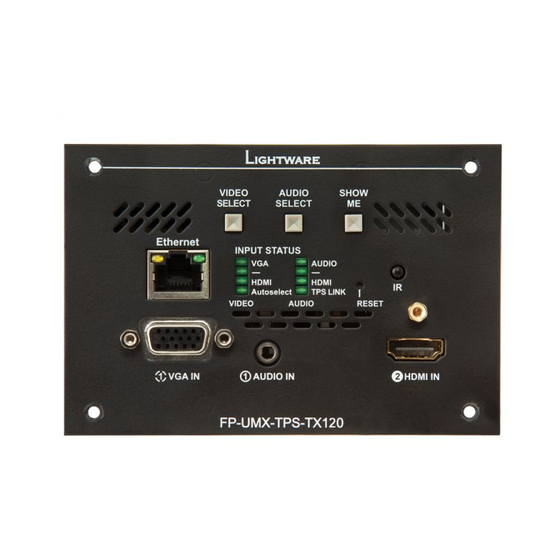
Page 19: Front View - Fp-Umx-Tps-Tx100 Series
Ethernet Locking RJ-45 connector for configuring the device using Lightware Device Controller (LDC), or updating it using Lightware Device Updater (LDU). Any third-party control system can use this port to control the device. VGA input D-SUB connector for analog video signal. -
Page 20: Rear View - Fp-Umx-Tps-Tx100 Series
2. Product Overview UMX-TPS-TX100 series – User's Manual 2.5.1. Rear View - FP-UMX-TPS-TX100 series 2.6. Front Panel LEDs INFO: The operation of the status LEDs of WP-UMX-TPS-TX100 series and FP-UMX-TPS-TX100 series models are the same. ATTENTION! When Dark mode is enabled, no LEDs are on, even though the device is fully functional. #status VIDEO input LEDs Video source is not selected. -
Page 21: Rear Panel Leds
2. Product Overview UMX-TPS-TX100 series – User's Manual 2.7. Rear Panel LEDs Firmware Version Indication After being powered on, the transmitter lights up all LEDs, then displays its firmware version using three LIVE LED LEDs on the front panel: the upper three in the left column. The top LED means the first number of the firmware version –... -
Page 22: Front Panel Buttons
Analog audio Embedded digital audio 2.8.1. Video Select Button SELECT UMX-TPS-TX120: Desired video input can be selected by the Video Select button from the front panel. The selection order of the inputs depends on the model as follows: Analog audio Embedded digital audio... -
Page 23: Special Functions
This feature is available only from FW package v1.5.0b4. 2.9.6. Entering Firmware Update Mode This feature is to help finding the desired device in the Device discovery window of Lightware Device ATTENTION! This function is applicable only in special cases when the device is to be updated by the Controller software. -
Page 24: Installation
3. Installation UMX-TPS-TX100 series – User's Manual Installation The chapter is about the installation of the device and connecting to other appliances, presenting also the mounting options and further assembly steps ç Mounting Options - Standalone Transmitters ç... -
Page 25: Mounting Options - Standalone Transmitters
3.1. Mounting Options - Standalone Transmitters 3.1.2. Under-desk Double Mounting Kit To mount the transmitter Lightware supplies optional accessories for different usage. There are two kinds of mounting kits with similar fixing method. The device has two mounting holes with inner thread on the bottom side;... -
Page 26: Mounting Options - Floor Plates
UMX-TPS-TX100 series – User's Manual 3.2. Mounting Options - Floor Plates Dimensions of the Bracket The following drawing and table represents the dimensions of the Lightware brackets assembled with the 3.2.1. MKM Mounting Option transmitter unit. The values are in mm. Floor Box Compatibility Table The FP-UMX-TPS MKM kit can be ordered separately, please contact sales@lightware.com. - Page 27 3. Installation UMX-TPS-TX100 series – User's Manual Step 5. Insert the bracket into the frame. Step 7. Fasten the fixing screws to fix the device into the floor box frame. Step 8. Place the transmitter to the bracket. Step 6.
-
Page 28: Mks Mounting Option
Step 1. Place the MKS bracket to the floor box so that the screw holes are able to fit. Fasten the bracket with Floor Box Compatibility Table both supplied DIN 7981 3,5x19 PZ2 self tapping screws. The FP-UMX-TPS MKS kit can be ordered separately, please contact sales@lightware.com. Compatible Service Outlet Boxes Compatible Lightware mounting bracket kit: FP-UMX-TPS MKS Kit... -
Page 29: Ges Mounting Option
3. Installation UMX-TPS-TX100 series – User's Manual 3.2.3. GES Mounting Option Compatible Service Outlets (Rectangular) Floor Box Compatibility Tables Compatible Lightware mounting bracket: FP-UMX-TPS GES4 Kit Compatible Service Outlets (Rectangular) Product family Type Part number Sample picture Compatible Service Outlets (Rectangular) - Page 30 3. Installation UMX-TPS-TX100 series – User's Manual Compatible Device Installation Units (Floor Boxes) Compatible Service Outlets (Rectangular) Compatible Lightware mounting bracket: FP-UMX-TPS GES9 Kit Compatible Lightware mounting bracket: FP-UMX-TPS GES4 Kit Product family Type Part number Sample picture...
- Page 31 The FP-UMX-TPS GES4 / GES9 kits can be ordered separately, please contact sales@lightware.com. Dimensions of the Brackets The following drawing and table represents the dimensions of the Lightware brackets assembled with the transmitter unit. The two types of GES bracket pairs have different dimensions. The values are in mm.
-
Page 32: Mounting Options - Wall Plates
The transmitter can be easily mounted into an industrial standard switch/outlet box (B225R): Switch / Outlet Box Compatibility Table INFO: The switch/outlet box is not supplied with the mounting kit but it can be purchased separately. Compatible Lightware Devices: Please contact sales@lightware.com for the details. -
Page 33: Electrical Connections
3. Installation UMX-TPS-TX100 series – User's Manual 3.4. Electrical Connections 3.4.5. DisplayPort Connector UMX-TPS-TX140, UMX-TPS-TX140-Plus, UMX-TPS-TX140K, WP-UMX-TPS-TX130-US, and 3.4.1. Locking 12V DC Connection WP-UMX-TPS-TX130-Plus-US models provide standard 20-pole DisplayPort connector for input. Always use high quality DP cable for connecting DisplayPort devices. 3.4.6. DVI-I Connector UMX-TPS-TX130, UMX-TPS-TX140, UMX-TPS-TX140K and UMX-TPS-TX140-Plus transmitters provide a standard 29-pole DVI-I connector for input where digital and analog pins are connected internally. -
Page 34: Analog Stereo Audio (Jack)
You can find more information about audio functions in the Audio Interface section. Lightware recommends the termination of LAN cables on the basis of TIA/EIA T 568 A or TIA/EIA T 568 B standards. 3.4.8. Analog Stereo Audio (Phoenix) 5-pole Phoenix connector is used for balanced analog audio input in the UMX-TPS- TX140 and UMX-TPS-TX140-Plus transmitters. -
Page 35: Connector
3. Installation UMX-TPS-TX100 series – User's Manual 3.4.10. RS-232 Connector 3.4.13. GPIO - General Purpose Input/Output Ports The extender contains a 3-pole Phoenix connector which is used for RS-232 serial connection. DIFFERENCE: Only the UMX-TPS-TX130, UMX-TPS-TX140 and UMX-TPS-TX140-Plus models contain GPIO port. -
Page 36: Connecting Steps
3. Installation UMX-TPS-TX100 series – User's Manual 3.5. Connecting Steps 3.5.2. UMX-TPS-TX100 series 3.5.1. FP/WP-UMX-TPS-TX100 series CATx Connect the transmitter and a compatible receiver or the matrix input board by a CATx cable via the TPS connectors. DVI DP Connect the transmitter and the sources using the inputs and VGA / DVI-I / HDMI / DisplayPort HDMI cables. -
Page 37: Powering Options
3. Installation UMX-TPS-TX100 series – User's Manual 3.6. Powering Options Using local PSU - connect the power adaptor to the DC input on the transmitter first, then to the AC power socket. Using PoE with connecting a transmitter: connect the TPS OUT (PoE) port of the transmitter to the TPS+PoE port of the TPS-PI-1P1 power injector by a CATx cable, and connect the TPS input port of the compatible receiver to the TPS port of the TPS-PI-1P1 by a CATx cable. -
Page 38: Device Concept
4. Device Concept UMX-TPS-TX100 series – User's Manual D evice Concept The following chapter describes the features of the device with a few real-life examples. ç TPS Extender Concept ç TPS Interface ç Port Diagrams ç Video Interface ç... -
Page 39: Tps Extender Concept
4. Device Concept UMX-TPS-TX100 series – User's Manual 4.1. TPS Extender Concept 4.2. TPS Interface The UMX-TPS-TX100 series transmitters and wall plates are universal audio/video extenders with analog/ The device is built with TPS (Twisted Pair Single) interface which are using HDBaseT technology. -
Page 40: Port Diagrams
The following figure describes the port diagram of the UMX-TPS-TX140 transmitter. The principle of the WP-UMX-TPS-TX120-US series ▪ operation is the same for the following models. ▪ WP-UMX-TPS-TX130-US series ▪ UMX-TPS-TX120, -TX130, -TX140 ▪ WP-UMX-TPS-TX130-Plus-US series ▪ UMX-TPS-TX140-Plus FP-UMX-TPS-TX120 ▪... -
Page 41: Video Interface
VGA IN Port with Port with priority priority 1 has a 1 is selected valid signal? Priorities can be set in Lightware Device Controller software, see related settings in the TPS Video Output and the TPS Audio Output sections. Port with... -
Page 42: Audio Interface
4. Device Concept UMX-TPS-TX100 series – User's Manual 4.6. Audio Interface 4.6.2. Audio Options - Example The Concept 4.6.1. Audio Input Modes The device can receive embedded digital audio signal on the HDMI, DisplayPort, and DVI-D input ports and analog audio signal on the Jack and the Phoenix input ports. -
Page 43: Serial Interface
4. Device Concept UMX-TPS-TX100 series – User's Manual 4.7. Serial Interface Control Mode The incoming data from the given port is processed and interpreted by the CPU. The mode allows to control 4.7.1. Technical Background the transmitter directly. LW2 or LW3 protocol commands are accepted – depending on the current port Serial data communication can be established via the local RS-232 port (Phoenix connector) or via the TPS setting. -
Page 44: Recognizer
First, configure the recognizer for the serial communication, after that, set the events in the Event Manager (for over Ethernet (Wake-on-LAN) section. more details see the Event Manager section). The RS-232 recognizer settings has to be done with Lightware Device Controller Software (see the Message Recognizer section) or with LW3 protocol commands (see the INFO: Please make sure the feature is enabled in the target PC and it is powered (but switched off). -
Page 45: Tcprecognizer
This feature allows the LW device to be controlled over HTTP. In this case, a batch of commands is sent ▪ Cleartext login over HTTP to the Lightware device for processing. Save the LW3 commands into a file, post it to the <IP_address>/protocol.lw3 file and the commands are processed immediately. #http ▪... -
Page 46: Ir Interface
4. Device Concept UMX-TPS-TX100 series – User's Manual 4.11. IR Interface IR Signal Transmission - Example 1 ATTENTION! For the complete usage attach an IR emitter unit to the IR OUT and an IR detector unit to the IR IN connectors. -
Page 47: Advanced Ir Functionality
The Event Manager feature means that the device can sense changes on its ports and is able to react independently based on needs of the application. according to the pre-defined settings. Lightware Device Controller contains a user-friendly software tool and 4.12.2. GPIO Options - Example allows to create Events by defining a Condition and an Action. -
Page 48: Usb Interface (Kvm Function)
A brand new area is opened by implementing the variables. You can create custom variables in number transmitted packets are unknown to the Lightware infrastructure so the data is not modified by any means or text format which can be used in the Event Manager. The variables can have the following properties/ during transmission. -
Page 49: Consumer Electronics Control (Cec) Feature
User has more possibilities to control the device besides the front panel buttons. The following list contains the software control modes: Lightware Device Controller (LDC) - you can connect to the device via our control software using Ethernet ▪ or RS-232 interface and control or configure the device as you wish. For the details see the... -
Page 50: Software Control - Lightware Device Controller
S oftware Control - Lightware Device Controller The device can be controlled by a computer through the Ethernet and RS-232 ports using Lightware Device Controller (LDC). The software can be installed on a Windows PC or macOS. The application and the User’s manual can be downloaded from www.lightware.com. -
Page 51: Install And Update
(100%). The Device Discovery window appears automatically and the program checks the available updates on Lightware’s website and opens the update window if the LDC found updates. Format: LightwareDeviceController -z <magnifying_value> The current and the update version number can be seen at the top of the window and they are shown in this Example: LightwareDeviceController -z 1.2... -
Page 52: Connecting To A Device (Device Discovery Window)
Step 1. Connect the device to a computer via USB, RS-232 or Ethernet. as you can expand the list of Favorite devices with any Lightware device that is connected via Ethernet by any Step 2. Run the controller software; device discovery window appears automatically. There are three tabs for of the following ways: the different type of interfaces: Ethernet, Serial, and USB. -
Page 53: Serial Tab
5. Software Control - Lightware Device Controller UMX-TPS-TX100 series – User's Manual 5.3.4. Further Tools Highlighting the Device DIFFERENCE: This feature is available only from FW package v1.5.0b4. The Tools menu contains the following options: The opposite feature is also available to help finding the desired device. Press the Show Me button for 5 Log Viewer: The tool can be used for reviewing log files which have been saved previously. -
Page 54: Crosspoint Menu
5. Software Control - Lightware Device Controller UMX-TPS-TX100 series – User's Manual 5.4. Crosspoint Menu Port Tiles #status The colors of the port tiles and the displayed icons represent different states and information: Port name Port icon... -
Page 55: Port Properties Windows
5. Software Control - Lightware Device Controller UMX-TPS-TX100 series – User's Manual 5.5. Port Properties Windows Available settings: #mute #unmute #lock #unlock #testpattern ▪ Mute/unmute the port; #nosyncscreen Clicking on the port tile opens the Port properties window. This section shows the available settings and Lock/unlock the port;... -
Page 56: Digital Video Inputs
5. Software Control - Lightware Device Controller UMX-TPS-TX100 series – User's Manual 5.5.2. Digital Video Inputs 5.5.3. TPS Video Output Clicking on the HDMI, DisplayPort, or DVI-D input port icon results opening the Port properties window. The Click on the output port to display its properties. The most important information and settings are available most important information and settings are available from the panel. -
Page 57: Analog Audio Inputs
5. Software Control - Lightware Device Controller UMX-TPS-TX100 series – User's Manual 5.5.4. Analog Audio Inputs Available settings: #mute #unmute #lock #unlock #testpattern ▪ Mute/unmute the port; #nosyncscreen Lock/unlock the port; ▪ Autoselect settings: enable / disable, mode, and priorities. (See more details about Autoselect feature ▪... -
Page 58: Digital Audio Inputs
5. Software Control - Lightware Device Controller UMX-TPS-TX100 series – User's Manual 5.5.5. Digital Audio Inputs 5.5.6. TPS Audio Output Certain parameters of the digital audio output signal can be set as follows: Port properties window of HDMI audio input Certain parameters of the embedded audio input signal can be set as follows: ▪... -
Page 59: The Cec Tool
5. Software Control - Lightware Device Controller UMX-TPS-TX100 series – User's Manual 5.6. The CEC Tool Drop-down This list contains the basic CEC commands, most of them are displayed on the graphical command interface, too (on the left side). Click on the Send button to execute sending the command. -
Page 60: Diagnostic Tools
5. Software Control - Lightware Device Controller UMX-TPS-TX100 series – User's Manual 5.7. Diagnostic Tools Table and Chart Views #cablediagnostics Cable diagnostics can be displayed in advanced modes as well. Two ways are available: table view and chart 5.7.1. Cable Diagnostics... -
Page 61: Test Pattern
5. Software Control - Lightware Device Controller UMX-TPS-TX100 series – User's Manual 5.7.2. Test Pattern Test Pattern Configuration on Video Input Ports The port generates an image which can be displayed when there is no incoming signal on the port. Each port can have individual settings which can be set by clicking on the Configure button. -
Page 62: Frame Detector
Frame detector button. Frame detector window Lightware’s Frame Detector function works like a signal analyzer and makes possible to determine the exact EDID menu video format that is present on the port, thus helps to identify many problems. E.g. actual timing parameters Control Buttons may differ from the expected and this may cause some displays to drop the picture. -
Page 63: Edid Operations
5. Software Control - Lightware Device Controller UMX-TPS-TX100 series – User's Manual 5.8.1. EDID Operations 5.8.2. EDID Summary Window Select an EDID from Source panel and press Info button to display EDID summary. Changing Emulated EDID #edid Step 1. Choose the desired EDID list on the source panel and select an EDID. -
Page 64: Editing An Edid
All descriptors can be edited, and saved in an EDID file, or uploaded to the User EDID Editor please visit our website (www.lightware.com) and download the EDID Editor Application note. memory. For more details about EDID Editor please visit our website (www.lightware.com) and download EDID Editor Application note. #edid... -
Page 65: Control Menu
5. Software Control - Lightware Device Controller UMX-TPS-TX100 series – User's Manual 5.9. Control Menu 5.9.2. Message Recognizer DIFFERENCE: This feature available 5.9.1. RS-232 Tab UMX-TPS-TX140-Plus, UMX-TPS-TX140K WP-UMX-TPS-TX130-US models. The device can analyze and store the received serial data. -
Page 66: Gpio Tab
5. Software Control - Lightware Device Controller UMX-TPS-TX100 series – User's Manual 5.9.3. GPIO Tab Configuration Example for the Message Recognizer The detailed description below shows how to configure the message recognizer in RS-232 Recognizer Example. When the UMX-TPS-TX140-Plus has an active video signal, the transmitter login the VC codec automatically. -
Page 67: Ethernet
ATTENTION! This feature means posting or putting HTTP messages from the Lightware device to another device. Encrypted transmission (HTTPS) is not supported. The HTTP Clients tab allows sending HTTP post and put messages to the desired server IP:port no. Control commands can be set to the target device, but it is not suitable for processing the response (e.g. - Page 68 Encrypted transmission (HTTPS) is not supported. In this case, a batch of commands can be sent over HTTP to the Lightware device for processing. Post the commands to the <IP_address>/protocol.lw3 address and the commands are processed immediately and sequentially.
-
Page 69: Infra Tab
5. Software Control - Lightware Device Controller UMX-TPS-TX100 series – User's Manual 5.9.5. Infra Tab Description Function ATTENTION! The device has no built-in Infrared receiver and transmitter. For the complete usage attach Code number. an IR emitter unit to the IR OUT and an IR detector unit to the IR IN connectors. - Page 70 5. Software Control - Lightware Device Controller UMX-TPS-TX100 series – User's Manual Ports Section of the UMX-TPS-TX100 Series Devices Ports Section of the UMX-TPS-TX140-Plus UMX-TPS-TX140K and WP-UMX-TPS-TX130-US Models User can set the name and command injection port to each sources and destinations. For more details...
-
Page 71: Macros
5. Software Control - Lightware Device Controller UMX-TPS-TX100 series – User's Manual 5.9.6. Macros DIFFERENCE: This feature is available only in UMX-TPS-TX140K and TX140-Plus models from FW package v1.5.0b4. DEFINITION: Macro is a batch of pre-defined commands stored in the device. -
Page 72: Variables
5. Software Control - Lightware Device Controller UMX-TPS-TX100 series – User's Manual 5.9.7. Variables Value Section You can set the value of the variable by the field. The type of the variable is determined automatically based DIFFERENCE: This feature is available only in UMX-TPS-TX140K and TX140-Plus models from FW on its value (numeric/string). - Page 73 5. Software Control - Lightware Device Controller UMX-TPS-TX100 series – User's Manual Scan and Store This tool can be used to get the value (or a part) of an LW3 property. The defined path will be checked according to the pattern and the result will be saved into the variable (number or string type).
-
Page 74: Event Manager
5. Software Control - Lightware Device Controller UMX-TPS-TX100 series – User's Manual 5.10. Event Manager 5.10.1. The Event Editor Press the Edit button in the desired Event line to open the Event editor window. The feature means that the device can sense changes on its ports and able to react according to the pre-defined settings. -
Page 75: Create Or Modify An Event
5. Software Control - Lightware Device Controller UMX-TPS-TX100 series – User's Manual 5.10.2. Create or Modify an Event The Link Tool The new interface allows creating more actions for the Wizard Mode same condition. In that case, a condition can trigger The wizard mode lists the most common conditions more actions. -
Page 76: Special Tools And Accessories
5. Software Control - Lightware Device Controller UMX-TPS-TX100 series – User's Manual Linking a Macro (Action) Delay the Action no delay Condition = true Perform the action DIFFERENCE: This feature is available In most cases the Action is... -
Page 77: Clear One Or More Event(S)
5. Software Control - Lightware Device Controller UMX-TPS-TX100 series – User's Manual Condition Triggering CONDITION ACTION DIFFERENCE: This feature available only in UMX-TPS-TX140K and TX140-Plus models from FW package v1.5.0b4. This improvement works as if a... -
Page 78: Settings Menu
5. Software Control - Lightware Device Controller UMX-TPS-TX100 series – User's Manual 5.11. Settings Menu Step 2. Set the action. If the condition is fulfilled, the following action needs to be launched: the receiver sends a command to the 5.11.1. Status... -
Page 79: Network
▪ Settings) section. There are TCP/IP ports in Lightware devices which are not protected by the login, so you disabled, it means that pushing the button will not perform the original function. This makes the can disable them if necessary. For example, due to the working method of the LW2 communication, the... -
Page 80: Backup
5. Software Control - Lightware Device Controller UMX-TPS-TX100 series – User's Manual 5.11.4. Backup Further functions ▪ Download system log - saving the file of the device. Details about this function can be found in the Configuration Cloning (Backup Tab) section. -
Page 81: Configuration Cloning (Backup Tab)
Installing multiple devices with the same customized configuration settings can be done in a few easy steps: Configuration cloning of Lightware LW3 devices is a simple method that eliminates the need to repeatedly configure certain devices to have identical (non-factory) settings. If the devices are installed in the same Step 1. -
Page 82: Upload The Settings To A Device (Restore)
5. Software Control - Lightware Device Controller UMX-TPS-TX100 series – User's Manual 5.12.3. Upload the Settings to a Device (Restore) WARNING! Please note that the settings will be permanently overwritten with the restored parameters in the device. Withdrawal is not possible. -
Page 83: The Built-In Miniweb
5. Software Control - Lightware Device Controller UMX-TPS-TX100 series – User's Manual 5.13. The Built-In Miniweb 5.13.1. Opening the Miniweb The Miniweb is available by: DEFINITION: The miniweb is a dedicated location in the memory where an HTML file can be uploaded to. -
Page 84: Miniweb Customization
5. Software Control - Lightware Device Controller UMX-TPS-TX100 series – User's Manual The Default Status Page Customized HTML If there is no control page uploaded, the default status page will be displayed (which is also available by The default control page can be replaced in the LDC;... -
Page 85: Advanced View Window
5. Software Control - Lightware Device Controller UMX-TPS-TX100 series – User's Manual 5.14. Advanced View Window LW3 protocol help Pushing the button results a help window opening which describes the most important information about LW3 protocol commands in HTML format. -
Page 86: Lw2 Programmer's Reference
L W2 Programmer' s Reference The device can be controlled through a reduced command set of LW2 protocol commands to ensure the compatibility with other Lightware products. The supported LW2 commands are described in this chapter. ç LW2 Protocol Description ç... -
Page 87: Lw2 Protocol Description
UMX-TPS-TX100 series – User's Manual 6.1. LW2 Protocol Description 6.2. Instructions for the Terminal Application Usage The protocol description hereinafter stands for Lightware protocol. The commands can be sent to the device Terminal Application in RAW format via the TCP/IP port no. 10001. -
Page 88: General Lw2 Commands
6. LW2 Programmer's Reference UMX-TPS-TX100 series – User's Manual 6.3. General LW2 Commands 6.3.4. Query Control Protocol This command queries the active protocol of the currently used control interface. 6.3.1. List of All Available LW2 Commands Command and Response #protocol Command and Response ȩ... -
Page 89: View Serial Number
6. LW2 Programmer's Reference UMX-TPS-TX100 series – User's Manual 6.3.8. View Serial Number 6.3.11. Query Health Status The device responds its 8-digit serial number. Internal voltages and measured temperature values are shown. Command and Response #serialnumber Command and Response #status ȩ... -
Page 90: Av Port Settings
6. LW2 Programmer's Reference UMX-TPS-TX100 series – User's Manual 6.4. AV Port Settings 6.4.2. Mute Output Mute the <out> output. The output signal is turned off. 6.4.1. Switch an Input to the Outputs Command and Response #mute #lock #unmute #unlock Switching an input <in>... -
Page 91: Unlock Output
6. LW2 Programmer's Reference UMX-TPS-TX100 series – User's Manual 6.4.5. Unlock Output 6.4.7. View Crosspoint Size Unlocking an output port. The connection on output can be changed. Shows the physical crosspoint size. Command and Response Command and Response ȩ... -
Page 92: Change The Audio Autoselect Mode
6. LW2 Programmer's Reference UMX-TPS-TX100 series – User's Manual 6.4.9. Change the Audio Autoselect Mode 6.4.11. Change the Audio Input Priorities The autoselect mode of the audio output can be changed. The settings of audio input priority can be changed as follows. Command and Response Command and Response ȩ... -
Page 93: Network Configuration
6. LW2 Programmer's Reference UMX-TPS-TX100 series – User's Manual 6.5. Network Configuration 6.5.3. Set the Subnet Mask Subnet mask can be set as follows. 6.5.1. Query the Current IP Status Command and Response The IP address settings can be queried as follows. #dhcp #ipaddress #network ȩ... -
Page 94: Enable/Disable The Ethernet Port
6. LW2 Programmer's Reference UMX-TPS-TX100 series – User's Manual 6.5.6. Enable/disable the Ethernet Port 6.6.2. RS-232 Parameters Settings Command and Response The parameters of local RS -232 port can be set as follows. ȩ {ETH_ENABLE=<switch>} Command and Response Ȩ... -
Page 95: Control Protocol Port Setting
6. LW2 Programmer's Reference UMX-TPS-TX100 series – User's Manual 6.6.3. RS-232 Control Protocol Port Setting 6.6.5. Serial Port Protocol Setting (Link port) The control protocol of local RS -232 port can be set as follows. This command sets the communication protocol of the link RS-232 port (TPS port). Command and Response #protocol Command and Response... -
Page 96: Lw2 Commands - Quick Summary
6. LW2 Programmer's Reference UMX-TPS-TX100 series – User's Manual 6.8. LW2 Commands – Quick Summary General LW2 Commands List of All Available LW2 Commands Unmute Output ȩ {lcmd} ȩ {+<out>•<layer>} View Product Type Lock Output ȩ {i} ȩ... - Page 97 6. LW2 Programmer's Reference UMX-TPS-TX100 series – User's Manual RS-232 Settings RS-232 Mode Setting ȩ {RS232=<mode>} RS-232 Parameters Settings ȩ {RS232_LOCAL_FORMAT=<BaudRate>;<DataBit>;<Parity>;<StopBit>} RS-232 Control Protocol Port Setting ȩ {RS232_LOCAL_PROT=<protocol>} Serial Port Format Setting (Link port) ȩ {RS232_LINK_FORMAT=<baud_rate>;<data_bit>;<parity>;<stop_bit>} Serial Port Protocol Setting (Link port) ȩ...
-
Page 98: Lw3 Programmers' Reference
7. LW3 Programmers’ Reference UMX-TPS-TX100 series – User's Manual L W3 Programmers’ Reference The device can be controlled through Lightware 3 (LW3) protocol commands to ensure the compatibility with other Lightware products. The supported LW3 commands are described in this chapter. ç Overview ç... -
Page 99: Overview
‘nodes’, ‘properties’ and ‘methods’. The VIDEO Advanced View of the Lightware Device Controller software is the perfect tool for browsing and learning how XP the LW3 protocol can be used in practice. -
Page 100: Legend For The Control Commands
7. LW3 Programmers’ Reference UMX-TPS-TX100 series – User's Manual 7.3.3. Legend for the Control Commands SET command The SET command can be used to modify the value of a property. Use the dot character (.) when addressing Command and Response –... -
Page 101: Escaping
7. LW3 Programmers’ Reference UMX-TPS-TX100 series – User's Manual 7.3.7. Escaping Subscribe to a Node Unsubscribe from a Node ç OPEN /MEDIA/VIDEO ç CLOSE /MEDIA/VIDEO DEFINITION: An escape sequence is a sequence of characters that does not represent itself when used inside a character or string literal, but is translated into another character or a sequence of characters. -
Page 102: System Commands
7. LW3 Programmers’ Reference UMX-TPS-TX100 series – User's Manual 7.4. System Commands 7.4.4. Query the Firmware Version 7.4.1. Query the Product Name Command and Response #firmwareversion ç GET·/SYS/MB.FirmwareVersion The name of the product is a read-only parameter and cannot be modified. pr·/SYS/MB.FirmwareVersion=<firmware_version>... -
Page 103: Lock The Front Panel Buttons
7. LW3 Programmers’ Reference UMX-TPS-TX100 series – User's Manual 7.4.7. Lock the Front Panel Buttons 7.4.9. Dark Mode This command turns LEDs off the on the transmitter. #darkmode Command and Response #frontpanel #controllock #button ç SET /MANAGEMENT/UI.ControlLock=<lock_status> Command and Response æ... -
Page 104: Running A Macro
7. LW3 Programmers’ Reference UMX-TPS-TX100 series – User's Manual 7.4.11. Running a Macro 7.5.2. Login the Device DIFFERENCE: This feature is available only in UMX-TPS-TX140K and TX140-Plus models from FW Command and Response package v1.5.0b4. ç CALL·/LOGIN:login(<password>) DEFINITION: Macro is a batch of pre-defined commands stored in the device. -
Page 105: Video Port Settings
7. LW3 Programmers’ Reference UMX-TPS-TX100 series – User's Manual 7.6. Video Port Settings The Most Common Received Port Status Responses INFO: Video port numbering can be found in the Port Numbering section. #status 7.6.1. Query the Status of Source Ports T00AA Unlocked, No embedded... -
Page 106: Query The Status Of Destination Port
7. LW3 Programmers’ Reference UMX-TPS-TX100 series – User's Manual 7.6.2. Query the Status of Destination Port 7.6.5. Switching Video Input Command and Response #status Command and Response #crosspoint #switch ç GET·/MEDIA/VIDEO/XP.DestinationPortStatus ç CALL·/MEDIA/VIDEO/XP:switch(<in>:<out>) pr·/MEDIA/VIDEO/XP.DestinationPortStatus=<out1_state>;<out2_state>;<…>;<out#_state> æ æ mO·/MEDIA/VIDEO/XP:switch Parameters Example <out#_state>... -
Page 107: Query The Video Autoselect Settings
7. LW3 Programmers’ Reference UMX-TPS-TX100 series – User's Manual 7.6.7. Query the Video Autoselect Settings 7.6.9. Query the Input Port Priority Command and Response Command and Response ç GET·/MEDIA/VIDEO/XP.PortPriorityList ç GET·/MEDIA/VIDEO/XP.DestinationPortAutoselect æ pr·/MEDIA/VIDEO/XP.PortPrioirtyList= <out1_list>;<out2_list>;<…>;<out#_list> pr·/MEDIA/VIDEO/XP.DestinationPortAutoselect=<out1_set>;<out2_set>;<…>;<out#_set> æ The response shows the priority of each output one after another. The priority number can be from 0 to 31; Parameters 0 is the highest- and 30 is the lowest priority. -
Page 108: Mute An Input Port
7. LW3 Programmers’ Reference UMX-TPS-TX100 series – User's Manual 7.6.11. Mute an Input Port 7.6.15. Mute Output Command and Response #mute #unmute Command and Response ç CALL·/MEDIA/VIDEO/XP:muteSource(<in>) ç CALL·/MEDIA/VIDEO/XP:muteDestination(<out>) æ mO·/MEDIA/VIDEO/XP:muteSource æ mO·/MEDIA/VIDEO/XP:muteDestination Example Example ç CALL /MEDIA/VIDEO/XP:muteSource(I1) ç... -
Page 109: Hdcp Setting (Input Port)
7. LW3 Programmers’ Reference UMX-TPS-TX100 series – User's Manual 7.6.19. HDCP Setting (Input Port) 7.6.21. Test Pattern Color HDCP capability can be enabled/disabled on the input ports, thus, non-encrypted content can be seen on a Command and Response non-HDCP compliant display. -
Page 110: Hdcp Setting (Output Port)
7. LW3 Programmers’ Reference UMX-TPS-TX100 series – User's Manual 7.6.23. HDCP Setting (Output Port) 7.6.25. Color Space Setting (Output Port) HDCP capability can be set to Auto/Always on the output ports, thus, non-encrypted content can be Command and Response #colorspace transmitted to a non-HDCP compliant display. -
Page 111: Audio Port Settings
7. LW3 Programmers’ Reference UMX-TPS-TX100 series – User's Manual 7.7. Audio Port Settings Example and Explanation (for input 2, M000B): INFO: Audio port numbering can be found in the Port Numbering section. 7.7.1. Query the Status of Source Ports Unlocked, Muted Reserved... -
Page 112: Query The Status Of Destination Port
7. LW3 Programmers’ Reference UMX-TPS-TX100 series – User's Manual 7.7.2. Query the Status of Destination Port 7.7.5. Query the Audio Autoselect Settings Command and Response Command and Response ç GET·/MEDIA/AUDIO/XP.DestinationPortStatus ç GET·/MEDIA/AUDIO/XP.DestinationPortAutoselect pr·/MEDIA/AUDIO/XP.DestinationPortStatus=<out1_state> pr·/MEDIA/AUDIO/XP.DestinationPortAutoselect=<out_set> æ æ The response contains 5 ASCII characters for each port. The first character indicates the mute/lock state, The response shows the settings of each output one by one. -
Page 113: Change The Autoselect Mode
7. LW3 Programmers’ Reference UMX-TPS-TX100 series – User's Manual 7.7.6. Change the Autoselect Mode 7.7.7. Query the Input Port Priority Command and Response #audio Command and Response ç CALL·/MEDIA/AUDIO/XP:setDestinationPortAutoselect(<out>:<out_set>) ç GET·/MEDIA/AUDIO/XP.PortPriorityList æ mO·/MEDIA/AUDIO/XP.setDestinationPortAutoselect æ pr·/MEDIA/AUDIO/XP.PortPrioirtyList= <out1_list>;<out2_list>;<…>;<out#_list> The response shows the priority of each output one after another. The priority number can be from 0 to 31; Parameters 0 is the highest- and 30 is the lowest priority. -
Page 114: Mute An Audio Input
7. LW3 Programmers’ Reference UMX-TPS-TX100 series – User's Manual 7.7.9. Mute an Audio Input 7.7.13. Mute Audio Output Command and Response #audio #mute Command and Response #audio #mute ç CALL·/MEDIA/AUDIO/XP:muteSource(<in>) ç CALL·/MEDIA/AUDIO/XP:muteDestination(<out>) æ mO·/MEDIA/AUDIO/XP:muteSource æ mO·/MEDIA/AUDIO/XP:muteDestination Example Example ç... -
Page 115: Analog Audio Input Level Settings
7. LW3 Programmers’ Reference UMX-TPS-TX100 series – User's Manual 7.8. Analog Audio Input Level Settings 7.8.1. Volume Command and Response #analogaudio #volume SET·/MEDIA/AUDIO/<in>.Volume=<level> ç pw·/MEDIA/AUDIO/<in>.Volume=<level> æ Parameters <level> Sets the input volume (attenuation) between -95.625 dB and 0 dB in step of -0.375 dB. The value is rounded up if necessary to match with the step value. -
Page 116: Event Manager Basics
7. LW3 Programmers’ Reference UMX-TPS-TX100 series – User's Manual 7.9. Event Manager Basics 7.9.2. Setting a Condition by Linking Another Condition Command and Response The graphical interface of the Event Manager can be found in the LDC which allows creating any kind of Events. -
Page 117: Setting An Action By Specifying A Direct Path
7. LW3 Programmers’ Reference UMX-TPS-TX100 series – User's Manual 7.9.4. Setting an Action by Specifying a Direct Path 7.10. Event Manager Tool Kit Command and Response 7.10.1. Setting the Delay SET·/EVENTS/E<loc>.Action=<expression> ç In most cases, the Action is performed immediately after the Condition is detected. But sometimes a delay pw·/EVENTS/E<loc>.Action=<expression>... -
Page 118: Setting The Name Of The Event
7. LW3 Programmers’ Reference UMX-TPS-TX100 series – User's Manual 7.10.3. Enable the Event Example 1 (simple delay) ç SET /EVENTS/E1.ConditionTimeout=10 Command and Response æ pw /EVENTS/E1.ConditionTimeout=10 SET·/EVENTS/E<loc>.Enabled=<true/false> ç If the Condition is detected (the ConditionDetect property becomes true), the ConditionTimeoutPending property pw·/EVENTS/E<loc>.Enabled=<true/false>... -
Page 119: Querying The Condition Trigger Counter
7. LW3 Programmers’ Reference UMX-TPS-TX100 series – User's Manual 7.10.6. Querying the Condition Trigger Counter 7.11. Variable-Management DIFFERENCE: This feature is available only in UMX-TPS-TX140K and TX140-Plus models from FW DIFFERENCE: This feature is available only in UMX-TPS-TX140K and TX140-Plus models from FW package v1.5.0b4. -
Page 120: Addition And Subtraction (Cycle Method)
7. LW3 Programmers’ Reference UMX-TPS-TX100 series – User's Manual 7.11.3. Addition and Subtraction (Cycle Method) Examples Change messages (CHG) can be seen after each response for the better understanding, which is not the part The value of a numeric variable can be increased by adding a positive value or it can be decreased by adding of the command, but it can be set as described in the Subscription section. -
Page 121: Value Change With Intervals (Case)
7. LW3 Programmers’ Reference UMX-TPS-TX100 series – User's Manual 7.11.4. Value Change with Intervals (Case) 7.11.5. Scan and Store This command can be used to change the value of a variable if it fits in any of the defined intervals. This command can be used to get the value (or a part of the value) of an LW3 property. -
Page 122: Reformatting A Value
SET·/MANAGEMENT/NETWORK.DhcpEnabled=<dhcp_status> ç /MEDIA/AUDIO/XP.SourcePortStatus T000A;T000B;T000F %*6c%5c T000B pw·/MANAGEMENT/NETWORK.DhcpEnabled=<dhcp_status> æ /MANAGEMENT/NETWORK.HostName lightware-00005031 lightware-%[0-9] 00005031 Parameters 7.11.6. Reformatting a Value If the <dhcp_status> parameter is true, the current IP address setting is DHCP, if the parameter is false the current IP address is static. -
Page 123: Change The Subnet Mask (Static)
New MAC address is saved into the 4th property with name 'Tech', which may query/set parameters from/in the Lightware device. The FilterEnable property is set to true, thus, the filter is enabled. Applied firmware packages: (UMX-TPS): v1.5.0b4 | (WP-UMX-TPS): v1.4.0b8 | (FP-UMX-TPS): v1.4.0b8 | LDC software: v2.5.6b2... -
Page 124: Lw2 Control Port Blocking
7. LW3 Programmers’ Reference UMX-TPS-TX100 series – User's Manual 7.13.2. LW2 Control Port Blocking 7.13.5. Powering on a Computer over Ethernet (Wake-on-LAN) DIFFERENCE: This feature is available only in UMX-TPS-TX140K and TX140-Plus models from FW DIFFERENCE: This command is available only from FW package v1.5.0b4. package v1.5.0b4. -
Page 125: Ethernet Message Sending
7. LW3 Programmers’ Reference UMX-TPS-TX100 series – User's Manual 7.14. Ethernet Message Sending 7.14.3. Sending a TCP Binary Message (HEX-format) The command is for sending a binary message in Hexadecimal format. This method does not require escaping The device can be used for sending a message to a certain IP:port address. The three different commands the control and non-printable characters. -
Page 126: Sending A Udp Text (Ascii-Format)
This feature is available only in UMX-TPS-TX140K and TX140-Plus models from FW escaping or inserting control characters. package v1.5.0b4. Command and Response Http post and put messages can be sent from the Lightware device for more integration with third-party devices. #http ç CALL·/MEDIA/ETHERNET:udpText(<IP_address>:<port_no>=<text>) æ... -
Page 127: Setting The Message Header
ç SET /CTRL/HTTP/C1.Header=Host: 192.168.0.220\r\nContent-Type: text/xml\r\nAuthorization: Basic Preparation YWRtaW46TGlnaHR3YXJlMDE= Step 1. Set a TCP client in the Lightware device (three TCP clients can be run at the same time), set the æ pw /CTRL/HTTP/C1.Header=Host: 192.168.0.220\r\nContent-Type: text/xml\r\nAuthorization: Basic properties of the target TCP server. -
Page 128: Setting The Tcp/Ip Port Number Of The Tcp Server
7. LW3 Programmers’ Reference UMX-TPS-TX100 series – User's Manual 7.16.2. Setting the TCP/IP Port Number of the TCP Server 7.16.6. Setting the Timeout Command and Response When the set time is elapsed after the last received message and delimiter was not detected, the device saves the data into the Rx, RxHex, Hash properties. -
Page 129: Querying The Last Recognized Message (Hex)
7. LW3 Programmers’ Reference UMX-TPS-TX100 series – User's Manual 7.16.8. Querying the Last Recognized Message (Hex) 7.16.11. Querying the Last Recognized Active Message (Hex) The recognized message is stored as a hex message in the below property till the next recognized message Command and Response or until the clear() method is called. -
Page 130: Port Configuration
7. LW3 Programmers’ Reference UMX-TPS-TX100 series – User's Manual 7.17. RS-232 Port Configuration 7.17.2. BAUD Rate Setting INFO: Serial port numbering can be found in the Port Numbering section. Command and Response 7.17.1. Protocol Setting SET·/MEDIA/UART/<port>.Baudrate=<baudrate> ç pw·/MEDIA/UART/<port>.Baudrate=<baudrate> æ Command and Response #rs232 #rs-232 #serial #controlprotocol Parameters... -
Page 131: Stopbits Setting
7. LW3 Programmers’ Reference UMX-TPS-TX100 series – User's Manual 7.17.4. Stopbits Setting 7.17.6. RS-232 Operation Mode Command and Response Command and Response #rs232 #rs-232 #serial #commandinjection SET·/MEDIA/UART/<port>.StopBits=<stopbits> SET·/MEDIA/UART/<port>.Rs232Mode=<mode> ç ç pw·/MEDIA/UART/<port>.StopBits=<stopbits> pw·/MEDIA/UART/<port>.Rs232Mode=<mode> æ æ Parameters Parameters Identifier Parameter description Value Parameter value Identifier... -
Page 132: Message Sending
7. LW3 Programmers’ Reference UMX-TPS-TX100 series – User's Manual 7.18. RS-232 Message Sending 7.18.4. Using Hexadecimal Codes Hexadecimal codes can be inserted in the ASCII message when using: 7.18.1. Sending a Message (ASCII-format) via RS-232 sendMessage command: CALL /MEDIA/UART/P1:sendMessage(C00\x0D) The command is for sending a command message in ASCII-format. -
Page 133: Message Recognizer
7. LW3 Programmers’ Reference UMX-TPS-TX100 series – User's Manual 7.19. RS-232 Message Recognizer 7.19.2. Set the Delimiter Hex This property stores the delimiter that is between the messages (e.g. Cr, Lf, Space). The value has to be in DIFFERENCE: This feature is available only in UMX-TPS-TX140K and UMX-TPS-TX140-Plus models from hex format (e.g.0D, 0A, 20). -
Page 134: Querying The Last Recognized Message (String)
7. LW3 Programmers’ Reference UMX-TPS-TX100 series – User's Manual 7.19.4. Querying the Last Recognized Message (String) 7.19.7. Querying the Last Recognized Active Message (String) The recognized message is stored as a string in the below property till the next recognized message or until The recognized data is stored in string in the below property temporary. -
Page 135: Set The Active Timeout
7. LW3 Programmers’ Reference UMX-TPS-TX100 series – User's Manual 7.19.9. Set the Active Timeout This property is responsible for clearing the ActiveRx, ActiveRxHex, ActiveHash properties after the elapsed time. Default value is 50ms. Command and Response SET·/MEDIA/UART/RECOGNIZER.ActivePropertyTimeout=<a_timeout> ç... -
Page 136: Sending Cec Commands
(0-9), and dot (.). Max length: 14 characters. favorite_menu enter unmute play_reverse media_top_menu clear play select_next_media Example media_context_menu channel_up stop select_media_1 ç SET /MEDIA/CEC/I2.OsdString=Lightware number_0 channel_down pause select_media_2 æ pw /MEDIA/CEC/I2.OsdString=Lightware number_1 sound_select record select_media_3 ç CALL /MEDIA/CEC/I2:send(set_osd) Example æ mO /MEDIA/CEC/I2:send ç... -
Page 137: Sending Cec Commands In Hex Format
7. LW3 Programmers’ Reference UMX-TPS-TX100 series – User's Manual 7.20.4. Sending CEC Commands in Hex Format 7.21. Infrared Port Configuration ç CALL·/MEDIA/CEC/<port>:sendHex(<hex_code>) INFO: Infrared input and output port numbering can be found in the Port Numbering section. æ mO·/MEDIA/CEC/<port>:sendHex 7.21.1. Enable Command Injection Mode Parameters Command and Response... -
Page 138: Infrared Message Sending
Internet. The downloaded codes are mostly in little-endian format. Step 3. Remove all the non-hexadecimal characters (e.g. spaces, h characters etc.) from the code. The pronto hex code which learned by a Lightware device is big-endian format. Applied firmware packages: (UMX-TPS): v1.5.0b4 | (WP-UMX-TPS): v1.4.0b8 | (FP-UMX-TPS): v1.4.0b8 | LDC software: v2.5.6b2... -
Page 139: Gpio Port Configuration
7. LW3 Programmers’ Reference UMX-TPS-TX100 series – User's Manual 7.23. GPIO Port Configuration 7.23.3. Toggle the Level of a GPIO Pin INFO: Use the GET command to query a parameter. #gpio Command and Response ç CALL·/MEDIA/GPIO/<port>:toggle() Parameters æ mO·/MEDIA/GPIO/ <port>:toggle Parameter Description Example... -
Page 140: Query The Validity Of A Dynamic Edid
7. LW3 Programmers’ Reference UMX-TPS-TX100 series – User's Manual 7.24.2. Query the Validity of a Dynamic EDID 7.24.6. Copy an EDID to User Memory Command and Response #edid Command and Response ç GET·/EDID/D/<dynamic>.Validity ç CALL·/EDID:copy(<dynamic|emulated|factory|user>:<user>) pr·/EDID/D/<dynamic>.Validity=<logical_value> æ mO·/EDID:copy æ... -
Page 141: Lw3 Commands - Quick Summary
7. LW3 Programmers’ Reference UMX-TPS-TX100 series – User's Manual 7.25. LW3 Commands - Quick Summary System Commands Video Port Settings Query the Product Name Query the Status of Source Ports ç GET·/.ProductName ç GET·/MEDIA/VIDEO/XP.SourcePortStatus Set the Device Label Query the Status of Destination Port SET·/MANAGEMENT/UID.DeviceLabel=<Custom_name>... - Page 142 7. LW3 Programmers’ Reference UMX-TPS-TX100 series – User's Manual Lock Output Query the Input Port Priority ç CALL·/MEDIA/VIDEO/XP:lockDestination(<out>) ç GET·/MEDIA/AUDIO/XP.PortPriorityList Unlock Output Change the Input Port Priority ç CALL·/MEDIA/VIDEO/XP:unlockDestination(<out>) ç CALL·/MEDIA/AUDIO/XP:setAutoselectionPriority <(in>\(<out>\):<prio>);(<in>\(<out>\):<prio>) HDCP Setting (Input Port) Mute an Audio Input SET·/MEDIA/VIDEO/<in>.HdcpEnable=<logical_value>...
- Page 143 7. LW3 Programmers’ Reference UMX-TPS-TX100 series – User's Manual Setting an Action by Specifying a Direct Path Scan and Store SET·/EVENTS/E<loc>.Action=<expression> ç CALL·/CTRL/VARS/V<loc>:scanf(<path>.<property>;<pattern>) ç Setting an Action by Linking Another Action Reformatting a Value SET·/EVENTS/E<loc>.Action=<event_nr> ç CALL·/CTRL/VARS/V<loc>:printf(<prefix>%s<postfix>) ç...
- Page 144 7. LW3 Programmers’ Reference UMX-TPS-TX100 series – User's Manual Sending a TCP Text (ASCII-format) Setting the Delimiter Hex ç CALL·/MEDIA/ETHERNET:tcpText(<IP_address>:<port_no>=<text>) SET·/CTRL/TCP/C<loc>.DelimiterHex=<delimiter> ç Sending a TCP Binary Message (HEX-format) Setting the Timeout ç CALL·/MEDIA/ETHERNET.tcpBinary(<IP_address>:<port_no>=<HEX_message>) SET·/CTRL/TCP/C<loc>.TimeOut=<timeout> ç Sending a UDP Message (ASCII-format) Querying the Last Recognized Message (String) ç...
- Page 145 7. LW3 Programmers’ Reference UMX-TPS-TX100 series – User's Manual RS-232 Message Sending Further Commands ç CALL·/MEDIA/CEC/<port>:send(<command>) Sending a Message (ASCII-format) via RS-232 Sending an OSD String ç CALL·/MEDIA/UART/P1:sendMessage(<message>) SET·/MEDIA/CEC/<port>.OsdString=<text> ç Sending a Text (ASCII-format) via RS-232 ç...
- Page 146 7. LW3 Programmers’ Reference UMX-TPS-TX100 series – User's Manual Query the Preferred Resolution of an User EDID ç GET·/EDID/U/<user>.PreferredResolution Emulating an EDID to an Input Port ç CALL·/EDID:switch(<dynamic|user|factory>:<emulated>) Emulating an EDID to All Input Ports ç CALL·/EDID:switchAll(<dynamic|user|factory>) Copy an EDID to User Memory ç...
-
Page 147: Firmware Update
UMX-TPS-TX100 series – User's Manual F irmware Update The endpoint devices can be updated by using Lightware Device Updater v2 (LDU2) software via Ethernet. The firmware pack with the necessary components (*.lfp2 file) for your specific product, and the LDU2 application can be downloaded from the Support page of our website www.lightware.com. -
Page 148: Introduction
8.2. Preparation may exist for all users installed for all users Most Lightware devices can be controlled over more interfaces (e.g. Ethernet, USB, RS-232). But the firmware ATTENTION! Using the default Normal install is highly recommended. can be updated usually over one dedicated interface, which is the Ethernet in most cases. -
Page 149: Running The Software
When the software is started by the shortcut, the device discovery screen appears. You have two options: DISCOVER DEVICES Press the Search for devices button to start finding the Lightware devices: ▪ Starting the LDU2 by double-clicking on the shortcut/program file, or Double-clicking on an LFP2 file. -
Page 150: The Updating Steps
In the case of factory reset, you can save the settings of the device in the Lightware Device Controller software and restore it later. The following flow chart demonstrates how this function works in the background. -
Page 151: Updating Via Gui
8. Firmware Update UMX-TPS-TX100 series – User's Manual 8.4. Updating via GUI The Meaning of the Symbols Show The log about the updating process of the device Step 1. Select the Firmware Package. details can be displayed in a new window. Click on the Choose Package File button and navigate to the location where CHOOSE PACKAGE FILE Service... -
Page 152: Command Line Interface (Cli)
Step 1. Open an Explorer window where the cmd file is located, the default is: c:\Program Files (x86)\Lightware\Lightware Device Updater V2\LightwareDeviceUpdaterV2_CLI. cmd. Step 2. Click on the address line (highlighed with blue in the picture), type cmd.exe and press enter. The command interpreter window of Windows is opened at the path of the LDU2 install folder. -
Page 153: How To Use
You only have to define the parameter if C:\Program Files (x86)\Lightware\Lightware Device Updater V2>LightwareDeviceUpdaterV2_CLI.cmd version you want to apply a different value. The order of the options is arbitrary. C:\Program Files (x86)\Lightware\Lightware Device Updater V2>lib\jre\bin\java.exe -jar lib\ldu2.jar version Important Notes LDU2 version: 2.9.0b9 Script API version: 1.3.9... -
Page 154: Device Info
192.168.1.14 --reportProgress Report update progress in percentage form. Default: false optional C:\Program Files (x86)\Lightware\Lightware Device Updater V2>lib\jre\bin\java.exe -jar lib\ldu2.jar deviceInfo --ip Certain LFP2 packages have features which can be applied 192.168.1.14 Package-specific options optional at this command; see the Unmute Audio Output section. -
Page 155: Restore
--test : if true, no update will be performed, communication with the device will be tested. (Default: 192.168.1.14 --backupFile c:\My_backup\backup_UMX_TPS_TX140K_SN00006363.lw3 --keepOriginalIp false) C:\Program Files (x86)\Lightware\Lightware Device Updater V2>lib\jre\bin\java.exe -jar lib\ldu2.jar restore --ip C:\Program Files (x86)\Lightware\Lightware Device Updater V2> 192.168.1.14 --backupFile c:\My_backup\backup_UMX_TPS_TX140K_SN00006363.lw3 --keepOriginalIp [2021-05-14 14:11:04.631] [ INFO] [... -
Page 156: Complex Examples
192.168.1.14 --package c:\Firmwares\umx-tps-tx100_v1.5.0b4.lfp2 --backupFolder c:\My_backup --clearTextLoginPw 192.168.1.14 --factoryDefault --package c:\Firmwares\umx-tps-tx100_v1.5.0b4.lfp2 qwer1234 C:\Program Files (x86)\Lightware\Lightware Device Updater V2>lib\jre\bin\java.exe -jar lib\ldu2.jar update --ip C:\Program Files (x86)\Lightware\Lightware Device Updater V2>lib\jre\bin\java.exe -jar lib\ldu2.jar update --ip 192.168.1.14 --factoryDefault --package c:\Firmwares\umx-tps-tx100_v1.5.0b4.lfp2 192.168.1.14 --package c:\Firmwares\umx-tps-tx100_v1.5.0b4.lfp2 --backupFolder c:\My_backup --clearTextLoginPw [2021-05-14 14:20:26.242] [ INFO] [... -
Page 157: Exit Codes
[2021-05-14 14:45:41.347] [ INFO] [ 192.168.1.14] - PASSED - Test #01 - Communication over LW3 download the log file as a ZIP package which can be sent to Lightware Support if needed. The log files [2021-05-14 14:45:41.427] [ INFO] [ 192.168.1.14] - PASSED - Test #02 - Cleartext login - PW is correct... -
Page 158: Troubleshooting
9. Troubleshooting UMX-TPS-TX100 series – User's Manual T roubleshooting Usually, if the system seems not to transport the signal as expected, the best strategy for troubleshooting is to check signal integrity through the whole signal chain starting from source side and moving forward to the receiver end. Link to connections/cabling section. -
Page 159: Use Cases
9. Troubleshooting UMX-TPS-TX100 series – User's Manual 9.1. Use Cases Symptom Root cause Action Refer to Audio signal At first, check front panel LEDs and take the necessary steps according to their states. For more information about status, LEDs refer to Front Panel LEDs Rear Panel LEDs sections. -
Page 160: How To Speed Up The Troubleshooting Process
In the case of Event Manager issue the event file and/or backup file from the Device Controller software. The more of the above information you can give us the better. Please send these information to the Lightware Support Team (support@lightware.com) to speed up the troubleshooting process. -
Page 161: Technologies
10. Technologies UMX-TPS-TX100 series – User's Manual Technologies The following sections contain descriptions and useful technical information how the devices work in the background. The content is based on experiences and cases we met in the practice. These sections help to understand features and technical standards like the followings: ç... -
Page 162: Edid Management
EDID Communication the Lightware device can be set up to emulate a sink device, which is connected to one of the outputs. In this case, the EDID automatically changes, if the monitor is replaced with another display device (as long as Most DVI computer displays have 128-byte long EDID structure. -
Page 163: Hdcp Management
To avoid unnecessary HDCP encryption, Lightware introduced the HDCP enabling/disabling function: the Not HDCP-compliant Sink 2. HDCP capability can be disabled in the Lightware device. If HDCP is disabled, the connected source will The layout is the same as in the previous case: non-HDCP compliant display device is connected to the detect that the sink is not HDCP capable, and turn off authentication. -
Page 164: Pixel Accurate Reclocking
Without reclocking, sparkles, noise, and jaggies appear on the image. Lightware’s sophisticated Pixel Accurate Reclocking technology fixes more problems than general TMDS reclocking. It removes not only intra-pair skew but inter-pair skew as well. The Pixel Accurate Reclocking... -
Page 165: Appendix
11. Appendix UMX-TPS-TX100 series – User's Manual Appendix Tables, drawings, guides, and technical details as follows: ç Specifications ç Factory Default Settings ç Content of the Backup File ç Cable Wiring Guide ç Mechanical Drawings ç Port Numbering ç... -
Page 166: Specifications
EMC (emission)........................IEC/EN 55032:2015 Dimensions in inch ......................8.7 W x 3.95 D x 1.02 H EMC (immunity) ........................IEC/EN 55035:2017 Weight - UMX-TPS-TX120 ..........................629 g RoHS ............................. EN 63000:2018 Weight - UMX-TPS-TX130 ..........................642 g Warranty ..............................3 years Weight - UMX-TPS-TX140, -Plus ........................ - Page 167 11. Appendix UMX-TPS-TX100 series – User's Manual HDMI Input DVI-I Input (with digital signal support Connector type ....................19-pole HDMI Type A receptacle Connector type ..........................29-pole DVI-I A/V standard ..........................DVI 1.0, HDMI 1.4 A/V standard ..........................DVI 1.0, HDMI 1.4 HDCP compliance ..........................
- Page 168 11. Appendix UMX-TPS-TX100 series – User's Manual TPS Output Port Control Ports Connector type ..........................RJ45 connector RS-232 Serial port Power over Ethernet (PoE) ..................... yes, (IEEE 802.3af) Connector type ......................3-pole Phoenix connector Compliance ............................HDBaseT Baud rates ......................Between 4800 and 115200 Baud HDCP compliance ..........................
-
Page 169: Factory Default Settings
11. Appendix UMX-TPS-TX100 series – User's Manual 11.2. Factory Default Settings Parameter Setting/Value Databits Parameter Setting/Value Parity None Crosspoint settings Stopbits Video I1 (VGA in) Operation mode Pass-through Audio I1 (Analog audio in 1) Command injection port nr. - Local 8001 Video port settings Command injection port nr. -
Page 170: Content Of The Backup File
11. Appendix UMX-TPS-TX100 series – User's Manual 11.3. Content of the Backup File GPIO port configuration (pin 1-7) Event manager: settings of all Events (E1-E100) The backup file contains numerous settings and parameters saved from the device. When the file is uploaded to a device, the followings will be overwritten: Values of the variables Analog video input ports (VGA, DVI-A) -
Page 171: Cable Wiring Guide
The device is built with 3-pole Phoenix connector. See the below examples of connecting to a DCE (Data Circuit-terminating Equipment) or a DTE (Data Terminal Equipment) type device: Lightware device and a DCE Lightware device and a DTE D-SUB 9 and Phoenix... -
Page 172: Mechanical Drawings
11. Appendix UMX-TPS-TX100 series – User's Manual 11.5. Mechanical Drawings Top View 11.5.1. UMX-TPS-TX100 series UMX-TPS-TX140 UMX-TPS-TX140 can be seen in the pictures, but the dimensions are the same for all standalone transmitter Universal TPS Transmitter Rear LED functions Port legend models. -
Page 173: Wp-Umx-Tps-Tx100 Series
11. Appendix UMX-TPS-TX100 series – User's Manual 11.5.2. WP-UMX-TPS-TX100 series 11.5.3. FP-UMX-TPS-TX100 series WP-UMX-TPS-TX130-US can be seen in the pictures, but the dimensions are the same for all wall plate FP-UMX-TPS-TX130 can be seen in the pictures, but the dimensions are the same for all floor plate models. models. -
Page 174: Port Numbering
11. Appendix UMX-TPS-TX100 series – User's Manual 11.6. Port Numbering 11.6.3. UMX-TPS-TX120 11.6.1. WP-UMX-TPS-TX120-US Audio/Video Ports Video port nr. (LW3) Audio port nr. (LW3) Audio/Video Ports Emulated Video port Audio port Port name EDID Till fw From fw Till fw From fw nr. -
Page 175: Umx-Tps-Tx140 / Umx-Tps-Tx140-Plus
Cable lengths ( Auto / Longreach TPS mode) Pixel clock TPS IR output Resolution rate CAT5e AWG24 CAT7 AWG26** CAT7 AWG23 11.6.6. FP-UMX-TPS-TX120 1024x768@60Hz 65 MHz 100 m / 130 m* 90 m / 120 m* 120 m / 170 m* Audio/Video Ports 1280x720p@60Hz 73.8 MHz... -
Page 176: Factory Edid List
11. Appendix UMX-TPS-TX100 series – User's Manual 11.8. Factory EDID List Resolution Type EDID features Resolution Type EDID features 1280 x 720p @ 50.00 Hz 2chLPCM 1360 x 768p @ 60.02 Hz Resolution Type EDID features 1280 x 720p @ 60.00 Hz 2chLPCM 1364 x 768p @ 50.00 Hz 640 x 480p @ 60.00 Hz... -
Page 177: Applied Ports (Network Settings)
11. Appendix UMX-TPS-TX100 series – User's Manual 11.9. Applied Ports (Network Settings) Resolution Type EDID features The following ports are necessary to pass via a network switch/firewall for a proper working between the F105 1600 x 1200p @ 60.00 Hz 2chLPCM device and the softwares: F106 1920 x 1200p @ 59.56 Hz... -
Page 178: Release Notes Of The Firmware Packages
PC or a Laptop) for UMX-TPS-TX140K only! ▪ Added property to indicate FeaturePackVersion (Advanced Control pack v3) ▪ Added support for FP-UMX-TPS-TX120-GES, FP-UMX-TPS-TX130-GES product variants. ▪ Added AND operator for Event Manager Conditions (Advanced Control pack v3) ▪ New bootloader is used, which allows the connected TPS-RX95's to be updated remotely. - Page 179 11. Appendix UMX-TPS-TX100 series – User's Manual ▪ LWROS integration compatible for LDU2 only! v1.3.0b11 ▪ Added 'Dark mode' function to turn off front panel LEDs Release date: 2019-04-17 ▪ Modified DP input driver to fix HDCP issue with MacBooks New feature: ▪...
- Page 180 ▪ With too many devices connected, one can find it hard to pair the physically connected devices with connected to Event Manager, which means, that the device can be programmed to do various actions, the listed devices in LDC device discovery window. That is why Lightware is introducing the new if a specific IR command is detected.
- Page 181 11. Appendix UMX-TPS-TX100 series – User's Manual ▪ In case of sending 1920x1200 no sync screen, the device did not notice the connection state changes on the inputs. Fixed. ▪ If the output was set to HDCP Always mode, the signal was sent out unencrypted, if the input port was disconnected and connected again.
-
Page 182: Hashtag Keyword List
#dhcp #lock Port lock settings This keyword is placed at the DHCP (dynamic IP address) setting in the front panel operation, the Lightware #login Cleartext login feature Device Controller (LDC) and the LW3 programmer's reference section. The following list contains all hashtag... -
Page 183: Further Information
1.4. Product failures from six (6) months to the end of the warranty period will either be repaired or replaced at the discretion of Lightware. If Lightware chooses to replace the product then the replacement will be warranted for the remainder of the original unit’s warranty period.
Need help?
Do you have a question about the UMX-TPS-TX120 and is the answer not in the manual?
Questions and answers