Lightware UMX-OPT-TX150R User Manual
Hide thumbs
Also See for UMX-OPT-TX150R:
- User manual (107 pages) ,
- Quick start manual (2 pages) ,
- User manual (65 pages)
Table of Contents
Advertisement
Quick Links
Download this manual
See also:
User Manual
Advertisement
Table of Contents

Related Manuals for Lightware UMX-OPT-TX150R


Summary of Contents for Lightware UMX-OPT-TX150R
- Page 1 User’s Manual UMX-OPT-TX150R...
-
Page 3: Safety Instructions
UMX-OPT-TX150R User’s Manual SAFETY INSTRUCTIONS Class II apparatus construction. The equipment should be operated only from the power source indicated on the product. To disconnect the equipment safely from power, remove the power cord from the rear of the equipment, or from the power source. The MAINS plug is used as the disconnect device, the disconnect device shall remain readily operable. -
Page 4: Limited Warranty Statement
3. All products to be returned to Lightware require a return material authorization number (RMA) prior to shipment and this number must be clearly marked on the box. If an RMA number is not obtained or is not clearly marked on the box, Lightware will refuse the shipment. -
Page 5: Table Of Contents
........19 anageMent 4.2. hdcp M ........20 anageMent 4.3. p ....... 22 Ixel ccUrate eclockIng 5. OPERATION OF UMX-OPT-TX150R ..23 5.1. b UMx-opt-tx150r ....23 oot Up of 5.2. f ........23 ront anel 5.3. r ........24 anel 5.4. - Page 6 Tips and tricks which you may have not known yet but can be useful. Printer icon Lightware Visual Engineering supports green technologies and eco-friend mentality. Thus, this document is made for digital usage primarily. If you need to print out few pages for any reason, we indicated some summary sheets with a printer-friendly icon which can be found at the left bottom corner of the actual page.
-
Page 7: Introduction
1.2. Description Lightware’s UMX-OPT-TX150R is a universal video and audio transmitter. It was designed to handle digital and analog signals for both video and audio e.g. VGA, DVI and HDMI 1.3 with analog stereo, 5.1 S/PDIF and even 7.1 HDMI embedded audio. - Page 8 HUM effects. Zero Frame Delay Even on Analog Inputs - Lightware’s UMX-OPT-TX150R add no frame noticeable delay to the switched signal. There is no frame or line period delays to the signals when passing a Lightware device.
-
Page 9: Ompatible Evices
UMX-OPT-TX150R User’s Manual Universal Power Adaptor UMX-OPT-TX150R transmitter is equipped with a universal +5V DC power adaptor, which accepts AC voltages from 100 to 240 Volts with 50 or 60 Hz line frequency. Locking DC Connector Special plug of wall adaptor ensures safe power supply. This type of connector prevents acccidental disconnections. -
Page 10: Typical Applications
5.1 Channel Single fiber panel RS-232 Surround multimode PC or UMX-OPT optical cable -TX150R up to 2500m INFO For the compatible Lightware products please see the compatibility table in section on page 9. Page 10 / 103 Chapter 1. Introduction... -
Page 11: Installation
2. Installation 2.1. Mounting Options To mount the extender Lightware supplies optional accessories for different usage. There are two kinds of mounting kits with similar fixing method. The device has two mounting holes with inner thread on the bottom side; see the bottom view in section 10.2... -
Page 12: Onnecting Teps
2.2. Connecting Steps Laptop Laptop Media player S/PDIF Audio DVI-I Audio HDMI Audio OPTM DVI-D DVI-D HDCP UMX-OPT-TX150R DVI-A Audio 1 Autoselect Audio 2 LINK HDMI HDMI S/PDIF VIDEO AUDIO VIDEO AUDIO DVI-I IN VGA IN AUDIO 1 AUDIO 2... -
Page 13: Evices
Pin 2: Pin 3: RD: Received Data (digital input) TD: Transmitted Data (digital output) INFO UMX-OPT-TX150R is DCE unit according to their pin-out. Different type of serial cables must be used between different serial devices. Null-modem Straight Null-modem* * In general contact DCE with DCE by tail-circuit serial cable. - Page 14 Straight serial cable Null-modem serial cable RS-232 connection example between two computers 2.3.4. Connecting Serial Devices Extender units can be UMX-OPT-TX150R and any compatible Lightware fiber optical receiver device, see the compatibility table on the on page 9. Serial cable Bidirectional...
-
Page 15: Product Overview
UMX-OPT-TX150R User’s Manual 3. Product Overview 3.1. UMX-OPT-TX150R Front View DVI-I IN DVI-I connector for connecting the video source to the transmitter via DVI cable (DVI-DVI or DVI-HDMI) or VGA cable (with VGA-to-DVI adapter). For more information see section 3.3.1... -
Page 16: Iew
Connect a 50/125 multimode fiber optical cable (OM4 is recommended) between the SC MM OUT of the transmitter unit and the SC MM IN of the receiver unit. (e.g. HDMI-3D-OPT-RX100RA or a Lightware Hybrid Matrix equipped with fiber optical input cards). For more information see chapter 3.3.4... -
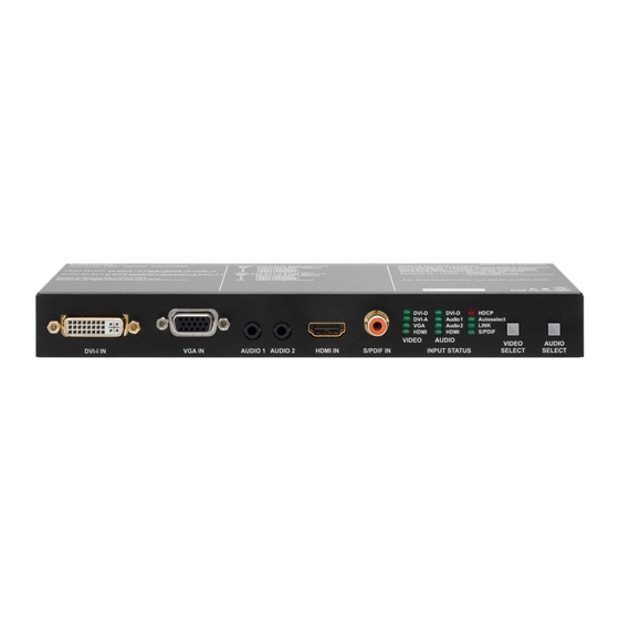
Page 17: Umx-Opt-Tx150R R Ear
UMX-OPT-TX150R has standard RCA receptacles for digital coaxial audio input. ATTENTION! Plugs and sockets on consumer equipment are conventionally color-coded by CEA/CEDIA- 863-B (ANSI) to aid correct connections. According to the standard Lightware uses orange colored RCA connectors for S/PDIF signals. Chapter 3. Product Overview... -
Page 18: Port Diagram
Always use the supplied 5V power adaptor. Warranty is void if damage occurs due to use of a different power source. 3.4. Port Diagram The following figure describes the port diagram of the UMX-OPT-TX150R. 4:1 digital Analog video A/D converter... -
Page 19: Technologies
(in this case SXGA), otherwise the smaller display may not show the higher resolution image. Problem: “I have changed to a different EDID on an input port of the Lightware device to have a different resolution but nothing happens.” Solution: Some graphics cards and video sources read out the EDID only after power-up and later they do not sense that EDID has been changed. -
Page 20: Hdcp Management
(static EDID emulation), or from the last attached monitor's memory (dynamic EDID emulation). For example, the Lightware device can be set up to emulate a sink device, which is connected to one of the outputs. In this case, the EDID automatically changes, if the monitor is replaced with another display device (as long as it has a valid EDID). -
Page 21: Real Life Examples
UMX-OPT-TX150R User’s Manual 4.2.2. Real Life Examples HDCP Compliant Sink Encrypted Encrypted Fiber cable signal signal HDMI/DVI-D HDMI/DVI-D DVI-D DVI-D HDCP DVI-A Audio 1 Autoselect Audio 2 LINK HDMI HDMI S/PDIF VIDEO AUDIO VIDEO AUDIO DVI-I IN VGA IN AUDIO 1 AUDIO 2... -
Page 22: Ixel A Ccurate R Eclocking
Without reclocking, sparkles, noise, and jaggies appear on the image. Lightware’s sophisticated Pixel Accurate Reclocking technology fixes more problems than general TMDS reclocking. It removes not only intra-pair skew but inter-pair skew as well. -
Page 23: Operation Of Umx-Opt-Tx150R
The unit is immediately powered ON. 5.1.1. Firmware Indication After being powered on, the UMX-OPT-TX150R lights up all LEDs from top to bottom, than displays its firmware version using the three upper LEDs of the front panel VIDEO LED bar. - Page 24 AUDIO Status LED (DVI-D, Audio 1, Audio 2, HDMI, S/PDIF) is DVI-D DVI-D HDCP DVI-A Audio1 Autoselect ▪ ON when the audio input port is selected. Audio2 LINK HDMI HDMI S/PDIF VIDEO AUDIO ▪ OFF when the audio input port is NOT selected. Another port is active or there was a disconnect command.
-
Page 25: Led
Video and Audio Select button on the front panel (sections on page 15) ▪ Autoselect mode (section 5.5, 5.6, on pages - 28) ▪ Lightware Device Controller software on page 44) ▪ Protocol command (section on page 58) 5.4.1. Video Input Selection The order of the video selection is shown below. -
Page 26: Ideo Utoselect Ode
5.5. Video Autoselect Mode The Autoselect function means UMX-OPT-TX150R can recognize the incoming valid video on all the input ports and can choose one automatically, without user intervention. Autoselect searching starts after an event. It can be the stepping into Autoselect mode, plugging or unplugging a video or audio cable or appearing or disappearing a valid video signal. - Page 27 HDMI HDMI? select VGA? select User can toggle between the three video Autoselect priority modes with the Lightware Device Controller software (see chapter 6.5.5 on page 51), protocol command (7.4.13 page 65) or the service menu (see chapter 5.10 on page 38).
-
Page 28: Udio A Utoselect M Ode
Priority detect Fix select A2: Analog audio 2 S-A2 S/PDIF User can toggle between the ten audio Autoselect priority modes with the Lightware Device Controller software (see chapter 6.5.5 on page 51), protocol command (see chapter 7.4.15 on page 66) or the service menu (see chapter 5.10... - Page 29 UMX-OPT-TX150R User’s Manual 5.6.2. Non-Priority (First Detect) Result of VIDEO Event autoselect After the video Autoselect the device checks the embedded audio input. Selected DVI-D embedded audio input to the DVI-D video Remains port still has active input or HDMI embedded audio input to the valid video? HDMI video input.
- Page 30 S/PDIF, Embedded, Analog Audio 2 Result of VIDEO Event autoselect After the video Autoselect the device checks the audio inputs in a pre-defined order: First, it checks S/PDIF, then embedded audio and final the analog audio 2 port. ▪ If there is a valid embedded audio signal S/PDIF S/PDIF? select...
-
Page 31: Edid Management
Dynamic EDID (EDID of last connected sink on the DDC output port) ▪ Emulated EDIDs (EDID currently emulated on a specific input port) This manual refers to the EDIDs in two ways. Using, selecting EDIDs with Lightware Device Controller (LDC) software or with Rotary switches. 5.7.1. EDID Memory Stucture... - Page 32 E04 ..........Emulated EDIDs on the HDMI input INFO UMX-OPT-TX150R can handle both 128 Byte EDID and 256 Byte extended EDID structures. EDIDs Are Referred with Rotary Switches In the second case EDID is mentioned with the rear panel rotary switches. EDIDs are numbered from 0 on each rotary, and they can be referred with hash symbol, and the number of the desired EDID.
- Page 33 UMX-OPT-TX150R User’s Manual DVI-A Rotary is in #5 state, it means Factory EDID (Analog) 1920x1200@60 is the selected EDID on the DVI-A input port. DVI-A DVI-A EDID Rotary #0 Copy from SC MM OUT (Dynamic EDID) #1 Factory EDID Universal Analog (default)
- Page 34 EDID becomes active. INFO After every EDID change, UMX-OPT-TX150R toggles the HOT PLUG signal for approx. 1 second. Some graphic cards or DVD players do not sense the HOT PLUG signal, and even if EDID has been changed, the set resolution is not affected. In this case the source device must be restarted, or powered OFF and ON again.
- Page 35 User’s Manual Factory Preset EDID List Lightware factory pre-loaded EDIDs are specially provided to force graphic cards to output only the exact pixel resolution and refresh rate. HDMI and VGA universal EDIDs (#1 on both rotary switches) allow multiple resolutions including all common VESA defined resolutions.
- Page 36 EDID remains in non-volatile memory. 5.7.5. EDID Switching Use a screwdriver to change the memory address on the rear side of the UMX-OPT-TX150R. After any of the rotary switches has been rotated, the unit waits approximately 2 seconds before the selected EDID becomes active.
-
Page 37: Hdcp Management
User’s Manual 5.8. HDCP Management The UMX-OPT-TX150R can work as a HDCP compliant device, or act as a non-HDCP compliant sink. The HDCP capability can be disabled or enabled on the digital video input ports (DVI-D, HDMI). This function helps to apply encryption only when it is mandatory. -
Page 38: Eload Actory Efaults Ervice Enu
RS-232 baud rate options as well. The default operation mode is the PASS mode and the default baud rate is 57600 baud in the UMX-OPT-TX150R. If the previous serial settings differ from the default ones, please set up the neces- sary values after reboot with protocol commands. - Page 39 UMX-OPT-TX150R User’s Manual The menu feedback LEDs are the DVI-A, VGA and HDMI VIDEO LEDs in case of the UMX-OPT-TX150R. The next table contains a detailed example of a binary display. Binary form In binary form Decimal form Menu item...
-
Page 40: Remote Operation
The first value will be selected after the last one. 5.10.3. Saving in the Service Menu The saving time is three seconds in case of the UMX-OPT-TX150R. In the service menu the device saves every value changing after three seconds automatically. If the device exits from service menu (because of a hardware reset) before 3 seconds after a value changing the last modification will be lost. - Page 41 7.4.5 on page 62). INFO UMX-OPT-TX150R stores the RS-232 working mode and starts the saved one after reboot. ATTENTION! The RS-232 settings – baud rate is included – are valid for the Control and the Pass -through mode, as well. For example if the baud rate was changed from 57600 to 9600 in Control mode the device sends commands only with 9600 baud rate in Pass -through mode, as well.
- Page 42 Three types of the touch panel’s commands: ( ): settings of the touch panel / not sent / [ ]: command to the projector / sent via RS-232 to UMX-OPT-TX150R then via fiber optical cable to the projector / { }: command to the UMX-OPT-TX150R / sent via RS-232 to UMX-OPT-TX150R /...
- Page 43 57600, 38400, 19200 or 9600 Baud, 8 bit, 1stop bit, no parity. These settings are fit to the UMX-OPT-TX150R. Button 1 (Power on the projector): The touch panel can control the projector only if the UMX-OPT-TX150R is in pass-through mode. Commands:...
-
Page 44: Software Control - Using Lightware Device Controller
The device can be controlled by a computer through the Ethernet and RS-232 port using Lightware Device Controller (LDC). The software can be installed on a Windows PC or Mac OS X. The application and the User’s manual can be downloaded from www.lightware.eu. - Page 45 Device Discovery Window in LDC INFO Lightware Device Controller software can only connect to the extender if it is in control mode. If the UMX-OPT-TX150R is in pass-through mode, the software cannot communicate with it and cannot list it as an available device. If you want to connect to the extender which is in...
-
Page 46: Rosspoint M Enu
Clicking on this button opens the actual video and audio parameters port properties window. Terminal Clicking on this button opens the Terminal window where the device can be controlled through LW2 protocol commands. Page 46 / 103 Chapter 6. Software Control - Using Lightware Device Controller... -
Page 47: Indow W Indow
These fields are filled automatically by the device after the examination of the signal. 6.4.5. Audio Signal Info Information about the embedded audio signal is shown here (Audio signal, audio type, sampling frequency, channel allocation). Chapter 6. Software Control - Using Lightware Device Controller Page 47 / 103... - Page 48 Horizontal/ Vertical position: Horizontal and vertical position values specify the location of the visible area on the sink device. Black border on any side of the picture can means wrong settings for the position of the visible area. Page 48 / 103 Chapter 6. Software Control - Using Lightware Device Controller...
- Page 49 Just click the Delete record from all ports button. Never mind if the selected preset has different number in the other input properties list, because the device search by the current resolution. Chapter 6. Software Control - Using Lightware Device Controller Page 49 / 103...
- Page 50 Resolution is given by the source devices always means the picture (visible area) resolution and the refresh rate means the VSYNC frequency. If the Refresh button is clicked on then the UMX-OPT-TX150R samples and calculates the analog signal values again.
-
Page 51: Ettings
Fix select (Embedded), ▪ Fix select (Analog 1), ▪ Fix select (Analog 2), ▪ Fix select (S/PDIF), For detailed description about audio Autoselect please read chapter on page Chapter 6. Software Control - Using Lightware Device Controller Page 51 / 103... -
Page 52: Arameters
The source column displays the memory location that the current EDID was routed from. The Dynamic EDID List contains the resolution, manufacturer and vendor name of the display Page 52 / 103 Chapter 6. Software Control - Using Lightware Device Controller... - Page 53 Step 2. Press the Upload button below the Source panel. Step 3. Browse the file in the opening window then press the Open button. Browsed EDID is imported into the selected User memory. Chapter 6. Software Control - Using Lightware Device Controller Page 53 / 103...
- Page 54 All descriptors can be edited, and saved in an EDID file, or uploaded to the User memory. For more details about EDID Editor please visit our website (www.lightware.eu) and download EDID Editor user's manual. Page 54 / 103 Chapter 6. Software Control - Using Lightware Device Controller...
-
Page 55: Settings Menu
Since above mentioned Advanced EDID Editor needs more complex knowledge about EDID, Lightware introduced a wizard-like interface for fast and easy EDID creation. With Easy EDID Creator it is possible to create custom EDIDs in four simple steps. By clicking on the Create button below Source panel, Easy EDID Creator is opened in a new window. - Page 56 Report Section LDC is able to collect information from the device and save it to a report file. This information package can be sent to Lightware support team when a problem may arise with the device. Download report LDC collects the needed information; this may take up to a few minutes.
-
Page 57: Terminal Window
The typed commands can be "browsed" when the cursor is in the command line and you press the up button on the keyboard. The commands are stored until the LDC is closed. Chapter 6. Software Control - Using Lightware Device Controller Page 57 / 103... -
Page 58: Lw2 Programmers' Reference
7. LW2 Programmers’ Reference Users can connect to the extender through serial and USB port. Lightware UMX-OPT-TX150R can be controlled with external devices which can communicate according to the extender protocol. The supported LW2 commands are described in this chapter. -
Page 59: C Ommands
Format Example Command {I} → {i} Response (<PRODUCT_TYPE>)CrLf ← (I:UMX-OPT-TX150R)CrLf Legend: <PRODUCT_TYPE> shows type. Explanation: The connected device is a UMX-OPT-TX150R. 7.3.2. View Serial Number Description: The extender responds its 8-digit serial number. Format Example Command {S} → {s} Response (<SERIAL_NUMBER>)CrLf ←... -
Page 60: System Commands
Slot 0 represents the motherboard. <MB_DESC> The motherboard description contains the name and the version number. Explanation: The extender reports that it has one motherboard called UMX-OPT-TX150R and its version number is V11. 7.3.8. Query All Port Status Description: Shows the actual status of all input and output ports. - Page 61 UMX-OPT-TX150R User’s Manual INFO User can query the protocol only. This command is reserved for compatibility reasons. 7.4.2. Change RS-232 Baud Rate ATTENTION! LW2 commands modify the baud rate only if the rotary switch is set #0. In other case the LW2 commands do not change the baud rate. From #1 to...
- Page 62 RS-232 baud rate options as well. The default operation mode is the PASS mode and the default baud rate is 57600 baud in the UMX-OPT-TX150R. If the previous serial settings differ from the default ones, please set up the necessary values after reboot with protocol commands.
- Page 63 UMX-OPT-TX150R User’s Manual 7.4.6. Query the RS-232 Operation Mode Description: This command queries the current RS-232 operation mode. Format Example Command {RS232=?} → {rs232=?} Response (RS232=<mode>)CrLf ← (RS232=PASS)CrLf Legend: <mode> Two kinds of operation modes can be: <CONTROL> The CPU in the transmitter can receive commands and send responses.
- Page 64 Command {RST} → {rst} Response (Booting…)CrLf ← (Booting…)CrLf (<name>●READY!)CrLf ← (UMX-OPT-TX150R READY!) Legend: <name> is the type of the extender Explanation: The extender reboots and sends a message when it is ready. INFO The response can be seen only if the connection to the extender via RS-232 is still alive. The response cannot be seen and reconnect is always necessary in case of USB connection.
- Page 65 UMX-OPT-TX150R User’s Manual <1> WARNING level events 0 = no immediate message send 1 = immediate message <2> MATTER level events 0 = no immediate message send 1 = immediate message <3> ERROR level events 0 = no immediate message send 1 = immediate message <4>...
- Page 66 7.4.15. Set the Audio Priority Settings Description: This command sets the audio priority order of the Autoselect mode. Format Example Command {AUDIOPRIORITY=<apmode>} → {audiopriority=1} Response (AUDIOPRIORITY=<apmode>)CrLf ← (AUDIOPRIORITY=1)CrLf Legend: <apmode> Ten kinds of audio priority modes can be: <0> Static select: Digital+Embedded, DVI-A+Analog1, VGA+Analog2 <1>...
-
Page 67: Edid R Outer Ommands
UMX-OPT-TX150R User’s Manual 7.5. EDID Router Commands The EDID router manipulates the EDID memory, which has memory locations that are assigned to specific input or output ports. Please read section on page about EDID memory structure. ATTENTION! Emulated EDIDs can be switched with the rotary switches only. - Page 68 Each number represents the EDID validity state for the corresponding memory location. Value Description Invalid EDID Valid EDID Changed EDID Explanation: There is one ‘3’ in the first row on the 1st position. This means that the user EDID is changed since the last EDID query on that port. INFO If a changed EDID is queried by the {WH} command (see the next section), its value returns to ‘1’.
- Page 69 UMX-OPT-TX150R User’s Manual 7.5.6. Upload EDID Content from the Transmitter Description: EDID hex bytes can be written directly to the user programmable memory locations. Sequence: Step 1. Prepare the device to accept EDID bytes to the specified location <loc> with command {WL#<loc>}...
-
Page 70: Ontrol Ommands
Not valid! Factory EDID cannot be deleted. No response. All User EDIDs are deleted. UMX-OPT-TX150R contains only one Dynamic EDID and and it cannot be deleted.. All Emulated EDIDs are selected by rotary switches and they cannot be deleted. Explanation: Third user EDID is cleared from memory. -
Page 71: Ommands
Explanation: The device is in autoselect mode and the VGA input is selected. 7.7. Error Log Related Commands UMX-OPT-TX150R logs the error events into an EPROM memory. The device emulates a standard FAT16 file system with a fix directory and file structure. - Page 72 INFO The drive letter, directory names and file names are given with upper case and the commands are case sensitive. 7.7.1. List a Directory Description: List the content of a directory. Format Example Command {SD_DIR=<path>} → {sd_dir=M:\LOG} Response (DIR1●<cont>)CrLf ← (DIR1 1970_01 <DIR>)CrLf (DIR_END)CrLf ←...
- Page 73 UMX-OPT-TX150R User’s Manual 7.8.1. Set Input Port Properties Description: This command queries the actual state of the autoselect. Format Example Command {:DVII#<in>@<S/A>I=<VIDEO>;<X1>;<X2>;<HDCP>} → {:dvii#1@si=x;x;x;1} Response (DVII#<in>@<S/A>I=<VIDEO>;<X>;<X>; ← (DVII#1@SI=D;x;x; <HDCP>;<STATUS>;<SOURCE>; 1;3;H; <ATIM1/DCS>;<ATIM2/DRES>; 20;1920x1080p60; <ARES/HAUDIO>;<HASAMP><HCH>)CrLf P;48;)CrLf Legend: <S/A>: Affected ports: S = single selected input A = all inputs <VIDEO>:...
- Page 74 Source dependent parameters: Analog signal properties are displayed, when <SOURCE> = R / C: <ATIM1> Analog timing1: 0 = SMTPE standard 1 = User saved preset 2 = EDID detailed timing 3 = Factory preset 4 = GTF formula 5 = User modified (not saved) <ATIM2>...
- Page 75 UMX-OPT-TX150R User’s Manual 0x07 0x08 0x09 0x0A 0x0B 0x0C 0x0D 0x0E 0x0F 0x10 0x11 0x12 0x13 0x14 0x15 0x16 0x17 0x18 0x19 0x1A 0x1B 0x1C 0x1D 0x1E 0x1F Where: Front Left Front Center Front Right Front Left Center Front Right Center...
- Page 76 7.8.3. Set Analog Timing Properties Description: This command changes the setup of the analog timing data. Format Example Command {:ANALOG#<in>@<S/A>I= → {:analog#2@si= <PHS>;<FHS>; 10;2160; <HS>;<VS>; 1600;1200; <HP>;<VP>;} 455;41;} Response (DVII#<in>@<S/A>I= ← (ANALOG#2@SI= <PHS><FHS>; 10;2160; <HS>;<VS>; 1600;1200; <HP>;<VP>; 455;41; <LCF>; 1124; <FORM>;<VSP>;<HSP>;...
- Page 77 UMX-OPT-TX150R User’s Manual 7.8.5. Reset Analog Timing Properties Description: This command resets the analog timing properties. Format Example Command {:ANALOG#<in>@<S/A>I=RESET} → {:analog#2@si=reset} Response (ANALOG#<in>@<S/A>I= ← (ANALOG#1@SI= <PHS>;<FHS>; 0;2160; <HS>;<VS>; 1600;1200; <HP>;<VP>;<LCF>; 455;41;1242; <FORM>;<VSP>;<HSP>;<FPS>)CrLf P;+;+;60;)CrLf Legend: Please read section 7.8.3 on page 76.
- Page 78 7.8.7. Save Analog Color Properties Description: Save analog color properties of the input ports. Format Example Command {:PICTURE#<in>@<S/A>I=SAVE} → {:picture#3@si=save)CrLf Response (P SAVED)CrLf ← (P SAVED)CrLf (PICTURE#<in>@<S/A>I= ← (PICTURE#3@SI= <DF_CHA>;<DF_CHB>;<DF_CHC>; 1023;1023;1023; <G_CHA>;<G_CHB>;<G_CHC>; 1023;1023;1023; <O_CHA>;<O_CHB>;<O_CHC>; 1023;1023;1023; <CONT>;<SAT>;<BRIGHT>;<HUE>;)CrLf 128;128;0;0;)CrLf Legend: Please read section 7.8.6 on page 77.
- Page 79 UMX-OPT-TX150R User’s Manual <GAIN>: Gain: (default 0) 0, 3, 6, .. , 21, 24 dB <POL>: Polarity inversion: (default 0) 0 = Normal (phase=0°), 1= Inverted (phase=180°) <DCF>: Audio DC filter: (default 0) 0 = DC filter off, 1 = DC filter on.
- Page 80 7.8.13. Query the No Sync Picture Properties Description: This command reads the enabling status and the RGB color code of the no sync picture on the active input port. Format Example Command {:SETBG#<in>@<S/A>I=?} → {:SETBG#1@SI=?} Response (SETBG#1@SI= ← (SETBG#1@ <RED>;<GREEN>;<BLUE>;1)CrLf SI=255;255;0;1)CrLf Legend: Please read section 7.8.12...
- Page 81 UMX-OPT-TX150R User’s Manual 7.8.15. Save Preset Description: This command deletes the desired preset from the analog input port. Format Example Command {:AF#<in>@SI=<IPS>} → {:af#2@si=s} Response (AF SAVED)CrLf ← (AF SAVED)CrLf Legend: <IPS> Input port selector: S = Properties will be saved to the current input port.
-
Page 82: Rogperties 7.9. Og Utput P Rogperties
7.8.19. List Presets Description: This command reads and lists all the saved presets from the analog VGA input port. Format Example Command {:AF#<in>@<S/A>I=LIST} → {:af#2@si=list} Response (AF#<in>:<PID>= ← (AF#2:1= <BL>;<LCF>;<FCL>;<LCVS>; 3045;1249;1864;3; <SCN>;<VSPP>;<HSPP>; 0;1;1; <VPL>;<HPP>;<VSL>;<HSP>; 50;495;1200;1600; <FHSP>;<PHS>;)CrLf 2161;23;)CrLf (AF END) ← (AF END) Legend: <S/A>: Affected ports:... -
Page 83: O Utput P Roperties
UMX-OPT-TX150R User’s Manual 7.9. Output Properties The following commands are setting up the properties of the output ports. If only one or a few parameters have to be modified, the protocol enables to mask the other parameters, so they can stay untouched. To mask a parameter use “x” or “X” as its value. - Page 84 Legend for response: G block: General status information <CON> Connection sense: 0 = There is no attached sink device, 1 = Sink device attached (termination is present) <MODE> Output signal mode D = DVI, H = HDMI 24bit, 1 = HDMI 30bit deepcolor 2 = HDMI 36bit deepcolor <SIG>...
-
Page 85: Rror Esponses
UMX-OPT-TX150R User’s Manual <DC>: This field is a number is decimal format. The binary bits show support for different color modes. bit 2 - HDMI deep color 30bits/pixel mode is supported bit 1 - HDMI deep color 36bits/pixel mode is supported... -
Page 86: Ummary
7.11. LW2 Commands - Quick Summary Status and Identification Commands Operation See in chapter Command View Product Type 7.3.1. View Serial Number 7.3.2. View Firmware Version of the CPU 7.3.3. View Installed Controllers’ Firmware 7.3.4. {FC} View Device’s Temperature 7.3.5. {ST} View CPU Firmware Compile Time 7.3.6. - Page 87 UMX-OPT-TX150R User’s Manual Control Commands See in Operation Command chapter Switch One Input to One Output 7.6.1. {<in>@<out>●<A/V/AV>} View All Connections on the Output 7.6.2. {VC●<A/V/AV>} Query Autoselect State 7.6.3. {AUTOSELECT=?} Error Log Related Commands See in Operation Command chapter List a Directory 7.7.1.
-
Page 88: Firmware Upgrade
8. Firmware Upgrade The transmitter can be upgraded by using Lightware Device Updater (LDU) software via USB. The application and the User's manual can be downloaded from www.lightware.eu. In order to get the firmware pack with the necessary components (*.lfp file) for your specific product, please contact support@lightware.eu. - Page 89 About window will appear. Click on the Check now button. The program checks the available updates on Lightware website and shows its version. Step 2. Set the desired update settings in the Options section.
- Page 90 Pressing the button a list will appear showing the supported devices. Click on the Extender button on the main screen. Step 4. Select the package. Click on the Browse button and select the “.lfp” file that will be used for the upgrade. Package information is displayed: ▪...
- Page 91 UMX-OPT-TX150R User’s Manual The following step is to select the desired device(s). The available and supported devices are searched and listed automatically. If the desired device is not listed, update the list by clicking the Refresh button. Select the desired devices: highlight them with a yellow cursor, then click OK.
- Page 92 When you confirmed the warnings, the upgrade process starts automatically. Details button opens a new window where the process is logged – see below. Page 92 / 103 Chapter 8. Firmware Upgrade...
- Page 93 UMX-OPT-TX150R User’s Manual Step 7. Finish. If the upgrade of a device is finished, the log can be opened by the View button on the right When all the tasks are finished, a window appears. Click OK to close and Next to display the summary page.
-
Page 94: Troubleshooting
9. Troubleshooting Usually, if the system seems not to transport the signal as expected, the best strategy for troubleshooting is to check signal integrity through the whole signal chain starting from source side and moving forward to switcher end. At first, check front panel LEDs and take the necessary steps according to their states. For more information about status, LEDs refer to section on page on page 16. - Page 95 UMX-OPT-TX150R User’s Manual Symptom Root cause Action Refer to Video signal Many video sources send HDCP protected signal if they detect that No picture the sink is HDCP capable – even on the video if the content is not copyrighted.
-
Page 96: Appendix
10. Appendix 10.1. Specifications General Compliance .......................CE EMC (Emission) ................EN 55032:2015 EMC (Immunity)................EN 55024:2011 Safety ............. UL, CUL, GS, CR, RCM, PSE, Class II Warranty ....................3 years Cooling ....................Passive Operating temperature ........-20°C ~ +50°C ( -4°F to +122°F ) Operating humidity .......... - Page 97 UMX-OPT-TX150R User’s Manual EDID emulation on video inputs ........Yes, analog and digital S/PDIF Digital audio input ............RCA receptacle Analog audio 1 input ......3.5mm TRS connector (approx. 1/8’’ jack) Analog audio 1 signal type ......... analog stereo, unbalanced Analog audio 2 input ......
- Page 98 H.Sync, V.Sync ......TTL high impedance, automatic pos/neg polarity Scanning frequency, H.Sync ............15 ~ 100 kHz Scanning frequency, V.Sync ............. 50 ~ 100 Hz YPbPr input signal Y (luminance) amplitude, including sync ..........1.0 Vp-p Impedance ....................75 Ω PbPr/CbCr (chroma) amplitude ...............
-
Page 99: Echanical D Rawings
UMX-OPT-TX150R User’s Manual 10.2. Mechanical Drawings The following drawings present the physical dimensions of the device. Dimensions are in Front View DVI-D DVI-D HDCP DVI-A Audio 1 Autoselect Audio 2 LINK HDMI HDMI S/PDIF VIDEO AUDIO VIDEO AUDIO DVI-I IN... -
Page 100: Settings
10.3. Factory Default Settings Parameter Setting/Value Video Port Settings Input port DVI-D HDCP Enabled No sync color Enabled No sync color 7F7F7F (grey) Output video mode Auto Output HDCP mode Auto Video Auto Select Enabled, NonPriority, First detect Audio Auto Select Enabled, First detect: Embedded, S/PDIF, Analog 2 RS-232 Settings Control protocol... - Page 101 UMX-OPT-TX150R User’s Manual Number on DVI-A EDID reference EDIDs for DVI-A Input EDID rotary in protocol User EDID (def.: Univ. Analog EDID) User EDID (def.: Univ. Analog EDID) User EDID (def.: Univ. Analog EDID) Number on VGA EDID reference EDIDs for VGA Input...
-
Page 102: Able
10.5. ASCII Table The most frequently used characters are highlighted. Char Char Char Char [NUL] [Space] [SOH] [STX] " [ETX] [EOT] [ENQ] [ACK] & [BEL] [BS] [TAB] [LF] [VT] [FF] [CR] [SOH] [SI] [DLE] [DC1] [DC2] [DC3] [DC4] [NAK] [SYN] [ETB] [CAN] [EM]... -
Page 103: Istory
Rev. 2.0 16-06-2017 Judit Barsony update Service Menu chapter, update Lightware Device Controller chapter, new Firmware Upgrade chapter, update the table of troubleshooting Chapter 10. Appendix Page 103 / 103...
Need help?
Do you have a question about the UMX-OPT-TX150R and is the answer not in the manual?
Questions and answers