Lightware UMX-OPT-TX150R User Manual
Fiber optical multimedia extender
Hide thumbs
Also See for UMX-OPT-TX150R:
- User manual (107 pages) ,
- Quick start manual (2 pages) ,
- Quick start manual (2 pages)
Table of Contents
Advertisement
Quick Links
Download this manual
See also:
User Manual
Advertisement
Table of Contents

Related Manuals for Lightware UMX-OPT-TX150R


Summary of Contents for Lightware UMX-OPT-TX150R
- Page 1 User’s Manual UMX-OPT-TX150R Fiber Optical Multimedia Extender...
-
Page 2: Important Safety Instructions
UMX-OPT-TX150R – User's Manual Important Safety Instructions Waste Electrical & Electronic Equipment Common Safety Symbols WEEE Class II apparatus construction. This marking shown on the product or its literature, Symbol Description The equipment should be operated only from the power source indicates that it should not be disposed with other indicated on the product. - Page 3 UMX-OPT-TX150R – User's Manual Symbol Legend Document Information This User’s Manual applies to the following versions of the mentioned software, firmware, and hardware: The following symbols and markings are used in the document: Item Version WARNING! Safety-related information which is highly recom-...
-
Page 4: Table Of Contents
2.3.3. Connection Diagram - Examples ..........11 4.10. Service Menu ................23 6.3. Status and Identification Commands ........36 2.3.4. Connecting Serial Devices ............. 11 4.10.1. Enter the Service Menu of UMX-OPT-TX150R ......23 6.3.1. View Product Type ................36 4.10.2. Service Menu Display and Navigation ......... 23 3. PRODUCT OVERVIEW ..............12 6.3.2. View Serial Number ................ - Page 5 UMX-OPT-TX150R – User's Manual 6.5.3. Watch EDID Validity Table ............. 41 8. TROUBLESHOOTING ................58 6.5.4. View EDID Header ................42 9. TECHNOLOGIES ................59 6.5.5. Download EDID Content from the Transmitter ......42 9.1. EDID Management ...............59 6.5.6. Upload EDID Content from the Transmitter ........42 9.1.1. Understanding the EDID ..............
-
Page 6: Introduction
Lightware’s attentive design. The transmitter can both video and audio e.g. VGA, DVI and HDMI 1.3 with analog stereo, be paired with any receiver without restriction. With Lightware’s Hybrid 5.1 S/PDIF and even 7.1 HDMI embedded audio. -
Page 7: Features Of The Device
UMX-OPT-TX150R converts uncompressed analog 1080p 720p, 1080i, 1080p 2K etc. HDTV signals up to 225 MHz Lightware is a legal HDCP adopter. Both HDCP- audio and video signal to digital and places it to the pixel clock frequency are passed through regardless of encrypted and non-HDCP components can be installed output. -
Page 8: Typical Application
1. Introduction UMX-OPT-TX150R – User's Manual 1.5. Typical Application The typical application of the UMX-OPT-TX150R transmitter: Executive boardrooms ▪ Small classrooms ▪ ▪ Conference rooms, collaborative telepresence ▪ Multiroom video and audio control Home theatre systems ▪... -
Page 9: Installation
2. Installation UMX-OPT-TX150R – User's Manual 2.1. Mounting Options To mount the extender Lightware supplies optional accessories for different usage. There are two kinds of mounting kits with similar fixing method. The device has two mounting holes with inner thread on the bottom side; see the bottom view in Mechanical Drawings section. -
Page 10: Connecting Steps
Pin 3: Power RS-232 RD: Received Data (digital input) TD: Transmitted Data (digital output) INFO: UMX-OPT-TX150R is DCE unit according to its pin-out. Different type of serial cables must be used between different serial Power adaptor devices. Touch panel Connect a multimode (OPTM) fiber cable to the SC fiber... -
Page 11: Types Of Serial Cables
Serial cables between devices may have male or female plugs and their type may be straight or null-modem 2.3.3. Connecting Serial Devices in usual. Extender units can be UMX-OPT-TX150R and any compatible Lightware fiber optical receiver device. For ATTENTION! The cable type does not depend on the plug type. more information see the table of Compatible Devices. -
Page 12: Product Overview
3. Product Overview UMX-OPT-TX150R – User's Manual 3.1. UMX-OPT-TX150R - Front View P roduct Overview The following sections are about the physical structure of the device, input/ output ports and connectors: UMX-OPT-TX150R - Front View Ý UMX-OPT-TX150R - Rear View Ý... -
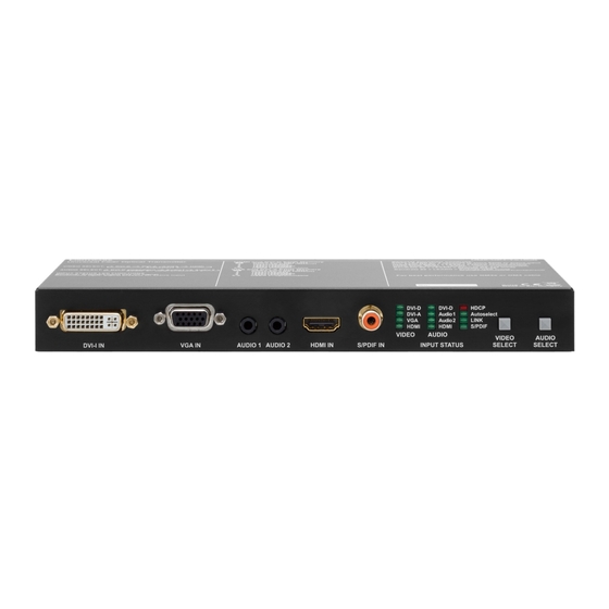
Page 13: Umx-Opt-Tx150R - Rear View
SC MM OUT of the transmitter unit and the SC MM IN of the receiver unit. (e.g. in the selected memory address between #6 .. #9 on the selected input port. To HDMI-3D-OPT-RX100RA or a Lightware Hybrid Matrix equipped with fiber optical learn the EDID, select the desired input and an appropriate address with the rotary input cards). -
Page 14: Electrical Connectors
3. Product Overview UMX-OPT-TX150R – User's Manual 3.3. Electrical Connectors 3.3.6. S/PDIF Input 3.3.8. USB Connector UMX-OPT-TX150R has standard RCA receptacles for digital UMX-OPT-TX150R has standard Mini USB Type B 3.3.1. DVI-I Input coaxial audio input. receptacle. The transmitter unit provides standard ATTENTION! Plugs and sockets on consumer equipment are 3.3.9. DC 5V Connection... -
Page 15: Port Diagram
3. Product Overview UMX-OPT-TX150R – User's Manual 3.4. Port Diagram The following figure describes the port diagram of the UMX-OPT-TX150R. 4:1 digital Analog video A/D converter A/V switch DVI-I in Digital video + Digital audio Digital video... -
Page 16: Operation Of Umx-Opt-Tx150R
After being powered on, the UMX-OPT-TX150R lights up all LEDs from AUDIO Status LED (DVI-D, Audio 1, Audio 2, HDMI, S/PDIF) is Boot up of UMX-OPT-TX150R Ý... -
Page 17: Rear Panel Leds
▪ ON when the TX and the RX (or The order of the video selection is shown below. After the Video Select Audio2 LINK The Autoselect function means UMX-OPT-TX150R can recognize HDMI HDMI S/PDIF OPT-IB) are connected to each button is pushed, the next video input will be chosen. The corresponding... -
Page 18: Hdmi Digital Priority
Lightware User can toggle between the ten audio Autoselect priority modes VGA? Device Controller software (see select with the Lightware Device Controller software (see details in Autoselect Settings chapter), or Embedded Autoselect Settings chapter), or with the Service Menu. -
Page 19: Priority Detect
INFO: The selected audio input will be active until a new result This manual refers to the EDIDs in two ways. Using, selecting EDIDs with of video Autoselect, an audio event or the device exits from the Lightware Device Controller (LDC) software or with Rotary switches. Autoselect mode. -
Page 20: Edid Memory Stucture
EDIDs are numbered from 0 on each rotary, and they can DVI-A In the first case EDID is mentioned with the Lightware Device Controller be referred with hash symbol, and the number of the desired EDID. DVI-A EDID Rotary software or the protocol commands. -
Page 21: Deleting The Edid
Use a screwdriver to change the memory address on the rear side of In addition, HDMI universal EDID also features audio support. The use the UMX-OPT-TX150R. After either one of the rotary switches has been of universal EDID is recommended for fast and easy system setup. -
Page 22: Edid Learning
UMX-OPT-TX150R removes the digital descriptor from the EDID and HDCP key counter is a tool that counts and validates the number of The UMX-OPT-TX150R can work as a HDCP compliant device, or act selects it. keys that can be accepted by a source device when connected to an as a non-HDCP compliant sink. -
Page 23: Service Menu
(menu item) IN BINARY FORM. These LEDs are called menu feedback LEDs. 1st funtion Output mode Auto HDMI 24 The menu feedback LEDs are the DVI-A, VGA and HDMI VIDEO LEDs in case of the UMX-OPT-TX150R. HDCP input mode 2nd function Disable Enable... -
Page 24: Saving In The Service Menu
Step 1. Turn the Baud Rate rotary switch to address #8 connection types (except some rare cases, which are uniquely noted). SELECT button is the value select button in case of the UMX-OPT-TX150R. Step 2. Press and hold the Learn button for approximately 3 seconds. - Page 25 Button 2 (Select the HDMI input): ( ): settings of the touch panel / not sent / The touch panel can only control the UMX-OPT-TX150R if that is in [ ]: command to the projector / sent via RS-232 to UMX-OPT-...
-
Page 26: Software Control - Lightware Device Controller
Windows and the Mac versions have the same look and functionality. 5.1. Install and Upgrade The device can be controlled by a computer through the USB port Lightware Device Controller (LDC). The software can be installed on a Windows PC or Installation for Windows OS Mac OS X. -
Page 27: Establishing The Connection
INFO: Lightware Device Controller software can only connect to the extender if it is in control mode. If the UMX-OPT-TX150R is in pass-through mode, the software cannot communicate with it and cannot list it Audio input ports Each tile represents an audio input port. -
Page 28: Input Parameters Settings Window
5. Software Control – Lightware Device Controller UMX-OPT-TX150R – User's Manual 5.4. Input Parameters Settings Window INFO: These fields are filled automatically by the device after the examination of the signal. 5.4.5. Audio Signal Info By clicking on the Input parameters button a dialog window appears showing the parameters for the active input. -
Page 29: Frame Detector
Save to this input: Preset assigned for the current resolution will be set record from all ports button. Never mind if the selected preset has If the Refresh button is clicked on then the UMX-OPT-TX150R samples to the actual input. -
Page 30: Output Parameters Settings Window
5. Software Control – Lightware Device Controller UMX-OPT-TX150R – User's Manual 5.5.5. Autoselect Settings Click on the Close button to close the Frame detector window and step back to the current input port settings window. Video Auto Select INFO: The frame detector only gives information about video signal The video Autoselect settings are available in this drop-down menu. -
Page 31: Edid Menu
5. Software Control – Lightware Device Controller UMX-OPT-TX150R – User's Manual 5.6. EDID Menu 5.6.1. EDID Operations After the list is downloaded, the current status is shown. The EDID memory consists of four parts. EDID management can be accessed by selecting the EDID menu. There are two panels: left one contains Source EDIDs, right one contains Destination places where the EDIDs can be emulated or copied. -
Page 32: Edid Summary Window
Previously saved EDID (*.bin, *.dat or *.edid file) can be uploaded to the user memory: visit our website (www.lightware.eu) and download EDID Editor user's manual. Step 1. Press the User button on the top of the Source panel and select a memory slot. -
Page 33: Creating An Edid
LDC is able to collect information from the device and save it to a report file. This information package can The serial number, installed firmware version and the hardware revision of the device is shown under the be sent to Lightware support team when a problem may arise with the device. Device Information tab. -
Page 34: Terminal Window
5.8. Terminal Window Generate Report From File The LDC is able to send a custom command file to UMX-OPT-TX150R. The command file can be generated This general purpose terminal is intended mainly for testing and debugging purposes. All commands can be by Lightware support. -
Page 35: Lw2 Programmers' Reference
6. LW2 Programmers’ Reference UMX-OPT-TX150R – User's Manual 6.1. Serial Port Settings UMX-OPT-TX150R uses RS-232 communication port. D-SUB connector pin assignments can be found in RS-232 Port chapter. The device uses standard RS-232 interface with the following default settings: 57600 Baud, 8 data bit, 1 stop bit, no parity... -
Page 36: Status And Identification Commands
6.3.4. View Installed Controllers’ Firmware <MB_DESC> The motherboard description contains the name and the version number. Description: Shows the firmware revisions of the installed controllers. Explanation: The extender reports that it has one motherboard called UMX-OPT-TX150R and its version Format Example number is V11. -
Page 37: Query All Port Status
6. LW2 Programmers’ Reference UMX-OPT-TX150R – User's Manual 6.3.8. Query All Port Status Possible settings: <rate> Baud rate Description: Shows the actual status of all input and output ports. 9600 9600 baud 19200 19200 baud Format Example... -
Page 38: Reload Factory Defaults
The default operation mode is the PASS mode and the default baud rate is Explanation: HDCP key cache is cleared. 57600 baud in the UMX-OPT-TX150R. If the previous serial settings differ from the default ones, please set up the necessary values after reboot with protocol commands. -
Page 39: Count Hdcp Keys
6. LW2 Programmers’ Reference UMX-OPT-TX150R – User's Manual 6.4.8. Count HDCP Keys 6.4.10. View Error List Description: If there is an HDCP source on the HDMI input of the device, the device can ask the source Description: Shows the basic error list since last boot up. -
Page 40: Configure Remote Alerts
6. LW2 Programmers’ Reference UMX-OPT-TX150R – User's Manual 6.4.11. Configure Remote Alerts 6.4.13. Set the Video Priority Settings Description: The device logs different levels of errors. Configure which level of errors has to be sent out as Description: This command sets the video priority order of the Autoselect mode. -
Page 41: Set The Audio Priority Settings
6. LW2 Programmers’ Reference UMX-OPT-TX150R – User's Manual 6.4.15. Set the Audio Priority Settings 6.5.1. Save EDID to User Memory (Learn EDID) Description: This command sets the audio priority order of the Autoselect mode. Description: Learn EDID from <loc2> to <loc1>. -
Page 42: View Edid Header
6. LW2 Programmers’ Reference UMX-OPT-TX150R – User's Manual 6.5.5. Download EDID Content from the Transmitter INFO: <type> can be only capital letter. Each number represents the EDID validity state for the corresponding memory location. Description: EDID hex bytes can be read directly. The transmitter will issue the whole content of the EDID present on memory location <loc>... -
Page 43: Delete Edid From Memory
V: Video layer AV: Audio&Video layer UMX-OPT-TX150R contains only one Dynamic EDID and and it cannot be deleted.. All Emulated EDIDs are selected by rotary switches and they cannot be deleted. <in> must be 1, 2, 3, 4 or 5 in case of video input 1: DVI-D video input Explanation: Third user EDID is cleared from memory. -
Page 44: View All Connections On The Output
Explanation: The device is in autoselect mode and the VGA input is selected. structure. 6.7. Error Log Related Commands Format Example UMX-OPT-TX150R logs the error events into an EPROM memory. The device emulates a standard FAT16 file Command {SD_Format} → {sd_Format} system with a fix directory and file structure. -
Page 45: Input Properties
6. LW2 Programmers’ Reference UMX-OPT-TX150R – User's Manual 6.8. Input Properties <STATUS> Status (hexadecimal): bit 0: (LSB): Power 5V The following commands are setting up the properties of the input ports. If only one or a few parameters 0 = not detected have to be modified, the protocol enables to mask the other parameters, so they can stay untouched. -
Page 46: Query Input Port Properties
6. LW2 Programmers’ Reference UMX-OPT-TX150R – User's Manual If HDMI signal present <SOURCE> = H, there are more HDMI specific parameters: 0x16 0x17 <HAUDIO> HDMI Audio properties: 0x18 0 = no audio 0x19 P = 2 channel stereo (L-PCM) -
Page 47: Set Analog Timing Properties
6. LW2 Programmers’ Reference UMX-OPT-TX150R – User's Manual 6.8.3. Set Analog Timing Properties 6.8.5. Reset Analog Timing Properties Description: This command changes the setup of the analog timing data. Description: This command resets the analog timing properties. Format... -
Page 48: Save Analog Color Properties
6. LW2 Programmers’ Reference UMX-OPT-TX150R – User's Manual 6.8.10. Set Analog Input Audio Parameters INFO: Analog color setting will not be saved automatically. User can save it with the next command. 6.8.7. Save Analog Color Properties Description: This command changes the setup of the ADC on the audio board. -
Page 49: Set The No Sync Picture Properties
6. LW2 Programmers’ Reference UMX-OPT-TX150R – User's Manual 6.8.12. Set the No Sync Picture Properties 6.8.14. Query Timings of the Incoming Signal Description: If there is no incoming video signal on the selected input and this function is enabled the device Description: This command reads out the properties of the incoming signal on the selected input ports. -
Page 50: Save Preset
6. LW2 Programmers’ Reference UMX-OPT-TX150R – User's Manual 6.8.15. Save Preset 6.8.19. List Presets Description: This command deletes the desired preset from the analog input port. Description: This command reads and lists all the saved presets from the analog VGA input port. -
Page 51: Delete Preset From All Input Ports
6. LW2 Programmers’ Reference UMX-OPT-TX150R – User's Manual 6.8.20. Delete Preset from All Input Ports Legend for command: O block: Actual output settings <S/A> Affected ports: <MODE>: Same as in G block. Description: This command deletes the desired from all analog input S = single-selected output <CSPAC>:... -
Page 52: Query Output Video Properties
6. LW2 Programmers’ Reference UMX-OPT-TX150R – User's Manual 6.9.2. Query Output Video Properties 6.11. LW2 Commands - Quick Summary Description: Displays the status for output port. Status and Identification Commands Format Example Operation See in chapter Command Command {:HDMI#<out>@<S/A>O=?} →... - Page 53 6. LW2 Programmers’ Reference UMX-OPT-TX150R – User's Manual EDID Router Commands See in Operation Command chapter Operation See in chapter Command Set Analog Color Properties 6.8.6 {:PICTURE#<in>@<S/A>I= <DF_CHA>;<DF_CHB>;<DF_CHC>;<G_CHA>; Save EDID to User Memory (Learn EDID) 6.5.1 {<loc1>:<loc2>}...
-
Page 54: Firmware Upgrade
About window will appear. products by giving a few tips on how to start and by explaining the features of Step 1. Get the firmware pack and the Lightware Device Updater (LDU) Click on the Check now button. The program checks the available the Lightware Device Updater (LDU) software. -
Page 55: Establish The Connection
7. Firmware Upgrade UMX-OPT-TX150R – User's Manual ▪ If you do not want to check for the updates automatically, uncheck the circle, which contains the green Click on the Browse button and select the “.lfp” file that will be used for the upgrade. - Page 56 7. Firmware Upgrade UMX-OPT-TX150R – User's Manual Step 4. Select the device. Firmware Components The firmware components of the selected devices are listed on the following screen: installed and update versions. (Update version will be uploaded to the device.) The following step is to select the desired device(s).
- Page 57 7. Firmware Upgrade UMX-OPT-TX150R – User's Manual Step 5. Upgrade the device. Details button opens a new window where the process is logged – see below. A warning window will pop up before starting upgrading the device: ▪...
-
Page 58: Troubleshooting
8. Troubleshooting UMX-OPT-TX150R – User's Manual Symptom Root cause Action Refer to Video signal Device(s) not powered Check the extenders and the other devices if they are properly powered; try to unplug and 3.3.9 properly reconnect them. -
Page 59: Technologies
(dynamic EDID emulation). information about additional Detailed Timings, audio capabilities, For Example, the Lightware device can be set up to emulate a sink speaker allocation and HDMI capabilities. It is important to know that device, which is connected to one of the outputs. -
Page 60: Hdcp Management
HDCP enabling/disabling function: the HDCP capability can be replace the display device to an HDCP-capable one. disabled in the Lightware device. If HDCP is disabled, the connected Jitter source will detect that the sink is not HDCP capable, and turn off 9.3. Pixel Accurate Reclocking... -
Page 61: Appendix
10. Appendix UMX-OPT-TX150R – User's Manual 10.1. Specification Audio and video inputs HDMI input ......... 19-pole HDMI Type A receptacle General Reclocking on HDMI input ....Yes, Pixel Accurate Reclocking Compliance ..................CE DVI-I connector ........29-pole, DVI-I digital and analog EMC (Emission) ............. -
Page 62: Factory Default Settings
10. Appendix UMX-OPT-TX150R – User's Manual 10.2. Factory Default Settings Digital video signal H.Sync, V.Sync ..TTL high impedance, automatic pos/neg polarity Signal standard ........HDMI standard which supports: Scanning frequency, H.Sync ..........15 ~ 100 kHz Parameter Setting/Value .................... -
Page 63: Factory Edid List
10. Appendix UMX-OPT-TX150R – User's Manual 10.3. Factory EDID List INFO: Minor changes in the factory EDID list may be applied in further firmware versions. The Emulated EDIDs on the video inputs can be chosen by rotary... -
Page 64: Mechanical Drawings
10. Appendix UMX-OPT-TX150R – User's Manual 10.4. Mechanical Drawings 10.5. ASCII Table The following drawings present the physical dimensions of the device. Dimensions are in mm. The most frequently used characters are highlighted. Front View Char Char Char... -
Page 65: Further Information
1.4. Product failures from six (6) months to the end of the warranty period will either be repaired or replaced at the discretion of Lightware. If Lightware chooses to replace the product then the replacement will be warranted for the remainder of the original unit’s warranty period.
Need help?
Do you have a question about the UMX-OPT-TX150R and is the answer not in the manual?
Questions and answers