Lightware UBEX-PRO20-HDMI-F100 User Manual
Hide thumbs
Also See for UBEX-PRO20-HDMI-F100:
- User manual (253 pages) ,
- Installation and network setup manual (36 pages) ,
- User manual (201 pages)
Table of Contents
Advertisement
Quick Links
Advertisement
Table of Contents
Troubleshooting

Related Manuals for Lightware UBEX-PRO20-HDMI-F100


Summary of Contents for Lightware UBEX-PRO20-HDMI-F100
- Page 1 User’s Manual Extender Application Mode UBEX-PRO20-HDMI-F100 UBEX-PRO20-HDMI-F110 UBEX-PRO20-HDMI-R100 2xMM-2xDUO UBEX-PRO20-HDMI-R100 2xMM-QUAD UBEX-PRO20-HDMI-R100 2xSM-2xDUO UBEX-PRO20-HDMI-R100 2xSM-QUAD UBEX-PRO20-HDMI-R100 2xSM-BiDi-DUO AV Over IP Multimedia Extender v2.1 18-06-2021 ...
- Page 2 series – Extender Application Mode – User's Manual Important Safety Instructions Waste Electrical & Electronic Equipment Common Safety Symbols WEEE Class I apparatus construction. Symbol Description This marking shown on the product or its literature, This equipment must be used with a mains power system with a indicates that it should not be disposed with other protective earth connection.
- Page 3 The following symbols and markings are used in the document: All presented functions refer to the indicated products. The Lightware Visual Engineering supports green technologies and descriptions have been made during testing these functions in eco-friend mentality. Thus, this document is made for digital usage...
- Page 4 #dhcp This keyword is placed at the DHCP (dynamic IP address) setting in the front panel operation, the Lightware Device Controller (LDC) and the LW3 programmer's reference section. See the list of all hashtag keywords of the document in the...
-
Page 5: Table Of Contents
4.6.4. Connection between Neutrik opticalCON DUO BiDi Connectors . 44 1.2. Box Contents ................10 3.7.3. Save ....................28 4.7. Connection between F-series and R-series Endpoints ....44 1.2.1. UBEX-PRO20-HDMI-F100 / F110 ........... 10 3.8. System Status Menu ..............28 4.7.1. SFP+ to Neutrik opticalCON DUO ..........44 1.2.2. UBEX-PRO20-HDMI-R100 Series ........... 11 3.9. System Settings Menu ...............29... - Page 6 6.11. Settings Menu ................89 7.4.17. Restarting the Device ..............101 6.11.1. Status Tab ..................89 7.4.18. Restore the Factory Default Settings ........101 6. LIGHTWARE DEVICE CONTROLLER (LDC) ........69 6.11.2. Network Tab .................. 89 7.5. Video Port Settings - Transmitter Mode ........101 6.1. Install and Update ..............70 6.11.3. Front Panel Tab ................
- Page 7 series – Extender Application Mode – User's Manual Table of Contents 7.6.15. Enable Signal Freeze ..............109 7.9.4. Setting the Gain ................121 7.14.3. Parity Setting ................127 7.6.16. Disable Signal Freeze ..............110 7.9.5. Mute/Unmute the Analog Audio Output Port ......121 7.14.4. Stopbits Setting ................
- Page 8 12.2.1. F-series Endpoints ..............164 12.2.2. R-series Endpoint ............... 164 12.3. Input/Output Port Numbering ..........164 12.3.1. UBEX-PRO20-HDMI-F100 / R100 - Transmitter Mode ....164 12.3.2. UBEX-PRO20-HDMI-F100 / R100 - Receiver Mode ....164 12.3.3. UBEX-PRO20-HDMI-F100 / R100 - Transceiver Mode ....165 12.3.4. UBEX-PRO20-HDMI-F110 - Transmitter Mode ......165 12.3.5. UBEX-PRO20-HDMI-F110 - Receiver Mode .......
-
Page 9: Introduction
– Extender Application Mode – User's Manual I ntroduction Thank you for choosing Lightware’s UBEX families extender. In the first chapter we would like to introduce the device highlighting the most important features in the following sections: ç Description ç... -
Page 10: Description
– Extender Application Mode – User's Manual 1.1. Description About the Serial Number Lightware devices contain a label indicating the unique serial number of the product. The structure is the Lightware’s one of the most visionary development project is following: the UBEX (Ultra Bandwidth Extender) product family. -
Page 11: Ubex-Pro20-Hdmi-R100 Series
Pixel Accurate Reclocking The following items can be purchased optionally for the indicated device. Each output has a clean, jitter free signal, eliminating signal instability and distortion caused by UBEX-PRO20-HDMI-F100 / F110 long cables or connector reflections. Scaling the Output Image Video scaling is the process of changing the size of a video frame in order to match the native resolution of a display sink. - Page 12 Open API Open-source API technology at the core makes these Lightware products easy to integrate into third-party systems. Every bit of data in Lightware systems is openly available for higher level management and monitoring systems. Applied F-series endpoint firmware package: v2.0.0 | Applied R-series endpoint firmware package: v2.0.0 | LDC software: v2.5.9b3...
-
Page 13: Model Comparison
Video ports Audio ports Interface ports Multimode Singlemode Ethernet UBEX-PRO20-HDMI-F100 (2x) UBEX-PRO20-HDMI-F110 (3x) ... -
Page 14: Application Modes
Management Unit (MMU) which controls the AV network. The user's manual of the UBEX Matrix mode can be downloaded from the following link: #matrixmode https://lightware.com/media/lightware/filedownloader/file/User-Manual/UBEX_Matrix_ UsersManual.pdf INFO: The Extender or Matrix mode is set automatically in the endpoint device. If the device detects direct... -
Page 15: Transceiver-Transceiver Pair
Two UBEX transceivers are connected each other via 400 m fiber optical cables. The UBEX-PRO20-HDMI-F100 transceiver connects to a D3 media server which is the source and the sink device together. The incoming stream can be checked locally on the local monitor. -
Page 16: Product Overview
2. Product Overview 2. Product Overview series – Extender Application Mode – User's Manual series – Extender Application Mode – User's Manual P roduct Overview The following sections are about the physical structure of the device, input/ output ports and connectors; software and hardware capabilities: ç... -
Page 17: Front And Rear View - F-Series Endpoint Devices
Front panel LCD menu - see the details in the Front Panel section; ▪ Lightware Device Controller (LDC) software / Built-in website - see the details in the Front Panel Tab section; Reset button Reboots the device (the same as disconnecting from the power source and ▪... -
Page 18: Rear View
HDMI output ports HDMI output ports with HDMI 2.0 support for sink devices. When the device UBEX-PRO20-HDMI-F100 is configured as transmitter, the both ports operate as local HDMI outputs. When the device is configured as transceiver, the HDMI out 2 port operate as local HDMI output. -
Page 19: Front And Rear View - R-Series Endpoint Devices
The function can be enabled by the following methods: ▪ Lightware Device Controller (LDC) software / Built-in website - see the details in the Front Panel Tab section; Lightware Device Controller (LDC) software - see the details in the Front ▪... -
Page 20: Rear View
2. Product Overview 2. Product Overview series – Extender Application Mode – User's Manual series – Extender Application Mode – User's Manual 2.2.2. Rear View Neutrik powerCON Neutrik powerCON TRUE1 NAC3MPX-WOT connector accepting 100-240 V, UBEX-PRO20-HDMI-R100 2xMM-QUAD and 2xSM-QUAD AC connector 50 or 60 Hz. -
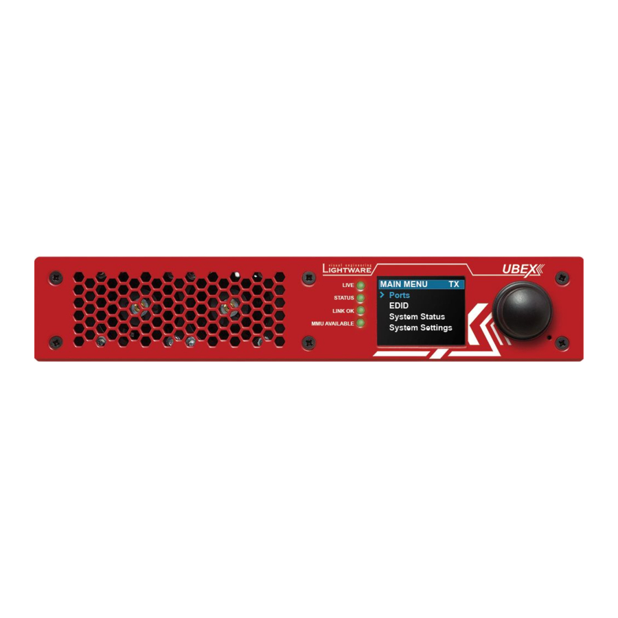
Page 21: Front Panel Lcd Menu Operations
3. Front Panel LCD Menu Operations 3. Front Panel LCD Menu Operations series – Extender Application Mode – User's Manual series – Extender Application Mode – User's Manual F ront Panel LCD Menu Operations This chapter is about the operating of the device describing the functions which are available by the front panel controls: ç... -
Page 22: The Tree Structure Of The Lcd Menu
3. Front Panel LCD Menu Operations 3. Front Panel LCD Menu Operations series – Extender Application Mode – User's Manual series – Extender Application Mode – User's Manual 3.1. The Tree Structure of the LCD Menu HOME SCREEN HOME SCREEN HOME SCREEN... -
Page 23: Introduction
The color of the header is blue for the transmitter, white for the receiver, and black with a white stripe for The device label can be modified by the following methods: the transceiver; ▪ Using the Lightware Device Controller (LDC) software - see the details in the Status Tab section. ▪... -
Page 24: Ports Menu - Transmitter Operation Mode
3. Front Panel LCD Menu Operations 3. Front Panel LCD Menu Operations series – Extender Application Mode – User's Manual series – Extender Application Mode – User's Manual 3.4. Ports Menu - Transmitter Operation Mode Video Settings The following settings can be set in the case of both input ports: The most important settings and status information of the HDMI ports are... -
Page 25: Tx O1 And Tx O2 Ports
3. Front Panel LCD Menu Operations 3. Front Panel LCD Menu Operations series – Extender Application Mode – User's Manual series – Extender Application Mode – User's Manual 3.4.3. TX O1 and TX O2 Ports Stream Output The following information is displayed in the case of both input ports of the transmitter: The following information is displayed for both local output ports:... -
Page 26: Rx I1 And Rx I2 Ports
3. Front Panel LCD Menu Operations 3. Front Panel LCD Menu Operations series – Extender Application Mode – User's Manual series – Extender Application Mode – User's Manual 3.6. Ports Menu - Transceiver Operation Mode HDMI Output The following information are displayed in the case of both output ports of the receiver: #hdcp #power5v... -
Page 27: L (Local) Trx O1 Port
3. Front Panel LCD Menu Operations 3. Front Panel LCD Menu Operations series – Extender Application Mode – User's Manual series – Extender Application Mode – User's Manual Stream Output HDMI Output The following settings and information is related to the video stream which is sent toward the remote TRX The following information are displayed for the HDMI output 2 port of the transceiver: #hdcp #power5v... -
Page 28: L (Local) Trx O2 Port
3. Front Panel LCD Menu Operations 3. Front Panel LCD Menu Operations series – Extender Application Mode – User's Manual series – Extender Application Mode – User's Manual 3.6.5. L (Local) TRX O2 Port 3.7.2. Switch The following information is displayed for the local output port: INFO:... -
Page 29: System Settings Menu
3. Front Panel LCD Menu Operations 3. Front Panel LCD Menu Operations series – Extender Application Mode – User's Manual series – Extender Application Mode – User's Manual 3.9.3. Application Mode Temperatures The recent temperature of the CPU, the system, and the FPGA are displayed in the menu. The current application mode (Extender or Matrix) is displayed in this submenu. -
Page 30: Installation
4. Installation 4. Installation series – Extender Application Mode – User's Manual series – Extender Application Mode – User's Manual I nstallation The chapter is about the installation of the device and connecting to other appliances, presenting also the mounting options and further assembly steps: ç... -
Page 31: Mounting Options - F-Series Endpoint Devices
1U high rack shelf provides mounting INFO: The endpoint device is half-rack sized. holes for fastening two half-rack or To order mounting accessories please contact sales@lightware.com. four quarter-rack sized units. Pocket sized devices can also be fastened 4.1.1. Mounting Bracket V2 on the self. -
Page 32: Mounting Options - R-Series Endpoint Devices
Mounting thread on top and on one of the sides for safe and secure installation. Rigging the handles with a safety wire rope is highly recommended for safety reasons. To order mounting accessories please contact sales@lightware.com. (Truss clamp and safety wire rope are not available at sales.) Step 2. - Page 33 4. Installation 4. Installation series – Extender Application Mode – User's Manual series – Extender Application Mode – User's Manual ATTENTION! Take care of the mounting direction of the screws! Step 4. As a final step, mount the unit in the rack. Mounting direction of the screws Step 3.
-
Page 34: Electrical Connections
4. Installation 4. Installation series – Extender Application Mode – User's Manual series – Extender Application Mode – User's Manual 4.3. Electrical Connections 4.3.3. HDMI Connector The endpoint device provides standard 19-pole HDMI connector for inputs and outputs with The following sections describe all possible electrical connections of the UBEX endpoint devices. -
Page 35: Ethernet Connectors
Does not intermate with CAT6 cable connector NE8MC6-MO and NKE6S* cables. Number of connectors Wiring of LAN Cables Lightware recommends the termination of LAN cables on the basis of TIA/EIA T 568 A or TIA/EIA T 568 B standards. Connector drawing Bottom... -
Page 36: Ir Connector
4. Installation 4. Installation series – Extender Application Mode – User's Manual series – Extender Application Mode – User's Manual 4.3.8. IR Connector IR detector and IR emitter can be connected to the endpoint device with TRS (Tip, Ring, and Sleeve) connectors. -
Page 37: Connections
LCD menu - see the details in the Operation Mode section; ▪ via Lightware Device Controller (LDC) software - see the details in the Status Tab section; RS-232 Optionally for RS-232 extension: connect the controlled unit (e.g. 4K TV) to the ▪... -
Page 38: F-Series Endpoints - Receiver Operation Mode
▪ WARNING! User Ethernet is also transmitted over the SFP+ interface so be sure not to create network ▪ via Lightware Device Controller (LDC) software - see the details in the Status Tab section; loop. ▪ via LW3 protocol command - see the details in the Set the Operation Mode section. -
Page 39: F-Series Endpoints - Transceiver Operation Mode
RS-232 Optionally for RS-232 extension: connect the controlled unit (e.g. 4K TV) to the ▪ via Lightware Device Controller (LDC) software - see the details in the Status Tab section; RS-232 port of the device with a serial cable. -
Page 40: R-Series Endpoints - Transmitter Operation Mode
LCD menu - see the details in the Operation Mode section; ▪ via Lightware Device Controller (LDC) software - see the details in the Status Tab section; ▪ via LW3 protocol command - see the details in the Set the Operation Mode section. -
Page 41: R-Series Endpoints - Receiver Operation Mode
LCD menu - see the details in the Operation Mode section; ▪ via Lightware Device Controller (LDC) software - see the details in the Status Tab section; ▪ via LW3 protocol command - see the details in the Set the Operation Mode section. -
Page 42: R-Series Endpoints - Transceiver Operation Mode
The operation mode of the UBEX endpoint device can be changed using the following methods: ▪ via front panel LCD menu - see the details in the Operation Mode section; via Lightware Device Controller (LDC) software - see the details in the Status Tab section; ▪ ▪... -
Page 43: Sfp+ Slot Connection
UBEX endpoint devices use SFP+ modules for the fiber optical connections. Affected models: The optical modules can be changed based on the current application of the ▪ UBEX-PRO20-HDMI-F100 extender: it can be singlemode or multimode, or BiDi modules, up to 10 GbE ▪ UBEX-PRO20-HDMI-F110 signal transmission. -
Page 44: Connection Between Neutrik Opticalcon Duo Connectors
DUO connectors like in the illustration on the right. F-series endpoint model R-series endpoint model ATTENTION! Always check the direction of the UBEX-PRO20-HDMI-F100 UBEX-PRO20-HDMI-R100 2xMM-2xDUO optical signal. The Port A must be connected to the UBEX-PRO20-HDMI-F110 UBEX-PRO20-HDMI-R100 2xSM-2xDUO Port B. -
Page 45: Sfp+ To Neutrik Opticalcon Quad
Required fiber optical equipment for connecting an F110 and an R100 QUAD endpoint device F-series endpoint model R-series endpoint model INFO: This method does not work in case of using DAC cables in the F-series endpoint device. UBEX-PRO20-HDMI-F100 UBEX-PRO20-HDMI-R100 2xMM-QUAD 4.7.3. SFP+ BiDi to Neutrik opticalCON DUO BiDi UBEX-PRO20-HDMI-F110 UBEX-PRO20-HDMI-R100 2xSM-QUAD... -
Page 46: Startup Of The System
LDC software, in the Device discovery window - see the details in the Establishing the Connection section. Lightware Device Controller Software All required settings can be done by control software, the Lightware Device Controller (LDC). See all the details about it in the Lightware Device Controller (LDC) chapter. -
Page 47: Check The Signal Status
4. Installation 4. Installation series – Extender Application Mode – User's Manual series – Extender Application Mode – User's Manual 4.8.4. Check the Signal Status SFP+ Links Check the connection status of the SFP+ links: The Crosspoint menu in the LDC software displays all important information about the incoming, transmitting, and outgoing HDMI signals. -
Page 48: Set The Hdcp Settings
4. Installation 4. Installation series – Extender Application Mode – User's Manual series – Extender Application Mode – User's Manual 4.8.6. Set the HDCP Settings Example For HDMI in 1 Check the HDCP settings either on the input and output ports. For more details about the HDCP technology see the HDCP Management section. -
Page 49: Set The Scaler And The Frame Rate Converter
4. Installation 4. Installation series – Extender Application Mode – User's Manual series – Extender Application Mode – User's Manual 4.8.8. Set the Scaler and the Frame Rate Converter 4.8.9. Set the Audio Streams Set up the scaler and the frame rate converter (FRC) for the best user experience. -
Page 50: Checkpoints For The Seamless Switching
▪ Set the color range: if the color ranges of the signal source devices are different, this setting helps adjusting between the different types. Lightware recommends the following settings for the color range: – If the color range of the signal source devices are the same: set to No conversion (default). -
Page 51: Ubex Concept
5. UBEX Concept 5. UBEX Concept series – Extender Application Mode – User's Manual series – Extender Application Mode – User's Manual U BEX Concept The following chapter describes the features of the device with few real-life examples. The topics that are described: ç... -
Page 52: Video Interface
HDMI input 2 port. The port diagram is valid for the following UBEX endpoint models: Fiber Optical Interface ▪ UBEX-PRO20-HDMI-F100 After the Ethernet packetizing the two video streams are transmitted to the remote endpoint device via the ▪ UBEX-PRO20-HDMI-F110 SFP+ / fiber optical ports. -
Page 53: Receiver Mode
The type of sources is different for the two outputs. The port diagram is valid for the following UBEX endpoint models: HDMI out 1 ▪ UBEX-PRO20-HDMI-F100 ▪ Able to accept signal up to 4K@60 4:4:4 resolution via the SFP+ links from the remote endpoint device; ▪... -
Page 54: Transceiver Mode
The port diagram is valid for the following UBEX endpoint models: The HDMI out 1 transmits the HDMI signal coming from the remote UBEX endpoint. The video stream can ▪ UBEX-PRO20-HDMI-F100 be processed in the video processor (it contains scaler, frame rate converter (FRC) and color space converter (CSC) ▪... -
Page 55: Hdmi Signal Transmission - Example For Tx-Rx Pair
The scaler is available on the receiver and transmitter side either. The stream of the HDMI in 1 can be re- scaled and the transmitter transmits the optimized stream toward the receiver. Lightware Device Controller (LDC) The crosspoint settings are available in LCD menu of the device (see the details in the... -
Page 56: Hdmi Signal Transmission - Example For Trx-Trx Pair
5. UBEX Concept 5. UBEX Concept series – Extender Application Mode – User's Manual series – Extender Application Mode – User's Manual 5.1.5. HDMI Signal Transmission - Example for TRX-TRX Pair Available HDMI Signal Routing Destinations Transceiver #1 Transceiver #2... -
Page 57: Timing Modes
5. UBEX Concept 5. UBEX Concept series – Extender Application Mode – User's Manual series – Extender Application Mode – User's Manual 5.1.6. Timing Modes Application of Timing Mode Settings - Example Technical Background UBEX receivers and transceivers provide two different timing modes on the HDMI outputs: ▪... -
Page 58: Bandwidth Limitation
5. UBEX Concept 5. UBEX Concept series – Extender Application Mode – User's Manual series – Extender Application Mode – User's Manual 5.1.7. Bandwidth Limitation 5.1.8. The Difference between the Scaler and the FRC - Example The UBEX endpoints can transmit two video streams at the same time up to 20 Gbps bandwidth. -
Page 59: The Difference Between The Image Positions Of The Scaler
The port diagram is valid for the following UBEX endpoint model: The aspect ratio of the original stream and the sink device are different in the following examples. ▪ UBEX-PRO20-HDMI-F100 Stretch ▪ UBEX-PRO20-HDMI-R100 The aspect ratio of the stream is distorted because it is adjusted to the aspect ratio of the sink. -
Page 60: Transceiver Mode - F100/R100 Models
Source Multiplexer (MUX) ▪ UBEX-PRO20-HDMI-F100 INFO: The source MUX function can be set on the video side only in the Lightware Device Controller (LDC ▪ UBEX-PRO20-HDMI-R100 series software and using LW3 protocol commands as well. The source multiplexer (Source MUX) makes available routing more different source signals to the HDMI output ports. -
Page 61: Transmitter Mode - F110 Model
5. UBEX Concept 5. UBEX Concept series – Extender Application Mode – User's Manual series – Extender Application Mode – User's Manual Connection with an F110 Endpoint Device Signal Support of the Analog Audio Output When the F100/R100 transceiver connects to an F110 endpoint device, the port diagram changes due to the The UBEX-PRO20-HDMI-F110 endpoint model converts the uncompressed stereo audio stream to analog audio. -
Page 62: Transceiver Mode - F110 Model
5.2.6. Transceiver Mode - F110 Model Source Multiplexer (MUX) INFO: The source MUX function can be set on the video side only in the Lightware Device Controller (LDC) Port Diagram software and using LW3 protocol commands as well. The port diagram is valid for the following UBEX endpoint model: The source multiplexer (Source MUX) makes available routing more different source signals to the HDMI ▪... -
Page 63: Audio Signal Transmission - Example For Tx-Rx Pair
Source Multiplexer (MUX) INFO: The source MUX function can be set on the video side only in the Lightware Device Controller (LDC software and using LW3 protocol commands as well. The source multiplexer (Source MUX) makes available routing more different source signals to the HDMI output 2 port. -
Page 64: Audio Signal Transmission - Example For Trx-Trx Pair
5. UBEX Concept 5. UBEX Concept series – Extender Application Mode – User's Manual series – Extender Application Mode – User's Manual 5.2.8. Audio Signal Transmission - Example for TRX-TRX Pair The following chart shows all audio stream selection possibilities: Destinations Transmitter Receiver... -
Page 65: Ethernet Control Interface
The endpoint device can be controlled via Ethernet port. This interface supports any third-party system controller with LW3 command protocol. The interface can be used to configure the device with Lightware Device Controller and establish the connection to Lightware Device Updater software and perform firmware update. -
Page 66: Serial Interface
▪ Pronto hex message in big-endian format using LW3 protocol command (see the details in the Sending ▪ Lightware Device Controller (LDC) - see the details in the RS-232 Tab section; Hex Codes in Big-endian Format via IR Port section). -
Page 67: Infrared Signal Transmission - Example
5. UBEX Concept 5. UBEX Concept series – Extender Application Mode – User's Manual series – Extender Application Mode – User's Manual 5.5.2. Infrared Signal Transmission - Example 5.7. Redundant Fiber Optical Connections The UBEX F-series and R-series endpoint models are built with two equivalent 10 GbE fiber optical channels which are based on a redundant operating principle. -
Page 68: Advanced Edid Management
▪ Lightware Device Controller (LDC) - you can connect to the device via our control software using Ethernet interface and control or configure the device as you wish. For the details see the Lightware Device Controller (LDC) chapter. -
Page 69: Lightware Device Controller (Ldc)
L ightware Device Controller (LDC) The device can be controlled by a computer through Ethernet interface with the Lightware Device Controller (LDC). The software can be installed on a Windows PC or macOS. The application and the User’s Manual can be downloaded from www.lightware.com. -
Page 70: Install And Update
The Device Discovery window appears automatically and the program checks the available updates on by the UBEX extenders). For LW3 devices use the 6107 port number. Lightware’s website and opens the update window if LDC updates are found. Adjusting the Zoom The current and the update version number can be seen at the top of the window and they are shown in this window even with the snapshot install. -
Page 71: Establishing The Connection
6. Lightware Device Controller (LDC) 6. Lightware Device Controller (LDC) series – Extender Application Mode – User's Manual series – Extender Application Mode – User's Manual 6.3. Establishing the Connection Device Discovery Window Select the device in the Device discovery window and click on the green Connect button. -
Page 72: Video Crosspoint Menu
6. Lightware Device Controller (LDC) 6. Lightware Device Controller (LDC) series – Extender Application Mode – User's Manual series – Extender Application Mode – User's Manual 6.4. Video Crosspoint Menu Link aggregation Indicates the current status of the SFP+ links. See the details about the icons... -
Page 73: Transceiver-Transceiver Pair
6. Lightware Device Controller (LDC) 6. Lightware Device Controller (LDC) series – Extender Application Mode – User's Manual series – Extender Application Mode – User's Manual 6.4.2. Transceiver-Transceiver Pair 6.4.3. Port Tiles The port tiles and the colors of the displayed icons represent different states and information. -
Page 74: Properties Windows - Video Layer
6. Lightware Device Controller (LDC) 6. Lightware Device Controller (LDC) series – Extender Application Mode – User's Manual series – Extender Application Mode – User's Manual 6.5. Properties Windows - Video Layer 6.5.2. Local HDMI Output Ports (TX/TRX Modes) Clicking on the HDMI output 1 or 2 port icon results in opening the Port properties. -
Page 75: Scaler Panel - Input Side (Tx Mode)
6. Lightware Device Controller (LDC) 6. Lightware Device Controller (LDC) series – Extender Application Mode – User's Manual series – Extender Application Mode – User's Manual 6.5.3. Scaler Panel - Input Side (TX Mode) 6.5.4. FRC - Input Side (TX/TRX Modes) -
Page 76: Stream Properties Panels (Tx/Trx Modes)
6. Lightware Device Controller (LDC) 6. Lightware Device Controller (LDC) series – Extender Application Mode – User's Manual series – Extender Application Mode – User's Manual 6.5.5. Stream Properties Panels (TX/TRX Modes) 6.5.6. Stream Switcher / Stream Tiles Clicking on the Stream 1 or Stream 2 panels on the transmitter/transceiver opens the properties of the video The incoming streams from the transmitter can be routed to the HDMI output 1 and/or 2 ports of the receiver. -
Page 77: Scaler Panel - Output Side (Rx/Trx Modes)
6. Lightware Device Controller (LDC) 6. Lightware Device Controller (LDC) series – Extender Application Mode – User's Manual series – Extender Application Mode – User's Manual 6.5.7. Scaler Panel - Output Side (RX/TRX Modes) 6.5.8. FRC - Output Side (RX Mode) -
Page 78: Local Hdmi Input Ports (Rx Mode)
6. Lightware Device Controller (LDC) 6. Lightware Device Controller (LDC) series – Extender Application Mode – User's Manual series – Extender Application Mode – User's Manual 6.5.9. Local HDMI Input Ports (RX Mode) 6.5.10. HDMI Output Ports (RX/TRX Modes) Clicking on the HDMI input 1 or 2 port icon results in opening the Port properties. -
Page 79: Sfp+ Link Panels (Tx/Rx/Trx Modes)
6. Lightware Device Controller (LDC) 6. Lightware Device Controller (LDC) series – Extender Application Mode – User's Manual series – Extender Application Mode – User's Manual 6.5.11. SFP+ Link Panels (TX/RX/TRX Modes) 6.5.12. Source MUX Selector Clicking on the SFP+ Link 1 or 2 panel opens the properties of the SFP+ connections. -
Page 80: Identify Stream / Identify Display
6. Lightware Device Controller (LDC) 6. Lightware Device Controller (LDC) series – Extender Application Mode – User's Manual series – Extender Application Mode – User's Manual 6.5.13. Identify Stream / Identify Display 6.5.14. Link Aggregation Status Indicator... -
Page 81: Audio Crosspoint Menu
6. Lightware Device Controller (LDC) 6. Lightware Device Controller (LDC) series – Extender Application Mode – User's Manual series – Extender Application Mode – User's Manual 6.6. Audio Crosspoint Menu TX - Analog audio Section of the analog audio input port of the UBEX transmitter. -
Page 82: Properties Windows - Audio Layer
6. Lightware Device Controller (LDC) 6. Lightware Device Controller (LDC) series – Extender Application Mode – User's Manual series – Extender Application Mode – User's Manual 6.7. Properties Windows - Audio Layer 6.7.2. Analog Audio Output Port Clicking on the Analog out port icon of the transmitter, receiver, or transceiver results opening the Port 6.7.1. Analog Audio Input Port... -
Page 83: Stream Switcher
Streams - TRX-TRX Pair Lightware’s Frame Detector function works like a signal analyzer and allows to determine the exact video The Stream #1 is always the digital audio stream of the HDMI in 2 port of the transceiver, the Stream #2 is format that is present on the port, thus it helps to identify various problems. -
Page 84: No Sync Screen (Test Pattern)
6. Lightware Device Controller (LDC) 6. Lightware Device Controller (LDC) series – Extender Application Mode – User's Manual series – Extender Application Mode – User's Manual 6.8.2. No Sync Screen (Test Pattern) 6.9. EDID Management Menu The No sync screen feature generates an image which Advanced EDID Management can be accessed by selecting the EDID Management menu. -
Page 85: Edid Operations
6. Lightware Device Controller (LDC) 6. Lightware Device Controller (LDC) series – Extender Application Mode – User's Manual series – Extender Application Mode – User's Manual 6.9.1. EDID Operations 6.9.2. Editing an EDID Select an EDID from Source panel and press Edit button to display Advanced EDID Editor window. -
Page 86: Creating An Edid - Easy Edid Creator
Select an EDID from Source panel and press Info button to display EDID summary. CREATE Lightware introduced a wizard-like interface for fast and easy EDID creation. With Easy EDID Creator it is possible to create custom EDIDs in four simple steps. By clicking on the Create button below Source panel, Easy EDID Creator is opened in a new window. -
Page 87: Control Menu
6. Lightware Device Controller (LDC) 6. Lightware Device Controller (LDC) series – Extender Application Mode – User's Manual series – Extender Application Mode – User's Manual 6.10. Control Menu 6.10.2. RS-232 Tab DIFFERENCE: Only the UBEX-PRO20-HDMI-F110 model is built with RS-232 port. -
Page 88: Infra Tab
6. Lightware Device Controller (LDC) 6. Lightware Device Controller (LDC) series – Extender Application Mode – User's Manual series – Extender Application Mode – User's Manual 6.10.3. Infra Tab Sending Message via RS-232 Interface The Send message is for sending a command message in ASCII-format. -
Page 89: Settings Menu
6. Lightware Device Controller (LDC) 6. Lightware Device Controller (LDC) series – Extender Application Mode – User's Manual series – Extender Application Mode – User's Manual 6.11. Settings Menu Identify the Unit Clicking on the Identify unit button makes the four INFO: The Settings menu is available for the transmitter, receiver and the transceiver separately. -
Page 90: Front Panel Tab
6. Lightware Device Controller (LDC) 6. Lightware Device Controller (LDC) series – Extender Application Mode – User's Manual series – Extender Application Mode – User's Manual 6.11.3. Front Panel Tab 6.11.4. System Tab Front panel tab in the Settings menu... -
Page 91: Configuration Cloning (Backup Tab)
Backup tab in the device. Recovery of the original settings is not possible. The configuration cloning of Lightware LW3 devices is a simple method that eliminates the need to repeatedly ATTENTION! The cloning is only successful when the backup file is downloaded from the same type of configure certain devices to have identical (non-factory) settings. -
Page 92: Terminal Window
6. Lightware Device Controller (LDC) 6. Lightware Device Controller (LDC) series – Extender Application Mode – User's Manual series – Extender Application Mode – User's Manual 6.13. Terminal Window LW3 protocol help Pushing the button results a help window opening which describes the most important information about LW3 protocol commands in HTML format. -
Page 93: Programmers' Reference
– Extender Application Mode – User's Manual P rogrammers’ Reference The device can be controlled through Lightware 3 (LW3) protocol commands to ensure the compatibility with other Lightware products. The supported LW3 commands are described in this chapter. ç Overview ç... -
Page 94: Overview
– Extender Application Mode – User's Manual 7.1. Overview 7.3. Protocol Rules The Lightware Protocol #3 (LW3) is implemented in almost all new Lightware devices (matrix switchers, 7.3.1. LW3 Tree Structure and Command Structure (Examples) signal extenders and distribution amplifiers) since 2012. The protocol is ASCII-based and all commands ... -
Page 95: Command Types
7. Programmers’ Reference 7. Programmers’ Reference series – Extender Application Mode – User's Manual series – Extender Application Mode – User's Manual 7.3.3. Command Types 7.3.4. Prefix Summary DEFINITION: The prefix is a 2-character long code that describes the type of the response. GET command The following prefixes are defined in the LW3 protocol: The GET command can be used to get the child nodes, properties and methods of a specific node. -
Page 96: Signature
7. Programmers’ Reference 7. Programmers’ Reference series – Extender Application Mode – User's Manual series – Extender Application Mode – User's Manual 7.3.7. Signature 7.3.9. Notifications about the Changes of the Properties DEFINITION: The signature is a four-digit-long hexadecimal value that can be optionally placed before When the value of a property is changed and the user is subscribed to the node, which the property belongs every command to keep a command and the corresponding responses together as a group. -
Page 97: System Commands
7. Programmers’ Reference 7. Programmers’ Reference series – Extender Application Mode – User's Manual series – Extender Application Mode – User's Manual 7.4. System Commands 7.4.4. Display Custom Text on the LCD Calling the method makes a custom message 7.4.1. Set the Device Label display on the LCD screen for 5 seconds. -
Page 98: Identify The Device
7. Programmers’ Reference 7. Programmers’ Reference series – Extender Application Mode – User's Manual series – Extender Application Mode – User's Manual 7.4.6. Identify the Device 7.4.9. Query the Operation Mode Calling the method results the blinking of the front panel status LEDs for 10 seconds. This feature can be Command and Response used to help to identify the device itself in the rack shelf. -
Page 99: Set The Operation Mode
7. Programmers’ Reference 7. Programmers’ Reference series – Extender Application Mode – User's Manual series – Extender Application Mode – User's Manual 7.4.10. Set the Operation Mode 7.4.11. Query the Application Mode ATTENTION! This operation always requires rebooting the device. The application mode of the device can be Extender or Matrix. -
Page 100: Setting The Rotary Direction Of The Jog Dial Knob
7. Programmers’ Reference 7. Programmers’ Reference series – Extender Application Mode – User's Manual series – Extender Application Mode – User's Manual 7.4.13. Setting the Rotary Direction of the Jog Dial Knob 7.4.15. Control Lock Enable/disable the operation of the jog dial control knob. -
Page 101: Restarting The Device
7. Programmers’ Reference 7. Programmers’ Reference series – Extender Application Mode – User's Manual series – Extender Application Mode – User's Manual 7.4.17. Restarting the Device 7.5. Video Port Settings - Transmitter Mode Calling the method results the endpoint restarts – the connection with the remote device and the signal INFO: Video port numbering can be found in the Input/Output Port Numbering... -
Page 102: Query The Status Of Destination Port
7. Programmers’ Reference 7. Programmers’ Reference series – Extender Application Mode – User's Manual series – Extender Application Mode – User's Manual 7.5.2. Query the Status of Destination Port The Most Common Received Port Status Responses Command and Response #portstatus ç... -
Page 103: Switching The Stream
7. Programmers’ Reference 7. Programmers’ Reference series – Extender Application Mode – User's Manual series – Extender Application Mode – User's Manual 7.5.4. Switching the Stream 7.5.7. Identify Stream Calling the method makes generating 10 test colors on the display device for 10 seconds. The feature helps Command and Response #switch #crosspoint to identify the stream and the screen itself physically. -
Page 104: Resolution Mode Setting
7. Programmers’ Reference 7. Programmers’ Reference series – Extender Application Mode – User's Manual series – Extender Application Mode – User's Manual 7.5.9. Resolution Mode Setting 7.5.11. Color Space Converter Setting Command and Response Command and Response #csc #colorspace SET•/MEDIA/VIDEO/<source>.ResolutionMode=<resolution_mode>... -
Page 105: Query The Timing Mode
7. Programmers’ Reference 7. Programmers’ Reference series – Extender Application Mode – User's Manual series – Extender Application Mode – User's Manual 7.5.13. Query the Timing Mode 7.5.15. HDCP Setting (Output Port) The query returns with the current status of the timing mode. See more details about it in the Timing Modes HDCP capability can be set to Auto/Always on the output ports, thus, non-encrypted content can be section. -
Page 106: Video Port Settings - Receiver Mode
7. Programmers’ Reference 7. Programmers’ Reference series – Extender Application Mode – User's Manual series – Extender Application Mode – User's Manual 7.6. Video Port Settings - Receiver Mode The Most Common Received Port Status Responses INFO: Video port numbering can be found in the Input/Output Port Numbering... -
Page 107: Query The Status Of Destination Port
7. Programmers’ Reference 7. Programmers’ Reference series – Extender Application Mode – User's Manual series – Extender Application Mode – User's Manual 7.6.2. Query the Status of Destination Port 7.6.5. Switching a Stream to All Destinations Command and Response #portstatus Command and Response... -
Page 108: Resolution Mode Setting
7. Programmers’ Reference 7. Programmers’ Reference series – Extender Application Mode – User's Manual series – Extender Application Mode – User's Manual 7.6.7. Resolution Mode Setting 7.6.9. Resolution Setting The resolution which are set here will be enforced only in case of the ResolutionMode is set to Forced. See Command and Response #scaler #frc the details about the Resolution Mode Setting in the previous section. -
Page 109: Color Space Converter Setting
7. Programmers’ Reference 7. Programmers’ Reference series – Extender Application Mode – User's Manual series – Extender Application Mode – User's Manual 7.6.11. Color Space Converter Setting 7.6.13. Query the Timing Mode The query returns with the current status of the timing mode. See more details about it in the Timing Modes Command and Response #csc #colorspace... -
Page 110: Disable Signal Freeze
7. Programmers’ Reference 7. Programmers’ Reference series – Extender Application Mode – User's Manual series – Extender Application Mode – User's Manual 7.6.16. Disable Signal Freeze 7.6.18. No Sync Screen (Test Pattern) Color Setting The signal freezes at the last video frame on the sink device (the sink may show a broken frame either). -
Page 111: Hdcp Setting (Output Port)
7. Programmers’ Reference 7. Programmers’ Reference series – Extender Application Mode – User's Manual series – Extender Application Mode – User's Manual 7.6.20. HDCP Setting (Output Port) 7.6.21. Identify Display HDCP capability can be set to Auto/Always on the output ports, thus, non-encrypted content can be Calling the method makes generating 10 test colors on the display device for 10 seconds. -
Page 112: Query The Source Mux Options
7. Programmers’ Reference 7. Programmers’ Reference series – Extender Application Mode – User's Manual series – Extender Application Mode – User's Manual 7.6.22. Query the Source MUX Options 7.7. Video Port Settings - Transceiver Mode The source multiplexer (Source MUX) makes available routing more different source signals to the HDMI INFO: Video port numbering can be found in the... -
Page 113: Query The Status Of Destination Port
7. Programmers’ Reference 7. Programmers’ Reference series – Extender Application Mode – User's Manual series – Extender Application Mode – User's Manual 7.7.2. Query the Status of Destination Port The Most Common Received Port Status Responses Command and Response #poststatus ç... -
Page 114: Identifystream #Identifydisplay
7. Programmers’ Reference 7. Programmers’ Reference series – Extender Application Mode – User's Manual series – Extender Application Mode – User's Manual 7.7.4. Identify Stream / Identify Display 7.7.6. Resolution Mode Setting - Output Side Calling the method makes generating 10 test colors on the display device for 10 seconds. -
Page 115: Resolution Setting
7. Programmers’ Reference 7. Programmers’ Reference series – Extender Application Mode – User's Manual series – Extender Application Mode – User's Manual 7.7.8. Resolution Setting 7.7.10. Color Space Converter Setting The resolution which are set here will be enforced only in case of the ResolutionMode is set to Forced. See Command and Response #csc #colorspace the details about the Resolution Mode Setting in the previous sections. -
Page 116: Query The Timing Mode
7. Programmers’ Reference 7. Programmers’ Reference series – Extender Application Mode – User's Manual series – Extender Application Mode – User's Manual 7.7.12. Query the Timing Mode 7.7.14. Enable Signal Freeze The query returns with the current status of the timing mode. See more details about it in the Timing Modes The signal freezes at the last video frame on the sink device (the sink may show a broken frame either). -
Page 117: No Sync Screen (Test Pattern) Mode
7. Programmers’ Reference 7. Programmers’ Reference series – Extender Application Mode – User's Manual series – Extender Application Mode – User's Manual 7.7.16. No Sync Screen (Test Pattern) Mode 7.7.18. HDCP Setting (Input Port) The No sync screen feature generates an image which can be displayed when there is no incoming signal on HDCP capability can be enabled/disabled on the input ports, thus, non-encrypted content can be enforced the port. -
Page 118: Query The Source Mux Options
7. Programmers’ Reference 7. Programmers’ Reference series – Extender Application Mode – User's Manual series – Extender Application Mode – User's Manual 7.7.20. Query the Source MUX Options 7.8. Audio Port Settings The source multiplexer (Source MUX) makes available routing more different source signals to the HDMI INFO: Audio port numbering can be found in the Input/Output Port Numbering... -
Page 119: Query The Status Of Destination Port
7. Programmers’ Reference 7. Programmers’ Reference series – Extender Application Mode – User's Manual series – Extender Application Mode – User's Manual 7.8.2. Query the Status of Destination Port The Most Common Received Port Status Responses Command and Response ç... -
Page 120: Audio Stream Switching
7. Programmers’ Reference 7. Programmers’ Reference series – Extender Application Mode – User's Manual series – Extender Application Mode – User's Manual 7.8.4. Audio Stream Switching 7.9. Analog Audio Port Settings Command and Response #switch #crosspoint DIFFERENCE: Only the UBEX-PRO20-HDMI-F110 model is built with analog audio input and output ports. -
Page 121: Setting The Gain
7. Programmers’ Reference 7. Programmers’ Reference series – Extender Application Mode – User's Manual series – Extender Application Mode – User's Manual 7.9.4. Setting the Gain 7.10. System Monitoring Commands INFO: The setting is available on the analog audio input port only. INFO: The following commands are independent of the current operation mode, they work in Transmitter, Receiver, and Transceiver modes either. -
Page 122: Query Embedded Audio Presence
7. Programmers’ Reference 7. Programmers’ Reference series – Extender Application Mode – User's Manual series – Extender Application Mode – User's Manual 7.10.3. Query Embedded Audio Presence 7.10.5. Query the Signal Type EmbeddedAudioPresent property indicates that embedded audio is present in the video stream. SignalType property provides the type of the video signal. -
Page 123: Query The Bandwidth Limitation Indicator
7. Programmers’ Reference 7. Programmers’ Reference series – Extender Application Mode – User's Manual series – Extender Application Mode – User's Manual 7.10.8. Query the Bandwidth Limitation Indicator 7.11. SFP+ Module Information BandwidthLimitExceeded property indicates the signal bandwidth limit has been exceeded and the stream 7.11.1. Query the Vendor is disabled. -
Page 124: Query The Maximum Allowed Cable Length
7. Programmers’ Reference 7. Programmers’ Reference series – Extender Application Mode – User's Manual series – Extender Application Mode – User's Manual 7.11.4. Query the Maximum Allowed Cable Length 7.12. EDID Management Querying of the maximum allowed cable length of the installed SFP+ module. The parameter is in meter. INFO: The detailed description of the parameters in the EDID management section (E, D, U, F) can be found in the... -
Page 125: Query The Preferred Resolution Of A User Edid
7. Programmers’ Reference 7. Programmers’ Reference series – Extender Application Mode – User's Manual series – Extender Application Mode – User's Manual 7.12.3. Query the Preferred Resolution of a User EDID 7.12.7. Resetting the Emulated EDIDs Command and Response Command and Response ç... -
Page 126: Query The Mac Address
7. Programmers’ Reference 7. Programmers’ Reference series – Extender Application Mode – User's Manual series – Extender Application Mode – User's Manual 7.13.3. Query the MAC Address 7.13.7. Change the Subnet Mask (Static) Command and Response Command and Response ç... -
Page 127: Query The Ip Address Of The Remote Endpoint
7. Programmers’ Reference 7. Programmers’ Reference series – Extender Application Mode – User's Manual series – Extender Application Mode – User's Manual 7.13.11. Query the IP Address of the Remote Endpoint 7.14.2. BAUD Rate Setting Querying of the IP address of the connected transmitter or receiver. -
Page 128: Stopbits Setting
7. Programmers’ Reference 7. Programmers’ Reference series – Extender Application Mode – User's Manual series – Extender Application Mode – User's Manual 7.14.4. Stopbits Setting 7.15. Infrared Port Configuration Command and Response DIFFERENCE: Only the UBEX-PRO20-HDMI-F110 model has built with Infrared interface port. #infra #ir SET•/MEDIA/UART/<port>.StopBits=<number>... -
Page 129: Change Command Injection Port Number
7. Programmers’ Reference 7. Programmers’ Reference series – Extender Application Mode – User's Manual series – Extender Application Mode – User's Manual 7.15.3. Change Command Injection Port Number 7.16.2. Sending a Binary Message (HEX-format) via Serial Port The command is for sending a command message in Hexadecimal-format. -
Page 130: Sending Hex Codes In Little-Endian Format Via Ir Port
Step 3. Remove all the non-hexadecimal characters (e.g. spaces, h characters etc.) from the code. The pronto hex code which learned by a Lightware device is big-endian format. Applied F-series endpoint firmware package: v2.0.0 | Applied R-series endpoint firmware package: v2.0.0 | LDC software: v2.5.9b3... -
Page 131: Lw3 Protocol Commands - Quick Summary
7. Programmers’ Reference 7. Programmers’ Reference series – Extender Application Mode – User's Manual series – Extender Application Mode – User's Manual 7.17. LW3 Protocol Commands - Quick Summary Bootload Mode Setting ç CALL•/SYS:bootload() System Commands Restarting the Device Set the Device Label... - Page 132 7. Programmers’ Reference 7. Programmers’ Reference series – Extender Application Mode – User's Manual series – Extender Application Mode – User's Manual Query the Timing Mode Query the Timing Mode ç GET•/MEDIA/VIDEO/<source>.TimingMode ç...
- Page 133 7. Programmers’ Reference 7. Programmers’ Reference series – Extender Application Mode – User's Manual series – Extender Application Mode – User's Manual Resolution Mode Setting - Input Side Source MUX Setting SET•/MEDIA/VIDEO/<source>.ResolutionMode=<resolution_mode> ç...
- Page 134 7. Programmers’ Reference 7. Programmers’ Reference series – Extender Application Mode – User's Manual series – Extender Application Mode – User's Manual System Monitoring Commands EDID Management Query Connected Device Presence Query the Emulated EDIDs ç...
- Page 135 7. Programmers’ Reference 7. Programmers’ Reference series – Extender Application Mode – User's Manual series – Extender Application Mode – User's Manual Change the Gateway Address (Static) Message Sending via Communication Ports SET•/MANAGEMENT/NETWORK.StaticGatewayAddress=<gw_address>...
-
Page 136: Firmware Update
– Extender Application Mode – User's Manual F irmware Update The endpoint devices can be updated by using Lightware Device Updater v2 (LDU2) software via Ethernet. The firmware pack with the necessary components (*.lfp2 file) for your specific product, and the LDU2 application can be downloaded from the Support page of our website www.lightware.com. -
Page 137: About The Firmware Package (Lfp2 File)
It is important that the remote device has to be updated at first, the local device which is connected to the computer directly has to be the second one. Step 1. Get the firmware pack and the Lightware Device Updater v2 (LDU2) application. Step 2. Install the LDU2 application. - Page 138 After launching LDU2 the device discovery an empty window appears. Click on the Search for devices button When the discovery has completed, the devices available on the network are listed in the application. to start finding the Lightware devices on the network. Legend of the Icons...
- Page 139 8. Firmware Update 8. Firmware Update series – Extender Application Mode – User's Manual series – Extender Application Mode – User's Manual Update Steps Step 2. Select the remote unit first for updating. Step 1.
- Page 140 8. Firmware Update 8. Firmware Update series – Extender Application Mode – User's Manual series – Extender Application Mode – User's Manual Step 3. Check the update parameters. Step 4. Start the update and wait until it is finished. ATTENTION! The default settings in the Parameters window should be fine for most cases.
-
Page 141: Keeping The Configuration Settings
In the case of factory reset you can save the settings of the device in the Lightware Device Controller software and restore it later. See the details in the Configuration Cloning (Backup Tab) section. -
Page 142: Troubleshooting
9. Troubleshooting 9. Troubleshooting series – Extender Application Mode – User's Manual series – Extender Application Mode – User's Manual T roubleshooting Usually, if the system seems not to transmit the signal as expected, the best strategy for troubleshooting is to check signal integrity through the whole signal chain starting from source side and moving forward to receiver end. -
Page 143: Use Cases
9. Troubleshooting 9. Troubleshooting series – Extender Application Mode – User's Manual series – Extender Application Mode – User's Manual 9.1. Use Cases At first, check front panel LEDs and take the necessary steps according to their states. For more information about status, LEDs refer to the Front and Rear View - F-series Endpoint Devices section. - Page 144 9. Troubleshooting 9. Troubleshooting series – Extender Application Mode – User's Manual series – Extender Application Mode – User's Manual Symptom Root cause Action Refer to Symptom Root cause Action Refer to Video signal Network No LAN...
-
Page 145: How To Speed Up The Troubleshooting Process
▪ software. The more of the above information you can give us the better. Please send these information to the Lightware Support Team (support@lightware.com) to speed up the troubleshooting process. Applied F-series endpoint firmware package: v2.0.0 | Applied R-series endpoint firmware package: v2.0.0 | LDC software: v2.5.9b3... -
Page 146: Technologies
10. Technologies 10. Technologies series – Extender Application Mode – User's Manual series – Extender Application Mode – User's Manual Technologies The following sections contain descriptions and useful technical information how the devices work in the background. The content is based on experiences and cases we met in practice. -
Page 147: Edid Management
(static EDID emulation), or from the last attached monitor’s memory (dynamic EDID emulation). For example, the Lightware device can be set up to emulate a sink device, which is connected to one of the outputs. In this case, the EDID automatically changes, if the monitor is replaced with another display device (as long as it has a valid EDID). -
Page 148: Hdcp Management
To avoid unnecessary HDCP encryption, Lightware introduced the HDCP enabling/disabling function: the HDCP capability can be disabled in the Lightware device. If HDCP is disabled, the connected source will Not HDCP-compliant Sink 2. detect that the sink is not HDCP capable, and turn off authentication. -
Page 149: Hdcp V2.2
The signal is encrypted with HDCP v2.2 on the input and encrypted with HDCP v1.4 on the output of the HDCP v1.4 Compatible Sink HDCP v2.2. Compatible Sink Lightware device. A lower level of encryption may be applied only if the source device/content allows it - Incoming Signal on the Output on the Output according to the HDCP standard. -
Page 150: Pixel Accurate Reclocking
Without reclocking, sparkles, noise, and jaggies appear on the image. Lightware’s sophisticated Pixel Accurate Reclocking technology fixes more problems than general TMDS reclocking. It removes not only intra-pair skew but inter-pair skew as well. The Pixel Accurate Reclocking... -
Page 151: Av Over Ip
10. Technologies 10. Technologies series – Extender Application Mode – User's Manual series – Extender Application Mode – User's Manual 10.4. AV Over IP Example for the Link Aggregation Protocol 10.4.1. Basics Beside the traditional AV matrix switchers and extenders the AV over IP or networked AV system is the biggest leading technology in the AV industry. - Page 152 11. Assembly Guides 11. Assembly Guides series – Extender Application Mode – User's Manual series – Extender Application Mode – User's Manual Assembly Guides This chapter contains step-by-step assembly guides for the UBEX series devices like the following: ç...
- Page 153 The section is about the assembling of the UBEX F-series endpoint devices which contains detailed step-by- step guides and the tool requirements. Affected Models The front plate can be changed on the following endpoint models: ▪ UBEX-PRO20-HDMI-F100 ▪ UBEX-PRO20-HDMI-F110 11.1.1. Tool Requirements Step 3. Pull down the jog dial knob from the holder.
- Page 154 11. Assembly Guides 11. Assembly Guides series – Extender Application Mode – User's Manual series – Extender Application Mode – User's Manual Step 5. Remove the front plate from the chassis. Insertion of the New Front Plate Step 1.
- Page 155 11. Assembly Guides 11. Assembly Guides series – Extender Application Mode – User's Manual series – Extender Application Mode – User's Manual Step 3. Fasten all the six screws on the front plate using the PZ1 screwdriver. Step 5.
- Page 156 11. Assembly Guides 11. Assembly Guides series – Extender Application Mode – User's Manual series – Extender Application Mode – User's Manual 11.2. SFP+ Module Changing in R-series Endpoints Step 4. Remove all five screws from the top cover of the device (highlighted below with green). The R-series endpoint devices are built with pre-installed SFP+ modules inside the enclosure.
- Page 157 ATTENTION! The USB connector is for debug purpose. Please use it only in case of the Lightware Support Removal of the Air Filter requests it. Step 1. Disconnect the device from the power source.
- Page 158 12. Appendix 12. Appendix series – Extender Application Mode – User's Manual series – Extender Application Mode – User's Manual Appendix Tables, drawings, guides, technical details, hashtag keyword list and the Quick Link Collection as follows: ç...
- Page 159 – Extender Application Mode – User's Manual 12.1. Specification Enclosure Rack mountable ..................... Yes, with 1U high rack shelf 12.1.1. UBEX-PRO20-HDMI-F100 Material .............................. 1 mm steel General Dimensions (mm/inch)..............221W x 230D x 42.5H / 8.7W x 9D x 1.6 H Compliance ..............................CE Weight ............................
- Page 160 12. Appendix 12. Appendix series – Extender Application Mode – User's Manual series – Extender Application Mode – User's Manual SFP+ Port Slots Power Consumption Number of ports ..............................2 Transmitted AV signals Transmitter (TX) Receiver (RX) Transceiver (TRX)
- Page 161 12. Appendix 12. Appendix series – Extender Application Mode – User's Manual series – Extender Application Mode – User's Manual Video Outputs Analog Audio Output HDMI Output Audio port connector ....................5-pole Phoenix connector Connector type ....................
- Page 162 12. Appendix 12. Appendix series – Extender Application Mode – User's Manual series – Extender Application Mode – User's Manual 12.1.3. UBEX-PRO20-HDMI-R100 series Video Inputs HDMI Input General Connector type ....................19-pole HDMI Type A receptacle Compliance ..............................CE Number of ports ..............................
- Page 163 12. Appendix 12. Appendix series – Extender Application Mode – User's Manual series – Extender Application Mode – User's Manual Fiber Optical Ports 2xSM-BiDi-DUO 2xMM-2xDUO Number of ports ..............................1 Number of ports ..............................2 Connector type ..................
- Page 164 – Extender Application Mode – User's Manual 12.2. Maximum Fiber Cable Extensions 12.3. Input/Output Port Numbering 12.2.1. F-series Endpoints 12.3.1. UBEX-PRO20-HDMI-F100 / R100 - Transmitter Mode The maximum fiber cable extension of the F-series endpoint devices depends on the installed SFP+ modules. Always read the specification of the modules. Description Video port nr.
- Page 165 12. Appendix 12. Appendix series – Extender Application Mode – User's Manual series – Extender Application Mode – User's Manual 12.3.3. UBEX-PRO20-HDMI-F100 / R100 - Transceiver Mode 12.3.5. UBEX-PRO20-HDMI-F110 - Receiver Mode Audio-Video Port Numbering Table Description Video port nr. (LW3) Audio port nr.
- Page 166 – Extender Application Mode – User's Manual 12.3.6. UBEX-PRO20-HDMI-F110 - Transceiver Mode 12.3.7. Control Port Numbering - Endpoint Devices Audio-Video Port Numbering Table UBEX-PRO20-HDMI-F100 / R100 series The port numbering is valid for all operation modes (TX / RX / TRX). Description Video port nr. (LW3) Audio port nr.
- Page 167 12. Appendix series – Extender Application Mode – User's Manual series – Extender Application Mode – User's Manual 12.4. Factory Default Settings Parameter Setting/Value Image position 12.4.1. UBEX-PRO20-HDMI-F100 / R100 series Color space conversion (CSC) No conversion Parameter Setting/Value Color range No conversion...
- Page 168 12. Appendix 12. Appendix series – Extender Application Mode – User's Manual series – Extender Application Mode – User's Manual 12.4.2. UBEX-PRO20-HDMI-F110 Parameter Setting/Value Parameter Setting/Value Frame rate converter settings (TX - HDMI in 2 / RX - HDMI out 2 / TRX - HDMI in 2) General settings FRC enable Disabled (Pass-through mode)
- Page 169 – Extender Application Mode – User's Manual series – Extender Application Mode – User's Manual 12.5. Content of Backup File 12.5.2. UBEX-PRO20-HDMI-F100 / R100 - Receiver Mode The backup file contains numerous settings and parameters saved from the device. When the file is uploaded General to a device, the followings will be overwritten.
- Page 170 12. Appendix 12. Appendix series – Extender Application Mode – User's Manual series – Extender Application Mode – User's Manual 12.5.3. UBEX-PRO20-HDMI-F100 / R100 - Transceiver Mode 12.5.4. UBEX-PRO20-HDMI-F110 - Transmitter Mode General General Operation mode setting, Application mode selection setting...
- Page 171 12. Appendix 12. Appendix series – Extender Application Mode – User's Manual series – Extender Application Mode – User's Manual 12.5.5. UBEX-PRO20-HDMI-F110 - Receiver Mode 12.5.6. UBEX-PRO20-HDMI-F110 - Transceiver Mode General General Operation mode setting, Application mode selection setting Operation mode setting, Application mode selection setting Device label Device label...
- Page 172 12. Appendix 12. Appendix series – Extender Application Mode – User's Manual series – Extender Application Mode – User's Manual 12.6. Release Notes of the Firmware Packages v1.5.2b1 12.6.1. Release Notes Release date: 2020-08-12 Bugfix: v2.0.0b6 ▪...
- Page 173 12. Appendix 12. Appendix series – Extender Application Mode – User's Manual series – Extender Application Mode – User's Manual Bugfix: v1.3.2b2 ▪ SCDC registers are only modified, if the connected display supports this protocol. Release date: 2019-08-14 ▪...
- Page 174 12. Appendix 12. Appendix series – Extender Application Mode – User's Manual series – Extender Application Mode – User's Manual 12.6.2. Known Issues Bugfix: The firmware package of the UBEX endpoint devices contains a few known issues and limitations which are ▪...
- Page 175 12. Appendix 12. Appendix series – Extender Application Mode – User's Manual series – Extender Application Mode – User's Manual 12.7. Resolutions of the Scaler / FRC Resolution Comment The following list contains the resolutions and refresh rates which 1920 x 1080 @ 30 can be forced on the scaler and the frame rate converter for the sink...
- Page 176 12. Appendix 12. Appendix series – Extender Application Mode – User's Manual series – Extender Application Mode – User's Manual 12.8. Factory EDID List Mem. Resolution Type Mem. Resolution Type Mem. Resolution Type Mem.
- Page 177 – Extender Application Mode – User's Manual 12.9. Mechanical Drawings Bottom View 12.9.1. UBEX F-series Endpoint Devices The following drawings present the physical dimensions of the UBEX F-series endpoints. Dimensions are in Affected models: ▪ UBEX-PRO20-HDMI-F100 ▪ UBEX-PRO20-HDMI-F110 Front View M3 thread M3 thread 21.25 67.5...
- Page 178 12. Appendix 12. Appendix series – Extender Application Mode – User's Manual series – Extender Application Mode – User's Manual 12.9.2. UBEX R-series Endpoint Devices Side View The following drawings present the physical dimensions of the UBEX R-series endpoints. Dimensions are in Affected models: ▪...
- Page 179 12. Appendix 12. Appendix series – Extender Application Mode – User's Manual series – Extender Application Mode – User's Manual 12.10. Required Bandwidth of the Resolutions The following table contains the bandwidth requirement when transmitting one or two AV signals together. The table is grouped by resolution, color space, and color depth. The values are in Gb/s. Stream 1 1280x720p60 (720p) 1920x1080p60 (1080p)
- Page 180 The device is built with 3-pole Phoenix connector. See the below examples of connecting to a DCE (Data Circuit-terminating Equipment) or a DTE (Data Terminal Equipment) type device: Lightware device and a DCE Lightware device and a DTE D-SUB 9 and Phoenix...
- Page 181 12. Appendix 12. Appendix series – Extender Application Mode – User's Manual series – Extender Application Mode – User's Manual 12.12. Quick Link Collection Activity Front panel LW3 comm. What do you want to do? The following link collection helps to find the related section for your current activity.
- Page 182 12. Appendix 12. Appendix series – Extender Application Mode – User's Manual series – Extender Application Mode – User's Manual Activity Front panel LW3 comm. Activity Front panel LW3 comm. Video (TRX) Analog audio output status query 7.10.4 Color range setting (input)
- Page 183 #dhcp Gateway address change (static) 3.9.1 6.11.2 7.13.9 This keyword is placed at the DHCP (dynamic IP address) setting in the front panel operation, the Lightware IP address query 3.9.1 6.11.2 7.13.4 Device Controller (LDC) and the LW3 programmer's reference section.
- Page 184 12. Appendix 12. Appendix series – Extender Application Mode – User's Manual series – Extender Application Mode – User's Manual Hashtag Keyword Description Hashtag Keyword Description #ethernet Ethernet port settings #reset Restarting the device #extendermode...
- Page 185 1.4. Product failures from six (6) months to the end of the warranty centralized firmware update method Tamas 1.4 17-07-2019 period will either be repaired or replaced at the discretion of Lightware. in Matrix mode, added supplement Forgacs If Lightware chooses to replace the product then the replacement will in connection with UBEX-PRO20- be warranted for the remainder of the original unit’s warranty period.
Need help?
Do you have a question about the UBEX-PRO20-HDMI-F100 and is the answer not in the manual?
Questions and answers