Lightware VINX-120-HDMI-ENC User Manual
Av over ip multimedia extender
Hide thumbs
Also See for VINX-120-HDMI-ENC:
- User manual (50 pages) ,
- Quick start manual (2 pages) ,
- User manual (53 pages)

Related Manuals for Lightware VINX-120-HDMI-ENC


Summary of Contents for Lightware VINX-120-HDMI-ENC
- Page 1 User’s Manual VINX-120-HDMI-ENC VINX-210AP-HDMI-ENC VINX-110-HDMI-DEC VINX-120AP-HDMI-ENC VINX-110AP-HDMI-DEC VINX-120AP-HDMI-ENC-DNT AV Over IP Multimedia Extender v2.3 12-03-2021...
- Page 2 VINX-1x0-HDMI Extenders – User's Manual Important Safety Instructions Waste Electrical & Electronic Equipment Common Safety Symbols WEEE Class II apparatus construction. This marking shown on the product or its literature, Symbol Description The equipment should be operated only from the power source indicates that it should not be disposed with other indicated on the product.
- Page 3 The following symbols and markings are used in the document: All presented functions refer to the indicated products. The Lightware Visual Engineering supports green technologies and descriptions have been made during testing these functions in Eco-friend mentality. Thus, this document is made for digital usage...
-
Page 4: Table Of Contents
1.2. Box Contents ................8 5.1. Software Control Modes ............37 6.3.11. Notifications about the Changes of the Properties ....56 1.3. Model Comparison ................9 5.2. Connecting Using Lightware Device Controller .......38 6.4. System Commands ...............57 1.4. Features of the Device ..............10 5.2.1.UpgradingtheLDC................38 6.4.1.QueryingtheProductName ............ - Page 5 VINX-1x0-HDMIExtenders–User'sManual 6.8. Audio-related Commands ............64 7.5. Option 2. – Upgrading by LDU2 ...........79 6.8.1.QueryingtheAudioInputSelectionMode ........64 7.5.1.Introduction ..................79 6.8.2. Setting the Audio Input Selection Mode ........64 7.5.2.Preparation ..................79 6.8.3.QueryingtheAudioSignalPresence ..........64 7.5.3.AbouttheFirmwarePackage(LFP2File) ........
-
Page 6: Introduction
1. Introduction VINX-1x0-HDMI Extenders – User's Manual I ntroduction Thank you for choosing Lightware’s VINX Video Network Extender devices. In the first chapter we would like to introduce the device by highlighting the most important features in the below listed sections: ç... -
Page 7: Description
9=2019 C=2022 F=2025 Dante®isaregisteredtrademarkofAudinatePtyLtd. Compatible Devices The VINX AP-series devices are compatible with the VINX-120-HDMI-ENC and VINX-110-HDMI-DEC (basic VINX) devices. Please note that certain features are not available when mixing VINX-AP and basic VINX devices: Basic series AP series HDMI... -
Page 8: Box Contents
(m3x4), transmitter unit unit mounting adaptor (PRC-16-205) 2 pcs. VINX-110-HDMI-DEC VINX-120-HDMI-ENC VINX-110AP-HDMI-DEC ... -
Page 9: Model Comparison
1. Introduction VINX-1x0-HDMIExtenders–User'sManual 1.3. Model Comparison Enclosure Power supply Inputs Outputs Control ports width input RS-232 Analog Micro- Dante® Analog HDMI AV input HDMI AV output audio phone audio audio type-A mini-B type-B D-Sub9female D-Sub9male RJ12 1/4RU 1/2RU VINX- ... -
Page 10: Features Of The Device
1. Introduction VINX-1x0-HDMI Extenders – User's Manual 1.4. Features of the Device USB Extension Video Wall Application KVM extension for USB HID (Human Interface Devices, e.g. keyboard, mouse, presenter) and Mass Storage devices (Flash drive, Hard drive). The VINX devices can be arranged to a Video wall up to 8x8 Display devices. -
Page 11: Typical Applications
1. Introduction VINX-1x0-HDMI Extenders – User's Manual 1.6. Typical Applications Video Wall Application (Multicast Mode) Simple Signal Extension (Unicast Mode) Appliedfirmwarepackage:v2.0.2b4 | LDCsoftware:v2.5.2b3... -
Page 12: Product Overview
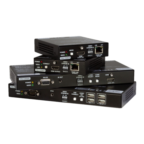
2. Product Overview VINX-1x0-HDMI Extenders – User's Manual Product Overview The following sections are about the physical structure of the device, input/ output ports, connectors, status LEDs and front panel button functions. ç VINX-120-HDMI-ENC ç VINX-110-HDMI-DEC ç VINX-120AP-HDMI-ENC ç VINX-120AP-HDMI-ENC-DNT ç VINX-210AP-HDMI-ENC ç... -
Page 13: Vinx-120-Hdmi-Enc
2. Product Overview VINX-1x0-HDMI Extenders – User's Manual 2.1. VINX-120-HDMI-ENC 2.2. VINX-110-HDMI-DEC Front and Rear View Front and Rear View 2 34 Status LEDs See the FrontPanelLEDs section. Status LEDs See theFrontPanelLEDssection. Mode Button Short press: switching between Video and Graphics modes. -
Page 14: Vinx-120Ap-Hdmi-Enc
2. Product Overview VINX-1x0-HDMIExtenders–User'sManual 2.3. VINX-120AP-HDMI-ENC Rear View Front View 5 6 7 Status LEDs See the FrontPanelLEDs section. Reset Button Reboots the device. RS-232 Port D-SUB9connectorfortransparentserialcommunication(point-to-point AV Input Ports RJ45connectorandslotforanSFPmodule.Oneatatimeisavailable or point-to-multi point). forreceivinganAVsignalAppliedcableshallbemax.100m(CAT5or CAT7) in case of RJ45. Please note that SFP module is not supplied IR Output Port IRsignaloutputconnector(for3.5mmJack,3-pole,TRSplug). -
Page 15: Vinx-120Ap-Hdmi-Enc-Dnt
2. Product Overview VINX-1x0-HDMIExtenders–User'sManual 2.4. VINX-120AP-HDMI-ENC-DNT Rear View Front View 6 7 8 Status LEDs See the FrontPanelLEDs section. Dante® Audio Output RJ45 connector for de-embedding the HDMI audio which can be transmitted as a 2-channel Dante® or AES67 source. Applied cable shall bemax.100m(CAT5orCAT7). -
Page 16: Vinx-210Ap-Hdmi-Enc
2. Product Overview VINX-1x0-HDMI Extenders – User's Manual 2.5. VINX-210AP-HDMI-ENC Rear View Front View 6 7 8 Status LEDs See the FrontPanelLEDs section. Reset Button Reboots the device. RS-232 Port D-SUB9connectorfortransparentserialcommunication(point-to-point AV Input Ports RJ45connectorandslotforanSFPmodule.Oneatatimeisavailable or point-to-multi point). forreceivinganAVsignal.Appliedcableshallbemax.100m(CAT5or... -
Page 17: Vinx-110Ap-Hdmi-Dec
2. Product Overview VINX-1x0-HDMI Extenders – User's Manual 2.6. VINX-110AP-HDMI-DEC Rear View Front View 4 5 6 Status LEDs See the FrontPanelLEDs section. Reset Button Reboots the device. RS-232 Port D-SUB9connectorfortransparentserialcommunication(point-to-point AV Input Ports RJ45connectorandslotforanSFPmodule.Oneatatimeisavailable or point-to-multi point). forreceivinganAVsignal.Appliedcableshallbemax.100m(CAT5or... -
Page 18: Front Panel Leds
2. Product Overview VINX-1x0-HDMI Extenders – User's Manual 2.7. Front Panel LEDs Dante® Audio Out LED state Left LED Right LED Function INFO: However,thecolorsoftheLEDsinthedevicesaredifferent,thefunctionsarethesame. POWER LED No power ▪ OFF: the device is not powered. ▪ BLINKING: booting is in progress. -
Page 19: Front Panel Buttons
2. Product Overview VINX-1x0-HDMIExtenders–User'sManual 2.9. Front Panel Buttons 2.10. DIP Switch TheDIPswitchcanbeusedtosettheVideoStreamIDmanually(HWsetting).TheinterpretationoftheDIP Audio Select Button #button AUDIO switch values can be found in the DIP Switch States section; please see the examples below: SELECT Toggle between the following modes: Video Stream ID /SYS/MB/GPIO. -
Page 20: Installation
3. Installation VINX-1x0-HDMI Extenders – User's Manual Installation The chapter is about the installation of the device and connecting to other appliances, presenting also the mounting options and further assembly steps. ç MountingOptions ç MountingintothePoweredRackmountCage ç ElectricalConnections ç... -
Page 21: Mounting Options
3. Installation VINX-1x0-HDMI Extenders – User's Manual 3.1. Mounting Options 3.1.2. Rack Shelf Mounting WARNING! For fixing the device to a Rack shelf, use the screw supplied with the extender. Longer screw WARNING! For fixing the device to a Rack shelf, use the screw supplied with the extender. Longer screw may touch internal parts and harm the device. -
Page 22: Ud-Kit Mounting
3. Installation VINX-1x0-HDMI Extenders – User's Manual 3.1.3. UD-kit Mounting 3.2. Mounting into the Powered Rackmount Cage WARNING! For fixing the device to a Rack shelf, use the screw supplied with the extender. Longer screw DIFFERENCE: Only the VINX-110-HDMI-ENC and VINX-120-HDMI-DEC devices are compatible with the may touch internal parts and harm the device. - Page 23 Step 3. Fastening the extender in the mounting slot. Place the extender (highlighted with grey) to the desired mounting slot and fasten the extender bracketwith1pcM4x8mmPH,DheadunpaintedscrewwithaPH1screwdriver.Payattentiontothe guide rails of the cage when placing the extender. Other Compatible Devices TherackmountcageiscompatiblewithotherLightwareextenders,too: HDMI-OPT-TX100 ▪ ▪ HDMI-OPT-TX100R ▪...
-
Page 24: Electrical Connections
3. Installation VINX-1x0-HDMIExtenders–User'sManual 3.3. Electrical Connections SFP Slots The module inserted in the SFP slot can be used for network connection (AV 1 GbE LAN and Dante® Audio Out transmission). Please note that SFP module is not supplied with the product. The... - Page 25 3. Installation VINX-1x0-HDMIExtenders–User'sManual Microphone Input Port (Return Audio) Mono input port for microphones including +20 dB gain in the signal path (compared to the forward audio signal level). If this input is connected to a powered equipment hum noise issue may occur. This case an isolation transformer (a passive DI box) can help.
-
Page 26: Connecting Steps
3. Installation VINX-1x0-HDMI Extenders – User's Manual 3.4. Connecting Steps ATTENTION! PleasemakesurethattheVINXdeviceswithinasystemrunthesamefirmware(package version).Ifthefirmwaresaredifferenttheseamlessworkingisnotguaranteed. 3.4.1. Preparing the Network ForthecorrectinstallationbuildaLocalAreaNetworkwithaLayer3(L3)typeswitch(highlyrecommended). However,UnicastmoderequiresonlyLayer2(L2)switch.InbothcasestheswitchmustsupporttheMulticast routing. ATTENTION! VINX Encoder and Decoder send certain system commands over multicast packages. If the multicast routing is disabled on the network, the signal transmission may fail. Layer 2 vs. -
Page 27: Point-To-Point Transmission (Unicast Mode)
3. Installation VINX-1x0-HDMI Extenders – User's Manual 3.4.3. Point-to-Point Transmission (Unicast Mode) 3.4.4. Installation Checkpoints The following help to have a successful install: Use CAT7 SFTP AWG23 cables for connecting the devices; the maximum allowed cable length is 100m. ▪... -
Page 28: Device Concept
4.DeviceConcept VINX-1x0-HDMI Extenders – User's Manual Device Concept The following chapter describes the features of the device with a few real-life examples. ç VINXDeviceConcept ç VideoInterface ç AnalogAudioInterface ç USBInterface ç Dante®AudioOutputInterface ç RS-232Interface Appliedfirmwarepackage:v2.0.2b4 | LDCsoftware:v2.5.2b3... -
Page 29: Vinx Device Concept
4.DeviceConcept VINX-1x0-HDMIExtenders–User'sManual 4.1. VINX Device Concept 4.2. Video Interface DIFFERENCE: The number of the Encoder and Decoder devices is 'limited' to 100 within a system with Thefollowingsectionsdescribethemodesofthevideotransmissions.Whenthenecessarynetworksettings firmwarepackagev1.x. are arranged, the following have to be set: The key feature of the VINX series is the AV signal transmission from an Encoder to many Decoder devices. -
Page 30: One-To-One Video Transmission (Unicast Mode)
4.DeviceConcept VINX-1x0-HDMI Extenders – User's Manual 4.2.1. One-to-one Video Transmission (Unicast Mode) 4.2.2. One-to-All Video Transmission (Multicast Mode) TheEncoderandtheDecoderdevicesarearrangedinaLANbyconnectingthemtoanL2 or L3 switch. Setting TheEncoderandDecoderdevicesarearrangedinaLANbyconnectingthemtoanL3 switch. Setting the the extenders to Unicast mode it is possible to extend the video signal by an Encoder to a dedicated Decoder. extenders to Multicast mode a certain video can be extended from an Encoder to multiple Decoders. -
Page 31: Layout Examples
4.DeviceConcept VINX-1x0-HDMI Extenders – User's Manual 4.2.3. Layout Examples Two Video Walls and Local Monitors with One Encoder The Layout Multicast Mode with Video Wall The Layout L3 Switch L3 Switch Features ▪ Two2x2-sizedvideowallsaredefinedandfurther2singledisplaysareinstalled(e.g.thevideowalls and the local displays are located in different rooms). ▪... -
Page 32: Analog Audio Interface
4.DeviceConcept VINX-1x0-HDMI Extenders – User's Manual 4.3. Analog Audio Interface Small View and Large View Combined in Multicast Mode The Layout DIFFERENCE: The analog audio option is available only in VINX AP-series. Unicast Mode The Layout L3 Switch Audio recoder Microphone... -
Page 33: Usb Interface
4.DeviceConcept VINX-1x0-HDMI Extenders – User's Manual 4.4. USB Interface 4.5. Dante® Audio Output Interface USB 1.1 and USB 2.0 data transmission operates between an Encoder and a certain Decoder device. Connect the DIFFERENCE: The following section refers to the VINX-120AP-HDMI-ENC-DNT model only. host device (e.g. - Page 34 4.DeviceConcept VINX-1x0-HDMIExtenders–User'sManual Important Notes Device Settings ▪ It is essential to have the right QoS settings in the network switch where the Dante® audio is connected The discovered Dante®-compatible devices are displayed with middle-blue color. Double-click on the name to open the device settings.
-
Page 35: Interface
4.DeviceConcept VINX-1x0-HDMIExtenders–User'sManual 4.6. RS-232 Interface Command Injection Mode DEFINITION: The Command Injection mode is like an RS-232–TCP/IP bidirectional converter. The mode Serial data transmission works between an Encoder and all the connected Decoders which have the same allowsdatatransmissionbetweenaTCP/IPdeviceandaserialdevice. -
Page 36: Software Control Options
Open a web browser (Google Chrome or Mozilla Firefox is highly recommended) and connect to the extender to access the parameters and settings. The other option is to use the Lightware Device Controller (LDC) software and connect to the device without a web browser. The features are described in the coming sections. -
Page 37: Software Control Modes
VINX-1x0-HDMI Extenders – User's Manual 5.1. Software Control Modes The VINX device can be controlled by the following ways: ▪ Using the built-in web page, ▪ Using the Lightware Device Controller (LDC) software, or Sending LW3 commands (detailed in the Programmer's ▪ Reference chapter). -
Page 38: Connecting Using Lightware Device Controller
LaunchtheLDCsoftware.TheEthernet tab consists of two lists: Oneoptionforcontrollingistousethewell-knownLDCsoftware.Downloaditfromwww.lightware.com install.Aftertheinstallation,theWindowsandthemacOSapplicationhasthesamelookandfunctionality. Favorite Devices: You can add any Lightware device that is connected via Ethernet and no need to ▪ This type of the installer is equal with the Normal install in case of Windows and results an updateable... -
Page 39: Connecting Via The Built-In Web Page
5.SoftwareControlOptions VINX-1x0-HDMIExtenders–User'sManual 5.3. Connecting via the Built-in Web Page Command Line Parameters The common way to start the software is double-click on ATTENTION! ThesupportedwebbrowsersareGoogleChromeandMozillaFirefox. theLDCiconbutyoucanusecommandlineparameters Another option for controlling the VINX device is to open the built-in web page. It is enough to connect to for special functions as follows. -
Page 40: Main Settings (Encoder)
5.SoftwareControlOptions VINX-1x0-HDMIExtenders–User'sManual 5.4. Main Settings (Encoder) 5.4.1. General Settings Unicast Mode #unicast The Video stream ID is used not only in Multicast mode. To assign an Encoder and a Decoder in Unicast mode, set the same Video stream ID in both devices. Grouping the VINX Extenders #multicast Video Stream ID... -
Page 41: Video Status And Settings
5.SoftwareControlOptions VINX-1x0-HDMIExtenders–User'sManual 5.4.2. Video Status and Settings Video Stream Bandwidth #bandwidth AspecificbandwidthlimitationcanbesetintheEncoderwhichaffects only the video signal transmission. The The properties of the incoming and outgoing video signals are displayed in the following sections. following values are available: Video Settings #hdcp Auto/10Mbps/50Mbps/100Mbps/150Mbps/200Mbps... -
Page 42: Main Settings (Decoder)
5.SoftwareControlOptions VINX-1x0-HDMIExtenders–User'sManual 5.5. Main Settings (Decoder) 5.5.2. Video Status and Settings The content of the window is almost the same as in the case of the Encoder. The Video Status Information 5.5.1. General Settings isfilledwithdetailswhenvalidsignalisdetectedandasinkisconnected.TheadditionistheScaler settings Unicast Mode #unicast which is also available on the Advanced Settings page. -
Page 43: Audio Settings
5.SoftwareControlOptions VINX-1x0-HDMIExtenders–User'sManual 5.5.3. Audio Settings No Signal Screen VINX decoders have a built-in screen which is sent to the output when there is no incoming signal on that Audio sink:youcanselectwheretotransmittheaudio,towardstheHDMIsinkand/ortheanalogaudiodevice particular decoder. It can be changed in this section to show a black screen. #new connected to the Decoder. -
Page 44: Crosspoint Menu
5.6.1. Frame Detector The ports can show detailed information about the signal like blanking intervals and active video resolution. Thisfeatureisagoodtroubleshooterifcompatibilityproblemsoccurduringsysteminstallation.Lightware’s Frame Detector function works like a signal analyzer and makes possible to determine the exact video format that is present on the port, thus helps to identify many problems. E.g. actual timing parameters may differ from the expected and this may cause some displays to drop the picture. -
Page 45: Multiviewer With Preview Images
5.SoftwareControlOptions VINX-1x0-HDMIExtenders–User'sManual 5.7. Multiviewer with Preview Images The preview image generated by an Encoder can be used to check the presence and the content of the active video signal of an Encoder. The image is updated in every third seconds approximately. The resolution oftheimageisonlyforpreview/thumbnailoption,therefore,itswidth is 360 pixels and the height is dynamic to maintain input aspect ratio. -
Page 46: Edid Menu
5.SoftwareControlOptions VINX-1x0-HDMIExtenders–User'sManual 5.8. EDID Menu 5.8.2. EDID Operations Changing the Emulated EDID DEFINITION: The Extended Display Identification Data (EDID) is the passport of the display devices. It contains Step 1. Choose the desired EDID list on the source panel and select an EDID. information about the capabilities of the display, such as supported resolutions and audio formats, refresh rates, the type and the manufacturer of the display device, etc. -
Page 47: Advanced Settings
5.SoftwareControlOptions VINX-1x0-HDMIExtenders–User'sManual 5.9. Advanced Settings 5.9.1. Common Settings (Encoder and Decoder) The submenu contains two tabs: Multicast and Unicast. The currently valid mode is highlighted with yellow. Press the desired button to choose the mode and access the settings. #unicast #multicast ATTENTION! Whenthemodeischangedthedevicemustberestarted;youwillgetanotification. -
Page 48: Decoder-Related Settings
5.SoftwareControlOptions VINX-1x0-HDMIExtenders–User'sManual 5.9.2. Decoder-related Settings OSD Settings (the On-Screen Display Feature) #osd Certainsystemmessagescanbedisplayedontheconnectedscreen;thefollowingaredefined: ▪ Enable OSD: set it to 'ON' state to enable the OSD feature. ▪ HDCP messages: 'HDCP failed' USB messages: 'Requesting USB', 'Starting USB', 'Stopping USB' ▪... -
Page 49: Lw3 Terminal
5.SoftwareControlOptions VINX-1x0-HDMIExtenders–User'sManual 5.9.3. LW3 Terminal ThiswindowisthesurfaceoftheLightwareProtocol3(LW3)treewithaterminalwindow.Commandsand specificparameters(whicharenotavailableonthegraphicaluserinterfaceoftheLDC)canberunandset. TheintroductionoftheLW3protocolandthemostimportantcommandscanbefoundintheProgrammer's Reference section. Legend #terminal LW3 Protocol Help Displaying the most important information about LW3 protocol commands in a new window. Terminal Window Commands and responses with time and date stamps are listed in this window. -
Page 50: Video Wall Setup
5.SoftwareControlOptions VINX-1x0-HDMIExtenders–User'sManual 5.10. Video Wall Setup 5.10.1. Creating a Video Wall Step 1. Navigate to the Video Wall Setup page. ATTENTION! This tab is displayed only when the device is in Multicast mode. Although changing Step 2. Press the New video wall button. Enter parameters usually takes effect within an acceptable period of time, it might happen that feedback is not the desired name of the wall (press received and not visible on the web page for several seconds. -
Page 51: Gap And Bezel Settings
5.SoftwareControlOptions VINX-1x0-HDMIExtenders–User'sManual 5.10.3. Gap and Bezel Settings Bezel Gap X ATTENTION! Always press the Apply changes button if you want to save the changes of the below Width mentioned parameters. DEFINITION: HerebydefinedGap means the physical distance between the edges of the display devices –seetheattachedfigure. -
Page 52: Programmer's Reference
6. Programmer's Reference VINX-1x0-HDMIExtenders–User'sManual Programmer' s Reference The device can be controlled through Lightware 3 (LW3) protocol commands to ensure the compatibility with other Lightware products. The supported LW3 commands are described in this chapter. ç VideoWallSetup ç Overview ç... -
Page 53: Overview
6. Programmer's Reference VINX-1x0-HDMIExtenders–User'sManual 6.1. Overview 6.3. Protocol Rules TheLightware Protocol #3(LW3) isimplementedinalmostallnewLightwaredevices(matrixswitchers, 6.3.1. The LW3 Tree Structure signal extenders and distribution amplifiers) since 2012.The protocol is ASCII-based and all commands / areterminatedwithacarriagereturn(Cr,‘\r’)andlinefeed(Lf,‘\n’)pair.Itisorganizedasatreestructure MEDIA thatprovidesoutstandingflexibilityanduser-friendlyhandlingwith‘nodes’,‘properties’and‘methods’.The... -
Page 54: Legend For The Control Commands
6. Programmer's Reference VINX-1x0-HDMIExtenders–User'sManual 6.3.3. Legend for the Control Commands 6.3.5. Command Types Command and Response – Example GET command ç GET•/SYS/MB/GPIO.DipSwitch The GETcommandcanbeusedtogetthechildnodes,propertiesandmethodsofaspecificnode.Itcanalso pr•/SYS/MB/GPIO.DipSwitch=<DIP_value> be used to get the value of a property. Use the dot character (.) when addressing a property: æ... -
Page 55: Prefix Summary
6. Programmer's Reference VINX-1x0-HDMIExtenders–User'sManual 6.3.6. Prefix Summary 6.3.9. Signature DEFINITION: Theprefixisa2-characterlongcodethatdescribesthetypeoftheresponse. DEFINITION: The signature is a four-digit-long hexadecimal value that can be optionally placed before every command to keep a command and the corresponding responses together as a group. ThefollowingprefixesaredefinedintheLW3protocol: Eachlineisterminatedwithacarriagereturn(Cr,‘\r’)andlinefeed(Lf,‘\n’)characters.Inseveralcasesthe... -
Page 56: Subscription
6. Programmer's Reference VINX-1x0-HDMIExtenders–User'sManual 6.3.10. Subscription 6.3.11. Notifications about the Changes of the Properties DEFINITION: Subscribetoanodemeansthattheuserwillgetanotificationifanyofthepropertiesofthe Whenthevalueofapropertyischangedandtheuserissubscribedtothenode,whichthepropertybelongs node is changed. to,anasynchronousnotificationisgenerated.Thisisnotificationiscalledasthe‘changemessage’.The format of such a message is very similar to the response for the GET command: Ausercansubscribetoanynode.Thesenotificationsareasynchronousmessagesandtheyareusefulto... -
Page 57: System Commands
The extender can be restarted; the current connections (RS-232, USB, etc...) will be terminated. ç GET/.ProductName Command and Response #reboot #restart #reset æ pr/.ProductName=VINX-120-HDMI-ENC ç CALL•/SYS:reset() 6.4.2. Setting the Device Label æ mO•/SYS:Reset Unique name can be set which will be visible when the given device is listed in the built-in web page of other Example VINX devices. -
Page 58: Network Configuration
6. Programmer's Reference VINX-1x0-HDMIExtenders–User'sManual 6.5. Network Configuration 6.5.3. Setting the IP Setup Mode (FW 2.x.x) DIFFERENCE: Thefollowingcommandisvalidwithfirmwarepackage2.x.x. ATTENTION! WhenyouchangeanetworkpropertythenewvalueisstoredbuttheapplySettings method mustbecalledalwaystoapplythenewsettings.Whentwoormoreserialparametersarechangedthe Command and Response applySettingsmethodisenoughtocallonceasafinalstep;itresultstheextendertoreboot. ç SET•/MANAGEMENT/NETWORK.IpSetupMode 6.5.1. Querying the IP Address pw•/MANAGEMENT/NETWORK.IpSetupMode=<IP_mode> æ Command and Response #network #ipsettings #dhcp Parameters ç... -
Page 59: Setting The Dhcp State (Fw 1.X.x)
6. Programmer's Reference VINX-1x0-HDMIExtenders–User'sManual 6.5.5. Setting the DHCP State (FW 1.x.x) 6.5.7. Querying the Subnet Mask DIFFERENCE: Thefollowingcommandisvalidwithfirmwarepackage1.x.x. Command and Response Command and Response ç GET•/MANAGEMENT/NETWORK.NetworkMask pr•/MANAGEMENT/NETWORK.NetworkMask=<subnet_mask> æ SET•/MANAGEMENT/NETWORK.DhcpEnabled=<DHCP_state> ç pw•/MANAGEMENT/NETWORK.DhcpEnabled=<DHCP_state> Example æ Parameters ç GET/MANAGEMENT/NETWORK.NetworkMask æ... -
Page 60: Setting A Static Gateway Address
6. Programmer's Reference VINX-1x0-HDMI Extenders – User's Manual 6.5.10. Setting a Static Gateway Address 6.6.3. Querying the Active Input Port DIFFERENCE: Make sure the IP address setting is static: DIFFERENCE: Below command is valid for VINX-210AP-HDMI-ENC device only. In case of FW 1.x.x: when the DhcpEnabled property is false you can set a static IP address. -
Page 61: Setting The Video Input Selection Mode
6. Programmer's Reference VINX-1x0-HDMI Extenders – User's Manual 6.6.5. Setting the Video Input Selection Mode 6.6.7. Setting the Video Quality Mode DIFFERENCE: Below command is valid for VINX-210AP-HDMI-ENC device only. The video quality mode can be set in the Encoder (see the previous section for details about the modes): Command and Response Command and Response SET•/MEDIA/VIDEO.SelectionMode=<sel_mode>... -
Page 62: Setting The Hdcp State
6. Programmer's Reference VINX-1x0-HDMI Extenders – User's Manual 6.6.9. Setting the HDCP State 6.7.2. Querying the Scaling Mode of the Output Video Signal HDCPcapabilitycanbeenabled/disabledontheinputportoftheEncoder,thus,non-encryptedcontentcan Command and Response #scaler be seen on a non-HDCP compliant display if the content allows it; see the HDCP Management section. -
Page 63: Setting The Resolution Of The Output Video Signal
6. Programmer's Reference VINX-1x0-HDMI Extenders – User's Manual 6.7.5. Setting the Resolution of the Output Video Signal 6.7.7. Setting the Signal Type of the Output Video Signal The resolution and the refresh rate of the outgoing video signal can be set. Command and Response Command and Response SET•/MEDIA/VIDEO/<out>/SCALER.SignalType=<sig_type>... -
Page 64: Audio-Related Commands
6. Programmer's Reference VINX-1x0-HDMIExtenders–User'sManual 6.8. Audio-related Commands 6.8.3. Querying the Audio Signal Presence Command and Response DIFFERENCE: The following commands refer to the AP-series only. ç GET•/MEDIA/AUDIO/<in>.SignalPresent The port numbering is a required parameter in most cases. See the details in the Audio Port Numbering section. - Page 65 6. Programmer's Reference VINX-1x0-HDMIExtenders–User'sManual 6.8.4.3. Setting the Volume (by a Step Value) 6.8.4.6. Setting the Volume (by a Step Value in Percantage) Command and Response Command and Response ç CALL•/MEDIA/AUDIO/<port>:stepVolumeDb(<value>) ç CALL•/MEDIA/AUDIO/<port>:stepVolumePercent(<value>) æ mO•/MEDIA/AUDIO/<port>:stepVolumeDb æ mO•/MEDIA/AUDIO/<port>:stepVolumePercent Parameters Parameters <value>...
-
Page 66: Serial Port Settings
6. Programmer's Reference VINX-1x0-HDMI Extenders – User's Manual 6.9. Serial Port Settings 6.9.3. Setting the RS-232 Port Mode The RS-232 port can be set to Pass-through or Command Injection mode. The introduction of these modes can ATTENTION! The new port settings are stored but applied only if the applySettings method is called which be found in the... -
Page 67: Setting The Stop Bits
6. Programmer's Reference VINX-1x0-HDMI Extenders – User's Manual 6.9.5. Setting the Stop Bits 6.10. Arranging the Extenders to Groups Command and Response 6.10.1. Querying the Working Mode (Unicast/Multicast) SET•/MEDIA/UART/<port>.StopBits=<Stopbits_value> ç Command and Response #unicast #multicast pw•/MEDIA/UART/<port>.StopBits=<Stopbits_value> æ... -
Page 68: Querying The Video Stream Id Setting Method
6. Programmer's Reference VINX-1x0-HDMI Extenders – User's Manual 6.10.3. Querying the Video Stream ID Setting Method 6.10.5. Querying the Video Stream ID The Video stream ID can be set by the front panel DIP switch or by software. The response of the below command contains the current Video Stream ID, but contains no information aboutthesettingmethod(HWsetting/SWsetting). -
Page 69: Video Wall Settings
6. Programmer's Reference VINX-1x0-HDMIExtenders–User'sManual 6.11. Video Wall Settings 6.11.2. Assigning a Decoder to a Video Wall ATTENTION! Setting the name of the video wall is highly recommended (see the previous section). Basic Rules #videowall Command and Response One Decoder can be a part of only one video wall. -
Page 70: Setting Up A Video Wall (Example)
6. Programmer's Reference VINX-1x0-HDMI Extenders – User's Manual 6.12. Setting up a Video Wall (Example) Commands Sent to the Decoder (A2) ç SET/MANAGEMENT/MULTICAST.MulticastMode=true ThefollowinglistofcommandsshowhowavideowallcanbecreatedbysendingLW3commands.The specificationsarethefollowing: æ pw/MANAGEMENT/MULTICAST.MulticastMode=true ▪ Office_2x2 Name: ç SET/SYS/MB/PHY.VideoChannelId=10 ▪ Size: æ pw/SYS/MB/PHY.VideoChannelId=10 192.168.0.81 192.168.0.82 ▪... -
Page 71: Crosspoint Switching Examples
6. Programmer's Reference VINX-1x0-HDMI Extenders – User's Manual 6.13. Crosspoint Switching Examples 6.13.4. Multiple Switching The commands have to be sent to the Decoders one-by-one thus, the switching ID: 1 ID: 2 ID: 3 ID: 4 The VINX devices can be arranged and used as a matrix. -
Page 72: Edid Management (Encoder)
6. Programmer's Reference VINX-1x0-HDMI Extenders – User's Manual 6.14. EDID Management (Encoder) 6.14.3. Copying an EDID Command and Response TheAdvancedEDIDManagementisavailablealsobysendingLW3protocolcommands.Thestructureofthe EDID memory can be found in the Multiviewer with Preview Images section. ç CALL•/EDID:copy(<source>:<destination>) 6.14.1. Querying the Emulated EDID æ... -
Page 73: Deleting An Edid From The User Memory
6. Programmer's Reference VINX-1x0-HDMI Extenders – User's Manual 6.14.5. Deleting an EDID from the User Memory Command and Response ç CALL•/EDID:delete(<User_loc>) æ mO•/EDID:delete Parameters Identifier Parameter description Parameter values <User_loc> User EDID location U1-U5 Example ç CALL/EDID:delete(U1) æ... -
Page 74: Lw3 Commands - Quick Summary
6. Programmer's Reference VINX-1x0-HDMIExtenders–User'sManual 6.15. LW3 Commands - Quick Summary System Commands Setting a Static Gateway Address SET•/MANAGEMENT/NETWORK.StaticGatewayAddress=<gateway_address> ç QueryingtheProductName Encoder-related Commands ç GET•/.ProductName SettingtheDeviceLabel QueryingtheInputVideoSignalPresence SET•/SYS/MB.DeviceLabel=<Custom_name> ç GET•/MEDIA/VIDEO/<in>.SignalPresent ç QueryingtheSerialNumber QueryingtheResolutionoftheInputVideoSignal ç GET•/.SerialNumber ç GET•/MEDIA/VIDEO/<in>.Resolution QueryingthePackageVersion QueryingtheActiveInputPort ç... - Page 75 6. Programmer's Reference VINX-1x0-HDMIExtenders–User'sManual Setting the No-signal-screen Serial Port Settings SET•/MEDIA/VIDEO/O1.EnableVinxGui=<vinx_gui> ç Setting the Port Availability Setting the Signal Type of the Output Video Signal SET•/MEDIA/UART/<port>.Enabled=<port_status> ç SET•/MEDIA/VIDEO/<out>/SCALER.SignalType=<sig_type> ç Setting the Baud Rate of the Port QueryingtheStateoftheUSBConnection SET•/MEDIA/UART/<port>.Baudrate=<Baud_value>...
- Page 76 6. Programmer's Reference VINX-1x0-HDMI Extenders – User's Manual Video Wall Settings SettingtheNameoftheVideoWall SET•/MEDIA/VIDEO/O1/VIDEOWALL.Name=<wall_name> ç AssigningaDecodertoaVideoWall SET•/MEDIA/VIDEO/O1/VIDEOWALL.Layout=<wall_parameters> ç EDID Management (Encoder) QueryingtheEmulatedEDID ç GET•/EDID.EdidStatus Setting the Emulated EDID on the Input Port ç CALL•/EDID:switch(<source>:<destination>) Copying an EDID ç...
-
Page 77: Firmware Upgrade
VINX-1x0-HDMI Extenders – User's Manual F irmware Upgrade The devices can be upgraded via the built-in web page or by the Lightware Device Updater v2 (LDU2) software. The software is available at www.lightware.com. In order to get the firmware pack with the necessary components (*.lfp or *.lfp2 file) for your specific product, please contact support@lightware.com. -
Page 78: Built-In Web Or Ldu2
Step 6. The progress bar and a short label will show the current state of the process. furtherfiles. ▪ Thereisadescriptorfileinthepackagethatcontainseachfirmwarewithversionnumberandalist showing the compatible devices which is displayed in Lightware Device Updater v2 (LDU2) after loading. 7.4. Option 1. – Upgrading via the Built-in Web Page WARNING! Never disconnect the power source from the VINX devices during the upgrade! Interrupting the firmware upgrade may cause the device unusable. -
Page 79: Option 2. - Upgrading By Ldu2
If you have a previously installed version you will be prompted to remove the old version before ▪ LDU2 software installed on your PC or Mac. installing the new one. Both can be downloaded from www.lightware.com/downloads. Installation in case of macOS Optionally, you can download the release notesfileinHTMLformat. MounttheDMGfilewithdoubleclickingonitanddragtheLDU2iconovertheApplicationsicontocopythe... -
Page 80: Running The Software
VINX-1x0-HDMI Extenders – User's Manual 7.6. Running the Software Main Screen Whenthesoftwareisstartedbytheshortcut,thedevicediscoveryscreenappears. You have two options: DISCOVER DEVICES Press the Discover devices buttontostartfindingtheLightwaredevices: ▪ Starting the LDU2bydouble-clickingontheshortcut/programfile,or ▪ Double-clicking on an LFP2 file. LDU2 Auto-Update At startup, the software checks if a newer version is available on the web. -
Page 81: The Upgrading Steps
Keeping the Configuration Settings Bydefault,deviceconfigurationsettingsarerestoredwhenfirmwareupgradeisfinished.Iffactoryresethas been chosen in the parameters window, all device settings will be erased. In the case of factory reset, you cansavethesettingsofthedeviceintheLightwareDeviceControllersoftwareandrestoreitlater. Thefollowingflowchartdemonstrateshowthisfunctionworksinthebackground. 1. Create a backup The current configuration of the device is being saved into a configuration backup file on your... - Page 82 7. Firmware Upgrade VINX-1x0-HDMI Extenders – User's Manual Step 1. Select the Firmware Package. Step 2. Select the desired devices for upgrading. Press the Choose Package File button and navigate to the location where Select the devices for upgrading; the selected line will be highlighted in green. CHOOSE PACKAGE FILE the...
-
Page 83: If The Upgrade Is Not Succesful
A root cause can be that the desired device is already in bootload (firmwareupgrade)mode,thus,thenormaloperationmodeissuspendedandbackupcannotbemade. If an upgrade is not succesful, the Export log button becomes red. If you press the button, you can ▪ downloadthelogfileasaZIPpackagewhichcanbesenttoLightwareSupportifneeded.Thelogfiles containusefulinformationaboutthecircumstancestofindtherootcause. #bootload Whentheprogressbarreaches100%(Doneisdisplayedatalldevices),theupgradeofalldevicesarefinished... -
Page 84: Troubleshooting
8. Troubleshooting VINX-1x0-HDMIExtenders–User'sManual T roubleshooting Usually, if the system seems not to transport the signal as expected, the best strategy for troubleshooting is to check signal integrity through the whole signal chain starting from source side and moving forward to receiver end. Pictogram Legend Linktothesectionofconnections/cabling. - Page 85 Connect it to the desired Decoder. ▪ The more of the above information you can give us the better. Please send these information to the is connected to LightwareSupportTeam(support@lightware.com) to speed up the troubleshooting process. another Decoder. USB data Another Decoder ChecktheLEDsortheUSBsettingsinthe...
-
Page 86: Technologies
9.Technologies VINX-1x0-HDMI Extenders – User's Manual Technologies The following sections contain descriptions and useful technical information how the devices work in the background. The content is based on experiences and cases we met in the practice. These sections help to understand features and technical standards like the following: ç... -
Page 87: Edid Management
After connecting a source to a display (DVI, HDMI, DP), the source reads out the EDID to determine the resolution and refresh rate of the image to be transmitted. Lightware devices provide the Advanced EDID Management function that helps system integration. The built-in EDID Router can store and emulate factory pre-programmed- and User programmable EDIDs. The Who are EDID of the attached monitors or projectors for each output are stored in a non-volatile memory. -
Page 88: Video Over Ip
9.Technologies VINX-1x0-HDMI Extenders – User's Manual 9.2. Video Over IP ToavoidunnecessaryHDCPencryption,LightwareintroducedtheHDCPenabling/disablingfunction:the HDCPcapabilitycanbedisabledintheLightwaredevice.IfHDCPisdisabled,theconnectedsourcewill Basics detect that the sink is not HDCP capable, and turn off authentication. Beside the traditional AV matrix switchers and extenders the video over IP or networked AV system is the 9.3.2. -
Page 89: Hdcp V2.2
HDCP v1.4 encryption. The signal is switched to an HDCP v2.2 compliant sink device. In this case the outgoing signal has to be encrypted with the highest supported encryption level towards the sink, as the Lightware device and the sink are both HDCP v2.2 compliant. The HDCP v2.2 standard does not allow keepingtheoriginalHDCPv1.4encryptionlevelontheoutput. -
Page 90: Signal Management (Vinx Ap-Series)
9.Technologies VINX-1x0-HDMIExtenders–User'sManual 9.4. RS-232 Signal Management (VINX AP-Series) 9.4.4. RS-232 Signal Transmission over VINX Devices ThefollowingexamplesshowwhensourceandsinkdevicesareconnectedoverLightware'sDCE-andDTE- 9.4.1. General Information type extenders for serial data transmission. There are two types of devices in general serial communication: Data Tranmission from a DCE Source to a DCE Sink Device Data Terminal Equipment: Data Terminal Equipment (DTE) is an end instrument that converts user ▪... -
Page 91: Appendix
10. Appendix VINX-1x0-HDMIExtenders–User'sManual Appendix Tables, drawings, guides, and technical details as follows: ç RS-232SignalManagement(VINXAP-Series) ç Specifications ç DelayintheVideoTransmission ç FactoryDefaultSettings ç DIPSwitchStates ç MechanicalDrawings ç OutputResolutions(Scaler) ç AudioPortNumbering ç FactoryEDIDList ç FirmwareReleaseNotes ç ApplicationNote(LW-AN-001) ç HashtagKeywordList ç... -
Page 92: Specifications
USB Port Type (Encoder) ........mini-B type receptacle 10.1.1. VINX Basic Series Connector type ........19-poleHDMItypeAreceptacle USB Port Type (Decoder) ........type-Areceptacle,4pcs. Valid for VINX-120-HDMI-ENC and VINX-110-HDMI-DEC devices. A/Vstandard .............. DVI1.0,HDMI1.4 ........... 2x USB 1.1 and 2x USB 2.0 compliant General HDCP Compliance ..............Yes, v2.2 Data Communication Mode ..........transparent... - Page 93 10. Appendix VINX-1x0-HDMIExtenders–User'sManual Power Video Input Audio formats ......EmbeddedLPCM,DolbyDigital5.1ch, Power supply option ......Poweradaptor(supplied)/PoE HDMI Input Port ....DolbyDigitalPlus,DolbyDigitalPro-Logic,DolbyTrueHD, Power over Ethernet (PoE) ......viaAVin/out(IEEE802.3af) Connector type ........19-poleHDMItypeAreceptacle ... DTS:X,DolbyAtmos,DTS5.1ch,DTS96/24,DTS-ESDiscrete, VINX-110AP-HDMI-DEC A/Vstandard .............. DVI1.0,HDMI1.4 DTS-ES Matrix, DTS-HD High Resolution Audio, DTS-HD Master Audio Powerconsumption(min/max) ........
-
Page 94: Delay In The Video Transmission
10. Appendix VINX-1x0-HDMIExtenders–User'sManual 10.2. Delay in the Video Transmission 10.3. Factory Default Settings Microphone Input (VINX-110AP-HDMI-DEC only) Gain in the signal path * ............... +20dB Due to the design of the devices frame delay is in the signal Parameter Setting/Value transmission from the Encoder towards the Decoder. -
Page 95: Mechanical Drawings
10. Appendix VINX-1x0-HDMIExtenders–User'sManual 10.5. Mechanical Drawings Thedimensionsareinmm.EncoderandDecoderdeviceshavethesamesizeofchassis.ThebasicVINXdevicesarebuiltintoquarter-racksizedchassis,theAP-serieshavehalf-racksizedchassis. Half-rack Sized Models Front View Bottom View 67.5 43.5 67.5 M3 thread Top View Quarter-rack Sized Models Top View Front View Bottom View VIDEO LINK ACT. POWER STREAM ID CONNECT 67.5 VIDEO... -
Page 96: Output Resolutions (Scaler)
10. Appendix VINX-1x0-HDMIExtenders–User'sManual 10.6. Output Resolutions (Scaler) 10.7. Audio Port Numbering Resolution Frame rate HEX identifier Resolution Frame rate HEX identifier 1366x768 81004048 VINX-210AP-HDMI-ENC 640x480 81004054 1440x900 81004021 Video port Audio port 640x480 80000001 1440x900 81004023 HDMI in 640x480 81004004... -
Page 97: Factory Edid List
10. Appendix VINX-1x0-HDMIExtenders–User'sManual 10.8. Factory EDID List Mem. Resolution Scan type EDID type Mem. Resolution Scan type EDID type 1920x 1080 @59.94 Hz 1920x 1080 @60.00 Hz Mem. Resolution Scan type EDID type 1920x 1080 @60.00 Hz 1920 x 1200 @ 59.56 Hz 640x... -
Page 98: Firmware Release Notes
Output standard is set to DVI. ▪ On a VINX-120-HDMI-ENC device, The EDID is not read from the Known issue: v1.2.1b1 sink connected to the local output of the encoder. Thus, it cannot ▪... - Page 99 10. Appendix VINX-1x0-HDMIExtenders–User'sManual ▪ Fixed a bug that casued the VINX encoder to restart when the Bugfix: v1.1.0b7 corresponding decoder was reading an EDID from the attached ▪ Fixed a bug that caused the video not to be transmitted properly Releasedate:2018-05-31 device that had a Video Format Preference block in its CEA in Unicast mode when switching Video Stream ID on the encoder.
-
Page 100: Application Note (Lw-An-001)
(AV) and information technology (IT) worlds, Lightware suggests involvement of both AV and IT departments in any installation. Lightware products are designed to be plug-and-play.The figures in the next section illustrate the basic installation of one Decoder and one Encoder. A video source provides the digital video content to the... - Page 101 10. Appendix VINX-1x0-HDMI Extenders – User's Manual Switch Setup for Dante® Audio Signal Transmission a specific multicast content via subscribing to the multicast group devices in the subnet to receive such control information, multicast corresponding to the content. Using IGMPv2 packets, the end-point filteringmustbesetup,sothatunregisteredgroupsareforwardedto...
-
Page 102: Hashtag Keyword List
#dhcp #multicast Multicast mode setting This keyword is placed at the DHCP (dynamic IP address) setting in #mute Mute/unmute(foranalogaudio)setting thefrontpaneloperation,theLightwareDeviceController(LDC)and #network Network (IP address) related settings theLW3programmer'sreferencesection. Newfeature/functionoftheproduct The following list contains all hashtag keywords placed in the document with a short description belonging to them. The list is in... -
Page 103: Further Information
Black-screen option added; FW Laszlo apre-agreedfigure. 2.2 01-02-2021 upgrade chapter upgraded; minor Zsedenyi 3. All products to be returned to Lightware require a return material corrections. authorizationnumber(RMA)priortoshipmentandthisnumbermust Multiviewer description added; minor Laszlo 2.3 12-03-2021 be clearly marked on the box. If an RMA number is not obtained or is corrections.
Need help?
Do you have a question about the VINX-120-HDMI-ENC and is the answer not in the manual?
Questions and answers