Table of Contents
Advertisement
Quick Links
Advertisement
Table of Contents

Related Manuals for Lightware UMX-TP-TX100R


Summary of Contents for Lightware UMX-TP-TX100R
- Page 1 UMX-TP-TX100R Programmer’s Reference Manual...
-
Page 3: Safety Instructions
UMX-TP-TX100R Programmer’s Reference Manual SAFETY INSTRUCTIONS Class II apparatus construction. This equipment should be operated only from the power source indicated on the product. To disconnect the equipment safely from power, remove the power cord from the rear of the equipment, or from the power source. The MAINS plug is used as the disconnect device, the disconnect device shall remain readily operable. -
Page 4: Declaration Of Conformity
DECLARATION OF CONFORMITY Lightware Kft. 15 Peterdy Street, Budapest H-1071, HUNGARY as manufacturer declare, that the product UMX-TP-TX100R ( Computer Monitor Extender ) in accordance with the EMC Directive 2004/108/EC and the Low Voltage Directive 2006/95/EEC is in conformity with the following standards: EMI/EMC ........ -
Page 5: Table Of Contents
UMX-TP-TX100R Programmer’s Reference Manual Table of contents ELECTRICAL CONNECTIONS ........................ 7 1.1. HDMI I ............................7 NPUT 1.2. VGA I ............................7 NPUT 1.3......................8 IGITAL AUDIO INPUT CONNECTOR 1.4..................8 NALOG STEREO AUDIO INPUT CONNECTORS 1.5........................9... - Page 6 4.7........................27 ORT STATUS COMMANDS 4.7.1. Input port status ........................27 4.7.2. Output port status ........................27 4.7.3. All port status ........................... 27 4.8..........................28 NPUT PROPERTIES 4.8.1. Set input port properties ......................28 4.8.2. Query input port properties ...................... 30 4.8.3.
-
Page 7: Electrical Connections
UMX-TP-TX100R Programmer’s Reference Manual 1. Electrical connections 1.1. HDMI Input UMX-TP-TX100R provides standard 19 pole HDMI connector for inputs. Always use high quality HDMI cable for connecting sources and displays. HDMI Type A receptacle Signal Signal TMDS Data2+ TMDS Clock Shield TMDS Data2 Shield TMDS Clock–... -
Page 8: Digital Audio Input Connector
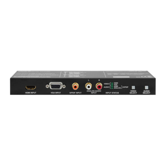
Plugs and sockets on consumer equipment are conventionally color-coded by CEA/CEDIA-863-B (ANSI) to aid correct connections. According to the standard Lightware uses red colored RCA connectors for right channel of analog stereo audio signals and white colored RCA connectors for left channel of analog stereo audio signals. -
Page 9: Twisted Pair Outputs
Table 1-5. RJ45 input and output connector pin assignment Warning: Avoid interchanging the connection to the VIDEO and DDC lines! Wiring of RJ45 plugs Lightware recommends the termination of TP cables on the basis of TIA/EIA T 568 A or TIA/EIA T 568 B standards. TIA/EIA color and... -
Page 10: Rs-232 Control Port
1.6. RS-232 control port UMX-TP-TX100R can be remote controlled through industry standard 9 pole D-SUB female connector. The extender uses RS 232 control port. Figure 1-2. D-SUB 9 pole female connector (DE9F) Pin nr. RS-232 NC - non connected TX data transmit (output) -
Page 11: About Edid Memory
UMX-TP-TX100R Programmer’s Reference Manual 2. About EDID memory EDID memory is non-volatile and consists of four blocks, each for different purpose. These blocks are: Factory preset EDIDs User saved EDIDs Dynamic EDID (EDID of last connected sink on the DDC output port) ... -
Page 12: Factory Edid List
CAT cable). DSUB connector TP connector Pin 2: DSUB TX OUT Pin 6: TP RX IN Pin 3: DSUB RX IN Pin 3: TP TX OUT Figure 3-1. UMX-TP-TX100R in CONTROL mode Page 12 / 43 Section 3. Operation modes... - Page 13 For more information see section 4.4.5 on page 18. Info: UMX-TP-TX100R stores the RS232 working mode and starts the saved one after reboot. The default baud rate for control is 57600, the command to set the baud rate can be the following: {RS232BAUD=9600}...
-
Page 14: Programmers Reference
4. Programmers reference Users can connect to the extender through serial port. Lightware UMX-TP-TX100R can be controlled with external devices which can communicate according to the extender protocol. 4.1. Serial port settings UMX-TP-TX100R uses RS-232 communication port. D-SUB connector pin assignments can be found in section on page 10. -
Page 15: Status And Identification Commands
→ {i} Command {I} ← (I:UMX-TP-TX100R)CrLf Response (<PRODUCT_TYPE>)CrLf Legend: <PRODUCT_TYPE> shows the router model. Explanation: The connected device is an UMX-TP-TX100R. 4.3.2. View serial number Description: The extender responds its 8-digit serial number. Format Example → {s} Command {S} ← (SN:10170142)CrLf Response (<SERIAL_NUMBER>)CrLf... -
Page 16: View Cpu Firmware Compile Time
Slot 0 represents the motherboard. <MB_DESC> The motherboard description contains the name and the version number. Explanation: The extender reports that it has one motherboard called UMX-TP-TX100R and its version number is SCH_1.2. 4.4. System commands 4.4.1. Query current control protocol Description: Shows the RS-232 control protocol. -
Page 17: Change Rs-232 Baud Rate
UMX-TP-TX100R Programmer’s Reference Manual 4.4.2. Change RS-232 baud rate Description: The RS-232 baud rate can be set. The command has to be sent with the earlier baud rate but the response comes with the new baud rate. Format Example → {RS232BAUD=9600} Command {RS232BAUD=<rate>}... -
Page 18: Set The Rs232 Operation Mode
Explanation: Factory default settings reloaded for crosspoint and I/O card configurations and emulated EDIDs. Info: The response may contain additional messages as the router makes the configurations. These responses can be omitted. Info: After resetting the needed parameters, the device restarts. 4.4.5. -
Page 19: Restart Matrix Router
Command {RST} Response (Booting…)CrLf ← (Booting…)CrLf ← (<name>●Ready!)CrLf (UMX-TP-TX100R Ready!) Legend: <name> is the type of the extender Explanation: The extender reboots and sends a message when it is ready. Info: The response can be seen only if the connection to the extender is still alive. -
Page 20: Configure Remote Alerts
4.4.11. Configure remote alerts Description: The device logs different levels of errors. Configure which level of errors has to be sent out as an alarm message. Format Example → {ELEVELSEND#1=0,0,1,1,1} {ELEVELSEND#<p>= Command <0>,<1>,<2>,<3>,<4>} ← (ELEVELSEND#1=0,0,1,1,1)CrLf Response (ELEVELSEND#<p>= <0>,<1>,<2>,<3>,<4>)CrLf Explanation: The device will send an immediate message on all control interfaces when a ‘matter’, ‘error’... -
Page 21: Query The Priority Settings
UMX-TP-TX100R Programmer’s Reference Manual 4.4.14. Query the priority settings Description: This command queries the video priority mode. Format Example → {videopriority=?} Command {VIDEOPRIORITY=?} Response (VIDEOPRIORITY=<pmode>)CrLf ← (VIDEOPRIORITY=1)CrLf Legend: Please read section 4.4.13 on page 20. Explanation: The device uses HDMI priority in the autoselect mode. -
Page 22: Watch Edid Validity Table
4.5.3. Watch EDID validity table Description: Shows EDID validity table, which contains information about the EDID memory states. Format Example → {wv*} Command {WV<type>} Response (EV<type>● ← (EVU 31111111)CrLf ← <VALIDITY_TABLE>)CrLf (EVD 1)CrLf ← (EVE 11)CrLf Legend: <type> <name> Response length Factory preset EDIDs User saved EDIDs Dynamic EDID... -
Page 23: Download Edid Content From The Router
UMX-TP-TX100R Programmer’s Reference Manual 4.5.5. Download EDID content from the router Description: EDID hex bytes can be read directly. The router will issue the whole content of the EDID present on memory location <loc> (256 bytes). Format Example → {wef1} Command {WE<loc>}... -
Page 24: Delete Edid From Memory
4.5.7. Delete EDID from memory Description: Clear EDID from memory location <loc>. Format Example → {deu3} Command {DE<loc>} ← Response (E_SW_OK)CrLf (E_SW_OK) ← (DE_OK)CrLf (DE_OK)CrLf ← (E_S_C)CrLf (E_S_C)CrLf Legend: Depending on <loc>, one EDID, or all EDIDs in a block can be cleared. <loc>... -
Page 25: Switch One Input To One Output
Info: If the command is used without the <A/V/AV> parameter, both layers are switched. Info: UMX-TP-TX100R does not support disconnecting command. {0@<out>} 4.6.2. View video connection on the output Description: This command shows the video connection status of the output. -
Page 26: Rename An Input
Renaming Inputs / Output Description: Allows storing names for each input / output. Any 16-byte long string is allowed (16 characters). All characters are converted to uppercase! 4.6.4. Rename an input Format Example → {iname#2=Media Player} Command {INAME#<id>=<input_name>} Response (INAME#<id>=<input_name>)CrLf ← (INAME#2=MEDIA PLAYER)CrLf Legend: <id>... -
Page 27: Reload Default Output Name
UMX-TP-TX100R Programmer’s Reference Manual 4.6.9. Reload default output name Format Example → {oname#1=!} Command {ONAME#<id>=!} Response (ONAME#<id>=Output●<id>)CrLf ← (ONAME#1=Output 1)CrLf Legend: <id> must be 1. Explanation: The output name is set to default: “Output 1”. 4.7. Port status commands 4.7.1. Input port status Description: Shows the actual status of the input ports. -
Page 28: Input Properties
4.8. Input properties The following commands are setting up the properties of the input ports. If only one or a few parameters have to be modified, the protocol enables to mask the other parameters, so they can stay untouched. To mask a parameter use “x” or “X” as its value. Example: {:ANALOG#2@SI=x;x;x;x;210;x;} Only change the horizontal position on the input port 2. - Page 29 UMX-TP-TX100R Programmer’s Reference Manual Source dependent parameters: Analog signal properties are displayed, when <SOURCE> = R / C: <ATIM1> Analog timing1: 0 = SMTPE standard 1 = User saved preset 2 = EDID detailed timing 3 = Factory preset 4 = GTF formula 5 = User modified (not saved) <ATIM2>...
-
Page 30: Query Input Port Properties
0x0B 0x0C 0x0D 0x0E 0x0F 0x10 0x11 0x12 0x13 0x14 0x15 0x16 0x17 0x18 0x19 0x1A 0x1B 0x1C 0x1D 0x1E 0x1F Where: Front Left Front Center Front Right Front Left Center Front Right Center Rear Left Rear Center Rear Right Rear Left Center Rear Right Center Subwoofer... -
Page 31: Set Analog Timing Properties
UMX-TP-TX100R Programmer’s Reference Manual 4.8.3. Set analog timing properties Description: This command changes the setup of the analog timing data. Format Example → {:analog#2@si= Command {:ANALOG#<in>@<S/A>I= <PHS>;<FHS>; 10;2160; <HS>;<VS>; 1600;1200; <HP>;<VP>;} 455;41;} ← (ANALOG#2@SI= Response (DVII#<in>@<S/A>I= <PHS><FHS>; 10;2160; <HS>;<VS>; 1600;1200;... -
Page 32: Set Analog Color Properties
4.8.6. Set analog color properties Description: Set analog color properties data of the input ports. Format Example → {:picture#2@si= Command {:PICTURE#<in>@<S/A>I= <DF_CHA>;<DF_CHB>;<DF_CHC>; 1023;1023;1023; <G_CHA>;<G_CHB>;<G_CHC>; 1023;1023;1023; <O_CHA>;<O_CHB>;<O_CHC>; 1023;1023;1023; <CONT>;<SAT>;<BRIGHT>;<HUE>;) 128;128;0;0;)CrLf ← (PICTURE#2@SI= Response (PICTURE#<in>@<S/A>I= <DF_CHA>;<DF_CHB>;<DF_CHC>; 1023;1023;1023; <G_CHA>;<G_CHB>;<G_CHC>; 1023;1023;1023; <O_CHA>;<O_CHB>;<O_CHC>; 1023;1023;1023; <CONT>;<SAT>;<BRIGHT>;<HUE>;)CrLf 128;128;0;0;)CrLf Legend: <S/A>:... -
Page 33: Query Analog Color Properties
UMX-TP-TX100R Programmer’s Reference Manual 4.8.8. Query analog color properties Description: Check analog color properties data of the input ports. Format Example → {:picture#2@si=?} Command {:PICTURE#<in>@<S/A>I=?} ← (PICTURE#2@SI= Response (PICTURE#<in>@<S/A>I= <DF_CHA>;<DF_CHB>;<DF_CHC>; 1023;1023;1023; <G_CHA>;<G_CHB>;<G_CHC>; 1023;1023;1023; <O_CHA>;<O_CHB>;<O_CHC>; 1023;1023;1023; <CONT>;<SAT>;<BRIGHT>;<HUE>;)CrLf 128;128;0;0;)CrLf Legend: Please read section 4.8.6... -
Page 34: Query Analog Input Audio Properties
4.8.11. Query analog input audio properties Description: This command reads the setup of the ADC on the audio board. Format Example → {:audin#2@si=?} Command {:AUDIN#<in>@<S/A>I=?} ← (AUDIN#2@SI=0;50;0;0;0;)CrLf Response (:AUDIN#<in>@<S/A>I=<VOL>; <BAL>;<GAIN>;<PHS>;<DCF>)CrLf Legend: Please read section 4.8.10 on page 33. 4.8.12. Set the color of no sync picture Description: If there is no incoming video signal the device gives a monochrome 640x480p60 picture to the output. -
Page 35: Query Timings Of The Incoming Signal
UMX-TP-TX100R Programmer’s Reference Manual 4.8.14. Query timings of the incoming signal Description: This command reads out the properties of the incoming signal on the selected input ports. Format Example → {:GETTIMINGS#1@SI=?} Command {GETTIMINGS#<in>@<S/A>=?} ← (GETTIMINGS#1@SI= Response (GETTIMINGS#<in>@<S/A>= <TLW>; 2200; <LW>;... -
Page 36: Delete All Presets
4.8.17. Delete all presets Description: This command deletes all the presets from the analog input port. Format Example → {:af#2@si=DEL;255} Command {:AF#<in>@SI=DEL;255} ← (AF DELETED)CrLf Response (AF DELETED)CrLf Explanation: The command deletes all the presets. 4.8.18. Clone preset Description: This command clones the desired preset to all of the input ports. Format Example →... -
Page 37: Delete Preset From All Input Ports
UMX-TP-TX100R Programmer’s Reference Manual 4.8.20. Delete preset from all input ports Description: This command deletes the desired from all analog input ports. Format Example → {:af#2@si=delall;1} Command {:AF#<in>@SI=DELALL;<PID>} ← (AF DELETED)CrLf Response (AF DELETED)CrLf Legend: <PID> Preset ID number Explanation: This command is reserved for compatibility reasons. - Page 38 <MODE>: Output signal mode D = DVI, H = HDMI 24bit, 1 = HDMI 30bit deepcolor 2 = HDMI 36bit deepcolor <SIG>: Signal present 0 = No valid signal is routed to this port, 1 = Valid video signal is present. <HDCP>: HDCP encryption status 0 = HDCP encryption is inactive,...
-
Page 39: Query Output Video Properties
UMX-TP-TX100R Programmer’s Reference Manual 4.9.2. Query output video properties Description: Displays the status for output port. Format Example → Command {:HDMI#<out>@<S/A>O=?} {:hdmi#1@so=?} ← Response (HDMI#<out>@<S/A>O= (HDMI#1@SO= G<CON><MODE><SIG> G1H111; <HDCP><HPD>; OAAAAA; O<MODE><CSPAC> M100111070;)CrLf <CRANG>;<SUBS> <HDCP>) M<HSUP><AUTH><REP> <YUV4><YUV2> <AUD><PCM><DC>CrLf Legend: Please read section 4.9.1... -
Page 40: Commands - Quick Summary
5. Commands – Quick summary Router Status commands Section Command View product type 4.3.1 View serial number 4.3.2 View Firmware version of the CPU 4.3.3 View installed controllers’ firmware 4.3.4 {FC} View device’s temperature 4.3.5 {ST} View CPU firmware compile time 4.3.6 {CT} View installed I/O boards... - Page 41 UMX-TP-TX100R Programmer’s Reference Manual Input settings Section Command Set input port properties 4.8.1 {:DVII#<in>@<S/A>I=<VIDEO>; <X1>;<X2>;<HDCP>} Query input port properties 4.8.2 {:DVII#<in>@<S/A>I=?} Set analog timing properties 4.8.3 {:ANALOG#<in>@<S/A>I=<PHS> ;<FHS>;<HS>;<VS>;<HP>;<VP>;} Query analog timing properties 4.8.4 {:ANALOG#<in>@<S/A>I=?} Reset analog timing properties 4.8.5 {:ANALOG#<in>@<S/A>I=...
- Page 42 Control commands Section Command Switch one input to one output 4.6.1 {<in>@<out>●<A/V/AV>} View video connection on the output 4.6.2 {?<out>} View all connections on the output 4.6.3 {VC●<A/V/AV>} Rename an input 4.6.4 {INAME#<id>=<input_name>} Rename the output 4.6.5 {ONAME#<id>=<output_name>} Read an input’s name 4.6.6 {INAME#<in>=?} Read the output’s name...
-
Page 43: Version Applicability
The customer shall pay shipping charges when unit is returned for repair. Lightware will cover shipping charges for return shipments to customers. In case of defect please call your local representative, or Lightware at Lightware Visual Engineering 15 Peterdy Street, Budapest H-1071, HUNGARY Tel.:...
Need help?
Do you have a question about the UMX-TP-TX100R and is the answer not in the manual?
Questions and answers