Table of Contents
Advertisement
Quick Links
Download this manual
See also:
User Manual
Advertisement
Table of Contents

Related Manuals for Lightware UMX-TPS-TX100 Series


Summary of Contents for Lightware UMX-TPS-TX100 Series
- Page 1 User’s Manual UMX-TPS-TX120, -TX130, -TX140 WP-UMX-TPS-TX120-US Black, White WP-UMX-TPS-TX130-US Black, White FP-UMX-TPS-TX130-MKM HDBaseT Multimedia Extender...
- Page 2 UMX-TPS-TX100 series – User's Manual Important Safety Instructions Waste Electrical & Electronic Equipment Common Safety Symbols WEEE Class II apparatus construction. Symbol Description This marking shown on the product or its literature, The equipment should be operated only from the power source indicates that it should not be disposed with other indicated on the product.
- Page 3 The following symbols and markings are used in the document: This User’s Manual applies to the following versions of the mentioned Lightware Visual Engineering supports green technologies and software, firmware, and hardware: eco-friend mentality. Thus, this document is made for digital usage...
-
Page 4: Table Of Contents
2.4. Connecting Steps ...............13 3.15.2. Transmitter Cloning – Configuration Backup and Restore ..26 5.6.3. Test Pattern ..................38 2.4.1. WP-UMX-TPS-TX100 series ............13 3.15.3. Remote Firmware Upgrade of Connected Lightware Devices ... 26 5.7. EDID Menu ...................39 2.4.2. UMX-TPS-TX100 series ..............13 5.7.1. EDID Operations................39 4. OPERATION ..................27 2.5. Powering Options ...............14... - Page 5 UMX-TPS-TX100 series – User's Manual Table of Contents 5.12. Advanced View Window ............50 7.4.11. Lock an Input Port ................ 66 7. LW3 PROGRAMMERS’ REFERENCE ..........58 7.4.12. Unlock an Input Port ..............66 7.1. Overview ..................58 6. LW2 PROGRAMMER'S REFERENCE ..........51 7.4.13. Mute Output ..................
- Page 6 8.4.2. Start the LDU and Follow the Instructions ........84 7.6.7. Query the Gateway Address ............73 8.5. Keeping the Configuration Settings .........87 7.6.8. Change the Gateway Address (Static) .......... 74 8.6. Remote Firmware Upgrade of Connected Lightware Devices ...88 7.7. RS-232 Port Configuration ............74 9. TROUBLESHOOTING ................89 7.7.1. Protocol Setting ................74 7.7.2. BAUD Rate Setting ................
-
Page 7: Introduction
Management forces the required resolution from any video source Number The device can and fixes the output format conforming to the system requirements. Thank You for choosing Lightware’s UMX-TPS-TX100 series device. In the first HDBaseT be mounted into The unit offers bi-directional and transparent IR, RS-232 and Ethernet... -
Page 8: Box Contents
1. Introduction UMX-TPS-TX100 series – User's Manual 1.4. Box Contents 1.5. Features WP-UMX-TPS-TX100 series UMX-TPS-TX100 series 3D and 4K Support High bandwidth allows extension of resolutions up to 4K and even 3D sources and displays are supported. Signal Transmission up to 170 m... -
Page 9: Model Comparison
1. Introduction UMX-TPS-TX100 series – User's Manual 1.6. Model Comparison Breakaway Audio/Video Switching Breakaway audio/video switching allows for switching The available models have different features depending on their design. The following table contains the most important differences between the models: audio and video separately by de-embedding and embedding audio from/into HDMI signals. -
Page 10: Typical Application
1. Introduction UMX-TPS-TX100 series – User's Manual 1.7. Typical Application Standalone Application Diagram - WP-UMX-TPS-TX130-US Standalone Application Diagram - UMX-TPS-TX140 12V DC power adaptor analog audio Blu-ray player IR emitter IR detector 12V DC RS-232 power adaptor... -
Page 11: Installation
2.1. Mounting Options - UMX-TPS-TX100 series INFO: The chipboard screws are not supplied with the mounting kit. To mount the transmitter Lightware supplies optional accessories for 2.1.2. 1U High Rack Shelf different usage. There are two kinds of mounting kits with similar Allows rack mounting for half-rack, quarter-rack and pocket sized fixing method. -
Page 12: Mounting Options - Wp-Umx-Tps-Tx100 Series
2. Installation UMX-TPS-TX100 series – User's Manual 2.2. Mounting Options - WP-UMX-TPS-TX100 series 2.3. Mounting Options - FP-UMX-TPS-TX130-MKM Step 2. Move the handles towards the frame. Align the tab on the assembly with the slot in the frame. -
Page 13: Connecting Steps
2. Installation UMX-TPS-TX100 series – User's Manual 2.4. Connecting Steps 2.4.2. UMX-TPS-TX100 series VGA laptop HDMI laptop MacBook Media player 2.4.1. WP-UMX-TPS-TX100 series VGA laptop HDMI laptop MacBook Audio HDMI Audio Audio HDMI UMX-TPS-TX100 series CATx transmitter Audio1 HDCP... -
Page 14: Powering Options
2. Installation UMX-TPS-TX100 series – User's Manual 2.5. Powering Options Power MX-FR17 send CATx TPS-PI-1P1 (TPS) External CATx power supply (TPS) 48V DC Power Power send adaptor 48V DC Power adaptor MX-FR17 2 IN LIVE Power 2 IN... -
Page 15: Product Overview
3. Product Overview UMX-TPS-TX100 series – User's Manual 3.1. Front View - UMX-TPS-TX100 series UMX-TPS-TX120 6 8 9 UMX-TPS-TX130 P roduct Overview 6 8 9 The following sections are about the physical structure of the device, input/... -
Page 16: Rear View - Umx-Tps-Tx100 Series
Ethernet Locking RJ-45 connector for configuring the device using Lightware Device device. Controller (LDC), or upgrading it using Lightware Device Updater (LDU). Any third- VGA input D-SUB connector for analog video signal. party control system can use this port to control the device. -
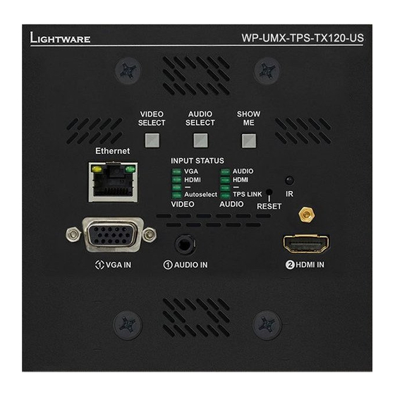
Page 17: Rear View - Wp-Umx-Tps-Tx100 Series
Extension Distances section. device using Lightware Device Controller (LDC), (PoE) transmission. Maximum CATx cable distances or upgrading it using Lightware Device Updater 48V DC input Power the device remotely by a PoE- can be found in the Maximum Extension (LDU). Any third-party control system can use compatible power injector (TPS-PI-1P1). -
Page 18: Electrical Connections
Locking DC connector Interface section. UMX-TPS-TX100 series transmitters are built with locking 12V DC 3.7.8. Analog Stereo Audio (Phoenix) connector. Do not forget to turn the plug clockwise direction before 5-pole Phoenix connector is used for balanced analog disconnecting the power adaptor. -
Page 19: Ethernet Connector (Tps And Lan Ports)
INFO: The maximum total current for the seven GPIO pins is 180 mA. Wiring of TPS and LAN Cables 3.7.11. IR Connector Level and Lightware recommends the termination of LAN cables on the basis of IR detector and IR emitter can be connected to the Pin nr. direction TIA/EIA T 568 A or TIA/EIA T 568 B standards. -
Page 20: Tps Extender Concept
INFO: WP-UMX-TPS-TX130-US and FP-UMX-TPS-TX130-MKM models have the same functionality, the only difference in the size of the enclosure. The UMX-TPS-TX100 series transmitters and wallplates are universal audio/video extenders with analog/ 3.9. TPS Interface digital conversion and audio embedding functions. The devices receive analog (VGA, DVI-A) and digital (DP,... -
Page 21: Port Diagram
3. Product Overview UMX-TPS-TX100 series – User's Manual 3.10. Port Diagram The following figure describes the port diagram of the UMX-TPS-TX140 transmitter. The principle of the operation is the same for all models. Analog video VGA in... -
Page 22: Video Interface
Remains selected Laptop VGA IN Port with Port with priority Priorities can be set in Lightware Device Controller software, see related settings in the TPS Video Output priority 1 has a 1 is selected valid signal? and the TPS Audio Output sections. -
Page 23: Audio Interface
3. Product Overview UMX-TPS-TX100 series – User's Manual 3.13. Audio Interface 3.13.2. Audio Options - Example 3.13.1. Audio Input Modes ANALOG AUDIO IN 2 The device can receive embedded digital audio signal on the HDMI, DisplayPort, and DVI-D input ports and analog audio signal on the Jack and the Phoenix input ports. -
Page 24: Control Features
3. Product Overview UMX-TPS-TX100 series – User's Manual 3.14. Control Features Control Mode The incoming data from the given port is processed and interpreted by the CPU. The mode allows to control 3.14.1. Serial Interface the transmitter directly. LW2 or LW3 protocol commands are accepted – depending on the current port Technical Background setting. -
Page 25: Ir Interface
An IR detector is attached to the Infrared input port of the TPS receiver and IR signals are sent by the Remote IR in TCP / IR controller. The TPS Receiver is connected to an UMX-TPS-TX100 series transmitter built with IR output port converter port via TPS line. -
Page 26: Gpio Interface
SELECT SELECT The firmware of the Lightware TPS devices can be upgraded individually by Lightware Device Updater (LDU) ATTENTION! Please always check the electrical parameters of the devices what you want to control. The software. UMX-TPS-TX100 series transmitters and wallplates contain a feature which allows having a faster maximum current of one GPIO pin is 30 mA, the maximum total current for the seven pins is 180 mA. -
Page 27: Operation
4. Operation UMX-TPS-TX100 series – User's Manual 4.1. Front Panel LEDs 4.1.3. Autoselect LED INFO: WP-UMX-TPS-TX130-US and FP-UMX-TPS-TX130-MKM models have the same functionality. The operation of the status Audio1 HDCP RESET HDMI HDMI Autoselect DVI-A Video DVI-D DVI-D Audio2 LEDs is also similar. -
Page 28: Tps Link Led
4. Operation UMX-TPS-TX100 series – User's Manual 4.1.5. TPS LINK LED 4.2. Rear Panel LEDs 4.2.4. LINK LED OFF: 4.2.1. LIVE LED PIN: 2.1mm W W P P - - U U M M X X - - T T P P S S - - T T X X 1 1 3 3 0 0 - - U U S S... -
Page 29: Front Panel Buttons
4. Operation UMX-TPS-TX100 series – User's Manual 4.3. Front Panel Buttons 4.3.2. Audio Select Button 4.3.4. Programmable Show Me Button INFO: WP-UMX-TPS-TX130-US and FP-UMX-TPS-TX130-MKM Audio1 HDCP RESET Audio1 HDCP RESET models have the same functionality. The operation of the front... -
Page 30: Reset To Factory Default Settings
W W P P - - U U M M X X - - T T P P S S - - T T X X 1 1 3 3 0 0 - - U U S S buttons Show Me together ▪ Lightware Device Controller (LDC) - you can connect to the device (within 100 ms) to disable/ via our control software using Ethernet or RS-232 interface and enable front panel buttons; VIDEO... -
Page 31: Software Control - Lightware Device Controller
The device can be controlled by a computer through the Ethernet and RS-232 Normal install Snapshot install ports using Lightware Device Controller (LDC). The software can be installed The common way to start the software is double-click on the LDC Available for Windows and macOS Available for Windows on a Windows PC or macOS. -
Page 32: Connecting To A Device (Device Discovery Window)
LW3 protocol are set on the serial port. The Ethernet tab consists of two lists: Favorite Devices: You can add any Lightware device that is connected via Ethernet and no need to ▪ browse all the available devices. Devices can be added by pressing the Add button or marking the desired device by the symbol in the All Devices list. -
Page 33: Crosspoint Menu
5. Software Control - Lightware Device Controller UMX-TPS-TX100 series – User's Manual 5.4. Crosspoint Menu Port Tiles The colors of the port tiles and the displayed icons represent different states and information: Port name Port icon LINKOUT... -
Page 34: Port Properties Windows
5. Software Control - Lightware Device Controller UMX-TPS-TX100 series – User's Manual 5.5. Port Properties Windows 5.5.2. Digital Video Inputs Available settings: ▪ Mute/unmute the port; Clicking on the HDMI, DisplayPort, or DVI-D input port icon results Clicking on the port tile opens the Port properties window. This section Lock/unlock the port;... -
Page 35: Analog Audio Inputs
5. Software Control - Lightware Device Controller UMX-TPS-TX100 series – User's Manual 5.5.3. Analog Audio Inputs 5.5.4. Digital Audio Inputs 5.5.5. TPS Video Output Click on the output port to display its properties. The most important information and settings are available from the panel. -
Page 36: Tps Audio Output
5. Software Control - Lightware Device Controller UMX-TPS-TX100 series – User's Manual 5.5.6. TPS Audio Output Available settings: ▪ Mute/unmute the port; Certain parameters of the digital audio output signal can be set as Lock/unlock the port;... -
Page 37: Diagnostic Tools
5. Software Control - Lightware Device Controller UMX-TPS-TX100 series – User's Manual 5.6. Diagnostic Tools Table and Chart Views Cable diagnostics can be displayed in advanced modes as well. Two ways are available: table view and chart 5.6.1. Cable Diagnostics... -
Page 38: Frame Detector
Frame detector window Color: Click on the desired color or use the sliders and press Lightware’s Frame Detector function works like a signal analyzer and the Set color button to store. makes possible to determine the exact video format that is present on the port, thus helps to identify many problems. -
Page 39: Edid Menu
5. Software Control - Lightware Device Controller UMX-TPS-TX100 series – User's Manual 5.7. EDID Menu 5.7.1. EDID Operations Advanced EDID Management can be accessed by selecting the EDID menu. There are two panels: left one Changing Emulated EDID contains Source EDIDs, right one contains Destination places where the EDIDs can be emulated or copied. -
Page 40: Edid Summary Window
5. Software Control - Lightware Device Controller UMX-TPS-TX100 series – User's Manual 5.7.2. EDID Summary Window 5.7.3. Editing an EDID Info Select an EDID from Source panel and press Info button to display EDID summary. Select an EDID from Source panel and press Edit button to display Advanced EDID Editor Edit window. -
Page 41: Creating An Edid - Easy Edid Creator
5.8.1. RS-232 Create Lightware introduced a wizard-like interface for fast and easy EDID creation. With Easy EDID Creator it is possible to create custom EDIDs in four simple steps. By clicking on the Create button below Source panel, Easy EDID Creator is opened in a new window. -
Page 42: Gpio
5. Software Control - Lightware Device Controller UMX-TPS-TX100 series – User's Manual 5.8.2. GPIO 5.8.3. Ethernet GPIO tab in Control menu Ethernet tab in Control menu The GPIO port has 7 pins, which operate at TTL digital signal levels and can be controlled by LDC or protocol Two ports are displayed in the Ethernet settings: Local, CPU, and TPS. -
Page 43: Infra
5. Software Control - Lightware Device Controller UMX-TPS-TX100 series – User's Manual 5.8.4. Infra Description Function ATTENTION! The device has no built-in Infrared receiver and transmitter. For the complete usage attach Code number. an IR emitter unit to the IR OUT and an IR detector unit to the IR IN connectors. -
Page 44: Event Manager
5. Software Control - Lightware Device Controller UMX-TPS-TX100 series – User's Manual 5.9. Event Manager Ports User can set the name and command injection port to each sources and destinations. For more details The feature means that the device can sense changes on its ports and able to react... -
Page 45: The Event Editor
5. Software Control - Lightware Device Controller UMX-TPS-TX100 series – User's Manual 5.9.1. The Event Editor 5.9.2. Create or Modify an Event Press the Edit button in the desired Event line to open the Event editor window. Wizard Mode The wizard mode lists the most common conditions and actions, so the user does not have to look for LW3 nodes and properties. -
Page 46: Special Tools And Accessories
5. Software Control - Lightware Device Controller UMX-TPS-TX100 series – User's Manual 5.9.3. Special Tools and Accessories 5.9.6. Event Creating - Example no delay Condition = true Perform the action The following example shows you on a real-life situation how to set The Name of the Event up an Event. -
Page 47: Settings Menu
5. Software Control - Lightware Device Controller UMX-TPS-TX100 series – User's Manual 5.10. Settings Menu Setting the Event You can create the Event in the Wizard in few simple 5.10.1. Status steps: Step 1. Set the condition. Select the required parameters to set the condition: ▪... -
Page 48: Network
5. Software Control - Lightware Device Controller UMX-TPS-TX100 series – User's Manual 5.10.2. Network 5.10.4. Front Panel Network tab in Settings menu Front panel operation LEDs and buttons can be configure in this tab. IP address and DHCP settings can be set on this tab. Always press the Apply settings button to save changes. -
Page 49: System
Backup tab System tab in Settings menu Configuration cloning of Lightware LW3 devices is a simple method that eliminates the need to repeatedly Three functions are available under System tab: configure certain devices to have identical (non-factory) settings. If the devices are installed in the same ▪... -
Page 50: Save The Settings Of A Device (Backup)
5. Software Control - Lightware Device Controller UMX-TPS-TX100 series – User's Manual 5.11.2. Save the Settings of a Device (Backup) 5.12. Advanced View Window Step 1. Apply the desired settings in the transmitter (port parameters, crosspoint, etc.) Step 2. Select the Settings / Backup tab from the menu. -
Page 51: Lw2 Programmer's Reference
The device can be controlled through a reduced command set of LW2 protocol <id> id number in 1 or 2 digit ASCII format commands to ensure the compatibility with other Lightware products. The supported LW2 commands are described in this chapter. <id²>... -
Page 52: View Firmware Version Of The Cpu
6. LW2 Programmer's Reference UMX-TPS-TX100 series – User's Manual 6.2.3. View Firmware Version of the CPU 6.2.8. View Firmware for All Controllers Description: View the CPU firmware revision. Description: Shows the firmware versions of all installed controllers. Format... -
Page 53: A/V Port Settings
6. LW2 Programmer's Reference UMX-TPS-TX100 series – User's Manual 6.3. A/V Port Settings 6.3.3. Unmute Output Description: Unmute output <out>. 6.3.1. Switch an Input to the Output Following commands with <A/V/AV> option can take effect in multiple layers, according to their parameters. -
Page 54: View Connection State On The Output
6. LW2 Programmer's Reference UMX-TPS-TX100 series – User's Manual 6.3.6. View Connection State on the Output 6.3.8. Change Video Autoselect Mode Description: Viewing the crosspoint state of the device; showing the input port numbers connected to the Description: The autoselect mode of the video outputs can be changed. -
Page 55: Change The Video Input Priorities
6. LW2 Programmer's Reference UMX-TPS-TX100 series – User's Manual 6.3.10. Change the Video Input Priorities 6.4. Network Configuration Description: The settings of video input priority can be changed as follows. 6.4.1. Query the Current IP Status Format Example Description: IP address settings can be queried as follows. -
Page 56: Set The Gateway Address
6. LW2 Programmer's Reference UMX-TPS-TX100 series – User's Manual 6.4.4. Set the Gateway Address Description: Gateway address can be set as follows. Format Example Command {IP_GATEWAY=<gateway_addr>} {ip_gateway=192.168.0.50} Response (IP_GATEWAY=<gateway_addr>)CrLf (IP_GATEWAY=192.168.0.50) Legend: <gateway_addr>: Four decimal octets separated by dots. -
Page 57: Lw2 Commands - Quick Summary
6. LW2 Programmer's Reference UMX-TPS-TX100 series – User's Manual 6.6. LW2 Commands – Quick Summary Network Configuration See in General LW2 Commands Operation Command section See in Operation Command Query the Current IP Status 6.4.1 {IP_STAT=?} section Set the IP Address 6.4.2... -
Page 58: Lw3 Programmers' Reference
(Cr, ‘\r’) and line feed (Lf, ‘\n’) pair. It is organized as a tree structure that provides outstanding flexibility and user-friendly handling with ‘nodes’, ‘properties’ and ‘methods’. The Advanced View of the Lightware Device Controller software is the perfect tool for browsing and learning how the LW3 protocol can be used in practice. -
Page 59: Command Types
7. LW3 Programmers’ Reference UMX-TPS-TX100 series – User's Manual 7.2.3. Command Types 7.2.4. Prefix Summary DEFINITION: The prefix is a 2-character long code that describes the type of the response. GET command The following prefixes are defined in the LW3 protocol: The GET command can be used to get the child nodes, properties and methods of a specific node. -
Page 60: Signature
7. LW3 Programmers’ Reference UMX-TPS-TX100 series – User's Manual 7.2.7. Signature 7.2.9. Notifications about the Changes of the Properties DEFINITION: The signature is a four-digit-long hexadecimal value that can be optionally placed before When the value of a property is changed and the user is subscribed to the node, which the property belongs every command to keep a command and the corresponding responses together as a group. -
Page 61: System Commands
7. LW3 Programmers’ Reference UMX-TPS-TX100 series – User's Manual 7.3. System Commands 7.3.4. Query the Firmware Version 7.3.1. Query the Product Name Command and Response Î GET·/SYS/MB.FirmwareVersion The name of the product is a read-only parameter and cannot be modified. -
Page 62: Lock The Front Panel Buttons
7. LW3 Programmers’ Reference UMX-TPS-TX100 series – User's Manual 7.3.7. Lock the Front Panel Buttons 7.3.9. Dark Mode This command turns LEDs off the on the transmitter. Command and Response Î SET /MANAGEMENT/UI.ControlLock=<lock_status> Command and Response Í pw /MANAGEMENT/UI.ControlLock=<lock_status>... -
Page 63: Video Port Settings
7. LW3 Programmers’ Reference UMX-TPS-TX100 series – User's Manual 7.4. Video Port Settings The Most Common Received Port Status Responses INFO: Video port numbering can be found in the Port Numbering section. 7.4.1. Query the Status of Source Ports... -
Page 64: Query The Status Of Destination Port
7. LW3 Programmers’ Reference UMX-TPS-TX100 series – User's Manual 7.4.2. Query the Status of Destination Port 7.4.4. Switching Video Input Command and Response Command and Response Î GET·/MEDIA/VIDEO/XP.DestinationPortStatus Î CALL·/MEDIA/VIDEO/XP:switch(<in>:<out>) pr·/MEDIA/VIDEO/XP.DestinationPortStatus=<out1_state>;<out2_state>;<…>;<out#_state> Í mO·/MEDIA/VIDEO/XP:switch Í Parameters Example <out#_state> The response contains 5 ASCII characters for each port. The first character indicates the Î... -
Page 65: Change The Autoselect Mode
7. LW3 Programmers’ Reference UMX-TPS-TX100 series – User's Manual 7.4.6. Change the Autoselect Mode 7.4.8. Change the Input Port Priority Command and Response Command and Response Î CALL·/MEDIA/VIDEO/XP:setAutoselectionPriority (<in>\(<out>\):<prio>);(<in>\(<out>\):<prio>) Î CALL·/MEDIA/VIDEO/XP:setDestinationPortAutoselect(<out1_set>;<out2_set>;<…>;<out#_set>) Í mO·/MEDIA/VIDEO/XP:setAutoselectionPrioirty Í mO·/MEDIA/VIDEO/XP.setDestinationPortAutoselect Parameters Parameters <prio>... -
Page 66: Lock An Input Port
7. LW3 Programmers’ Reference UMX-TPS-TX100 series – User's Manual 7.4.11. Lock an Input Port 7.4.15. Lock Output Command and Response Command and Response Î CALL·/MEDIA/VIDEO/XP:lockSource(<in>) Î CALL·/MEDIA/VIDEO/XP:lockDestination(<out>) Í mO·/MEDIA/VIDEO/XP:lockSource Í mO·/MEDIA/VIDEO/XP:lockDestination Example Example Î CALL /MEDIA/VIDEO/XP:lockSource(I1) Î CALL /MEDIA/VIDEO/XP:lockDestination(O1) Í... -
Page 67: Test Pattern Generator Mode
7. LW3 Programmers’ Reference UMX-TPS-TX100 series – User's Manual 7.4.18. Test Pattern Generator Mode 7.4.20. Test Pattern Color The output port can send a special image towards the sink device for testing purposes. The setting is Command and Response available on the input ports with the below-listed parameters. -
Page 68: Color Space Setting (Output Port)
7. LW3 Programmers’ Reference UMX-TPS-TX100 series – User's Manual 7.4.23. Color Space Setting (Output Port) Command and Response SET·/MEDIA/VIDEO/<out>.ColorSpaceSetting=<colorspace> Î pw·/MEDIA/VIDEO/<out>.ColorSpaceSetting=<colorspace> Í Parameters <colorspace> Color space Auto YCbCr 4:4:4 YCbCr 4:2:2 Example Î SET /MEDIA/VIDEO/O1.ColorSpaceSetting=2 Í pw /MEDIA/VIDEO/O1.ColorSpaceSetting=2 7.4.24. Query the Recent TPS Mode... -
Page 69: Audio Port Settings
7. LW3 Programmers’ Reference UMX-TPS-TX100 series – User's Manual 7.5. Audio Port Settings The Most Common Received Port Status Responses INFO: Audio port numbering can be found in the Port Numbering section. 7.5.1. Query the Status of Source Ports... -
Page 70: Query The Audio Crosspoint Setting
7. LW3 Programmers’ Reference UMX-TPS-TX100 series – User's Manual 7.5.3. Query the Audio Crosspoint Setting Example Î GET /MEDIA/AUDIO/XP.DestinationPortAutoselect Command and Response Í pr /MEDIA/AUDIO/XP.DestinationPortAutoselect=EL Î GET·/MEDIA/AUDIO/XP.DestinationConnectionList EL: the Autoselect is Enabled on output, selected mode is Last detect. -
Page 71: Query The Input Port Priority
7. LW3 Programmers’ Reference UMX-TPS-TX100 series – User's Manual 7.5.7. Query the Input Port Priority 7.5.9. Mute an Audio Input Command and Response Command and Response Î GET·/MEDIA/AUDIO/XP.PortPriorityList Î CALL·/MEDIA/AUDIO/XP:muteSource(<in>) Í pr·/MEDIA/AUDIO/XP.PortPrioirtyList= <out1_list>;<out2_list>;<…>;<out#_list> Í mO·/MEDIA/AUDIO/XP:muteSource The response shows the priority of each output one after another. The priority number can be from 0 to 31;... -
Page 72: Mute Audio Output
7. LW3 Programmers’ Reference UMX-TPS-TX100 series – User's Manual 7.5.13. Mute Audio Output 7.5.17. Analog Audio Input Level Settings 7.5.17.1. Volume Command and Response Î CALL·/MEDIA/AUDIO/XP:muteDestination(<out>) Command and Response Í mO·/MEDIA/AUDIO/XP:muteDestination SET·/MEDIA/AUDIO/<In>.Volume=<level> Î pw·/MEDIA/AUDIO/<In>.Volume=<level> Í Example Î CALL /MEDIA/AUDIO/XP:muteDestination(O1) Parameters Í... -
Page 73: Network Configuration
7. LW3 Programmers’ Reference UMX-TPS-TX100 series – User's Manual 7.6. Network Configuration 7.6.4. Change the IP Address (Static) 7.6.1. Query the DHCP State Command and Response SET·/MANAGEMENT/NETWORK.StaticIpAddress=<IP_address> Î Command and Response pw·/MANAGEMENT/NETWORK.StaticIpAddress=<IP_address> Í Î GET·/MANAGEMENT/NETWORK.DhcpEnabled pw·/MANAGEMENT/NETWORK.DhcpEnabled=<dhcp_status> Example Í Î SET /MANAGEMENT/NETWORK.StaticIpAddress=192.168.0.85 Parameters Í... -
Page 74: Change The Gateway Address (Static)
7. LW3 Programmers’ Reference UMX-TPS-TX100 series – User's Manual 7.6.8. Change the Gateway Address (Static) 7.7.3. Databit Setting Command and Response Command and Response SET·/MANAGEMENT/NETWORK.StaticGatewayAddress=<gw_address> Î SET·/MEDIA/UART/<serial_port>.DataBits=8|9 Î pw·/MANAGEMENT/NETWORK.StaticGatewayAddress=<gw_address> Í pw·/MEDIA/UART/<serial_port>.DataBits=8|9 Í Example Example Î SET /MEDIA/UART/P1.DataBits=8 Î SET /MANAGEMENT/NETWORK.StaticGatewayAddress=192.168.0.5 Í... -
Page 75: Operation Mode
7. LW3 Programmers’ Reference UMX-TPS-TX100 series – User's Manual 7.7.6. RS-232 Operation Mode 7.8. Infrared Port Configuration Command and Response INFO: Infrared input and output port numbering can be found in the Port Numbering section. SET·/MEDIA/UART/<serial_port>.Rs232Mode=<serial_mode> 7.8.1. Enable Command Injection Mode Î... -
Page 76: Sending Message Via The Communication Ports
7. LW3 Programmers’ Reference UMX-TPS-TX100 series – User's Manual 7.9. Sending Message via the Communication Ports Sending a TCP Binary Message (HEX-format) The command is for sending a binary message in Hexadecimal format. This method does not allow escaping 7.9.1. Sending Message via TCP Port... -
Page 77: Message Sending Via Rs-232 Serial Port
7. LW3 Programmers’ Reference UMX-TPS-TX100 series – User's Manual Sending a TCP Text (ASCII-format) Sending a Text (ASCII-format) The command is for sending a text message in ASCII-format via UDP-protocol. This method does not allow The command is for sending a command message in ASCII-format. This method does not allow escaping the escaping or inserting control characters. -
Page 78: Gpio Port Configuration
7. LW3 Programmers’ Reference UMX-TPS-TX100 series – User's Manual 7.10. GPIO Port Configuration 7.10.3. Toggle the Level of a GPIO Pin INFO: Use the GET command to query a parameter. Command and Response 7.10.1. Set the Direction of a GPIO Pin Î... -
Page 79: Query The Preferred Resolution Of An User Edid
7. LW3 Programmers’ Reference UMX-TPS-TX100 series – User's Manual 7.11.3. Query the Preferred Resolution of an User EDID 7.11.6. Copy an EDID to User Memory Command and Response Command and Response Î GET·/EDID/U/<user_edid>.PreferredResolution Î CALL·/EDID:copy(<source>:<destination>) pr·/EDID/U/<user_edid>.PreferredResolution=<preferred_resolution> Í mO·/EDID:copy Í... -
Page 80: Lw3 Commands - Quick Summary
7. LW3 Programmers’ Reference UMX-TPS-TX100 series – User's Manual 7.12. LW3 Commands - Quick Summary System Commands Query the Product Name Query the Video Autoselect Settings Î GET·/.ProductName Î GET·/MEDIA/VIDEO/XP.DestinationPortAutoselect Set the Device Label Change the Autoselect Mode SET·/MANAGEMENT/UID.DeviceLabel=<Custom_name>... - Page 81 7. LW3 Programmers’ Reference UMX-TPS-TX100 series – User's Manual Test Pattern Resolution Mute an Audio Input SET·/MEDIA/VIDEO/<In>.FreeRunResolution=<freerun_resolution> Î CALL·/MEDIA/AUDIO/XP:muteSource(<in>) Î Test Pattern Color Unmute an Audio Input SET·/MEDIA/VIDEO/<in>.FreeRunColor=<RGB_code> Î CALL·/MEDIA/AUDIO/XP:unmuteSource(<in>) Î HDCP Setting (Output Port) Lock an Input Port SET·/MEDIA/VIDEO/<On>.HdcpModeSetting=<hdcp_mode>...
- Page 82 7. LW3 Programmers’ Reference UMX-TPS-TX100 series – User's Manual Change the Subnet Mask (Static) UDP Message Sending via Ethernet SET·/MANAGEMENT/NETWORK.StaticNetworkMask=<netmask> Î CALL·/MEDIA/ETHERNET:udpMessage(<IP_address>:<port_no>=<message>) Î Î CALL•/MEDIA/ETHERNET:udpText(<IP_address>:<port_no>=<text>) Query the Gateway Address Î CALL•/MEDIA/ETHERNET:udpBinary(<IP_address>:<port_no>=<HEX_message>) Î GET·/MANAGEMENT/NETWORK.GatewayAddress Message Sending via RS-232 Serial Port Change the Gateway Address (Static) Î...
-
Page 83: Firmware Upgrade
Î Install and Upgrade 8.2. Short Instructions Î Detailed Instructions Î Step 1. Get the firmware pack and the Lightware Device Updater (LDU) Keeping the Configuration Settings Î application. Remote Firmware Upgrade of Connected Lightware Devices Î Step 2. Install the LDU application. -
Page 84: Detailed Instructions
8. Firmware Upgrade UMX-TPS-TX100 series – User's Manual Step 2. Set the desired update settings in the Options section. Step 1. Select the package. ▪ If you do not want to check for the updates automatically, Click on the Browse button and select the “.lfp”... - Page 85 8. Firmware Upgrade UMX-TPS-TX100 series – User's Manual Step 2. Select device. Firmware Components The firmware components of the selected devices are listed on the following screen: installed and update versions. (Update version will be uploaded to the device.) The following step is to select the desired device(s).
- Page 86 8. Firmware Upgrade UMX-TPS-TX100 series – User's Manual Step 3. Upgrade the device. When you confirmed the warnings, the upgrade process starts automatically. Click on the Start button to continue. Details button opens a new window where the process is logged – see below.
-
Page 87: Keeping The Configuration Settings
Repeat button starts the process again with the selected device(s). Instructions page in the UMX-TPS-TX100 series firmware package Open logs button opens the temporary folder where the logs can be found. ATTENTION! In specific cases restoring cannot be applied fully and certain settings are not copied back Export logs by saving the files as a zipped file. -
Page 88: Remote Firmware Upgrade Of Connected Lightware Devices
Firmware of Lightware devices can be upgraded via another connected Lightware device without removing the device from the system. It means user does not have to connect directly to the upgradable device, it can be reached and flashed through other devices. It’s a more comfortable way to keep up-to-date your Lightware devices. -
Page 89: Troubleshooting
9. Troubleshooting UMX-TPS-TX100 series – User's Manual At first, check front panel LEDs and take the necessary steps according to their states. For more information about status, LEDs refer to Front Panel LEDs Rear Panel LEDs sections. - Page 90 9. Troubleshooting UMX-TPS-TX100 series – User's Manual Symptom Root cause Action Refer to Symptom Root cause Action Refer to Audio signal GPIO No audio is Source audio volume is Check the audio settings of the source.
-
Page 91: Technologies
(dynamic EDID emulation). information about additional Detailed Timings, audio capabilities, For example, the Lightware device can be set up to emulate a sink speaker allocation and HDMI capabilities. It is important to know that device, which is connected to one of the outputs. -
Page 92: Hdcp Management
To avoid unnecessary HDCP encryption, Lightware introduced the HDCP enabling/disabling function: the HDCP capability can be disabled in the Lightware device. If HDCP is disabled, the connected source will detect that the sink is not HDCP capable, and turn off authentication. -
Page 93: Pixel Accurate Reclocking
10. Technologies UMX-TPS-TX100 series – User's Manual 10.3. Pixel Accurate Reclocking Jitter Signal instability in the time domain. The time difference between two Signal reclocking is an essential important procedure in digital signal signal transitions should be a fixed value, but noise and other effects transmission. -
Page 94: Appendix
11. Appendix UMX-TPS-TX100 series – User's Manual 11.1. Specification Enclosure (UMX-TPS-TX100 series) Rack mountable .................Yes General Material .................. 1 mm steel Compliance ..................CE Dimensions in mm ..........221W x 100.4D x 26H EMC compliance (emission) ......... EN 55032:2015 Dimensions in inch ........... - Page 95 11. Appendix UMX-TPS-TX100 series – User's Manual HDMI Input Reclocking ............ Pixel Accurate Reclocking Volume................-95.62 – 0 dB HDMI port connector type ....19-pole HDMI Type A receptacle 3D support ..................Yes Maximum input level ....... +4 dBu, 1.23 Vrms, 3.47 Vpp Standard ..............
-
Page 96: Factory Default Settings
11. Appendix UMX-TPS-TX100 series – User's Manual 11.2. Factory Default Settings 11.3. Content of Backup File The backup file contains numerous settings and parameters saved Parameter Setting/Value Parameter Setting/Value from the device. When the file is uploaded to a device, the followings... -
Page 97: Audio Cable Wiring Guide
Symmetric audio is most often referred to as balanced audio, as opposed to asymmetric, which is referred to as unbalanced audio. Lightware products are usually built with 5-pole Phoenix connectors so we would like to help users assembling their own audio cables. -
Page 98: Mechanical Drawings
11. Appendix UMX-TPS-TX100 series – User's Manual 11.5. Mechanical Drawings Top View 11.5.1. UMX-TPS-TX100 series UMX-TPS-TX140 UMX-TPS-TX140 can be seen in the pictures, but the dimensions are the same for all the three models. Universal TPS Transmitter Rear LED functions Port legend Dimensions are in mm. -
Page 99: Wp-Umx-Tps-Tx100 Series
11. Appendix UMX-TPS-TX100 series – User's Manual 11.5.2. WP-UMX-TPS-TX100 series 11.5.3. FP-UMX-TPS-TX130-MKM WP-UMX-TPS-TX130-US can be seen in the pictures, but the dimensions are the same for both models. Dimensions are in mm. Dimensions are in mm. Front View Front View Ø7.5 90°/Ø... -
Page 100: Port Numbering
11. Appendix UMX-TPS-TX100 series – User's Manual 11.6. Port Numbering 11.6.3. UMX-TPS-TX120 11.6.1. WP-UMX-TPS-TX120-US Audio/Video Ports Video port nr. (LW3) Audio port nr. (LW3) Audio/Video Ports Emulated Video port Audio port Port name EDID Till fw From fw Till fw From fw nr. -
Page 101: Umx-Tps-Tx140
11. Appendix UMX-TPS-TX100 series – User's Manual 11.6.5. UMX-TPS-TX140 11.6.6. FP-UMX-TPS-TX130 Audio/Video Ports Audio/Video Ports Emulated Video port nr. (LW3) Audio port nr. (LW3) Emulated Video port Video port Audio port Audio port Video port Audio port Port name... -
Page 102: Factory Edid List
11. Appendix UMX-TPS-TX100 series – User's Manual 11.8. Factory EDID List Mem. Resolution Type Mem. Resolution Type 1364 x 768 @ 50.00 Reserved Mem. Resolution Type Mem. Resolution Type 1364 x 768 @ 59.94 2560 x 1600 @ 59.86... -
Page 103: Further Information
Zsedenyi 1.4. Product failures from six (6) months to the end of the warranty photo replaced period will either be repaired or replaced at the discretion of Lightware. Minor updates for LDC v1.8.0 and Tamas If Lightware chooses to replace the product then the replacement will 10-06-2016 LDU v1.3.0, updated Event Manager,...
Need help?
Do you have a question about the UMX-TPS-TX100 Series and is the answer not in the manual?
Questions and answers