Lightware UBEX-PRO20-HDMI-F110 User Manual
Av over ip multimedia extender
Hide thumbs
Also See for UBEX-PRO20-HDMI-F110:
- User manual (201 pages) ,
- User manual (253 pages) ,
- User manual (185 pages)
Table of Contents
Advertisement
Quick Links
Advertisement
Table of Contents
Troubleshooting

Related Manuals for Lightware UBEX-PRO20-HDMI-F110


Summary of Contents for Lightware UBEX-PRO20-HDMI-F110
- Page 1 User’s Manual Extender Application Mode UBEX-PRO20-HDMI-F100 UBEX-PRO20-HDMI-F110 UBEX-PRO20-HDMI-R100 2xMM-2xDUO UBEX-PRO20-HDMI-R100 2xMM-QUAD UBEX-PRO20-HDMI-R100 2xSM-2xDUO UBEX-PRO20-HDMI-R100 2xSM-QUAD UBEX-PRO20-HDMI-R100 2xSM-BiDi-DUO AV Over IP Multimedia Extender...
- Page 2 UBEX series – Extender Application Mode – User's Manual Important Safety Instructions Waste Electrical & Electronic Equipment Common Safety Symbols WEEE Class I apparatus construction. Symbol Description This marking shown on the product or its literature, This equipment must be used with a mains power system with a indicates that it should not be disposed with other protective earth connection.
- Page 3 The following symbols and markings are used in the document: All presented functions refer to the indicated products. The descriptions Lightware Visual Engineering supports green technologies and have been made during testing these functions in accordance with the eco-friend mentality. Thus, this document is made for digital usage...
- Page 4 #dhcp This keyword is placed at the DHCP (dynamic IP address) setting in the front panel operation, the Lightware Device Controller (LDC) and the LW3 programmer's reference section. See the list of all hashtag keywords of the document in the...
-
Page 5: Table Of Contents
UBEX series – Extender Application Mode – User's Manual Table of Contents 1. INTRODUCTION................9 3.4. Connection between F-series and R-series Endpoints ....29 4.6. SFP+ Interface ................46 3.4.1. SFP+ to Neutrik opticalCON DUO ..........29 4.7. Redundant Fiber Optical Connections ........46 1.1. Description ...................9 3.4.2. SFP+ to Neutrik opticalCON QUAD .......... - Page 6 UBEX series – Extender Application Mode – User's Manual Table of Contents 6. LIGHTWARE DEVICE CONTROLLER (LDC) ........55 6.12. Configuration Cloning (Backup Tab) ........71 7.4.6. Identify Stream ................82 6.12.1. Cloning Steps in a Nutshell ............71 7.4.7. Resolution Setting ................82 6.1. Install and Upgrade ..............55...
- Page 7 12.3.3. UBEX-PRO20-HDMI-F100 / R100 - Transceiver Mode ....128 8.3. Installation of LDU2 ...............109 7.11.1. Query the Emulated EDIDs ............98 12.3.4. UBEX-PRO20-HDMI-F110 - Transmitter Mode ......129 8.4. Detailed Instructions ..............109 7.11.2. Query the Validity of a Dynamic EDID ......... 99 12.3.5. UBEX-PRO20-HDMI-F110 - Receiver Mode ....... 130 8.4.1. Establish Connection ..............
- Page 8 UBEX series – Extender Application Mode – User's Manual Table of Contents 12.6. Release Notes of the Firmware Packages ......135 12.6.1. Release Notes ................135 12.6.2. Known Issues ................136 12.7. Resolutions of the Scaler / FRC ...........136 12.8. Factory EDID List ..............137 12.9. Mechanical Drawings ............138 12.9.1. UBEX F-series Endpoint Devices ..........
-
Page 9: Introduction
(3-9, A-Y) 8=2018 B=2021 E=2024 duplex multimode/singlemode modules (1–1 fiber for each direction Thank you for choosing Lightware’s UBEX families extender. In the first chapter 9=2019 C=2022 F=2025 per 10 Gbps link) or bidirectional singlemode module (1 fiber for both we would like to introduce the device highlighting the most important features direction per 10 Gbps link). -
Page 10: Ubex-Pro20-Hdmi-R100 Series
UBEX endpoint devices can be configured as transmitter, Lightware products easy to integrate into third-party receiver, or transceiver in few simple step by the user systems. Every bit of data in Lightware systems is openly Safety & warranty info, anytime. -
Page 11: Model Comparison
UBEX-PRO20-HDMI-F100 (2x) UBEX-PRO20-HDMI-F110 (3x) UBEX-PRO20-HDMI-R100 2xMM-2xDUO (2x) (1x) ... -
Page 12: Application Modes
▪ All HDMI port settings for the inputs and outputs The UBEX receiver (UBEX-PRO20-HDMI-F110, RX operation mode) has two video sink devices (a 4K projector ▪ EDID settings and a 4K monitor) and an analog audio sink device (audio amplifier). -
Page 13: Transceiver-Transceiver Pair
The UBEX-PRO20-HDMI-F100 transceiver connects to a D3 media server which is the source and the sink device together. The incoming stream can be checked locally on the local monitor. The UBEX-PRO20-HDMI-F110 transceiver has a source device (camera) and a sink device (4K projector). The projector is controlled via RS-232 interface by the extender. -
Page 14: Product Overview
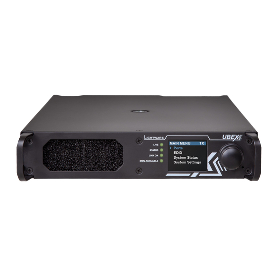
2. Product Overview 2. Product Overview UBEX series – Extender Application Mode – User's Manual UBEX series – Extender Application Mode – User's Manual 2.1. Front and Rear View - F-series Endpoint Devices 2.1.1. Front View Status LEDs All Models... -
Page 15: Rear View
RS-232 Connector in the Video Interface section. section, about the cable wiring in the Cable UBEX-PRO20-HDMI-F110 Wiring Guide for Serial Data Transmission SFP+ port Optical port slots for 2x 10 GbE SFP+ section, and the concept of the operation in slots modules or 2x 10 GbE DAC cables. -
Page 16: Front And Rear View - R-Series Endpoint Devices
2. Product Overview 2. Product Overview UBEX series – Extender Application Mode – User's Manual UBEX series – Extender Application Mode – User's Manual 2.2. Front and Rear View - R-series Endpoint Devices 2.2.1. Front View All Models Status LEDs... -
Page 17: Rear View
2. Product Overview 2. Product Overview UBEX series – Extender Application Mode – User's Manual UBEX series – Extender Application Mode – User's Manual 2.2.2. Rear View Neutrik Neutrik powerCON TRUE1 NAC3MPX- Neutrik Neutrik opticalCON DUO NO2-4FDW-A UBEX-PRO20-HDMI-R100 2xMM-QUAD and 2xSM-QUAD powerCON AC... -
Page 18: Electrical Connections
UBEX series – Extender Application Mode – User's Manual 2.3. Electrical Connections 2.3.2. AC Power Connection 2.3.4. RS-232 Connector UBEX-PRO20-HDMI-F110 model contains a 3-pole Phoenix connector The following sections describe all possible electrical connections of Standard IEC Connector which is used for RS-232 serial connection. -
Page 19: Hdmi Connector
Does not intermate with CAT6 cable connector NE8MC6-MO and NKE6S* cables. Connector Wiring of LAN Cables drawing Lightware recommends the termination of LAN cables on the basis of TIA/EIA T 568 A or TIA/EIA T 568 B standards. Connector type NO2-4FDW-A NO4FDW-A... -
Page 20: Installation
INFO: The endpoint device is half-rack sized. To order mounting accessories please contact sales@lightware.com. 3.1.1. Mounting Bracket V2 Mounting bracket V2 gives an opportunity to mount the device to any 1U high rack shelf provides mounting holes for fastening two half-rack furniture surface. -
Page 21: Mounting Options - R-Series Endpoint Devices
Rigging the handles with a safety wire rope is highly recommended for safety reasons. To order mounting accessories please contact sales@lightware.com. (Truss clamp and safety wire rope are not available at sales.) Step 2. Two mounting holes on the front ears and two on the back of... - Page 22 3. Installation 3. Installation UBEX series – Extender Application Mode – User's Manual UBEX series – Extender Application Mode – User's Manual Step 4. As a final step, mount the unit in the rack. Standard rack installation ATTENTION! Always use all the four screws for fixing the rack ears to the rack rail.
-
Page 23: Connections
LCD menu - see the details in the Operation Mode section; ▪ via Lightware Device Controller (LDC) software - see the details in the Status Tab section; ▪ via LW3 protocol command - see the details in the Set the Operation Mode section. -
Page 24: F-Series Endpoints - Receiver Operation Mode
User Ethernet is also transmitted over the SFP+ interface so be sure not to create network ▪ loop! ▪ via Lightware Device Controller (LDC) software - see the details in the Status Tab section; ▪ via LW3 protocol command - see the details in the Set the Operation Mode section. -
Page 25: F-Series Endpoints - Transceiver Operation Mode
RS-232 Optionally for RS-232 extension: connect the controlled unit (e.g. 4K TV) to the ▪ via Lightware Device Controller (LDC) software - see the details in the Status Tab section; RS-232 port of the device with a serial cable. -
Page 26: R-Series Endpoints - Transmitter Operation Mode
LCD menu - see the details in the Operation Mode section; ▪ via Lightware Device Controller (LDC) software - see the details in the Status Tab section; ▪ via LW3 protocol command - see the details in the Set the Operation Mode section. -
Page 27: R-Series Endpoints - Receiver Operation Mode
LCD menu - see the details in the Operation Mode section; ▪ via Lightware Device Controller (LDC) software - see the details in the Status Tab section; ▪ via LW3 protocol command - see the details in the Set the Operation Mode section. -
Page 28: R-Series Endpoints - Transceiver Operation Mode
The operation mode of the UBEX endpoint device can be changed using the following methods: ▪ via front panel LCD menu - see the details in the Operation Mode section; via Lightware Device Controller (LDC) software - see the details in the Status Tab section; ▪ ▪... -
Page 29: Connection Between F-Series And R-Series Endpoints
This method does not work in case of using DAC cables in the F-series endpoint device. UBEX-PRO20-HDMI-F100 UBEX-PRO20-HDMI-R100 2xMM-2xDUO 3.4.2. SFP+ to Neutrik opticalCON QUAD UBEX-PRO20-HDMI-F110 UBEX-PRO20-HDMI-R100 2xSM-2xDUO This method is working between the following endpoint models: Connecting Steps F-series endpoint model R-series endpoint model Step 1. -
Page 30: Sfp+ Bidi To Neutrik Opticalcon Duo Bidi
ATTENTION! The 2xSM-BiDi-DUO model does not support the Neutrik opticalCON DUO cross cables. UBEX-PRO20-HDMI-R100 2xSM-BiDi-DUO Please use standard cables only. UBEX-PRO20-HDMI-F110 ATTENTION! Always be sure that the fiber optical mode of the entire fiber optical equipment (SFP+ Connecting Steps modules, LC patch cables, Neutrik connectors, and cables) and R100 endpoint device are the same. -
Page 31: Sfp+ Slot Connection
INFO: It is recommended to install 2x 10 GbE DAC cables in the case of All required settings can be done by control software, the Lightware Device Controller (LDC). See all the HDMI 2.0 (4K@60 Hz 4:4:4) signal transmission. details about it in the Lightware Device Controller (LDC) chapter. -
Page 32: Check The Signal Status
3. Installation 3. Installation UBEX series – Extender Application Mode – User's Manual UBEX series – Extender Application Mode – User's Manual 3.6.4. Check the Signal Status SFP+ Links Check the connection status of the SFP+ links: The Crosspoint menu in the LDC software displays all important information about the incoming, transmitting, and outgoing HDMI signals. -
Page 33: Set The Scaler And The Frame Rate Converter
3. Installation 3. Installation UBEX series – Extender Application Mode – User's Manual UBEX series – Extender Application Mode – User's Manual 3.6.7. Set the Scaler and the Frame Rate Converter Example For HDMI in 1 Set up the scaler and the frame rate converter (FRC) for the best user experience. -
Page 34: Set The Audio Streams
Set up the audio crosspoint settings. Digital and analog audio source streams are also selectable in the case of UBEX-PRO20-HDMI-F110 endpoint device. All audio streams can be selected to all outputs. See more details about the audio crosspoint settings in LDC in the Audio Crosspoint Menu section. -
Page 35: Ubex Concept
The port diagram is valid for the following UBEX endpoint models: Fiber Optical Interface ▪ UBEX-PRO20-HDMI-F100 ▪ UBEX-PRO20-HDMI-F110 After the Ethernet packetizing the two video streams are transmitted to the remote endpoint device via the SFP+ / fiber optical ports. ▪ UBEX-PRO20-HDMI-R100 series... -
Page 36: Receiver Mode
RX HDMI Output 1 and 2 Ports section) and in ▪ UBEX-PRO20-HDMI-F100 ▪ UBEX-PRO20-HDMI-F100 the LDC software (see the details in the FRC - Output Side (RX Mode) ▪ UBEX-PRO20-HDMI-F110 ▪ UBEX-PRO20-HDMI-F110 section). ▪ UBEX-PRO20-HDMI-R100 series ▪ UBEX-PRO20-HDMI-R100 series HDMI Input Modes The HDMI input ports of the receiver cannot accept video signals due to software limitation. -
Page 37: Hdmi Signal Transmission - Example For Tx-Rx Pair
4. UBEX Concept 4. UBEX Concept UBEX series – Extender Application Mode – User's Manual UBEX series – Extender Application Mode – User's Manual 4.1.4. HDMI Signal Transmission - Example for TX-RX Pair HDMI Output Modes The transceiver can transmit HDMI video streams on two HDMI 2.0 output ports. -
Page 38: Hdmi Signal Transmission - Example For Trx-Trx Pair
The local outputs of the transmitter always display the received original video streams and cannot be scaled. 4K laptop Lightware Device Controller (LDC) HDMI in 2 The crosspoint settings are available in LCD menu of the device (see the details in the... -
Page 39: Bandwidth Limitation
4. UBEX Concept 4. UBEX Concept UBEX series – Extender Application Mode – User's Manual UBEX series – Extender Application Mode – User's Manual 4.1.7. Bandwidth Limitation Application of Timing Mode Settings - Example The UBEX endpoints can transmit two video streams at the same time up to 20 Gbps bandwidth. -
Page 40: The Difference Between The Scaler And The Frc - Example
4. UBEX Concept 4. UBEX Concept UBEX series – Extender Application Mode – User's Manual UBEX series – Extender Application Mode – User's Manual 4.1.8. The Difference between the Scaler and the FRC - Example 4.2. Audio Interface The following example helps to understand how works the scaler and the frame rate converter and describes 4.2.1. Transmitter Mode - F100/R100 Models... -
Page 41: Transceiver Mode - F100/R100 Models
Signal Support of the Analog Audio Output audio output port on the remote The UBEX-PRO20-HDMI-F110 endpoint model converts the uncompressed stereo audio stream to analog audio. endpoint. The crosspoint setting The analog audio output port supports PCM audio format up to 48 kHz. -
Page 42: Receiver Mode - F110 Model
The HDMI out 2 port is a local output port, it transmits the audio stream of the HDMI in 2 port directly. The UBEX-PRO20-HDMI-F110 endpoint model converts the uncompressed stereo audio stream to analog audio. The HDMI input 1 port does not accept signal when the device is configured as transceiver. -
Page 43: Audio Signal Transmission - Example For Tx-Rx Pair
4. UBEX Concept 4. UBEX Concept UBEX series – Extender Application Mode – User's Manual UBEX series – Extender Application Mode – User's Manual 4.2.7. Audio Signal Transmission - Example for TX-RX Pair 4.2.8. Audio Signal Transmission - Example for TRX-TRX Pair The Concept The Concept... -
Page 44: Ethernet Control Interface
The endpoint device can be controlled via Ethernet port. This interface supports any third-party system controller with LW3 command protocol. The interface can be used to configure the device with Lightware Device Controller and establish the connection to Lightware Device Updater software and perform firmware upgrade. -
Page 45: Serial Interface
UBEX series – Extender Application Mode – User's Manual UBEX series – Extender Application Mode – User's Manual 4.4. Serial Interface 4.5. Infrared Interface DIFFERENCE: Only the UBEX-PRO20-HDMI-F110 model has built with serial interface port. DIFFERENCE: Only the UBEX-PRO20-HDMI-F110 model has built with Infrared interface ports. 4.4.1. Technical Background ATTENTION! The device has no built-in Infrared receiver and transmitter. -
Page 46: Infrared Signal Transmission - Example
4. UBEX Concept 4. UBEX Concept UBEX series – Extender Application Mode – User's Manual UBEX series – Extender Application Mode – User's Manual 4.5.2. Infrared Signal Transmission - Example 4.7. Redundant Fiber Optical Connections The UBEX F-series and R-series endpoint models are built with two equivalent 10 GbE fiber optical channels which are based on a redundant operating principle. -
Page 47: Advanced Edid Management
▪ Lightware Device Controller (LDC) - you can connect to the device via our control software using Ethernet interface and control or configure the device as you wish. For the details see the Lightware Device Controller (LDC) chapter. -
Page 48: Front Panel Lcd Menu Operations
5. Front Panel LCD Menu Operations 5. Front Panel LCD Menu Operations UBEX series – Extender Application Mode – User's Manual UBEX series – Extender Application Mode – User's Manual 5.1. Introduction 5.1.1. Menu Navigation The front panel has a color LCD that shows the most important Menu navigation Menu selection... -
Page 49: The Tree Structure Of The Lcd Menu
5. Front Panel LCD Menu Operations 5. Front Panel LCD Menu Operations UBEX series – Extender Application Mode – User's Manual UBEX series – Extender Application Mode – User's Manual 5.2. The Tree Structure of the LCD Menu 5.3. Ports Menu - Transmitter Mode The most important settings and status MAIN MENU... -
Page 50: Tx Hdmi Input 1 And 2 Ports
5. Front Panel LCD Menu Operations 5. Front Panel LCD Menu Operations UBEX series – Extender Application Mode – User's Manual UBEX series – Extender Application Mode – User's Manual 5.3.1. TX HDMI Input 1 and 2 Ports 5.3.2. RX HDMI Output 1 and 2 Ports 5.3.4. Overview INFO:... -
Page 51: Rx Hdmi Output 1 And 2 Ports
5. Front Panel LCD Menu Operations 5. Front Panel LCD Menu Operations UBEX series – Extender Application Mode – User's Manual UBEX series – Extender Application Mode – User's Manual 5.4.1. RX HDMI Output 1 and 2 Ports 5.5. Ports Menu - Transceiver Mode HDMI Output The following information are displayed in the case of both output... -
Page 52: Local Trx O1 Port
5. Front Panel LCD Menu Operations 5. Front Panel LCD Menu Operations UBEX series – Extender Application Mode – User's Manual UBEX series – Extender Application Mode – User's Manual 5.5.3. Remote TRX I2 Port Video Settings Video Settings The following settings can be set for the stream of the HDMI input 2... -
Page 53: Local Trx O2 Port
5. Front Panel LCD Menu Operations 5. Front Panel LCD Menu Operations UBEX series – Extender Application Mode – User's Manual UBEX series – Extender Application Mode – User's Manual 5.5.5. Local TRX O2 Port 5.6.1. View 5.7. System Status Menu The following information is displayed for the local output port:... -
Page 54: System Settings Menu
5. Front Panel LCD Menu Operations 5. Front Panel LCD Menu Operations UBEX series – Extender Application Mode – User's Manual UBEX series – Extender Application Mode – User's Manual 5.8. System Settings Menu 5.8.3. Application Mode The current application mode (Extender or Matrix) is displayed in this System related settings are available in the menu, e.g. -
Page 55: Lightware Device Controller (Ldc)
Normal install Snapshot install The device can be controlled by a computer through Ethernet interface with the Lightware Device Controller (LDC). The software can be installed on a Windows Available for Windows and macOS Available for Windows PC or macOS. The application and the User’s Manual can be downloaded from... -
Page 56: Running The Ldc
6. Lightware Device Controller (LDC) 6. Lightware Device Controller (LDC) UBEX series – Extender Application Mode – User's Manual UBEX series – Extender Application Mode – User's Manual 6.2. Running the LDC Identifying the Device Clicking on the icon makes the four front panel LEDs blink in green for 10 seconds. -
Page 57: Video Crosspoint Menu
6. Lightware Device Controller (LDC) 6. Lightware Device Controller (LDC) UBEX series – Extender Application Mode – User's Manual UBEX series – Extender Application Mode – User's Manual 6.4. Video Crosspoint Menu Link aggregation Indicates the current status of the SFP+ links. -
Page 58: Transceiver-Transceiver Pair
6. Lightware Device Controller (LDC) 6. Lightware Device Controller (LDC) UBEX series – Extender Application Mode – User's Manual UBEX series – Extender Application Mode – User's Manual 6.4.2. Transceiver-Transceiver Pair 6.4.3. Port Tiles The port tiles and the colors of the displayed icons represent different states and information. -
Page 59: Properties Windows - Video Layer
6. Lightware Device Controller (LDC) 6. Lightware Device Controller (LDC) UBEX series – Extender Application Mode – User's Manual UBEX series – Extender Application Mode – User's Manual 6.5. Properties Windows - Video Layer 6.5.2. Local HDMI Output Ports (TX/TRX Modes) -
Page 60: Frc - Input Side (Tx/Trx Modes)
6. Lightware Device Controller (LDC) 6. Lightware Device Controller (LDC) UBEX series – Extender Application Mode – User's Manual UBEX series – Extender Application Mode – User's Manual 6.5.4. FRC - Input Side (TX/TRX Modes) 6.5.5. Stream Properties Panels (TX/TRX Modes) -
Page 61: Frc - Output Side (Rx Mode)
6. Lightware Device Controller (LDC) 6. Lightware Device Controller (LDC) UBEX series – Extender Application Mode – User's Manual UBEX series – Extender Application Mode – User's Manual 6.5.7. FRC - Output Side (RX Mode) 6.5.8. HDMI Output Ports (RX/TRX Modes) -
Page 62: Stream Switcher / Stream Tiles
6. Lightware Device Controller (LDC) 6. Lightware Device Controller (LDC) UBEX series – Extender Application Mode – User's Manual UBEX series – Extender Application Mode – User's Manual 6.5.10. Stream Switcher / Stream Tiles 6.5.12. Identify Stream / Identify Display... -
Page 63: Audio Crosspoint Menu
Stream 1: the properties of the Stream 1 of the transmitter. DIFFERENCE: Only the UBEX-PRO20-HDMI-F110 model is built with analog audio input and output ports. TX - HDMI in 2 Section of the HDMI in 2 / out 2 ports of the UBEX transmitter. Available panels: and local HDMI ▪... -
Page 64: Properties Windows - Audio Layer
6. Lightware Device Controller (LDC) 6. Lightware Device Controller (LDC) UBEX series – Extender Application Mode – User's Manual UBEX series – Extender Application Mode – User's Manual 6.7. Properties Windows - Audio Layer 6.7.2. Analog Audio Output Port... -
Page 65: Diagnostic Tools
Port Tile HDMI out 2 Lightware’s Frame Detector function works like a signal analyzer and allows to determine the exact video The port tile of the HDMI outputs displays when No sync screen mode format that is present on the port, thus it helps to identify various problems. E.g. actual timing parameters No Sync Screen is active. -
Page 66: Edid Management Menu
6. Lightware Device Controller (LDC) 6. Lightware Device Controller (LDC) UBEX series – Extender Application Mode – User's Manual UBEX series – Extender Application Mode – User's Manual 6.9. EDID Management Menu 6.9.1. EDID Operations Advanced EDID Management can be accessed by selecting the EDID Management menu. -
Page 67: Editing An Edid
EDIT CREATE display Advanced EDID Editor window. The editor can read more detailed knowledge about EDID, Lightware display EDID summary. and write all descriptors, which are defined in the standards, including introduced a wizard-like interface for fast and easy EDID creation. -
Page 68: Control Menu
6. Lightware Device Controller (LDC) 6. Lightware Device Controller (LDC) UBEX series – Extender Application Mode – User's Manual UBEX series – Extender Application Mode – User's Manual 6.10. Control Menu 6.10.2. RS-232 Tab Clicking on the RS-232 port icon results opening the Port properties. -
Page 69: Infra Tab
6. Lightware Device Controller (LDC) 6. Lightware Device Controller (LDC) UBEX series – Extender Application Mode – User's Manual UBEX series – Extender Application Mode – User's Manual 6.10.3. Infra Tab Sending Message via RS-232 Interface The Send message is for sending a command message in ASCII-format. -
Page 70: Settings Menu
6. Lightware Device Controller (LDC) 6. Lightware Device Controller (LDC) UBEX series – Extender Application Mode – User's Manual UBEX series – Extender Application Mode – User's Manual 6.11. Settings Menu 6.11.2. Network Tab INFO: The Settings menu is available for the transmitter, receiver and the transceiver separately. -
Page 71: Configuration Cloning (Backup Tab)
Backup tab and the file of a transceiver can be restored to a transceiver only! The configuration cloning of Lightware LW3 devices is a simple method that eliminates the need to repeatedly WARNING! Please note that the settings will be permanently overwritten with the restored parameters configure certain devices to have identical (non-factory) settings. -
Page 72: Terminal Window
6. Lightware Device Controller (LDC) 6. Lightware Device Controller (LDC) UBEX series – Extender Application Mode – User's Manual UBEX series – Extender Application Mode – User's Manual 6.13. Terminal Window LW3 protocol help Pushing the button results a help window opening which describes the most important information about LW3 protocol commands in HTML format. -
Page 73: Programmers' Reference
UBEX series – Extender Application Mode – User's Manual 7.1. Overview The Lightware Protocol #3 (LW3) is implemented in almost all new Lightware devices (matrix switchers, signal extenders and distribution amplifiers) since 2012. The protocol is ASCII-based and all commands are terminated with a carriage return (Cr, ‘\r’) and line feed (Lf, ‘\n’) pair. It is organized as a tree structure that provides outstanding flexibility and user-friendly handling with ‘nodes’, ‘properties’... -
Page 74: Command Types
7. Programmers’ Reference 7. Programmers’ Reference UBEX series – Extender Application Mode – User's Manual UBEX series – Extender Application Mode – User's Manual 7.2.3. Command Types 7.2.4. Prefix Summary DEFINITION: The prefix is a 2-character long code that describes the type of the response. GET command The following prefixes are defined in the LW3 protocol: The GET command can be used to get the child nodes, properties and methods of a specific node. -
Page 75: Signature
ç OPEN /MANAGEMENT/LABEL æ {1700 æ o- /MANAGEMENT/LABEL æ pr /EDID.EdidStatus=F89:E1;D1:E2 Connection #1 ç GET /MANAGEMENT/LABEL.DeviceLabel æ m- /EDID:copy æ pm /MANAGEMENT/LABEL.DeviceLabel=UBEX-PRO20-HDMI-F110 æ m- /EDID:delete ç GET /MANAGEMENT/LABEL.DeviceLabel æ m- /EDID:reset æ pm /MANAGEMENT/LABEL.DeviceLabel=UBEX-PRO20-HDMI-F110 æ m- /EDID:switch Connection #2 ç SET /MANAGEMENT/LABEL.DeviceLabel=TX_ServerRoom æ... -
Page 76: System Commands
æ used to help to identify the device itself in the rack shelf. Example Command and Response ç GET /.ProductName æ pr /.ProductName=UBEX-PRO20-HDMI-F110 ç CALL•/MANAGEMENT/UI:testDisplay(<mode>,<hex_code>) æ mO•/MANAGEMENT/UI:testDisplay 7.3.3. Query the Firmware Package Version Parameters Command and Response #firmwareversion ç GET•/MANAGEMENT/UID/PACKAGE.Version... -
Page 77: Identify The Device
7. Programmers’ Reference 7. Programmers’ Reference UBEX series – Extender Application Mode – User's Manual UBEX series – Extender Application Mode – User's Manual 7.3.6. Identify the Device 7.3.8. Set the Operation Mode Calling the method results the blinking of the front panel status LEDs for 10 seconds. This feature can be ATTENTION! This operation always requires rebooting the device. -
Page 78: Query The Application Mode
7. Programmers’ Reference 7. Programmers’ Reference UBEX series – Extender Application Mode – User's Manual UBEX series – Extender Application Mode – User's Manual 7.3.9. Query the Application Mode 7.3.11. Setting the Rotary Direction of the Jog Dial Knob The application mode of the device can be Extender or Matrix. -
Page 79: Control Lock
7. Programmers’ Reference 7. Programmers’ Reference UBEX series – Extender Application Mode – User's Manual UBEX series – Extender Application Mode – User's Manual 7.3.13. Control Lock 7.3.15. Restarting the Device Enable/disable the operation of the jog dial control knob. Calling the method results the endpoint restarts –... -
Page 80: Video Port Settings - Transmitter Mode
7. Programmers’ Reference 7. Programmers’ Reference UBEX series – Extender Application Mode – User's Manual UBEX series – Extender Application Mode – User's Manual 7.4. Video Port Settings - Transmitter Mode The Most Common Received Port Status Responses INFO: Video port numbering can be found in the Input/Output Port Numbering... -
Page 81: Query The Status Of Destination Port
7. Programmers’ Reference 7. Programmers’ Reference UBEX series – Extender Application Mode – User's Manual UBEX series – Extender Application Mode – User's Manual 7.4.2. Query the Status of Destination Port 7.4.4. Switching the Stream Command and Response #portstatus Command and Response... -
Page 82: Identify Stream
7. Programmers’ Reference 7. Programmers’ Reference UBEX series – Extender Application Mode – User's Manual UBEX series – Extender Application Mode – User's Manual 7.4.6. Identify Stream 7.4.8. Resolution Mode Setting Calling the method makes generating 10 test colors on the display device for 10 seconds. The feature helps Command and Response to identify the stream and the screen itself physically. -
Page 83: Color Space Converter Setting
7. Programmers’ Reference 7. Programmers’ Reference UBEX series – Extender Application Mode – User's Manual UBEX series – Extender Application Mode – User's Manual 7.4.10. Color Space Converter Setting 7.4.12. HDCP Setting (Input Port) HDCP capability can be enabled/disabled on the input ports, thus, non-encrypted content can be enforced Command and Response #csc #colorspace... -
Page 84: Video Port Settings - Receiver Mode
7. Programmers’ Reference 7. Programmers’ Reference UBEX series – Extender Application Mode – User's Manual UBEX series – Extender Application Mode – User's Manual 7.5. Video Port Settings - Receiver Mode The Most Common Received Port Status Responses INFO: Video port numbering can be found in the Input/Output Port Numbering... -
Page 85: Query The Status Of Destination Port
7. Programmers’ Reference 7. Programmers’ Reference UBEX series – Extender Application Mode – User's Manual UBEX series – Extender Application Mode – User's Manual 7.5.2. Query the Status of Destination Port 7.5.5. Enable/Disable the Stream Command and Response #portstatus Command and Response... -
Page 86: Query The Edid Based Resolution
7. Programmers’ Reference 7. Programmers’ Reference UBEX series – Extender Application Mode – User's Manual UBEX series – Extender Application Mode – User's Manual 7.5.7. Query the EDID Based Resolution 7.5.10. Color Space Converter Setting Command and Response Command and Response #csc #colorspace... -
Page 87: Timing Mode Setting
7. Programmers’ Reference 7. Programmers’ Reference UBEX series – Extender Application Mode – User's Manual UBEX series – Extender Application Mode – User's Manual 7.5.12. Timing Mode Setting 7.5.14. No Sync Screen (Test Pattern) Color Setting The timing mode is set with the following command. -
Page 88: Identify Display
7. Programmers’ Reference 7. Programmers’ Reference UBEX series – Extender Application Mode – User's Manual UBEX series – Extender Application Mode – User's Manual 7.5.16. Identify Display 7.6. Video Port Settings - Transceiver Mode Calling the method makes generating 10 test colors on the display device for 10 seconds. -
Page 89: Query The Status Of Destination Port
7. Programmers’ Reference 7. Programmers’ Reference UBEX series – Extender Application Mode – User's Manual UBEX series – Extender Application Mode – User's Manual 7.6.2. Query the Status of Destination Port The Most Common Received Port Status Responses Command and Response #poststatus ç... -
Page 90: Identifystream #Identifydisplay
7. Programmers’ Reference 7. Programmers’ Reference UBEX series – Extender Application Mode – User's Manual UBEX series – Extender Application Mode – User's Manual 7.6.4. Identify Stream / Identify Display 7.6.6. Resolution Mode Setting - Output Side Calling the method makes generating 10 test colors on the display device for 10 seconds. -
Page 91: Resolution Setting
7. Programmers’ Reference 7. Programmers’ Reference UBEX series – Extender Application Mode – User's Manual UBEX series – Extender Application Mode – User's Manual 7.6.8. Resolution Setting 7.6.10. Color Space Converter Setting The resolution which are set here will be enforced only in case of the ResolutionMode is set to Forced. See Command and Response #csc #colorspace the details about the Resolution Mode Setting in the previous sections. -
Page 92: Timing Mode Setting
7. Programmers’ Reference 7. Programmers’ Reference UBEX series – Extender Application Mode – User's Manual UBEX series – Extender Application Mode – User's Manual 7.6.12. Timing Mode Setting 7.6.14. No Sync Screen (Test Pattern) Color Setting The timing mode is set with the following command. -
Page 93: Audio Port Settings
7. Programmers’ Reference 7. Programmers’ Reference UBEX series – Extender Application Mode – User's Manual UBEX series – Extender Application Mode – User's Manual 7.7. Audio Port Settings The Most Common Received Port Status Responses INFO: Audio port numbering can be found in the Input/Output Port Numbering... -
Page 94: Query The Status Of Destination Port
7.8. Analog Audio Port Settings 7.7.3. Query the Audio Crosspoint Setting DIFFERENCE: Only the UBEX-PRO20-HDMI-F110 model is built with analog audio input and output ports. Displays the current crosspoint setting which audio stream is transmitted to the output ports of the device. INFO:... -
Page 95: Setting The Volume In Percent
7. Programmers’ Reference 7. Programmers’ Reference UBEX series – Extender Application Mode – User's Manual UBEX series – Extender Application Mode – User's Manual 7.8.2. Setting the Volume in Percent 7.8.5. Mute/Unmute the Analog Audio Output Port DIFFERENCE: The setting is available on the analog audio output port only. -
Page 96: Query Video Signal Presence
SignalPresent property indicates valid signal present on the port. MuteStatus property indicates the current status of the analog audio output port. DIFFERENCE: Only the UBEX-PRO20-HDMI-F110 model is built with analog audio output port. Command and Response ç GET•/MEDIA/VIDEO/<in|out|source|destination>.SignalPresent Command and Response pr•/MEDIA/VIDEO/<in|out|source|destination>.SignalPresent=<parameter>... -
Page 97: Query The Resolution Of The Stream
7. Programmers’ Reference 7. Programmers’ Reference UBEX series – Extender Application Mode – User's Manual UBEX series – Extender Application Mode – User's Manual 7.9.6. Query the Resolution of the Stream 7.9.9. Query the Link Aggregation Status Querying of the recent status of the link aggregation between the SFP+ links. -
Page 98: Query The Part Number
7. Programmers’ Reference 7. Programmers’ Reference UBEX series – Extender Application Mode – User's Manual UBEX series – Extender Application Mode – User's Manual 7.10.2. Query the Part Number 7.10.5. Query the Type of the Module Querying of the part number of the installed SFP+ module. -
Page 99: Query The Validity Of A Dynamic Edid
7. Programmers’ Reference 7. Programmers’ Reference UBEX series – Extender Application Mode – User's Manual UBEX series – Extender Application Mode – User's Manual 7.11.2. Query the Validity of a Dynamic EDID 7.11.5. Copy an EDID to User Memory 7.12. Network Configuration Command and Response Command and Response... -
Page 100: Query The Ip Address
7.12.4. Query the IP Address 7.12.8. Query the Gateway Address 7.13. RS-232 Port Configuration Command and Response Command and Response DIFFERENCE: Only the UBEX-PRO20-HDMI-F110 model has built with serial interface port. #rs232 #rs-232 #serial ç GET•/MANAGEMENT/NETWORK.IpAddress ç GET•/MANAGEMENT/NETWORK.GatewayAddress 7.13.1. Query the Current Configuration pr•/MANAGEMENT/NETWORK.IpAddress=<IP_address>... -
Page 101: Parity Setting
UBEX series – Extender Application Mode – User's Manual 7.13.3. Parity Setting 7.13.5. Databits Setting 7.14. Infrared Port Configuration Command and Response Command and Response DIFFERENCE: Only the UBEX-PRO20-HDMI-F110 model has built with Infrared interface port. #infra #ir SET•/MEDIA/UART/<port>.Parity=<number> SET•/MEDIA/UART/<port>.DataBits=<number> ç ç Parameters pw•/MEDIA/UART/<port>.Parity=<number>... -
Page 102: Change Command Injection Port Number
Escaping in the Message DIFFERENCE: Only the UBEX-PRO20-HDMI-F110 model has built with serial and Infrared interface ports. When commands need to be separated by <CR><LF> characters to be recognized by the controlled device, then they need to be escaped. You can use the following format for escaping: 7.15.1. Sending a Text (ASCII-format) via Serial Port... -
Page 103: Sending Hex Codes In Little-Endian Format Via Ir Port
Step 3. Remove all the non-hexadecimal characters (e.g. spaces, h characters etc.) from the code. The pronto hex code which learned by a Lightware device is big-endian format. Applied F-series endpoint firmware package: v1.4.1 | Applied R-series endpoint firmware package: v1.4.1 | LDC software: v1.34.0b2... -
Page 104: Lw3 Protocol Commands - Quick Summary
7. Programmers’ Reference 7. Programmers’ Reference UBEX series – Extender Application Mode – User's Manual UBEX series – Extender Application Mode – User's Manual 7.16. LW3 Protocol Commands - Quick Summary Restarting the Device ç... - Page 105 7. Programmers’ Reference 7. Programmers’ Reference UBEX series – Extender Application Mode – User's Manual UBEX series – Extender Application Mode – User's Manual Video Port Settings - Receiver Mode Video Port Settings - Transceiver Mode Query the Status of Source Port Query the Status of Source Port ç...
- Page 106 7. Programmers’ Reference 7. Programmers’ Reference UBEX series – Extender Application Mode – User's Manual UBEX series – Extender Application Mode – User's Manual Audio Port Settings System Monitoring Commands Query the Status of Source Port Query Connected Device Presence ç...
- Page 107 7. Programmers’ Reference 7. Programmers’ Reference UBEX series – Extender Application Mode – User's Manual UBEX series – Extender Application Mode – User's Manual EDID Management Change the Gateway Address (Static) SET•/MANAGEMENT/NETWORK.StaticGatewayAddress=<gw_address> ç...
- Page 108 7. Programmers’ Reference 7. Programmers’ Reference UBEX series – Extender Application Mode – User's Manual UBEX series – Extender Application Mode – User's Manual Message Sending via Communication Ports Sending a Text (ASCII-format) via Serial Port ç...
-
Page 109: Firmware Upgrade
The firmware files are packed in an LFP2 package. You need only this has the same look and functionality. The endpoint devices can be upgraded by using Lightware Device Updater v2 file to do the upgrade on your device. (LDU2) software via Ethernet. The firmware pack with the necessary components 8.4. Detailed Instructions... - Page 110 After launching LDU2 the device discovery an empty window appears. Click on the Search for devices button When the discovery has completed, the devices available on the network are listed in the application. to start finding the Lightware devices on the network. Legend of the Icons...
- Page 111 8. Firmware Upgrade 8. Firmware Upgrade UBEX series – Extender Application Mode – User's Manual UBEX series – Extender Application Mode – User's Manual Upgrade Steps Step 2. Select the remote unit first for upgrading. Step 1.
- Page 112 8. Firmware Upgrade 8. Firmware Upgrade UBEX series – Extender Application Mode – User's Manual UBEX series – Extender Application Mode – User's Manual Step 3. Check the upgrade parameters. Step 4. Start the update and wait until it is finished. ATTENTION! The default settings in the Parameters window should be fine for most cases.
-
Page 113: Keeping The Configuration Settings
In the case of factory reset you can save the settings of the device in the Lightware Device Controller software and restore it later. See the details in the Configuration Cloning (Backup Tab) section. -
Page 114: Troubleshooting
9. Troubleshooting 9. Troubleshooting UBEX series – Extender Application Mode – User's Manual UBEX series – Extender Application Mode – User's Manual 9.1. Use Cases At first, check front panel LEDs and take the necessary steps according to their states. For more information about status, LEDs refer to the Front and Rear View - F-series Endpoint Devices section. - Page 115 9. Troubleshooting 9. Troubleshooting UBEX series – Extender Application Mode – User's Manual UBEX series – Extender Application Mode – User's Manual Symptom Root cause Action Refer to Symptom Root cause Action Refer to Video signal Audio signal...
-
Page 116: How To Speed Up The Troubleshooting Process
▪ software. The more of the above information you can give us the better. Please send these information to the Lightware Support Team (support@lightware.com) to speed up the troubleshooting process. Applied F-series endpoint firmware package: v1.4.1 | Applied R-series endpoint firmware package: v1.4.1 | LDC software: v1.34.0b2... -
Page 117: Technologies
(dynamic EDID emulation). information about additional Detailed Timings, audio capabilities, For example, the Lightware device can be set up to emulate a sink speaker allocation and HDMI capabilities. It is important to know that device, which is connected to one of the outputs. -
Page 118: Hdcp Management
HDCP v2.2 on the input and encrypted with HDCP v1.4 on the output disabled in the Lightware device. If HDCP is disabled, the connected of the Lightware device. A lower level of encryption may be applied source will detect that the sink is not HDCP capable, and turn off... -
Page 119: Pixel Accurate Reclocking
Too much noise results in increased jitter. different wire construction (impedance mismatch) in DVI cable. It results in jitter. What Kind of Signal Will be on the Output of the Lightware Device? See below table that summarizes the possible cases: HDCP v1.4 HDCP v2.2. -
Page 120: Av Over Ip
10. Technologies 10. Technologies UBEX series – Extender Application Mode – User's Manual UBEX series – Extender Application Mode – User's Manual 10.4. AV Over IP Example for the Link Aggregation Protocol 10.4.1. Basics Beside the traditional AV matrix switchers and extenders the AV over IP or networked AV system is the biggest leading technology in the AV industry. -
Page 121: Assembly Guides
The front plate can be changed on the following endpoint models: ▪ UBEX-PRO20-HDMI-F100 Assembly Guides ▪ UBEX-PRO20-HDMI-F110 11.1.1. Tool Requirements This chapter contains step-by-step assembly guides for the UBEX series devices like the following: ç Front Plate Exchange for F-series Endpoint Devices Step 3. - Page 122 11. Assembly Guides 11. Assembly Guides UBEX series – Extender Application Mode – User's Manual UBEX series – Extender Application Mode – User's Manual Step 5. Remove the front plate from the chassis. Insertion of the New Front Plate Step 3.
-
Page 123: Hidden Usb Connector For Debug Purpose
UBEX endpoints are built with a standard USB 2.0 mini B-type connector which is hidden under the jog dial control knob. ATTENTION! The USB connector is for debug purpose. Please use it only in case of the Lightware Support requests it. Follow the steps to reach the hidden USB connector: Step 1. -
Page 124: Sfp+ Module Changing In R-Series Endpoints
11. Assembly Guides 11. Assembly Guides UBEX series – Extender Application Mode – User's Manual UBEX series – Extender Application Mode – User's Manual 11.3. SFP+ Module Changing in R-series Endpoints Step 4. Remove all five screws from the top cover of the device (highlighted below with green). The R-series endpoint devices are built with pre-installed SFP+ modules inside the enclosure. -
Page 125: Appendix
Power over Ethernet (PoE) ..........Not supported ç Release Notes of the Firmware Packages ITE compliance ............IEC 60950-1:2005 ç Resolutions of the Scaler / FRC 12.1.2. UBEX-PRO20-HDMI-F110 Power source ..........IEC 100-230 V AC, 50/60 Hz ç Factory EDID List General Power Consumption ç... -
Page 126: Ubex-Pro20-Hdmi-R100 Series
12. Appendix 12. Appendix UBEX series – Extender Application Mode – User's Manual UBEX series – Extender Application Mode – User's Manual 12.1.3. UBEX-PRO20-HDMI-R100 series Power Consumption Ethernet Ports Number of ports ..................3 General Resolution TX mode... -
Page 127: Maximum Fiber Cable Extensions
12. Appendix 12. Appendix UBEX series – Extender Application Mode – User's Manual UBEX series – Extender Application Mode – User's Manual 12.2. Maximum Fiber Cable Extensions Video Ports 2xSM-QUAD Number of ports ....... 2x HDMI inputs, 2x HDMI outputs Number of ports ..................1 12.2.1. F-series Endpoints Port connector type ...... -
Page 128: Input/Output Port Numbering
12. Appendix 12. Appendix UBEX series – Extender Application Mode – User's Manual UBEX series – Extender Application Mode – User's Manual 12.3. Input/Output Port Numbering 12.3.2. UBEX-PRO20-HDMI-F100 / R100 - Receiver Mode 12.3.3. UBEX-PRO20-HDMI-F100 / R100 - Transceiver Mode 12.3.1. UBEX-PRO20-HDMI-F100 / R100 - Transmitter Mode Video port nr. -
Page 129: Ubex-Pro20-Hdmi-F110 - Transmitter Mode
12. Appendix 12. Appendix UBEX series – Extender Application Mode – User's Manual UBEX series – Extender Application Mode – User's Manual 12.3.4. UBEX-PRO20-HDMI-F110 - Transmitter Mode Video Port Diagram Audio-Video Port Numbering Table Description Video port nr. (LW3) Audio port nr. -
Page 130: Ubex-Pro20-Hdmi-F110 - Receiver Mode
12. Appendix 12. Appendix UBEX series – Extender Application Mode – User's Manual UBEX series – Extender Application Mode – User's Manual 12.3.5. UBEX-PRO20-HDMI-F110 - Receiver Mode Video Port Diagram Audio-Video Port Numbering Table Description Video port nr. (LW3) Audio port nr. -
Page 131: Ubex-Pro20-Hdmi-F110 - Transceiver Mode
12. Appendix 12. Appendix UBEX series – Extender Application Mode – User's Manual UBEX series – Extender Application Mode – User's Manual 12.3.6. UBEX-PRO20-HDMI-F110 - Transceiver Mode Video Port Diagram Audio-Video Port Numbering Table Description Video port nr. (LW3) Audio port nr. -
Page 132: Control Port Numbering - Endpoint Devices
12. Appendix 12. Appendix UBEX series – Extender Application Mode – User's Manual UBEX series – Extender Application Mode – User's Manual 12.3.7. Control Port Numbering - Endpoint Devices 12.4.2. UBEX-PRO20-HDMI-F110 Parameter Setting/Value Timing mode Free run Parameter Setting/Value... -
Page 133: Content Of Backup File
12. Appendix 12. Appendix UBEX series – Extender Application Mode – User's Manual UBEX series – Extender Application Mode – User's Manual 12.5. Content of Backup File 12.5.2. UBEX-PRO20-HDMI-F100 / R100 - Receiver Mode Parameter Setting/Value Analog audio input port properties... -
Page 134: Ubex-Pro20-Hdmi-F100 / R100 - Transceiver Mode
12. Appendix 12. Appendix UBEX series – Extender Application Mode – User's Manual UBEX series – Extender Application Mode – User's Manual 12.5.3. UBEX-PRO20-HDMI-F100 / R100 - Transceiver Mode 12.5.4. UBEX-PRO20-HDMI-F110 - Transmitter Mode 12.5.5. UBEX-PRO20-HDMI-F110 - Receiver Mode General General General Application mode selection setting... -
Page 135: Ubex-Pro20-Hdmi-F110 - Transceiver Mode
12. Appendix UBEX series – Extender Application Mode – User's Manual UBEX series – Extender Application Mode – User's Manual 12.5.6. UBEX-PRO20-HDMI-F110 - Transceiver Mode 12.6. Release Notes of the Firmware Packages Bugfix: ▪ Fixed a glitch with some 10G switches not switching streams 12.6.1. Release Notes... -
Page 136: Known Issues
12. Appendix 12. Appendix UBEX series – Extender Application Mode – User's Manual UBEX series – Extender Application Mode – User's Manual 12.7. Resolutions of the Scaler / FRC v1.1.0b6 Resolution Comment The following list contains the resolutions and refresh rates which Release date: 2018-06-25 1920 x 1080 @ 30... -
Page 137: Factory Edid List
12. Appendix 12. Appendix UBEX series – Extender Application Mode – User's Manual UBEX series – Extender Application Mode – User's Manual 12.8. Factory EDID List Mem. Resolution Type Mem. Resolution Type Mem. Resolution Type Mem. -
Page 138: Mechanical Drawings
12.9. Mechanical Drawings Bottom View 12.9.1. UBEX F-series Endpoint Devices The following drawings present the physical dimensions of the UBEX F-series endpoints. Dimensions are in Affected models: ▪ UBEX-PRO20-HDMI-F100 ▪ UBEX-PRO20-HDMI-F110 Front View M3 thread M3 thread 21.25 67.5 43.5 67.5 21.25... -
Page 139: Ubex R-Series Endpoint Devices
12. Appendix 12. Appendix UBEX series – Extender Application Mode – User's Manual UBEX series – Extender Application Mode – User's Manual 12.9.2. UBEX R-series Endpoint Devices Side View The following drawings present the physical dimensions of the UBEX R-series endpoints. Dimensions are in Affected models: ▪... -
Page 140: Required Bandwidth Of The Resolutions
12. Appendix 12. Appendix UBEX series – Extender Application Mode – User's Manual UBEX series – Extender Application Mode – User's Manual 12.10. Required Bandwidth of the Resolutions The following table contains the bandwidth requirement when transmitting one or two AV signals together. The table is grouped by resolution, color space, and color depth. The values are in Gb/s. TX - Stream 1 1280x720p60 (720p) 1920x1080p60 (1080p) -
Page 141: Cable Wiring Guide
Symmetric audio is most often referred to as balanced audio, as opposed to asymmetric, which is referred to as unbalanced audio. Lightware products are usually built with 5-pole Phoenix connectors so we would like to help users assembling their own audio cables. -
Page 142: Quick Link Collection
12. Appendix 12. Appendix UBEX series – Extender Application Mode – User's Manual UBEX series – Extender Application Mode – User's Manual 12.12. Quick Link Collection Front Front Activity Activity panel comm. panel comm. - Page 143 12. Appendix 12. Appendix UBEX series – Extender Application Mode – User's Manual UBEX series – Extender Application Mode – User's Manual Front Front Activity Activity panel comm. panel comm. EDID Management Network Copy / save a user EDID 5.6.3...
-
Page 144: Hashtag Keyword List
This keyword is placed at the DHCP (dynamic IP address) setting in #infra Infrared port related settings #transmitter Operation mode (TX/RX/TRX) setting the front panel operation, the Lightware Device Controller (LDC) and #ipaddress IP address related settings #trx Operation mode (TX/RX/TRX) setting the LW3 programmer's reference section. -
Page 145: Further Information
1.4. Product failures from six (6) months to the end of the warranty Added videowall application, added period will either be repaired or replaced at the discretion of Lightware. Infrared interface support, added If Lightware chooses to replace the product then the replacement will...
Need help?
Do you have a question about the UBEX-PRO20-HDMI-F110 and is the answer not in the manual?
Questions and answers