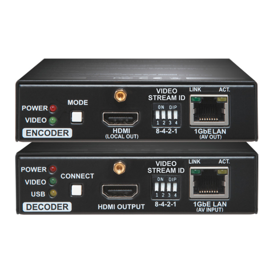
VINX-1x0-HDMI Extenders – User's Manual Important Safety Instructions Waste Electrical & Electronic Equipment Common Safety Symbols WEEE Class II apparatus construction. This marking shown on the product or its literature, Symbol Description The equipment should be operated only from the power source indicates that it should not be disposed with other indicated on the product.
Useful information to perform a successful procedure; it is recommended to read. Web version 1.3.0 Firmware package version 1.4.0 Lightware Device Controller 1.26.1 DIIIERENCEG! Feature or function that is available with a specific firmware/hardware version or product variant. Document revision: 1.6...
3.1. VINX-120-HDMI-ENC Front and Rear View .........14 5.6.3. Setting the Scaling Mode of the Output Video Signal ....43 5. PROGRAMMERS' REFERENCE ............36 3.2. VINX-110-HDMI-DEC Front and Rear View ........14 5.6.4. Setting the Resolution of the Output Video Signal ......44 3.3. VINX-120AP-HDMI-ENC ...............15 5.1.
Page 5
VINX-1x0-HDMI Extenders – User's Manual 5.9.2. Setting the Working Mode (Unicast/Multicast) ......48 8.4.3. RS-232 Signal Transmission over VINX Devices ......65 5.9.3. Querying the Video Stream ID Setting Method ......49 9. APPENDIX ..................66 5.9.4. Querying the DIP Switch Value ............49 9.1.
EDIDs are stored in the Encoder. Lightware devices contain a label indicating the unique serial number Ahank you for choosing Lightware’s VINX Video Network Extender devices. In of the product. The structure is the following: the first chapter we would like to introduce the device by highlighting the most Devices feature embedded web for control.
1. Introduction VINX-1x0-HDMI Extenders – User's Manual 1.2. Box Contents 1.3. Iptional Accessories 1.4. Ieatures of the Device The following items are supplied in the box: The following items can be purchased optionally for the indicated Video Wall Application device: The VINX devices can be arranged to a Video wall up...
Page 8
1. Introduction VINX-1x0-HDMI Extenders – User's Manual 1.6. Aypical Applications Built-in Website Easy access from a web browser to control and configure the devices – even with a mobile device. USB Extension CVM extension for USB HID (Human Interface Devices, e.g.
In order to get the necessary mounting accessory please VINX devices and put them into a standard rack cabinet (width of the contact sales@lightware.com. Rack shelf is 448 mm – without the ears). Fix the device to the Rack 2.1.1. VESA100 Mounting Adapter for Extenders...
For further information please see the Quick Start Guide of the extender. Rackmount Cage. 2.2.2. Assembling Steps Ither Compatible Devices Step 1. Assembling extender The rackmount cage is compatible with other Lightware extenders, bracket. too: Fasten the mounting bracket HDMI-OPT-TX100 ▪ (highlighted with grey) onto the ▪...
2. Installation VINX-1x0-HDMI Extenders – User's Manual 2.3. Connecting Steps 2.3.2. Point-to-Multipoint Transmission (Multicast Mode) AAAENAIING! Please make sure that the VINX devices within a HDMI Connect an HDMI source device (e.g. a computer) to the HDMI Audio system run the same firmware (package version).
2. Installation VINX-1x0-HDMI Extenders – User's Manual 2.3.3. Point-to-Point Transmission (Unicast Mode) 2.3.4. Installation Checkpoints The followings help to have a successful install: check the below HDMI HDMI Connect an HDMI source device (e.g. a blu-ray player) to the listed settings: HDMI input port of the Encoder.
3. Product Overview VINX-1x0-HDMI Extenders – User's Manual 3.1. VINX-120-HDMI-ENC Iront and Rear View 3.2. VINX-110-HDMI-DEC Iront and Rear View 2 34 Product Overview The following sections are about the physical structure of the device, input/ output ports and connectors.
3. Product Overview VINX-1x0-HDMI Extenders – User's Manual 3.6. Electrical Connections SIP Slots Microphone Input Port (Return Audio) The module inserted in the SFP slot can be used for network Mono input port for microphones including +20 dB gain in the signal 1 GbE LAN connection (AV transmission).
3. Product Overview VINX-1x0-HDMI Extenders – User's Manual 3.7. Iront Panel LEDs 3.9. DIP Switch Compression Mode Button ▪ Short press (less, than 3 sec): switching between the INFO: However, the colors of the LEDs in the devices are different, The DIP switch can be used to set the Video Stream ID manually (HW Movie and Graphics modes.
3. Product Overview VINX-1x0-HDMI Extenders – User's Manual 3.10. VINX Device Concept 3.11. Video Interface 3.11.1. One-to-one Video Transmission (Unicast Mode) The Encoder and the Decoder devices are arranged in a LAN by The key feature of the VINX series is the AV signal transmission from The following sections describe the modes of the video transmissions.
3. Product Overview VINX-1x0-HDMI Extenders – User's Manual 3.11.2. One-to-All Video Transmission (Multicast Mode) 3.11.3. Layout Examples Awo Video Walls and Local Monitors with Ine Encoder The Encoder and Decoder devices are arranged in a LAN by connecting Ahe Layout Multicast Mode with Video Wall them to an L3 switch.
3. Product Overview VINX-1x0-HDMI Extenders – User's Manual 3.12. Analog Audio Interface 3.13. USB Interface Small View and Large View Combined in Multicast Mode Ahe Layout DIIIERENCEG! The analog audio option is available only in VINX AP- USB 1.1 and USB 2.0 data transmission operates between an Encoder series.
3. Product Overview VINX-1x0-HDMI Extenders – User's Manual 3.14. RS-232 Interface Command Injection Mode DEFINITION: The Command Injection mode is like an RS-232–TCP/IP Serial data transmission works between an Encoder and all the bidirectional converter. The mode allows data transmission between connected Decoders which have the same Video Stream ID.
Normal install in case of Windows and results an settings. The other option is to use the Lightware Device Controller (LDC) Step 2. Connect a suitable control device (e.g. computer, mobile updateable version with the same attributes.
4.3.3. Establishing the Connection Launch the LDC software. The Ethernet tab consists of two lists: Favorite Devices: You can add any Lightware device that is ▪ connected via Ethernet and no need to browse all the available devices. Devices can be added by pressing the Add button or marking the desired device by the symbol in the All Devices list.
4. Software Control Options VINX-1x0-HDMI Extenders – User's Manual 4.4. Main Settings The Main Window – Displayed on a Computer The Main Window – Displayed on a Mobile Device...
4. Software Control Options VINX-1x0-HDMI Extenders – User's Manual 4.4.1. General Settings Unicast Mode The Video stream ID is used not only in Multicast mode. To assign an Encoder and a Decoder in Unicast mode, set the same Video stream ID in both devices.
4. Software Control Options VINX-1x0-HDMI Extenders – User's Manual 4.4.2. Video Status and Settings (Encoder) Video Settings Video Bandwidth Settings ▪ The emulated EDID can be selected (see the EDID Operations Compression Mode The properties of the incoming and outgoing video signals are displayed in the following sections.
4. Software Control Options VINX-1x0-HDMI Extenders – User's Manual 4.4.3. Video Status and Settings (Decoder) 4.4.4. Audio Settings The content of the window is almost the same as in the case of the The General audio settings allows selecting the desired audio source Encoder.
4. Software Control Options VINX-1x0-HDMI Extenders – User's Manual 4.5. Crosspoint Menu The page allows the user make crosspoint switches between the encoders and the decoder end-points (individual decoders or video walls) in the system. Only at most the first 16 Encoders shall appear in the Crosspoint page.
The Extended Display Identification Data (EDID) is the passport of the display devices. It contains This feature is a good troubleshooter if compatibility problems occur during system installation. Lightware’s information about the capabilities of the display, such as supported resolutions and audio formats, refresh Frame Detector function works like a signal analyzer and makes possible to determine the exact video rates, the type and the manufacturer of the display device, etc.
4. Software Control Options VINX-1x0-HDMI Extenders – User's Manual 4.6.2. EDID Iperations Changing the Emulated EDID Step 1. Choose the desired EDID list on the source panel and select an EDID. Step 2. Select the Emulated tab on the Destination panel. Step 3.
4. Software Control Options VINX-1x0-HDMI Extenders – User's Manual 4.7. Advanced Settings 4.7.1. Common Settings (Encoder and Decoder) The submenu contains two tabs: Multicast and Unicast. The currently valid mode is highlighted with yellow. Press the desired button to choose the mode and access the settings.
4. Software Control Options VINX-1x0-HDMI Extenders – User's Manual 4.7.2. Decoder-related Settings OSD Settings (the On-Screen Display Feature) Certain system messages can be displayed on the connected screen; the followings are defined: ▪ Enable OSD: set it to 'ON' state to enable the OSD feature. ▪...
VINX-1x0-HDMI Extenders – User's Manual 4.7.3. LW3 Aerminal This window is the surface of the Lightware Protocol 3 (LW3) tree with a terminal window. Commands and specific parameters (which are not available on the graphical user interface of the LDC) can be run and set.
4. Software Control Options VINX-1x0-HDMI Extenders – User's Manual 4.8. Video Wall Setup AAAENAIING! This tab is displayed only when the device is in Multicast mode. Although changing parameters usually takes effect within an acceptable period of time, it might happen that feedback is not received and not visible on the web page for several seconds.
4. Software Control Options VINX-1x0-HDMI Extenders – User's Manual 4.8.2. Identify the Decoders 4.8.4. Modifying a Video Wall ▪ No Gap: The left figure shows that no gap is defined. In this case, the whole image is shown on the screens but the image looks The Decoders of a video wall can be identified Ahe Name of the Video Wall Identify Receivers...
VINX-1x0-HDMI Extenders – User's Manual 5.1. Iverview 5.2.2. Ahe LW3 Command Structure Path of the method/property The Lightware Protocol #3 (LW3) is implemented in almost all new Lightware devices (matrix switchers, signal extenders and distribution Command type Method/property amplifiers) since 2012. The protocol is ASCII-based and all commands...
5. Programmers' Reference VINX-1x0-HDMI Extenders – User's Manual 5.2.5. Command Aypes 5.2.6. Prefix Summary The original message: CALL /MEDIA/UART/P1:sendMessage(Set(01)) DEFINITION: The prefix is a 2-character long code that describes GEA command the type of the response. The escaped message: The GET command can be used to get the child nodes, properties and The following prefixes are defined in the LW3 protocol:...
5. Programmers' Reference VINX-1x0-HDMI Extenders – User's Manual 5.2.10. Signature DEFINITION: The signature is a four-digit-long hexadecimal value that can be optionally placed before every command to keep a command and the corresponding responses together as a group. Each line is terminated with a carriage return (Cr, ‘\r’) and line feed (Lf, ‘\n’) characters.
5. Programmers' Reference VINX-1x0-HDMI Extenders – User's Manual 5.4. Network Configuration 5.4.3. Setting the DHCP State Command and Response AAAENAIING! When you change a network property the new value is stored but the applySettings method must be called always to apply the new settings. When two or more serial parameters are changed the SET•/MANAGEMENT/NETWORK.DhcpEnabled=<DHCP_state>...
5. Programmers' Reference VINX-1x0-HDMI Extenders – User's Manual 5.4.6. Setting a Static Subnet Mask 5.5. Encoder-related Commands When the DhcpEnabled property is false you can set a static subnet mask (dot-decimal notation). 5.5.1. Querying the Input Video Signal Presence Command and Response The input port can be queried if video signal is present.
5. Programmers' Reference VINX-1x0-HDMI Extenders – User's Manual 5.5.4. Querying the Video Input Selection Mode 5.5.6. Querying the Video Quality Mode DIIIERENCEG! Below command is valid for VINX-210AP-HDMI-ENC device only. When the network bandwidth is not enough to transmit the video signal the following modes are available in the Encoder: Command and Response Movie mode (Lower image quality @ Less bandwidth): The image quality is adjusted to the available...
5. Programmers' Reference VINX-1x0-HDMI Extenders – User's Manual 5.5.8. Querying the HDCP State 5.6. Decoder-related Commands The current state of the HDCP encryption can be queried at the input port; see the HDCP Management section. 5.6.1. Querying the Resolution of the Output Video Signal Command and Response The resolution and the refresh rate of the outgoing video signal can be queried.
5. Programmers' Reference VINX-1x0-HDMI Extenders – User's Manual 5.6.4. Setting the Resolution of the Iutput Video Signal 5.6.6. Setting the Signal Aype of the Iutput Video Signal The resolution and the refresh rate of the outgoing video signal can be set. Command and Response Command and Response SET•/MEDIA/VIDEO/<out>/SCALER.SignalType=<sig_type>...
5. Programmers' Reference VINX-1x0-HDMI Extenders – User's Manual 5.7. Audio-related Commands 5.7.3. Querying the Audio Signal Presence Command and Response DIIIERENCEG! The following commands refer to the AP-series only. ç GET•/MEDIA/AUDIO/<in>.SignalPresent The port numbering is a required parameter in most cases. See the details in the Audio Port Numbering section.
Page 46
5. Programmers' Reference VINX-1x0-HDMI Extenders – User's Manual 5.7.4.3. Setting the Volume (by a Step Value) 5.7.4.6. Setting the Volume (by a Step Value in Percantage) Command and Response Command and Response CALL•/MEDIA/AUDIO/<port>:stepVolumeDb=<value> CALL•/MEDIA/AUDIO/<port>:stepVolumePercent=<value> ç ç æ...
5. Programmers' Reference VINX-1x0-HDMI Extenders – User's Manual 5.8. Serial Port Settings 5.8.3. Setting the RS-232 Port Mode The RS-232 port can be set to Pass-through or Command Injection mode. The introduction of these modes can AAAENAIING! The new port settings are stored but applied only if the applySettings method is called which be found in the...
5. Programmers' Reference VINX-1x0-HDMI Extenders – User's Manual 5.9.3. Querying the Video Stream ID Setting Method 5.9.5. Querying the Video Stream ID The Video stream ID can be set by the front panel DIP switch or by software. The response of the below command contains the current Video Stream ID, but contains no information about the setting method (HW setting/SW setting).
5. Programmers' Reference VINX-1x0-HDMI Extenders – User's Manual 5.10. Video Wall Settings 5.10.2. Assigning a Decoder to a Video Wall AAAENAIING! Setting the name of the video wall is highly recommended (see the previous section). Basic Rules Command and Response One Decoder can be a part of only one video wall.
5. Programmers' Reference VINX-1x0-HDMI Extenders – User's Manual 5.11. Setting up a Video Wall (Example) Commands Sent to the Decoder (A2) ç SET /MANAGEMENT/MULTICAST.MulticastMode=true The following list of commands show how a video wall can be created by sending LW3 commands. The specifications are the followings: æ...
5. Programmers' Reference VINX-1x0-HDMI Extenders – User's Manual 5.12. Crosspoint Switching Examples 5.12.4. Multiple Switching The commands have to be sent to the Decoders one-by-one thus, the switching ID: 1 ID: 2 ID: 3 ID: 4 The VINX devices can be arranged and used as a matrix.
5. Programmers' Reference VINX-1x0-HDMI Extenders – User's Manual 5.13. EDID Management (Encoder) 5.13.3. Copying an EDID Command and Response The Advanced EDID Management is available also by sending LW3 protocol commands. The structure of the EDID memory can be found in the EDID Menu section.
5. Programmers' Reference VINX-1x0-HDMI Extenders – User's Manual 5.14. LW3 Commands - Quick Summary System Commands Encoder-related Commands Querying the Product Name Querying the Input Video Signal Presence ç GET•/.ProductName ç GET•/MEDIA/VIDEO/<in>.SignalPresent Setting the Device Label Querying the Resolution of the Input Video Signal SET•/SYS/MB.DeviceLabel=<Custom_name>...
Page 56
5. Programmers' Reference VINX-1x0-HDMI Extenders – User's Manual Setting the Signal Type of the Output Video Signal Serial Port Settings SET•/MEDIA/VIDEO/<out>/SCALER.SignalType=<sig_type> Setting the Port Availability ç Querying the State of the USB Connection SET•/MEDIA/UART/<port>.Enabled=<port_status> ç ç GET•/MEDIA/KM.Controlling Setting the Baud Rate of the Port Establishing the USB Connection SET•/MEDIA/UART/<port>.Baudrate=<Baud_value>...
Page 57
5. Programmers' Reference VINX-1x0-HDMI Extenders – User's Manual Video Wall Settings Setting the Name of the Video Wall SET•/MEDIA/VIDEO/O1/VIDEOWALL.Name=<wall_name> ç Assigning a Decoder to a Video Wall SET•/MEDIA/VIDEO/O1/VIDEOWALL.Layout=<wall_parameters> ç EDID Management (Encoder) Querying the Emulated EDID ç...
LFP2 file support Ahe devices can be upgraded via the built-in web page or by the Lightware Log export Device Updater v2 (LDU2) software. The software is available at www.lightware.com. In order to get the firmware pack with the necessary 6.2.
6. Firmware Upgrade VINX-1x0-HDMI Extenders – User's Manual 6.4.1. Iirmware Upgrading Steps Step 1. Get the necessary firmware pack (*.lfp or *.lfp2 file) and save it to the control device (computer/mobile device). Step 2. Establish the connection from the computer/mobile device to the desired VINX extender as described in the Connecting via the Built-in Web...
VINX-1x0-HDMI Extenders – User's Manual 6.5. Option 2. – Upgrading by LDU2 The Lightware Device Updater v2 (LDU2) software is the comfortable way of upgrading the VINX devices. The advantage is that many devices can be upgraded at the same time by a few clicks.
6. Firmware Upgrade VINX-1x0-HDMI Extenders – User's Manual 6.5.2. Before Starting the Upgrade AAAENAIING! While the firmware is being upgraded, the normal operation mode is suspended as the device is switched to bootload mode. Signal processing is not performed. Do not interrupt the firmware upgrade.
At first, check front panel LEDs and take the necessary steps according to their states. For more information about front and rear panel LEDs of the devices refer to the VINX-120-HDMI-ENC Front and Rear View VINX-110-HDMI-DEC Front and Rear View sections. Symptom...
8.1. EDID Management Problem: “I have changed to a different EDID on an input port of the Lightware device to have a different resolution but 8.1.1. Understanding the EDID nothing happens.” The Extended Display Identification Data (EDID) is the passport of...
VINX Encoder VINX Decoder Non-HDCP TCP/IP requires little central management, and it is designed to make disabled in the Lightware device. If HDCP is disabled, the connected content compliant sink networks reliable, with the ability to recover automatically from the source will detect that the sink is not HDCP capable, and turn off failure of any device on the network.
8. Technologies VINX-1x0-HDMI Extenders – User's Manual 8.4. RS-232 Signal Management (VINX AP-Series) 8.4.3. RS-232 Signal Aransmission over VINX Devices The types of VINX devices from serial data transmission point of view are the followings: 8.4.1. General Information VINX model Unit type There are two types of devices in general serial communication:...
DTS-ES Matrix, DTS-HD High Resolution Audio, DTS-HD Master Audio 9.1.1. VINX Basic Series USB Ports Below specification data refer to the VINX-120-HDMI-ENC and VINX-110-HDMI-DEC devices. USB Port Type (Encoder) ........mini-B type receptacle General USB Port Type (Decoder) ........ type A receptacle, 4 pcs.
9. Appendix VINX-1x0-HDMI Extenders – User's Manual Power USB Ports Frequency response below 50Hz ......... above -3dB Power Supply ........External power adaptor (supplied) USB Port Type (Encoder) ..........B type receptacle * compared to the forward audio signal level Power Adaptor ....In 100-240 V AC 50/60 Hz, Out 12V DC, 3 A USB Port Type (Decoder) ........
9. Appendix VINX-1x0-HDMI Extenders – User's Manual 9.3. Mechanical Drawings The dimensions are in mm. Encoder and Decoder devices have the same size of chassis. The basic VINX devices are built into quarter-rack sized chassis, the AP-series have half-rack sized chassis. Half-rack Sized Models Iront View Bottom View...
▪ Fixed a bug that caused the Programmers' LW3 Terminal window to Open Device. encoder shall be set to the same setting. to be rendered incorrectly at certain resolutions. ▪ From this version on VINX devices are supported by the Lightware Bugfix: v1.1.1b2 Device Manager.
Page 72
9. Appendix VINX-1x0-HDMI Extenders – User's Manual ▪ Version number of several components including package ▪ Switching source or destination through the Device list pane on version has been added to the graphical user interface. the Main Settings page of the encoder or decoder might take more time compared to switching directly by modifying the ID in ▪...
1 GbE L2 switch suggests involvement of both AV and IT departments in any installation. VLAN Voice/Data VLAN Voice/Data CATx CATx Lightware products are designed to be plug-and-play. The figures in VIDEO LINK ACT. VIDEO LINK ACT. POWER STREAM ID...
Page 74
9. Appendix VINX-1x0-HDMI Extenders – User's Manual Managed Switch Properties in Details Multicast Iiltering IGMPv2 Some control information from VINX devices is transmitted via multicast packets. However, these packets are not registered during IGMPv2 is version 2 of the Internet Group Management Protocol. This certain startup intervals or not registered at all.
Crosspoint view added to SW 1.4. Product failures from six (6) months to the end of the warranty control; Crosspoint switching period will either be repaired or replaced at the discretion of Lightware. examples added; Mounting into Laszlo If Lightware chooses to replace the product then the replacement will 1.5 11-01-2019...
Need help?
Do you have a question about the VINX-110-HDMI-DEC and is the answer not in the manual?
Questions and answers