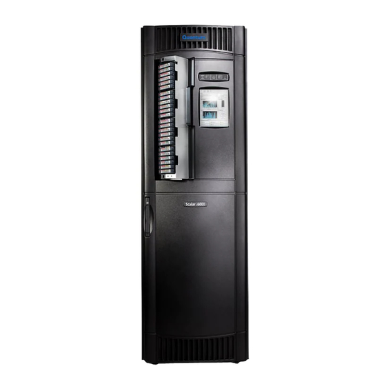
Quantum Scalar i6000 Installation Manual
Tape library
Hide thumbs
Also See for Scalar i6000:
- User manual (738 pages) ,
- Planning manual (92 pages) ,
- Manual (58 pages)

Subscribe to Our Youtube Channel
Related Manuals for Quantum Scalar i6000


Summary of Contents for Quantum Scalar i6000
- Page 1 Scalar 6000 In s talla ti o n Gu ide In st a l l at i o n G u i d e In st al l a ti on Gui d e I nst al l a ti on Guid e 6-66881-01 A...
- Page 2 Scalar i6000 Installation Guide, 6-66881-01 A, May 2010, Made in USA. Quantum Corporation provides this publication “as is” without warranty of any kind, either express or implied, including but not limited to the implied warranties of merchantability or fitness for a particular purpose. Quantum Corporation may revise this publication from time to time without notice.
-
Page 3: Table Of Contents
Setting the Leg Lock Nuts ............25 Scalar i6000 Installation Guide... - Page 4 4 Installing a Multi-Module Library Preparing to Install a New Multi-Module Library ......... . 28 Attaching Control and Expansion Modules as System Units.
- Page 5 Manually Bulk Loading Cartridges........... . 142 Scalar i6000 Installation Guide...
- Page 6 9 Setting up Your Library for Access Launching the Remote Client ............145 Configuring Library Security .
- Page 7 Picker Pivot/Reach ............322 Scalar i6000 Installation Guide...
- Page 8 Verification Test Logs ............323 Running the Installation Verification Test .
- Page 9 Table 24 Explanations of Ethernet Expansion Blade LED States ......359 Scalar i6000 Installation Guide...
- Page 10 Table 25 Explanations of EEB Ethernet Port LED States ....... . . 359 Table 26 Explanations of MCB Ethernet Port LED States .
- Page 11 Figure 24 I/O Management Unit Bay Layout ......... 253 Scalar i6000 Installation Guide...
- Page 12 Figure 25 Verification Tests Dialog Box ..........310 Figure 26 Report Window .
-
Page 13: About This Guide And Your Product
Be sure to read all operating instructions in this manual and in the System, Safety, and Note Regulatory Information Guide before operating this product. This guide is intended to be used by Quantum professional services and service personnel who will service the library. Product Safety Statements This product is designed for data storage and retrieval using magnetic tape. -
Page 14: Mechanical Locks
Mechanical Locks The access and service doors can only be opened with a key. The key should be kept by an authorized person at your company. Access to the interior of the library is both a data integrity and a safety issue. Door Interlock Switches Door interlock switches detect when the access door has been opened and automatically remove power from the picker. -
Page 15: Performing Mechanical Maintenance
Wear safety shoes when handling heavy components. Before you begin work and after you finish, be careful to remove or reinstall all safety provisions as appropriate (covers, hazard alert messages, warning signs, grounding wires, and so forth). Scalar i6000 Installation Guide... -
Page 16: Working On Live Components
Working on Live Components CONTACT WITH ELECTRICAL PARTS CAN CAUSE ELECTRICAL WARNING SHOCK, RESULTING IN POSSIBLE SEVERE OR FATAL BURNS AND INTERNAL INJURY. A PERSON WHO COMES INTO CONTACT WITH A LIVE PART OFTEN CANNOT BREAK LOOSE FROM THE PART. A SECOND PERSON MUST STAND NEAR THE MAIN CIRCUIT BREAKER, READY TO IMMEDIATELY SWITCH IT OFF IF A HAZARDOUS SITUATION OCCURS. -
Page 17: Disposal Of Electrical And Electronic Equipment
For more information about where you can drop off your waste equipment for recycling, please visit our Web site at: http://qcare.quantum.com or contact your local government authority, your household waste disposal service or the business from which you purchased the product. -
Page 18: Product Model Number
Product Model Number The Scalar i6000 Regulatory Model Numbers are as follows: SCi2000 Control Model SCi2000 Expansion Model. Explanation of Symbols and Notes The following symbols appear throughout this document to highlight important information. INDICATES A POTENTIALLY HAZARDOUS SITUATION WHICH, IF NOT WARNING AVOIDED, COULD RESULT IN DEATH OR BODILY INJURY. -
Page 19: Getting More Information Or Help
More information about this product is available on the Service and Support Web site at www.quantum.com/support. The Service and Support Web site contains a collection of information, including answers to frequently asked questions (FAQs). You can also access software, firmware, and drivers through this site. - Page 20 About This Guide and Your Product...
-
Page 21: Getting Started
Make sure you have read the Scalar i6000 Planning Guide before you start the installation procedure. Two silver and two gold keys are shipped with each module. The gold keys (FRU ID 401) open the service door. -
Page 22: Checking The Accessories
• Electrostatic discharge (ESD) wrist strap Library documentation (delivered with each control module): • CD-ROM that contains online versions of documentation • Scalar i6000 Installation Guide (this manual) • Scalar i6000 Unpacking Instructions • Scalar i6000 Release Notes Getting Started... -
Page 23: Initial Setup Procedure Road Map
97 provides install tape instructions for installing and connecting the tape drives and drives in the drive modules. blades Applying Power on page 93, contains instructions for applying power to your library. turn on power Scalar i6000 Installation Guide... - Page 24 Verifying the Hardware Installation on page 307 has verify the the procedure you should use to verify the hardware hardware configuration. Installation Verification Test Overview configuration on page 309 must also be performed. Configuring the Library on page 153 tells you how to set up the library.
-
Page 25: Required Tools
• Measuring tape • Laptop computer • Digital volt meter • Digital level • X-axis rail alignment tool (part number 3-00147-01) • ESD wrist strap • Metric ruler • Small zip ties (quantity 100) • Flashlight Scalar i6000 Installation Guide... -
Page 26: Illustrations Of Modules
Illustrations of Modules An illustration of an 8-module configuration along with figures of the front and back of both the control module and expansion modules are shown on the following pages. Figure 1 Front View of an 8-Module Library expansion modules control module Getting Started... -
Page 27: Figure 2 Front View Of A Two-Module Library
Figure 2 Front View of a Two-Module Library fire suppressant access top cable entry service door indicator panel touch screen access door I/E station expansion module control module Scalar i6000 Installation Guide... -
Page 28: Figure 3 Control Module, Front View Component Location
Figure 3 Control Module, Front View Component Location fire suppressant access picker I/E station drive sled access door magazine leveling foot Getting Started... -
Page 29: Figure 4 Control Module, Rear View Component Location
Figure 4 Control Module, Rear View Component Location top cable entry service door I/O management unit drive clusters library management power distribution units module bottom cable entry power supplies Scalar i6000 Installation Guide... -
Page 30: Figure 5 Expansion Module, Back View Component Location
Figure 5 shows the back of an expansion module. Only expansion modules that contain drives will be delivered with power supplies, which enables them to support the tape drives. Expansion modules in positions 9 -12 are LTO storage-only modules. Figure 5 Expansion Module, Back View Component Location the I/O management unit is installed and blades are... -
Page 31: Installing A Stand-Alone Control Module
Additional Leveling on page 24 • Setting the Leg Lock Nuts on page 25 Required tools: • 24 mm open end wrench • 16 mm open end wrench • 6 mm hex wrench • Digital level Scalar i6000 Installation Guide... -
Page 32: Positioning The Stand-Alone Control Module
Positioning the Stand-Alone Control Module The first steps in setting up a stand-alone control module involve locating and positioning the control module. For more information on location specifications, see the Scalar i6000 Planning Guide. Verify the placement of the control module. -
Page 33: Raising The Control Module Off The Casters
Lowering the Leveling Legs on page 20. The goal is to have the control module weight evenly distributed across all four leveling legs when it is properly raised. The module may or may not be level at this time. Scalar i6000 Installation Guide... -
Page 34: Testing The Digital Level
Testing the Digital Level Required tools: digital level Perform this test before each use of the digital level and any time the digital level has been dropped or is ° being used in an environment that varies ±9 F from the environment in which it was last calibrated. If the digital level fails the accuracy test you must re-calibrate the level before use. -
Page 35: Verifying Level Condition
If the module does not meet the 0.00 +/- 0.30 leveling requirement, go to Additional Leveling on page 24. If the module is sufficiently level, go to Setting the Leg Lock Nuts on page 25. Scalar i6000 Installation Guide... -
Page 36: Additional Leveling
Additional Leveling Customer floors may be such that further leveling is required. The goal in leveling the control module is to adjust the leveling legs to achieve a digital level reading that is 0.00 +/- 0.30. Place the digital level inside the access door. Use the following rules when leveling from left to right: •... -
Page 37: Setting The Leg Lock Nuts
Use the 24 mm open end wrench to raise the four leveling leg lock nuts to the top and tighten them against the welded nut. Ensure that you do not take the leveling legs out of adjustment during this Note process. Scalar i6000 Installation Guide... - Page 38 Installing a Stand-Alone Control Module...
-
Page 39: Installing A Multi-Module Library
13 mm open end wrench • 8 mm nut driver or open end wrench • 6 mm hex wrench • 3 mm hex wrench • 2.5 mm hex wrench • X-axis alignment tool (part number 3-00147-01) • digital level Scalar i6000 Installation Guide... -
Page 40: Preparing To Install A New Multi-Module Library
Preparing to Install a New Multi-Module Library To prepare to install a new multi-module library, complete the following procedures: • Attaching Control and Expansion Modules as System Units on page 28 • Testing the Digital Level on page 31 • Positioning the System Unit on page 30 •... - Page 41 Tighten the bolts using the 6 mm hex wrench and the 13 mm open end wrench. Do not overtighten the bolts. Overtightening can damage the vertical frame Note post structure. Once the frames are aligned and bolted properly together, proceed to Positioning the System Unit page 30. Scalar i6000 Installation Guide...
-
Page 42: Positioning The System Unit
Positioning the System Unit For more information on location specifications, see the Scalar i6000 Planning Guide. Verify the placement of the system unit. The control module is at the left end of a multi-module library. Note Verify the following: •... -
Page 43: Raising The System Unit Off The Casters
Turn on the level by pushing the ON/OFF button. Position the level with the display facing you and the text on the face of the level right-side up. Ensure that the level is on a clean, flat, and horizontal surface. Scalar i6000 Installation Guide... - Page 44 This surface does not have to be exactly level. Wait 10 seconds for the level to completely settle and take note of the angle on the display. Rotate the level end-for-end so the display is facing away from you. The screw on the back of the level should be on the left side.
-
Page 45: Verifying Level Condition
If the module does not meet the 0.00 +/- 0.30 leveling requirement, go to Additional Leveling on page If the module is sufficiently level, go to Lowering All Other Leveling Legs on page 35. Scalar i6000 Installation Guide... -
Page 46: Additional Leveling
Additional Leveling Customer floors may be such that further leveling is required. The goal in leveling the system unit is to adjust the leveling legs to achieve a digital level reading that is 0.00 +/- 0.30. Place the digital level inside the control module access door (positions 1). Use the following rules when leveling from left to right: •... -
Page 47: Lowering All Other Leveling Legs
Note process. If you are installing additional expansion modules to the system unit, proceed to Adding an Expansion Module to an Existing System Unit on page 36. Proceed to Attaching the X-Axis Rails on page 41. Scalar i6000 Installation Guide... -
Page 48: Adding An Expansion Module To An Existing System Unit
Adding an Expansion Module to an Existing System Unit If you are adding one or more expansion modules to an existing library, first go to Preparing an Existing Library to Receive an Expansion Module on page 74, prior to completing the procedures below. To add an expansion module to an existing system unit during a new installation process, complete the following procedures: •... -
Page 49: Installing Expansion Modules After Installing The System Unit
The first steps in adding a new expansion module to a system unit involve locating and positioning the expansion module. For more information on location specifications, see the Scalar i6000 Planning Guide. A label placed on the floor in the rear of the expansion module shows the order Note in which to place the module. -
Page 50: Raising The Expansion Module Off The Casters
Raising the Expansion Module Off the Casters Required tools: 6 mm hex wrench or 16 mm open end wrench Use either the 6 mm hex wrench or 16 mm open end wrench to raise each of the four corner legs of the module seven (7) half turns. -
Page 51: Aligning The New Expansion Module With The System Unit
If the bolt does not slide smoothly into the hole, raise or lower the leveling legs until it does. c. Once the bolt is inserted, loosely thread the nut onto the bolt. Do not tighten the nut. front upper bolt front lower bolt Scalar i6000 Installation Guide... -
Page 52: Tightening The Attachment Bolts
back upper bolt back lower bolt Tightening the Attachment Bolts Once the bolts have been inserted, tighten the bolts using the 6 mm hex wrench and the 13 mm open end wrench. Do not overtighten the bolts. Overtightening can damage the vertical frame Note post structure. -
Page 53: Attaching The X-Axis Rails
Tighten each screw on the rail beginning at the left end. Do not tighten the screw that is on the next rail at the junction between the current module and the module to the right. 2.5 mm hex screw attached to module on left 2.5 mm hex screws Scalar i6000 Installation Guide... - Page 54 Attach the lower X-axis rail as follows: a. Use the 2.5 mm hex screws to attach the lower X-axis rail loosely. b. Push the rail to the left and align it front to back with the previous rail so that the joint is smooth. c.
-
Page 55: Attaching The Middle X-Axis Rail
X-axis rail to install the new rail. See Remov- ing the Middle X-Axis Rail from Module Eight on page 81. Etched part number identifying special rail for adding EM to eight or more library configuration Scalar i6000 Installation Guide... - Page 56 When attached, the middle X-axis rail must appear as shown below. The holes will appear slightly shifted on the 7mm shorter rail. Note middle X-axis X-axis rail channel Installing a Multi-Module Library...
-
Page 57: Aligning The Middle X-Axis Channel
Place the centering tool over screw 3 and into the counterbore of the X-axis rail. b. Holding the centering tool in place, tighten screw 3. c. Repeat for screw 8. counterbore in middle X-axis rail 3 mm screw junction middle X-axis rails x-axis channels Scalar i6000 Installation Guide... -
Page 58: Aligning The Middle X-Axis Rail
Loosen the eight 2.5 mm screws attaching the X-axis channel to the module. alignment pins 2.5 mm screws 2.5 mm screws Push the X-axis channel and middle X-axis rail to the left until the X-axis rail of the expansion module contacts the X-axis rail of the module on the left. -
Page 59: Verifying The Middle X-Axis Rail Alignment
Verify that value for the expansion module middle X-axis rail is within +/- 0.05 degrees of the value recorded for the control module. Make note of this value. If the rail is not within this tolerance, align it as follows: Scalar i6000 Installation Guide... - Page 60 a. Loosen screws 3 through 10 on the middle X-axis rail that is out of alignment. Do not loosen screws 1 and 2 or the rail-to-rail alignment will be lost. Note middle X-axis X-axis rail channel b. Adjust the X-axis rail until the level matches that of the control module, then tighten screw 10. c.
-
Page 61: Verifying Accessor Assembly Alignment
Y-axis rail front edge of Y-drive mount scribe mark on lower X-axis rail b. Verify that the upper X-axis bearing is within one mm of the scribe mark on the upper X-axis rail. Y-axis rail scribe mark Scalar i6000 Installation Guide... -
Page 62: Attaching The Tensioner Bracket And Hard Stop
If the accessor assembly is not aligned correctly, do the following: a. Loosen the five screws that hold the accessor to the X carriage. b. Position the front edge of the Y-drive mount so that it is aligned with the scribe mark on the lower X-axis rail. -
Page 63: Nine Modules Or More Configuration
On the X-axis tensioner that you removed earlier, use a 3 mm hex wrench to remove the 4 screws that attach the tensioner assembly to the tensioner assembly bracket. 3 mm screws Removed tensioner mounting bracket with hole instead of slot black tensioner assembly Scalar i6000 Installation Guide... - Page 64 Using a 3 mm hex wrench install the 4 screws that attach the tensioner assembly to the replacement tensioner bracket. 3 mm screws Replacement tensioner mounting bracket with slot black tensioner assembly Use a 3 mm hex wrench to install the fours screws that attach the X-axis tensioner to the substrate of the last expansion module in your library configuration.
-
Page 65: Installing The X-Axis Belt
Tools required: 2.5 mm hex wrench, 4 mm hex wrench, 3 mm hex wrench Eight Modules or Less Configuration Thread the belt around the back side of the X-axis pulley assembly. thread belt through the back of the pulley assembly belt Scalar i6000 Installation Guide... - Page 66 Thread the end of the belt through the back opening in the tensioner. tensioner thread belt through opening in the back of the tensioner belt Locate the X-axis belt clamp. The X-axis belt clamp was removed as part of the disassembly procedure on an existing library. See Step 5 on page 79.
- Page 67 If your library configuration involves nine or more modules, see Nine Modules or More Configuration on page 56. Otherwise, proceed to step Step 9 on page 56. X-axis carriage 4 mm belt clamp bracket screws belt clamp Scalar i6000 Installation Guide...
- Page 68 Use the 4 mm hex wrench to turn the spring-load screw counter clockwise to uncompress the tensioner. Note that the gap cannot exceed 5 mm between the score mark and the tensioner base. 10 Continue to unscrew the compression screw (turning counterclockwise) until there is a 10 mm gap between the screw head and tensioner base.
- Page 69 Use a 3mm hex wrench to install the remaining three screws and tighten the loosened screw in the vertical slot. Use the 4mm hex wrench to turn the spring-load screw counter clockwise to uncompress the tensioner. 10 Verify that the tensioner gap does not exceed 3.5mm Scalar i6000 Installation Guide...
-
Page 70: Installing The X-Axis Chain Assembly
11 If necessary, repeat steps 3 -10 and remove one belt tooth. 12 Once the tensioner has been uncompressed and the 3.5mm gap has been achieved, secure the belt clamp to the X-axis carriage by installing the two 4mm screws through the X-axis carriage into the belt clamp. - Page 71 Using the 3 mm hex wrench, secure the X-axis chain assembly (W8) to the bottom of the control module using two 3 mm screws. 3 mm screws X-axis chain assembly (W8) Connect the X-axis chain (W8) connector from the control module bulkhead. X-axis chain (W8) connection Scalar i6000 Installation Guide...
- Page 72 Connect the X-axis chain connector (W8) to the control module bulkhead using Velcro straps. Velcro straps Use a 3 mm hex wrench to attach the X-axis chain assembly (W8) to the Y-axis drive mount assembly using two 3 mm screws. 3 mm screws Y-axis drive mount assembly...
- Page 73 Connect the Y-axis motor/home sensor cable to the X-axis chain assembly (W8). X-axis sensor cable X-axis chain assembly (W8) Connect the Y-axis chain (W9) to the X-axis chain assembly (W8). Y-axis chain assembly (W9) connector X-axis chain assembly (W8) Scalar i6000 Installation Guide...
- Page 74 On the top of the X-axis chain assembly, lock down the Y-axis home sensor cable by pressing down on the hold-down. hold down Y-axis home sensor cable Test the Y-axis assembly by moving the accessor assembly to its home position and verifying the cables do not have contact with the cables routed up the bulkhead.
-
Page 75: Installing The X-Axis Chain Trough
Required tools: 2.5 mm hex wrench Locate the X-axis cable trough (part number 3-01740-01). 2.5 mm hex screw cable trough Use the 2.5 mm hex wrench to remove the clip from the end of the trough. Scalar i6000 Installation Guide... - Page 76 Place the trough between the top and bottom portions of the X-axis chain. Clip the end of the trough over the bottom chain of the X-axis cable in the middle of the third module (second expansion module). expansion module in position 3 hook the clipped end of the trough into a lower link of the X-axis cable...
-
Page 77: Routing And Connecting Module Cables
Loosen the thumbscrew on the LBX/IEX cover plate and remove the plate. LBX/IEX cover plate thumbscrew b. Use a #2 Phillips screwdriver to remove the four thumbscrews that retain the cover plate between the top and bottom drive positions. thumbscrews Scalar i6000 Installation Guide... - Page 78 On the new expansion module, loosen the thumbscrew on the LBX/IEX cover plate and remove the plate. LBX/IEX cover plate thumbscrew Locate the W1 and W2 cables on the new expansion module. W2 cable (Ethernet) W1 cable (large ribbon cable) Installing a Multi-Module Library...
- Page 79 349. Make certain you have the correct version LBX based on the library configuration you are installing. LBX board on LBX board on W1 cable control module or expansion module (large ribbon cable) expansion module Scalar i6000 Installation Guide...
- Page 80 Connect the W2 Ethernet cable to the J3 connection on the LBX board on the control module or last expansion module in the existing configuration. This connects the J4 connection on the LBX board in the new expansion module to the J3 connection on the LBX board in the control module or last expansion module in the existing configuration.
- Page 81 Use the cover plate thumbscrew to replace the LBX/IEX cover plates on the modules. LBX/IEX cover plate thumbscrew Use a #2 Phillips screwdriver to replace the cover plate between the drive positions. thumbscrews Scalar i6000 Installation Guide...
-
Page 82: Assembling The Last Expansion Module
Assembling the Last Expansion Module Required tools: 2.5 mm hex wrench, Remove the magazine storage on rack # 1 in sections 1 - 5 on Column 4 in the last expansion module. rack 1 (back) top view of module column 4 rack 1 (back) section 1 rack 2 (front) - Page 83 Install the L brackets. Each bracket is attached to the module frame by two 2.5 mm hex screws. 2.5 mm screws that retain the L-brackets Locate the right side panel that was removed from the control module or previous expansion module. Scalar i6000 Installation Guide...
- Page 84 Align the side cover with the screw holes in the expansion module. screw holes screw holes Installing a Multi-Module Library...
- Page 85 Repeat steps Step 1 on page 70 through Step 3 on page 71 on each expansion module. Once the components are installed, if applicable, perform the procedures detailed in Installing Drives and Blades on page 97. Scalar i6000 Installation Guide...
-
Page 86: Preparing An Existing Library To Receive An Expansion Module
Positioning the Existing Library If you must move the existing library prior to installing a new expansion module, follow the preceding steps to locate and position the modules. For more information on location specifications, see the Scalar i6000 Planning Guide. -
Page 87: Removing The Right Side Panel From The Last Existing Module
Pull the magazine toward you to remove it. rack 1 (back) top view of module column 4 rack 1 (back) section 1 rack 2 (front) section 2 drive cluster section 3 section 4 section 5 drive cluster Scalar i6000 Installation Guide... - Page 88 Remove the nine (9) 2.5 mm screws that attach the right side panel to the module. Three screws are located at the front corner post, three at the back corner post, Note and three at the storage wall. 2.5 mm screw 2.5 mm screws back of module front of module...
- Page 89 Lift the right side panel off the module and set it aside until the expansion module install procedure calls to reinstall it on the last expansion module. screw holes screw holes Scalar i6000 Installation Guide...
- Page 90 Use a 2.5 mm hex wrench to remove the three L-brackets that mount the side panel to the storage wall and set them aside. The L-brackets will be reused to attach the side panel to the last expansion module. 2.5 mm screws retaining L-brackets Reinstall the magazines that were removed in...
-
Page 91: Removing The X-Axis Belt
Take the X-axis belt off the X-axis belt clamp assembly and pull the belt free from the pulleys. Set the belt clamp assembly aside. The assembly will be reused in later steps. Discard the belt. It will not be used in the new configuration. Scalar i6000 Installation Guide... -
Page 92: Removing The Tensioner Bracket And Hard Stop
Removing the Tensioner Bracket and Hard Stop Use a 3 mm hex wrench to remove the four (4) screws that are attaching the X-axis tensioner bracket to the X-axis channel in the control module or last expansion module. Do not use ball drivers to remove the hex screws because the screws Note could be stripped. -
Page 93: Removing The Middle X-Axis Rail From Module Eight
Use a 3 mm hex wrench to remove screws 1 through 10. X-axis channel middle X-axis rail Lift the rail from the frame, and set aside. Scalar i6000 Installation Guide... -
Page 94: Removing The X-Axis Chain Assembly
Removing the X-Axis Chain Assembly On the top of the X-axis chain assembly, release the Y-axis home sensor cable by flipping up the hold- down. hold down Y-axis home sensor cable Disconnect the Y-axis chain (W9) from the X-axis chain assembly (W8). Y-axis chain assembly (W9) connector... - Page 95 3 mm screws X-axis chain assembly Using the 3 mm hex wrench, remove the two screws securing the X-axis chain assembly (W8) to the bottom of the control module. 3 mm screws X-axis chain assembly (W8) Scalar i6000 Installation Guide...
- Page 96 Remove Velcro straps (or zip ties) holding the X-axis chain (W8) to the control module bulkhead. Velcro straps Disconnect the X-axis chain (W8) connector from the control module bulkhead. X-axis chain (W8) connector Remove the X-axis chain from the module and discard it appropriately. It will not be used in the configuration.
-
Page 97: Removing The Lbx Terminator Board
Determine your library configuration and verify what version of LBX terminator is needed. There are two versions of the LBX terminator board (card). For more information, see LBX Terminator on page 349. J17 connection LBX terminator Scalar i6000 Installation Guide... -
Page 98: Removing And Replacing The Lbx Board
Removing and Replacing the LBX Board If you are adding one or more expansion modules to an existing eight-module library, you must remove the LBX2 Gen 2 board from expansion module seven and replace it with the LBX2 GEN 3 version (red sticker identifier). - Page 99 Then use your thumb to unsnap the LBX board from the standoffs. To avoid damage to the backside of the LBX board, you should use care when removing the LBX board from the space above the metallic standoffs. Remove the IEX and LBX boards. Scalar i6000 Installation Guide...
-
Page 100: Replacing The Lbx Board
Replacing the LBX Board Red stickers identify the LBX2 GEN 3 board required in the expansion Note modules added to a library configuration greater than eight. Required Tools: None FRU ID: 104 If the library is not shut down, shut down the library. For more information, see Shutting Down the Library on page 232. -
Page 101: Removing And Replacing The Iex Card
Shutting Down the Library on page 232. Open the service door. Attach the ESD strap to your wrist and to an unpainted surface inside the door. Unscrew the thumbscrew and remove the LBX/IEX cover plate. thumbscrew Scalar i6000 Installation Guide... -
Page 102: Replacing The Iex Board
Use your thumb to unsnap the IEX board from the two standoffs. IEX board standoffs Unplug the IEX board from the LBX board. connection between IEX and LBX boards Remove the IEX board. Replacing the IEX Board Required Tools: None FRU ID: 105 If the library is not shut down, shut down the library. - Page 103 Plug the IEX board into the new LBX board. Use your thumb to snap the IEX board onto the two standoffs. IEX board standoffs Replace the LBX/IEX cover plate and tighten the thumbscrew. thumbscrew Detach the ESD strap and close the door. Scalar i6000 Installation Guide...
- Page 104 Installing a Multi-Module Library...
-
Page 105: Applying Power
Location AMPs Phase, 50 - 60 Hz) Service Connector North America NEMA L5 - 30 North America NEMA L6 - 15 International IEC60309 2P+E or 16 a. 20 amps in North America b. 16 amps international Scalar i6000 Installation Guide... -
Page 106: Powering On The Library
Powering on the Library Required tools: None Verify that the circuit breaker on the power distribution units is down in the off (O) position. Plug an AC power cable into each of the power distribution units. Plug the other end of all AC power cables into power sources. Independent power sources for the power distribution units in each module are needed if you want redundant power. - Page 107 During this time, Working ... will be displayed on the screen. During the power-on sequence, the Robotics Enabled indicator will flash. Anytime the library is powered Off (I), you must wait 10 seconds before power On (O). Scalar i6000 Installation Guide...
-
Page 108: Figure 6 Library Management Console Touch Screen
Once the library powers on, the Library Management Console (LMC) will be displayed on the touch screen on the operator panel. The following illustration shows the boot screen on the operator panel. Wait until the system is fully powered up and running, and then continue with the instructions in Configuring the Library on page 153. -
Page 109: Installing Drives And Blades
If you are adding drives to an existing library, see Adding Drives to an Existing Installation on page 233. • If you are removing and replacing failed drives in an existing library, see the Scalar i2000/i6000 Maintenance Guide. Scalar i6000 Installation Guide... -
Page 110: Referencing Tape Drive Compatibility
• IBM LTO-1, LTO-2, LTO-3, LTO-4 • HP LTO-3, LTO-4, LTO-5 FC Multi-mode • Quantum SDLT-320 LVD–SCSI • Quantum SDLT-600 FC • Quantum DLT-S4 FC LTO drives can be connected directly to hosts, to the storage area network (SAN), or to FC I/O blades in the I/O management unit. -
Page 111: Lto Drives
All LTO cartridges are the same size, which means they use the same magazines in the library. LTO drives can be directly attached to hosts, attached to the SAN, or connected to FC I/O blades in the I/O management unit. SCSI drives must be directly attached to hosts or to the SAN. Scalar i6000 Installation Guide... -
Page 112: Dlt Drives
DLT Drives Five generations of DLT cartridges are supported in the library, but the drives are not fully compatible as shown in Table Table 4 DLT Drive and Cartridge Compatibility SDLT-600 SDLT-320 SDLT-220 SDLT-VS 160 DLT-S4 Cartridges Cartridges Cartridges Cartridges Cartridges DLT-S4 Reads... -
Page 113: Numbering Sequences
Each expansion module must be fully populated before installing any drives in subsequent expansion modules. Figure 7 Drive Numbering Sequence in the Control Module and Expansion Modules 1,1,1,12,1,1 1,1,1,11,1,1 1,1,1,10,1,1 1,1,1,9,1,1 1,1,1,8,1,1 1,1,1,7,1,1 1,1,1,6,1,1 1,1,1,5,1,1 1,1,1,4,1,1 1,1,1,3,1,1 1,1,1,2,1,1 1,1,1,1,1,1 Scalar i6000 Installation Guide... -
Page 114: Fc I/O Blade Numbering Sequence
FC I/O Blade Numbering Sequence Quantum has requirements for connecting FC I/O blades to drives. Figure 8 shows the numbering (bottom to top) on the FC I/O blades. There can be a maximum of four drives connected to each FC I/O blade installed in the I/O management unit. -
Page 115: Ethernet Expansion Blade Numbering Sequence
Ethernet Expansion Blade Numbering Sequence Quantum has requirements for connecting the Ethernet Expansion blades (EEB) to drives. Figure 9 shows the numbering (bottom to top) on the Ethernet Expansion blade. There can be a maximum of six drives connected to each EEB installed in the I/O management unit. -
Page 116: I/O Management Unit Bay Numbering Sequence
I/O Management Unit Bay Numbering Sequence Figure 10 shows the numbering sequence and the bay positions in the I/O management unit. Bay 2 is reserved for the control management blade (CMB). Bay 1 is not used. Note Figure 10 I/O Management Unit Bay Layout cooling assembly Installing Drives and Blades... -
Page 117: Installing Drives
Attach the ESD strap to your wrist and to an unpainted surface inside the door. Use the #2 Phillips screwdriver to remove the necessary number of cover plates from the drive sled positions. Remove the cover plates starting at the bottom and working towards the top of the library. Scalar i6000 Installation Guide... -
Page 118: Figure 11 Lto Drive Examples
Either discard the cover plates or leave them with the customer for future use. cover plates thumbscrew Remove the drives from the anti-static bag and place them in a location where they cannot be damaged. Figure 11 LTO drive examples thumbscrew LTO-3 tape drive LTO-5 tape drive... - Page 119 Drive Cabling Considerations and How Drive Connection Model Affects Library Control Paths on page 112. Make sure you review the information in Cable Connection Requirements Note for FC Drives on page 114 before connecting the cables. Scalar i6000 Installation Guide...
-
Page 120: Installing Blades In The I/O Management Unit
Installing Blades in the I/O Management Unit This subsection provides step-by-step instructions for installing a control management blade (CMB), Fibre Channel (FC) I/O blades, and Ethernet Expansion blades into the I/O management unit. • Each FC I/O blade supports 4 tape drives. •... - Page 121 You will feel the blade pins connect with the I/O management unit’s backplane as the blade locks into place. Forcing the blade into the bay can cause the pins to bend. CAUTION latchhooks Scalar i6000 Installation Guide...
- Page 122 Make sure cover plates are installed over any unused bays in all of the I/O management units. If any are missing, insert the cover plate with the latchhooks on the right side and evenly apply pressure to both side of the plate until the latchhooks begin to move towards the middle of the blade. Push the latchhooks towards the middle.
-
Page 123: Cabling
• Attaching Hosts to FC Ports on page 124 The instructions in this chapter assume you have installed the tape drives and FC I/O blades using the instructions in Installing Drives and Blades on page 97. Scalar i6000 Installation Guide... -
Page 124: Drive Cabling Considerations And How Drive Connection Model Affects Library Control Paths
Drive Cabling Considerations and How Drive Connection Model Affects Library Control Paths Cabling of the library depends largely on the drive configuration that is purchased for installation. Each drive purchased is to be either Storage Networking (SNW) or native attach. These two drive purchase options create different customer physical connection options and library configuration options. -
Page 125: Lto-5 Native Attach Drives
LUN is mapped to a host port on the same FC I/O blade to which the partition's drives are connected. Host connectivity. Direct attached LTO-5 drives can be configured using control path and SNW functionality. See Working with Library Control Paths on page 180. Scalar i6000 Installation Guide... -
Page 126: Table 5 Cable Connection Requirements For Fc Drives
Table 5 shows which FC I/O blades must be connected to the FC drive in each of the 12 drive coordinates in either a control module or expansion module. For information on the library’s coordinate system, see Storage Addressing System Overview on page 132. -
Page 127: Figure 12 Example Of Drives Connected To Fc I/O Blades
FC-5 to drive coordinate 1,1,1,3,1,1 cable from FC-4 to drive coordinate 1,1,1,2,1,1 cable from FC-3 to drive coordinate 1,1,1,1,1,1 Drives can only be connected to ports FC-3 through FC-6. Host connections are made through ports FC-1 and FC-2. Scalar i6000 Installation Guide... -
Page 128: Connecting Fc Drives To Fc I/O Blades
Connecting FC Drives to FC I/O Blades Use these instructions to install the Fibre optical cables that connect the FC drives to the FC I/O blades. • See Table 5 on page 114 to see the correct location where the Fibre optic Note cables will be connected. - Page 129 1,1,1,1,1,1 Repeat Step 5 on page 116 through Step 8 on page 117 for each drive that will be installed. The FC port and drive numbers will change according to Table 5 on page Note 114. Scalar i6000 Installation Guide...
- Page 130 10 Gather the fibre optical cables and put them inside the Velcro straps that are attached to the right side of the module. use Velcro straps to secure cables 11 Connect the designated host to the FC-1 or FC-2 port on the FC I/O blade. 12 Detach the ESD strap.
-
Page 131: Attaching Fc Lto-5 Drives To Ethernet Expansion Blades
Bay 7 ETH-4 1,1,1,4,1,1 Bay 7 ETH-5 1,1,1,5,1,1 Bay 7 ETH-6 1,1,1,6,1,1 Bay 8 ETH-1 1,1,1,7,1,1 Bay 8 ETH-2 1,1,1,8,1,1 Bay 8 ETH-3 1,1,1,9,1,1 Bay 8 ETH-4 1,1,1,10,1,1 Bay 8 ETH-5 1,1,1,11,1,1 Bay 8 ETH-6 1,1,1,12,1,1 Scalar i6000 Installation Guide... -
Page 132: Figure 13 Example Of Lto-5 Drives Connected To Ethernet Expansion Blades
Figure 13 Example of LTO-5 Drives Connected to Ethernet Expansion Blades 1,1,1,12,1,1 1,1,1,11,1,1 1,1,1,10,1,1 1,1,1,9,1,1 1,1,1,8,1,1 1,1,1,7,1,1 1,1,1,6,1,1 1,1,1,5,1,1 LTO-5 Drive 1,1,1,4,1,1 1,1,1,3,1,1 1,1,1,2,1,1 1,1,1,1,1,1 EEB port connection Cabling... -
Page 133: Connecting Lto-5 Drives To Ethernet Expansion Blades
• A maximum of six LTO-5 drives can be connected to one Ethernet expansion blade. Required tools: ESD strap Use Quantum provided cables: FRU ID 834 Open the service door of the control module or expansion module. Attach the ESD strap to your wrist and to an unpainted surface inside the door. - Page 134 Route the cable through the cable keepers and down the right side of the control module or expansion module. EEB cable routed through cable keepers Insert the EEB cable into the EEB port connection on the drive. EEB cable connected to drive coordinate 1,1,1,1,1,1 Repeat Step 5...
- Page 135 10 Gather the EEB cables and put them inside the Velcro straps that are attached to the right side of the module. use Velcro straps to secure cables 11 Detach the ESD strap. Scalar i6000 Installation Guide...
-
Page 136: Attaching Hosts To Fc Ports
Attaching Hosts to FC Ports Each FC I/O blade installed in the library has two ports reserved for connection to hosts or the SAN. These ports are FC-1 and FC-2. By default, ports FC-1 and FC-2 are in target mode. The other four ports (FC-3, FC-4, FC-5, and FC-6) are in initiator mode by default. - Page 137 • When cabling to drives, ensure that they are cabled to the correct hosts for the defined partitions. Examples of the direct attach cabling for SCSI and Fibre Channel drives are shown in Figure 14 on page 126 and Figure 15 on page 127. Scalar i6000 Installation Guide...
-
Page 138: Figure 14 Example Of Direct Attached Library With Scsi Drives
Figure 14 Example of Direct Attached Library With SCSI Drives install terminators Ethernet library controller secure cables with to host Velcro straps cables routed to the SAN or hosts install terminators In the example shown in Figure 14 , the SCSI drives 2, 4, 6, 8, 10, and 12 must Note be terminated by installing an appropriate terminator on the ports shown. -
Page 139: Figure 15 Example Of Direct Attached Library With Fc Drives
Example of Direct Attached Library with FC Drives Ethernet secure the cables to the sides of the library controller modules using the to host cable Velcro straps cables routed directly from the drives to hosts or the SAN Scalar i6000 Installation Guide... -
Page 140: Connecting Fc Drives To Hosts
Connecting FC Drives to Hosts The procedure in this subsection tells how to directly attach compatible tape drives to the host computers. The goal when installing the FC cables is to keep the cables out of the way of Note the other components in the control module or expansion module. -
Page 141: Connecting Scsi Drives To Hosts
Connect the SCSI cable to the port on the drives. Install the SCSI terminators. Ethernet install terminators if you are “daisy-chaining” the SCSI drives library controller to host cable secure cables using the Velcro straps Scalar i6000 Installation Guide... - Page 142 Connect a SCSI cable to the port of the MCB in the control module. If e-mail notification is going to be used to monitor the library, connect the Ethernet cable that is provided with the library to the Ethernet port on the MCB in the control module. Route all cable to the right side of the module and either up through one of the three holes in the top or down through the opening at bottom of the control module.
-
Page 143: Installing Cartridges
Bulk Load: If the library will only have one partition, open the access door and manually insert cartridges in the magazines that are licensed for access by the customer. If you cannot locate the license keys shipped with the library, you can obtain them by contacting Quantum Technical Assistance Center. For more information, see Manually Bulk Loading Cartridges on page 142. -
Page 144: Storage Addressing System Overview
Storage Addressing System Overview The library uses a coordinate addressing system that defines the location of cartridges using six coordinates. The coordinates are represented by the library in a comma separated list. For example: 1,1,1,1,2,1 = aisle 1, module 1, rack 1, section 1, column 2, row 1 Each of the variables are explained in the following bulleted list: •... -
Page 145: Figure 17 Section, Column, And Row Numbering Locations For Rack 1 Using Lto Cartridges
10 first. You do not lose the magazine in column 2 of section 5. Column 1 does not contain storage in the control module. Scalar i6000 Installation Guide... -
Page 146: Figure 18 Section, Column, And Row Numbering Location For Rack 2 Using Lto Cartridges
Figure 18 shows the section, column and row numbering for rack 2 of a module using LTO cartridges. See Figure 16 on 132 to review the rack numbering. The cartridges in the 24-slot LTO I/E station are addressed as part of column 3 Note and are in sections 1 through 4 (top to bottom). -
Page 147: Figure 19 Example Location Coordinates
1, module 1, and rack 1. That is why the first three numbers in the comma separated list are 1,1,1. The last three numbers represent the address on the linear storage assembly. Figure 19 Example Location Coordinates 1,1,1,3,2,1 column 1 is not available in a control module 1,1,1,7,3,2 Scalar i6000 Installation Guide... -
Page 148: Figure 20 Location Coordinates Used In The Load Drives Dialog Box
The Library Management Console (LMC) uses dialog boxes like the one in Figure 20 that enable you to specify cartridge locations. These coordinates are reported in parenthetical format, each element separated by commas. In parenthetical format, the location for the device listed in the Load Drives dialog box below would be written (1,1,2,2,2,2). -
Page 149: Installing Barcode Labels
Do not place a barcode label on top of a cartridge. Placing a barcode CAUTION label on top of a cartridge can cause an inventory to fail or damage the drive. Figure 21 Applying Barcode Labels to LTO Cartridges top of cartridge barcode label write protect lock Scalar i6000 Installation Guide... -
Page 150: Barcode Requirements
For DLT-S4 media barcodes, the library dynamically supports 1 to 6 characters for volume serial number plus a one-character or two-character media type identifier. The media identifier should be either “4”. Quantum-supplied barcode labels will provide the best results. Barcode labels from other sources can be used, but they must meet the following requirements: •... -
Page 151: Importing Cartridges Using The I/E Station
Make sure that you are viewing the partition into which you want to import a cartridge. From the View menu, select a partition. Click Operations > Import to add cartridges into the partition. The Import Media dialog box appears. Click Yes if you are prompted to take the partition offline. Scalar i6000 Installation Guide... - Page 152 Insert cartridges into appropriate I/E station magazines. You can insert multiple cartridges up to the maximum number of slots in your I/E station. You must insert cartridges in the correct I/E stations magazines based on how you created the partitions. As the cartridges are inserted into the I/E station, the scanner automatically reads the barcodes.
- Page 153 Results “Imported” or “Failed” Click Import. The accessor moves the cartridge automatically from the I/E station to the first available empty slot in that partition. You cannot manually specify the destination slot. Scalar i6000 Installation Guide...
-
Page 154: Manually Bulk Loading Cartridges
Manually Bulk Loading Cartridges This section provides instructions for bulk loading cartridges into the library. To ensure the proper operation of tape cartridges, pickers, and drives, make Note sure your hands are dirt- and grease-free before handling tape cartridges. Clean the sides of all tape cartridges with a clean, dry paper towel or cloth before installing them in the library. - Page 155 Run the Inventory command by clicking Operations→ Inventory from the LMC. Click OK to start the inventory. You are prompted when the inventory is complete. You are now ready to continue installation with the instructions in Setting up Your Library for Access on page 145. Scalar i6000 Installation Guide...
- Page 156 Installing Cartridges...
-
Page 157: Setting Up Your Library For Access
Use one of the following procedures to start the LMC, depending on the operating system being used. • Only one LMC session should be running on a single host at the same time. Note • Only one LMC session should be run against a single library at one time. Scalar i6000 Installation Guide... -
Page 158: Configuring Library Security
SNMP or SMI-S access. Changing Internal IP Network Addressing The default internal network subnet setting for the Scalar i6000 is 10.10.X.X. Attaching the library to a 10.10.X.X external network can cause library and network problems. The Change Internal IP dialog box enables you to change the library’s internal IP addressing so that conflicts do not occur. - Page 159 If you are sure that you want to make the change, click Yes. After the library processes the request successfully, a message appears that asks you whether you want to shut down the library. You must shut down and restart the library. Scalar i6000 Installation Guide...
-
Page 160: Changing The Library Security Configuration
Changing the Library Security Configuration The Security Configuration dialog box enables you to restrict external users and various remote services from accessing the library through the Ethernet port on the MCB. It also enables you to configure the session timeout. Changing security configuration settings using the remote client might cause a Note loss of connectivity. -
Page 161: Configuring Access For Remote Lmc Clients
To allow or prevent remote LMC client access to the library. • To set up firewall access for server callbacks to remote clients. • To enable or disable service login. • To set up the length of time before a session timeout. Scalar i6000 Installation Guide... - Page 162 Click the LMC tab on the Security Configuration dialog box. Change the security settings for any of the following items: • Remote Access — To prevent all remote LMC clients from accessing the library, select Disable. To allow them to access the library, select Enable. (The Network Interface option is unavailable when accessing the LMC remotely.).
-
Page 163: Configuring Access For Snmp And Smi-S
IP and port information. For more information about the Trap Registration dialog box, see the Scalar i6000 User’s Guide. If you want to apply the changes, but you do not want to close the dialog box, click Apply. Otherwise, click OK to apply the changes and close the dialog box. - Page 164 Setting up Your Library for Access...
-
Page 165: Configuring The Library
You must obtain the following information from the customer, before configuring the library. • Proposed IP address of library • Subnet Mask for local network • IP address for the gateway on the local subnet • IP address of the SMTP server • Access account of SMTP server Scalar i6000 Installation Guide... -
Page 166: Logging On To The Library
• Customer e-mail addresses (if they want e-mail notification) Logging on to the Library After the library has finished booting, you will see the Logon dialog box. Use the keyboard displayed on the touch screen to log on. Select the Shift key to access uppercase and special characters. Note Position the cursor in the Name text box by tapping it. - Page 167 If you want to perform the configuration manually using Expert Mode, proceed to the instructions Performing Advanced Configuration on page 163. You cannot create partitions that include mixed media using the Setup Wizard. Note You must perform the configuration manually using Expert Mode. Scalar i6000 Installation Guide...
-
Page 168: Performing Basic Configuration
Performing Basic Configuration The minimal configuration can be performed using the Setup Wizard and then enabling notifications. The configuration items in the Setup Wizard are typically sufficient for customers running libraries without FC I/ O blades. You cannot create partitions that include mixed media using the Setup Wizard. Note You must perform the configuration manually using Expert Mode. -
Page 169: Deleting The Default Partition
If the partition is online, you will be asked whether or not it can be taken offline.You must answer Yes to continue the deletion process. If you answer Yes, the partition is taken offline. b. Click Delete. The selected partition has been deleted. Click Close. Proceed to Running the Setup Wizard on page 158. Scalar i6000 Installation Guide... -
Page 170: Running The Setup Wizard
Running the Setup Wizard You must first run the Setup Wizard or manually configure the library network Note configuration in order to manage your library remotely. Use the Setup Wizard to enable or modify: • Licenses (See Enabling Licenses on page 164 for more information.) •... - Page 171 License keys are not case sensitive and all inclusive. For example, J2BGL-22622-52C22. Click Next to continue. If you deleted the default partition, you are given the choice of creating a partition automatically. (See Deleting the Default Partition on page 157for instructions for deleting the default partition.) Scalar i6000 Installation Guide...
- Page 172 Type the number of partitions for each drive type. Click Finish. The Partition Setup dialog box appears. Select the partition. Click Create to create the partition. The LUN Mapping dialog box appears Configuring the Library...
- Page 173 If you do not have DHCP enabled on your network, select Disable and type the library name, IP address, subnet mast, and the IP address of the default gateway for your network. • Under Port Settings, select Enable or Disable for Auto Negotiation and then select a Port Speed. Scalar i6000 Installation Guide...
- Page 174 11 Click Next. The Date and Time dialog box appears. To set the date and time, either enter the iPv4 or iPv6 addresses of the two NTP servers on your network or set the date and time manually. 12 When you reach the end of the Setup Wizard, click Finish to exit. 13 To log off, click Operation→...
-
Page 175: Performing Advanced Configuration
Configuring FC I/O Blade Ports on page 194 • Configuring FC Host Port Failover on page 198 • Configuring Datapath Conditioning on page 201 • Configuring Switch Zoning on page 204 • Configuring Host Access on page 204 Scalar i6000 Installation Guide... -
Page 176: Enabling Licenses
Partition quantities are displayed as the maximum number of partitions possible. • Other features not licensed by quantity are displayed as “1” in the Quantity column. If you cannot locate the license keys shipped with the library, you can obtain them by contacting Quantum Technical Assistance Center at www.quantum.com/support Follow this procedure to enable your licensed features: If you are not already working from the physical library, select it from the View menu. -
Page 177: Setting Up The Network Configuration
If IPv6 is enabled and you want to configure an IPv6 connection, click IPv6 Configuration on the Network Configuration submenu to display the IPv6 Network Configuration dialog. Proceed to Setting up IPv6 Network Configuration on page 167. Scalar i6000 Installation Guide... -
Page 178: Setting Up Ipv4 Network Configuration
The Network Configuration submenu only appears if you have enabled Note IPv6 for the physical library. Setting up IPv4 Network Configuration After completing steps 1 through 3 of Setting Up the Network Configuration on page 165, the IPv4 Network Configuration dialog box appears. The following table describes the elements on the Network Configuration dialog box. -
Page 179: Setting Up Ipv6 Network Configuration
Use the Static IP tab to disable or to enable and specify a static IP address. Valid static IP addresses include link local, site local, and global unicast. To display the DHCP tab, click DHCP. As prompted, use the DHCP tab to enable or disable the Dynamic Host Configuration Protocol (DHCP) autoconfiguration function. Scalar i6000 Installation Guide... - Page 180 To display the Hostname tab, click Hostname. Use the Hostname tab to specify a library name that can be used for remote connections to the library. To display the Settings tab, click Settings. Use the Settings tab to view the current IPv6 configuration settings. After you make the appropriate network configuration changes, click OK.
-
Page 181: Setting Date And Time
Use the Date drop-down lists to select the month, date, and year. Use the Time drop-down lists to select the hour, minute, and whether the time is A.M. or P.M. Use the Time Zone drop-down list to select the appropriate time zone. Scalar i6000 Installation Guide... -
Page 182: Setting Up E-Mail
The default time zone is GMT. The time zone that you select appears only Note on your library information panel. Regardless of your selection for the library information panel, the system operates on the GMT zone. Click OK. Proceed to Setting up E-mail on page 170. -
Page 183: Setting Up Notification
The subject of the test message should be “Test email from Scalar i6000” and the message text should include the library name, version, and serial number, along with the date and time that the message was sent. - Page 184 • Even though you can remove the Quantum technical support e-mail Note address so that Quantum does not receive severity level 1 notifications, Quantum recommends that you do not remove it. Also, do not include the Quantum technical support e-mail address for severity level 2 or 3 notifications.
- Page 185 In the Email Address text box, type the e-mail address that you want to receive notifications. Do not enter multiple addresses into this box. To associate more than one e-mail address with events of a particular severity, repeat the Create process. Scalar i6000 Installation Guide...
- Page 186 Select the severity level that will be reported. Select level 1, “Failed,” to receive only emergency-related notifications. The severity levels are numbered from 1 to 3, with 3 being the least severe. Level Meaning Type of Information Reported Failed • Library system has failed •...
-
Page 187: Enabling Logical Serial Number Addressing For Drives
The Logical SN Addressing area is available to service users only. In the Logical SN Addressing area, select Enable to cause the library to automatically assign logical serial numbers to drives. Disable is the default setting. Click OK. Proceed to Using LDAP on page 176. Scalar i6000 Installation Guide... -
Page 188: Using Ldap
User account information is centralized and shared by different applications, simplifying user account management tasks. Administrative users can add, delete, and modify only local user account information. For more information concerning setting up user accounts, see the Scalar i6000 User’s Guide. User and Group Access For LDAP accounts with user privileges, access to library partitions is determined by group assignment on the LDAP server. -
Page 189: Configuring Ldap
Retrieve TR: Use this function to retrieve the Trusted Root Certificate from the LDAP server. A dialog box displays basic Trust Root certificate information, for example, subject name, MD5, and SHA 1 hashes. It is recommended that you verify this information independently on the LDAP server. Scalar i6000 Installation Guide... - Page 190 The first time you use Retrieve TR, the process can take 5 CAUTION to 10 minutes. To connect to a secure LDAP server, you must complete the retrieval process. • Search Information section The Search Information section allows you to enter on the LDAP server a user name and password for a user who has sufficient privileges to search for user names.
- Page 191 Distinguished Names specified in the Access tab are valid. A message box appears indicating that the success or failure of the LDAP connection. • If the connection failed, the error message contains information that you can use to resolve the issue. Scalar i6000 Installation Guide...
-
Page 192: Working With Library Control Paths
Click OK to return to the LDAP Configuration dialog box. • If the connection was successful, in the message box, click OK and continue. To accept and save the library configuration, in the LDAP Configuration dialog box, click OK. 10 To validate your configuration, click OK or Test. Proceed to Working with Library Control Paths on page 180. -
Page 193: Table 7 Control Path Matrix
Setup > Connectivity > Port Configuration Step 2 Setup > Configuring Control Path Partitions > page 215 Control Path Step 3 Setup > Device Selecting a Storage > Access > Networking Drive on page SNW Drives 217 (s) Scalar i6000 Installation Guide... -
Page 194: Creating Partitions
Table 7 Control Path Matrix MCB Direct FC I/O Blade LTO-5 GUI Menu Path Procedure References Connection Connection Connection Step 4 Setup > Device Configuring Host Access > Access • FC Host LUN Mapping page 204 • LUN Mapping Wizard page 211 Step 5 Setup >... - Page 195 The maximum number of partitions that you can specify is determined by the number of partitions you are licensed to create and the number of drives available. The library is licensed either for one partition or for the maximum of 16 partitions. Click Finish. Scalar i6000 Installation Guide...
-
Page 196: Creating Partitions Manually
Creating Partitions Manually Use manual mode to allocate specific drives, storage slots and I/E station magazines when creating a new partition. Manual mode provides two ways to allocate library resources: simple and expert modes. In simple mode, you can specify the quantity of each element you want assigned to the partition. The library assigns the next available elements to the partition. - Page 197 • In the Drive Domain drop-down list, select the appropriate drive domain. • From the Vendor ID, select the vendor. • In the Product ID drop-down box, select the appropriate product type. Click Next to proceed. Scalar i6000 Installation Guide...
- Page 198 In the Choose Policy Settings dialog box: • Select whether or not to enable Media Type Checking. With a valid media type identifier present and the Media Type Checking setting enabled, which it is by default, a host is prevented from executing invalid media moves across differing media types.
-
Page 199: Table 8 Return Media Identifier Behavior Example
Note the Return Media Identifier setting may cause the host to not recognize media within the library. For more information on how media policies in the library work, see the library Scalar i6000 User’s Guide. • For Automatic Drive Cleaning, click either Enable or Disable. This setting is enabled by default. -
Page 200: Performing Simple Partition Resource Allocation
Performing Simple Partition Resource Allocation This procedure continues from Step 9 on page 187 on page 185 above. In the Choose Resource Quantities dialog box, enter the number of elements to include in the partition by specifying: • Number of drives •... - Page 201 In the Partitions – Completed dialog box, review the information to make certain it is correct. Click Finish. The Partitions window appears, showing the new partition. Optionally, click Next to identify and view the details of the drive or drives assigned to the partition. Click Close to exit the Partitions window. Scalar i6000 Installation Guide...
-
Page 202: Performing Expert Partition Resource Allocation
Performing Expert Partition Resource Allocation This procedure continues from Creating Partitions Manually on page 184. In the Select Drives dialog box, select the location of the desired drive or drives. Make sure that you select the appropriate module, since the library can have drives in the control module and in any other expansion module. - Page 203 Assign an I/E station magazine by selecting its check box. You can identify an I/E station magazine by its location coordinates. You can only assign complete magazines to a partition. Note Click Next to proceed. Scalar i6000 Installation Guide...
-
Page 204: Viewing Partition Details
10 In the Partitions – Summary Information dialog box, verify that the parameters you set are correct. 11 To create the partition, click Create. 12 In the Partitions – Completed dialog box, review the information to make certain it is correct. 13 Optionally, click Next to identify and view the details of the drive or drives assigned to the partition. - Page 205 The current setting for automatic drive cleaning (Enabled or Disabled). Encryption Reports whether the media is encrypted. The values are Application Managed or Library Managed. To see additional details for a partition, click the partition in the list, and then click Details. Scalar i6000 Installation Guide...
-
Page 206: Configuring Fc I/O Blade Ports
The Partition Details dialog box appears. This windows shows additional information about the partition, such as vendor, product ID, and serial number. Click Close to close the Partition Details dialog box. Click Close to close the Partitions Status dialog box. Proceed to Configuring FC I/O Blade Ports on page 194. - Page 207 The Connectivity dialog box appears. All components that provide FC and SCSI ports show in the dialog box if they are detected. Select a component to expand its list of detected connectivity boards and the ports on each. Scalar i6000 Installation Guide...
- Page 208 Click a port to highlight it, and then click Configure. For an FC port on either the MCB or an I/O blade, the Fibre Channel Parameters dialog box appears. You can configure two settings for an MCB connection and all settings for an I/O blade connection. The figure above shows an FC port configured for target mode and a loop preferred connection.
- Page 209 Loop or Loop Preferred. Consult your service representative before making changes to this setting. After you finish selecting the port configuration settings, click OK. A message appears that asks whether you want to make the change. Click Yes. Proceed to Configuring FC Host Port Failover on page 198. Scalar i6000 Installation Guide...
-
Page 210: Configuring Fc Host Port Failover
Configuring FC Host Port Failover Configure the optional FC Host Port Failover (HPF) feature so that an alternate “standby” target port on an I/O blade can assume the identity and LUN mapping configuration of the primary “active” target port if the primary port fails. - Page 211 Be aware that there might be incompatibilities with channel zoning configuration on the I/O blade if you enable host port failover. Both target ports must have the same ports mapped. Accept the recovery setting default values unless an authorized representative advises you otherwise. Scalar i6000 Installation Guide...
-
Page 212: Enabling A Disabled Target Port
Before you set recovery settings, understand the following elements in the Note Recovery Setting area: • Error count recovery mode sets the recovery scenario for all ports when port failure is caused by excessive errors on the port. The only setting option is Require Intervention. -
Page 213: Configuring Datapath Conditioning
I/O blades must be present to access the Datapath Conditioning dialog box. Note Log on as an administrator. Make sure that you are viewing the physical library. From the View menu, click the name of the physical library. Click Setup→ Connectivity→ Datapath Conditioning. Scalar i6000 Installation Guide... - Page 214 The Datapath Conditioning dialog box appears, showing all the I/O blades found in the library. Each blade is identified by name and by geographic location. Click a blade to highlight it and then click Configure. The Datapath Conditioning Setting dialog box appears. In the Level area, choose the appropriate level.
- Page 215 Ticket. To save your configuration and return to the Datapath Conditioning dialog box, click OK. Proceed to Configuring Switch Zoning on page 204 if applicable. Otherwise, proceed to Configuring Host Access on page 204. Scalar i6000 Installation Guide...
-
Page 216: Configuring Switch Zoning
Configuring Switch Zoning If one or more FC switches is attached to the library, verify that proper switch zoning is configured. Proceed to Configuring Switch Zoning on page 204. Configuring Host Access If your host(s) are connected through the management control blade or an FC I/O blade, run FC Host or SCSI Host, as appropriate, to allow the library to manage your media properly. - Page 217 Device column. The library treats partitions as devices. You must drag a partition to the LUN/Device column for the LMC to manage it and its media. Compare the default view with the Show Details view shown in the following figure. Scalar i6000 Installation Guide...
- Page 218 Scalar i500, Scalar 100, Scalar 1000, Scalar i2000, Scalar i6000, or Scalar 10K. This feature can enable the library to be used with host applications that do not yet include the Scalar i6000 in a list of recognized devices. In addition, the various Microsoft Windows operating systems maintain a list of recognized devices.
- Page 219 Click OK. The FC Host map is automatically saved as part of the configuration. For more information about device numbering in a SAN context, see related sections in the Scalar i6000 User’s Guide or use the Online Help. Scalar i6000 Installation Guide...
-
Page 220: Channel Zoning
Channel Zoning You can use channel zoning to restrict host access to specific ports on the FC I/O blade. In most cases, however, channel zoning should be left at default settings. Use the procedure below if you need to configure channel zoning as part of your initial library setup. -
Page 221: Scsi Host Lun Mapping
The SCSI Host dialog box appears. Select a SCSI port to configure. The SCSI Host dialog box appears. Select a SCSI port to configure. With the port selected, click LUN Mapping. The SCSI Host Map dialog box appears. Scalar i6000 Installation Guide... - Page 222 Drag the partitions that you want the SCSI host to manage from the Internal LUN column to the External LUN column. Drag and drop the devices from the Internal LUN column to the appropriate LUN assignment in the External LUN column. The right column of the SCSI host map dialog box, labeled Internal LUN, lists all available devices.
-
Page 223: Lun Mapping Wizard
The LUN Mapping Wizard – Overview dialog box appears. Review the LUN Mapping Wizard Overview, then click Next to continue. The LUN Mapping Wizard – Select Host dialog box appears. All available hosts are listed on this dialog box. Scalar i6000 Installation Guide... - Page 224 Select a host to configure and then click Next to continue. The LUN Mapping Wizard – Select Partition dialog box appears. All available partitions on the selected host are listed on this dialog box. Select a partition to configure and then click Next to continue. All available blades on the selected partition are listed on this dialog box.
- Page 225 If your configurations are complete, select Continue and preview all changes. The LUN Mapping Wizard – Preview All Changes dialog box appears. Scalar i6000 Installation Guide...
- Page 226 Finish. Your LUN mapping changes are finalized, and then you have the option of viewing the LUN Mapping Report. For more information on reporting features, see the Scalar i6000 User’s Guide. The LUN Mapping Change Preview Report – Print Preview dialog box appears. This dialog box displays what types of changes were made to all devices.
-
Page 227: Setting Up Control Path And Storage Networking
When you initially create the library partitions, you can configure the control paths and they are assigned. For more information, see the Scalar i6000 User’s Guide. Follow the steps below to select a partition and configure the control path for your LTO-5 SNW drive. - Page 228 The Control Path dialog box appears. In the CP Drive Selection field, select the drive you want to configure as the control path. The primary Control Path Drive you selected is highlighted in yellow. Click OK. Configuring the Library...
-
Page 229: Selecting A Storage Networking Drive
The Storage Networking License Drive Configuration dialog box appears. To select all drives, click the check box next to Select All Drives. To select an individual drive, click the check box in the left column for the appropriate row. Click OK. Scalar i6000 Installation Guide... -
Page 230: Configuring The Snw Host Device
Use the SNW Host commands to configure host access to the Storage Networking (SNW) drives. For more information on Host configuration, see the Scalar i6000 User’s Guide. If you are not already working from the physical library, select it from the View menu. - Page 231 HOST LIST), YELLOW (access will be denied to the host selected in the HOST LIST) and WHITE (no change has been made). The drives that are presented in the Drive Access table have the following characteristics: • The drives have a SNW license. Scalar i6000 Installation Guide...
-
Page 232: Putting Physical Library And Partitions Online
• The drives are LTO5 fibre drives. • The drives are connected to a Ethernet Expansion blade. Select partitions. To select all partitions in the Partition Access table, click the Select All Partitions check box; to select individual partition, select the check box for each partition. When a partition is selected/unselected the table row color will change indicating the new configuration requested. - Page 233 The Change Library Mode dialog box appears. Select Online. Click OK. Proceed to Configuring Screen Saver Preferences on page 226. Scalar i6000 Installation Guide...
-
Page 234: Online And Offline Functionality
Online and Offline Functionality Some library functions require the physical library or partitions to be in a particular state (either online or offline) before they can be performed. If you choose a function that requires the library or partition state to be changed from its current state, you are prompted to do so. -
Page 235: Configuring Drive Cleaning
Table on page 182. For more information about manually cleaning drives, see the Scalar i6000 User’s Guide. Assigning Cleaning Magazines and Importing Cleaning Media To configure the library for drive cleaning, first assign one or more magazines as cleaning magazines, and then import cleaning media. - Page 236 To assign a magazine for cleaning, click any slot in the magazine to select it. Click Menu, and then click Assign magazine for cleaning. The magazine is assigned for cleaning. Repeat this step to assign additional cleaning magazines. To import cleaning media, click the cleaning media in the I/E station to select it, and then do one of the following: •...
-
Page 237: Exporting Cleaning Media
If you click Yes, any media in the magazine is not accessible until you add the magazine to a partition or assign it again as a cleaning magazine. Scalar i6000 Installation Guide... -
Page 238: Configuring Screen Saver Preferences
The Preferences dialog box appears with the Screen Saver tab displayed. Do one of the following: • Select Default to use the default Quantum screen saver with standard settings. • Select Custom to change screen saver settings such as activation, movement, or images. - Page 239 Or click Apply to save the settings without closing the Preferences dialog box. If you previously made system configuration changes, you are prompted to save the configuration changes. For more information, see Saving the Library Configuration on page 228. Scalar i6000 Installation Guide...
-
Page 240: Saving The Library Configuration
Save a copy of the library configuration as a local rescue image and to a remote location as a restore image. See the Scalar i6000 User’s Guide for more details on library configuration saving. The Save/Restore command is not available from the library’s touch screen. -
Page 241: Logging Off
Click Operation→ Log Off. You can also log off by clicking Log Off on the toolbar. Clicking the Log Off command causes the Log On dialog box to appear. To return to library management, log on again. Scalar i6000 Installation Guide... - Page 242 Configuring the Library...
-
Page 243: Adding Optional Hardware
Adding Optional Hardware This chapter describes how to add optional hardware to an existing library. The instructions include: • Adding Drives to an Existing Installation on page 233 • Adding a Power Supply Chassis on page 240 • Adding a Redundant Power Supply on page 244 •... -
Page 244: Shutting Down The Library
Shutting Down the Library Some optional hardware can be installed only if the library is powered off. If you are instructed to shut down the library, use the following procedure. Log on as an admin or service user. Make sure that you are viewing the physical library. From the View menu, select the name of the physical library. -
Page 245: Adding Drives To An Existing Installation
Adding Drives to an Existing Installation The instructions in this section assume that you are adding optional drives to an existing installation. • If you are installing drives in a new library, see the instructions in Installing Drives and Blades page 97. -
Page 246: Drive Numbering Sequence
Drive Numbering Sequence An example of the numbering sequence for drives is shown in Figure 23 below. For information on the library’s coordinate system, see Storage Addressing System Overview on page 132. Gaps between drive locations are not supported. Drives must be added to each module in the order shown Figure 23 . - Page 247 The following procedure provides instructions for adding drives to an existing library. See Installing Drives on page 105 for installing drives in a new library. Required tools: 2.5 mm hex wrench, #2 Phillips screwdriver, ESD strap Determine which magazines must be removed in order to add a drive and determine if the magazines are used in any partitions.
- Page 248 You might need to remove more than one magazine to create enough space for the drive you are adding. It is recommended that you remove all of the magazines in the column and remove them from the top down. magazines 12 Use a 2.5 mm hex wrench to unscrew the retaining screws (two screws per plate) and remove the cover plates from the drive position.
- Page 249 14 Close the access door. 15 On the front panel, press the Robotics Enabled button and verify that the button’s status light illuminates in solid green state. Before inserting drives, you must enable the robotics, otherwise the RCU Note cannot perform the necessary functions to add drives to the configuration. 16 Open the service door.
- Page 250 cover plate glide rail drive 20 Use the #2 Phillips screwdriver or your fingers to tighten the two retaining thumbscrews of the UDS drive sled. 21 Add any additional tape drives in the lower drive cluster. When the lower cluster is full, add the next tape drive to the upper drive cluster.
- Page 251 The Working screen appears. Once the teach is completed, a message appears in the Results field, for example, “Command Completed.” 28 Add the new drive(s) to a partition using the following procedure: a. Log into the LMC as service user. b.
-
Page 252: Adding A Power Supply Chassis
Adding a Power Supply Chassis Required tools: 7 mm socket wrench, ESD strap Shut down the library. For more information, see Shutting Down the Library on page 232. Open the service door on the control module or expansion module where you are adding the power supply chassis. - Page 253 Slide the power chassis into the module and attach it using the four 7 mm screws. 7 mm screws Install the power supplies and power distribution units. Not all expansion modules will receive redundant power supplies, as those shown below. power distribution units power supplies 10 Through the space the LBX occupied, connect all the cables to the top of the power chassis.
- Page 254 connector: J48AP plug: W17 to I/O connector: J48S management unit plug: W5 to LBX connector: J48B plug: W13 to upper drive cluster connector: J48A plug: W13 to lower drive cluster 12 Insert and tighten the LBX/IEX cover plate using the thumbscrew. LBX/IEX cover plate thumbscrew Adding Optional Hardware...
- Page 255 13 Insert the power cords into the power distribution units and turn them clockwise. plug the power cables into the power distribution units 14 Plug the two power cords into the power source. 15 On both power distribution units, toggle the power switch to the up (I) position to turn on the power. If you have power coming to other modules of the library, they must be turned on as well.
-
Page 256: Adding A Redundant Power Supply
Adding a Redundant Power Supply The library supports both non-redundant and redundant power configurations. The non-redundant configuration has a single power supply and power distribution unit. The redundant configuration has two power supplies and two power distribution units. This subsection provides step-by-step instructions for installing a second power supply into a module. These instructions work for both the control module and expansion modules. - Page 257 Slide in the power supply and tighten the thumbscrew. power supply thumbscrew Slide in the power distribution unit and tighten the thumbscrew. power distribution unit thumbscrew Scalar i2000 Installation Guide...
- Page 258 Route the power cord through the cable access opening at the bottom of the module. power distribution unit cable access opening Connect the power cord to the power distribution unit. Route and connect the AC power cord to the power source. 10 On the power distribution unit, toggle the circuit breaker switch to the On position (I) to turn on the power.
-
Page 259: Adding An I/O Management Unit
Adding an I/O Management Unit There must be a power chassis in the expansion module when adding an I/O Note management unit. Required tools: 7 mm socket wrench, Phillips screwdriver, ESD strap Shut down the library. For more information, see Shutting Down the Library on page 232. - Page 260 Use your fingers or a Phillips screwdriver to unscrew the two tall covers next to the drive clusters and the mid-module cover plate. Remove the cover plates and set them aside. They will be reused later in this procedure. thumbscrews thumbscrews thumbscrews Open the box containing the new I/O management unit.
- Page 261 10 Use the 7 mm nut driver to secure the four retaining screws. 7 mm screws 11 Through the space behind the LBX board, connect the W17 cable to the J48AP connection on top of the power chassis. This is the connection to the power distribution unit. connector:J48AP plug: W17 to I/O management unit Scalar i2000 Installation Guide...
- Page 262 12 Connect the I/O management cables to the LBX board. This includes connecting the CAN cable (W7) to J13, connecting the Ethernet cluster cable (W11) to J10, and connecting power supply status cable (W16) to J16. For more LBX version information, see LBX Board and Terminator on page Note...
- Page 263 14 Insert and tighten the two tall covers next to the drive clusters and the mid-module cover plate. tall top cover plate mid-module cover plate tall bottom cover plate 15 Install the grated covers on the side and top of the I/O management unit. thumbscrews thumbscrews Scalar i2000 Installation Guide...
- Page 264 16 Use the 7 mm nut driver to attach the cable bracket. 7 mm screws 17 Insert the I/O management unit cooling assembly and push the handle up to lock it in place. Use a #1 Phillips screwdriver tighten the screw. Phillips screw Adding Optional Hardware...
-
Page 265: Figure 24 I/O Management Unit Bay Layout
18 Evenly apply pressure to both ends of the control management blade (CMB) and slide it into bay 2 of the I/O management unit. As you insert the CMB, the latchhooks will begin to move towards the middle of the blade. Push the latchhooks towards the middle of the blades and into the lock position. You will feel the blade pins connect with the I/O management unit’s backplane as the blade locks into place. - Page 266 19 Evenly apply pressure to both ends of the blades and slide them into the correct bay of the I/O management unit until the latchhooks begin to move towards the middle of the blade. Push the latchhooks towards the middle of the blades and into the lock position. You will feel the blade pins connect with the I/O management unit’s backplane as the blade locks into place.
- Page 267 21 Connect the six-foot Fibre optical cables to the appropriate Fibre Channel connections on the blades. Ports 1 and 2 default to target and ports 3, 4, 5, and 6 default to initiator mode. Fibre optical cables will be damaged if they are bent at more than a CAUTION four inch arc.
- Page 268 24 Gather the Fibre optical cables and put them inside the Velcro straps that are mounted on the right side of the module. use Velcro straps to secure cables 25 Detach the ESD strap and close the door. 26 To turn on power to the library, press the Power button on the indicator panel. The library begins to boot up.
-
Page 269: Adding Blades To The I/O Management Unit
Adding Blades to the I/O Management Unit The instructions in the following subsections are to be used for upgrading existing library configurations. If you are installing blades in a new library, see Installing Drives and Blades on page 97 for instructions. If you are adding blades to the I/O management unit, you must first install a cooling assembly if there is not one in the module. - Page 270 Slide the I/O management unit cooling assembly into the top slot of the I/O management unit until fully seated. cooling assembly latch handle I/O management unit Push the latch handle into the up position. Use a #1 Phillips screwdriver to tighten the thumbscrew on the I/O management unit cooling assembly. Phillips screw Adding Optional Hardware...
-
Page 271: Installing A Control Management Blade
Installing a Control Management Blade Required tools: ESD strap Open the service door of the module. Attach the ESD strap to your wrist and to an unpainted surface inside the door. Remove the cover plate from bay 2, the CMB slot. bay 2 Remove the CMB from the protective anti-static bag. -
Page 272: Installing An Fc I/O Blade
Use your thumbs on each end of the blade to evenly apply pressure and slide it into the I/O management unit. When you feel the pins of the CMB lock into the backplane, push the latchhooks towards the middle of the blade and into the lock position. Slots that are not populated with blades must contain a cover plate. - Page 273 Carefully align the FC I/O blade with the guide slots in the bay. The status LEDs must be at the top. Forcing the blade into the bay can cause the pins to bend. CAUTION status LEDs FC I/O blades installed in bays 3, 4, and 5 Use your thumbs on each end of the blade to evenly apply pressure and slide it into the I/O management unit.
- Page 274 11 Connect the Fibre optical cable to port FC-3 on the FC I/O blade that is installed in bay 3 of the I/O management unit. See Table 5 on page 114 for information about the cable connection requirements. port FC-3 on the FC I/O blade in in bay 3 12 Route the cable through the cable keepers and down the right side of the control module or expansion...
- Page 275 14 Repeat Step 10 on page 261 through Step 13 on page 262 for each drive that will be installed. The FC port and drive numbers will change according to Table 5 on page Note 114. 15 Gather the Fibre optical cables and put them inside the Velcro straps that are mounted on the right side of the module.
-
Page 276: Installing An Ethernet Expansion Blade
Installing an Ethernet Expansion Blade Required tools: ESD strap Open the service door of the module. Attach the ESD strap to your wrist and to an unpainted surface inside the door. Remove the cover plate from bay where the Ethernet Expansion blade will be installed. The population order for the Ethernet Expansion blades is shown below. - Page 277 Carefully align the blade with the guide slots in the bay. The status LEDs must be at the top. Forcing the blade into the bay can cause the pins to bend. CAUTION status LEDs Ethernet Expansion blades installed in bays 7 and 8 Use your thumbs on each end of the blade to Figure 23 on page 234 evenly apply pressure and slide it...
- Page 278 11 Connect the cable to ETH 1 on the Ethernet Expansion blade that is installed in bay 7 of the I/O management unit. See Cabling on page 111 for information about the cable connection requirements. port 1 on the EEB in in bay 7 12 Route the cable through the cable keepers and down the right side of the control module or expansion module.
- Page 279 13 Insert the EEB cable into the EEB port connection on the drive. EEB cable connected to drive in drive sled 1 14 Repeat Step 10 on page 265 through Step 13 on page 267 for each drive that will be installed and connected to an EEB.
- Page 280 15 Gather the EEB cables and put them inside the Velcro straps that are attached to the right side of the module. use Velcro straps to secure cables 16 Connect the designated host to the port on the EEB. 17 Detach the ESD strap. Adding Optional Hardware...
-
Page 281: Adding A 24-Slot I/E Station To An Expansion Module
Adding a 24-Slot I/E Station to an Expansion Module This section describes how to upgrade an expansion module to include a 24-slot I/E station. You can add 24-slot I/E stations to the control module and any of the first seven Note expansion modules. - Page 282 Open the access door of the expansion module that is to receive the I/E station. Remove the magazines in columns 1 through 4, sections 1 through 5 of rack 2 to access screws and to make room for the I/E station. Also removing the magazines in columns 3 and 4, section 6 provides additional space when installing the I/E station.
- Page 283 For each of the six screws on the top cover of the access door: a. Place the disposable screw capture tool over the screw. b. Insert the #2 Phillips screwdriver through the disposable screw capture tool until seated on the screw.
- Page 284 Use the 2.5 mm hex wrench to remove the six screws that hold the top-right magazine filler panel to the inside of the access door. 10 Remove the filler panel. Set the screws aside. magazine filler panel 2.5 mm hex screws 11 From the inside of the access door, mount the I/E station by first inserting the top of the I/E station over the top rim flange of the door’s I/E station opening.
- Page 285 12 Use a 2.5 mm hex wrench to attach the I/E station to the door using the six screws removed in Step 8 on page 271. 2.5 mm screws 13 Use a #2 Phillips screwdriver to mount the new expansion module skin onto the upper area of the access door next to the I/E station using three screws.
- Page 286 14 Use a #2 Phillips screwdriver to insert and tighten the four screws that secure the I/E station panel cover onto the I/E station door. four #2 Phillips screws I/E station door 15 Test the fit of the outer covers by opening and closing the I/E station. Adjust the door as necessary. 16 Cut and remove the two cable ties that hold the door interlock cables to the expansion module frame.
- Page 287 18 Use a #2 Phillips screwdriver to remove the top drive cluster cover plate, the mid-module cover plate, the bottom drive cluster cover plate, and the LBX/IEX cover plate. top drive cluster cover plate mid-module cover plate LBX/IEX cover plate bottom drive cluster cover plate 19 Connect cable W6 to the I/E station lock assembly and route the cable around the cable tray.
- Page 288 20 Following the cutouts on the cable tray ramp, secure cable W6 to the cable tray using the eight Velcro straps provided. Velcro straps W6 cable 21 Secure the cable to the expansion module frame and cable tray using the five cable ties provided. cable ties Adding Optional Hardware...
- Page 289 22 Plug the W6 cable into the I/E station and secure the cable using the plastic ties. W6 cable 23 Route the I/E station cable (W6) from the I/E station lock assembly following the door interlock cable to toward the rear of the expansion module. Continue routing cable W6 through the drive cluster clamps down toward the LBX board.
- Page 290 25 Use a #2 Phillips screwdriver to replace the top drive cluster cover plate, the mid-module cover plate, the bottom drive cluster cover plate, and the LBX/IEX cover plate. top drive cluster cover plate mid-module cover plate LBX/IEX cover plate bottom drive cluster cover plate Adding Optional Hardware...
- Page 291 26 Reinstall the magazines you removed. Replace the upper target magazine in the column 2, section 1 position on the access door. If the target magazine is not in the correct position, the library will fail calibration. column 2, section 1 magazine position magazines 27 Install four magazines into the I/E station.
- Page 292 I/E station. In the LMC, click Setup→ Partitions to modify partitions and create new ones. See the Scalar i6000 User’s Guide for more information about working with partitions.
-
Page 293: Adding A 72-Slot I/E Station To An Expansion Module
The first seven expansion modules can contain 72-slot I/E stations. Make certain the firmware installed on the library system is the required version Note for the 72-slot I/E station functionality. Check Quantum site: www.quantum.com/osr for the lasted firmware information. - Page 294 Use a #2 Phillips screwdriver to remove the top drive cluster cover plate, the mid-module cover plate, the bottom drive cluster cover plate, and the LBX/IEX cover plate. top drive cluster cover plate mid-module cover plate LBX/IEX cover plate bottom drive cluster cover plate Identify which version of the IEX card is currently installed in the library, If the library contains an IEX2 card (identified by a red sticker), skip to...
- Page 295 Use your thumb to unsnap the IEX1 board from the two standoffs. IEX1 board standoffs 10 Unplug the IEX board from the LBX board, and then remove the IEX board. connection between IEX1 and LBX boards Scalar i2000 Installation Guide...
- Page 296 To complete this upgrade procedure, you must replace the existing IEX1 Note board with an IEX2 board. A small red label on the IEX2 board distinguishes it from the IEX1 board. red sticker mounting hole 11 Plug the IEX2 board into the LBX board. 12 Use your thumb to snap the IEX2 board onto the two standoffs IEX2 board standoffs...
- Page 297 15 Route the W6 cable from the LBX board following the door interlock cable to the front of the expansion module, allowing the W6 cable to hang near where the I/E station lock assembly will be located. W6 I/E station cabling I/E W6 cable and LBX board connection...
- Page 298 16 Use a #2 Phillips screwdriver to replace the top drive cluster cover plate, the mid-module cover plate, the bottom drive cluster cover plate, and the LBX/IEX cover plate. top drive cluster cover plate mid-module cover plate LBX/IEX cover plate bottom drive cluster cover plate Adding Optional Hardware...
- Page 299 17 If there is an expansion module immediately to the right of the expansion module you are upgrading, open its access door for clearance. 18 To avoid scratching the new access door on the door latches of the expansion module to the right, use a 3 mm hex wrench to remove the four door latches.
- Page 300 19 To lighten the weight of the access door you are replacing, uninstall the magazines prior to removing the door. 20 If a 24-slot I/E station exists, disconnect the I/E station cable from the I/E lock and release the cable from the Velcro straps securing it to the cable carrier.
- Page 301 22 On only the access door side, detach both the top and bottom door dampers. Slide the small flat-head screwdriver into the space under the spring clip of each damper and lift the spring clip to release the damper from the ball joint. insert small flat-head screwdriver in opening and lift to release damper...
- Page 302 33 Mount the IEM1 circuit card onto the access door filter bracket and snap it over the four pegs on the bracket. 34 Use a 2.5mm hex wrench to install the M4x10 screw to secure the IEM1 card in place. M4x10 screw 35 Insert the I/E cable into the slit of the protective cable sheath.
- Page 303 "U" protrusion small amount of slack edge of frame cable bracket cable bracket’s main surface 42 From inside the access door of the expansion module you are upgrading, position the I/E station so that its bottom edge rests on the bottom of the opening in the access door. To avoid scratching or damaging the I/E stations handle them with care.
- Page 304 eight 2.5 mm screws Adding Optional Hardware...
- Page 305 46 After inserting the screws, tighten the screws to ensure the bottom edge of the shroud is flat against the cross bar of the door opening. Make certain there is no gap. Make certain bottom edge of shroud is flat against the cross bar and there is NO gap 47 Repeat Step 40 through Step 45 to install the second I/E station.
- Page 306 48 On the left I/E station door, attach the 12-pin connector end of the cable to the door lock connector and the 10-pin cable connector into IEM1 card. 49 On the right I/E station door, connect the 12-pin connector end of the cable to the door lock connector and the 10-pin connector end to the IEM1 card.
- Page 307 52 Install the supplied magazines into each of the I/E stations. I/E station magazines storage 53 Using a 3 mm hex wrench to reinstall the access door latches of the expansion module to the right of the new access door. Make certain the latches are positioned correctly. Top two latches have rollers pointing...
- Page 308 If the library has more than one module, click the arrow buttons to display the next or previous module. If one or more partitions are fragmented, you can defragment them. 66 For more information on the I/E station features, see the Scalar i6000 User’s Guide. Adding Optional Hardware...
-
Page 309: Adding Aisle Lights
Adding Aisle Lights This section describes how to install aisle lights into your i2000 / i6000 library. The aisle light upgrade feature requires certain hardware levels be present in Note the i2000/i6000 library. Not all i2000’s in the install base have the necessary hardware features. - Page 310 aisle light assembly location front of library access door Attach the ESD strap to your wrist and to an unpainted surface inside the door. Start the nuts onto the threads but do not tighten them down. Adding Optional Hardware...
- Page 311 Slide the aisle light assembly through the keyholes and push toward the front of the library. 4 nuts keyhole aisle light assembly Using a 7mm nut driver, tighten the 4 nuts snug against the keyholes. 4 nuts tightened Scalar i2000 Installation Guide...
- Page 312 Route the cable into the P-clamp. aisle light cable P-clamp Plug the aisle light cable into the aisle light assembly connector. Install the P-clamp to the bolt and partially tighten the nut. aisle light assembly connector bolt 10 Pull any excess aisle light cable through the P-clamp towards the front of library. 11 Completely tighten the P-clamp nut.
- Page 313 13 Remove any cable ties along this route. 14 Install the three zip ties to secure the aisle light cable (and any other cables routed with it) in place along the frame. rear access hole zip ties 15 Open the service door. Scalar i2000 Installation Guide...
- Page 314 16 Use a #2 Phillips screwdriver to remove the top drive cluster cover plate, the mid-module cover plate, the bottom drive cluster cover plate, and the LBX/IEX cover plate. top drive cluster cover plate mid-module cover plate LBX/IEX cover plate bottom drive cluster cover plate 17 Complete routing the cable through the back side of the library.
- Page 315 aisle light cabling aisle light cable to LBX board 18 Plug the cable’s 1 x 2 connector end into the LBX board connector J19. For more information on the LBX board, see LBX Board on page 345. aisle light cable Scalar i2000 Installation Guide...
- Page 316 19 Use a #2 Phillips screwdriver to replace the top drive cluster cover plate, the mid-module cover plate, the bottom drive cluster cover plate, and the LBX/IEX cover plate. top drive cluster cover plate mid-module cover plate LBX/IEX cover plate bottom drive cluster cover plate 20 Close the service and access doors.
- Page 317 27 Click OK. See the Scalar i6000 User’s Guide for more information concerning aisle lights. 28 Visually verify all the aisle lights in your system are on. You can view the aisle lights either through the top filter of each access door or you can look down the aisle of the system via the side windows.
- Page 318 Adding Optional Hardware...
-
Page 319: Installation Testing And Verification
27. Close the access door. Verify that the Robotics Enabled and Status indicators above the Library Management Console (LMC) are illuminated in solid green state. Status indicator Robotics Enabled indicator/button Power indicator/button touch screen Scalar i6000 Installation Guide... - Page 320 Log onto the LMC as a service user. Verify that the LMC is displayed and there are no yellow or red sub-system statuses. If there are yellow or red statuses, see the Scalar i2000/i6000 Maintenance Guide for corrective procedures. For each partition, verify that all drives are online by performing the following: a.
-
Page 321: Installation Verification Test Overview
I/E station assembly test - 7 minutes for each I/E station • Get/Put test - 2 hours and 45 minutes • Scanner fiducial test - 75 minutes These times do not include debug or repair time. Note Scalar i6000 Installation Guide... -
Page 322: Installation Verification Test Functions
Installation Verification Test Functions Use the Verification Tests dialog box to run the installation verification test and view results. Figure 25 shows the parts of the Verification Tests dialog box. To display the dialog box, click Tools→ Verification Tests. Figure 25 Verification Tests Dialog Box test results area selected test... -
Page 323: Get/Put Test
Power supply serial numbers • Number of cartridges in the library • Controller serial number and firmware information for the following: • Management control blade • Control management blade • Robotic control unit or RCU • Picker Scalar i6000 Installation Guide... -
Page 324: Drive Inventory
• I/E stations Drive Inventory This inventory list provides the following information about each drive: • Drive sled locations • Drive sled controller serial numbers • Drive sled controller boot and application firmware versions • Drive brick serial numbers and firmware versions •... -
Page 325: Test Results
The test was interrupted. The log will show the result to provide a record of test interruption. A single problem in the library can cause failed results in multiple tests. After Note taking action to correct a failed result, run tests that yielded marginal or failed results again. Scalar i6000 Installation Guide... -
Page 326: Verification Test Graphical Reports
Verification Test Graphical Reports Verification tests produce graphical reports that let you easily see if the test generated passed, marginal, or failed results. Each result is shown in a different color: • P - passed (green) • M - marginal (yellow) •... -
Page 327: Joint Alignments
Then realign the middle X-axis rail and check the alignment of the top and bottom X-axis rails at the location of the failure. Figure 27 Joint Alignments Graphical Report Scalar i6000 Installation Guide... -
Page 328: Vertical Alignments
Vertical Alignments The vertical alignments graphical report shows the results for test of vertical alignment of tape magazines on the drive-side and door-side of each frame, and for vertical alignment of each I/E station. • If the graphical report shows a failed result for the drive-side or door-side, make sure that all tape magazines are installed properly on that side and that the calibration targets are correctly snapped on to the magazines. -
Page 329: Horizontal Alignments
If running the test again still generates failed results, realign the middle X-axis rail and check the alignment of the top and bottom X-axis rails at the location of the failure. Figure 29 Horizontal Alignments Graphical Report Scalar i6000 Installation Guide... -
Page 330: Calibration Offsets
Calibration Offsets The calibration offsets graphical report shows the results for tests of tape magazine, drive sled, and I/E station offsets compared to predefined tolerances. Reports are generated for drive-side and door-side for all frames. • If the graphical report shows a failed result for one or more tape magazines, make sure the magazines at the location of the failure are installed properly and that the calibration targets are correctly snapped on to the magazines. -
Page 331: Boundary/Accessibility
If running the test again still generates failed results, realign the middle X-axis rail and check the alignment of the top and bottom X-axis rails at the location of the failure. Figure 31 Boundary/Accessibility Graphical Report Scalar i6000 Installation Guide... -
Page 332: Get/Put
Get/Put The Get/Put graphical report shows the results for tests of the picker assembly while performing one get and one put function for each tape magazine. The picker will use the selected scratch tape or the existing tape if it finds one at the target. •... -
Page 333: Scan Fiducials
• If the library is aligned and there are multiple marginal or failed results, the scanner should be inspected and replaced if necessary. Figure 33 Scan Fiducials Graphical Report Scalar i6000 Installation Guide... -
Page 334: Picker Pivot/Reach
Picker Pivot/Reach The picker pivot/reach graphical report shows the results for tests of the picker while performing rotation and reach/retract actions. • If the graphical report shows one or more marginal or failed results, inspect the picker. It should rotate easily by hand, and the fingers should spring into a clamped position. Make sure both rotation axis belts are free of debris. -
Page 335: Verification Test Logs
At the end of every test, summary results of every subtest are given. The overall test result is displayed between asterisk lines, and a summary of subtest results follows. SeeTable 11 on page 313 to determine the meaning of the results. Scalar i6000 Installation Guide... -
Page 336: Figure 35 Example Test Log Output
Figure 35 Example Test Log Output Installation Testing and Verification... -
Page 337: Running The Installation Verification Test
Make sure that you are viewing the physical library. From the View menu, click the name of the physical library. Click Tools→ Verification Tests. The Verification Tests dialog box appears. From the Select Test drop-down list, click Install. Click Start. Scalar i6000 Installation Guide... - Page 338 If prompted to take the library offline, click Yes. The IVT Pre-Test Questionnaire appears. Complete the pre-test questionnaire by clicking inside the box next to the questions. You cannot continue with the installation verification test until you have completed and verified the question requests on this questionnaire.
- Page 339 • If the scratch cartridge becomes lodged in a drive or magazine, it must be manually removed from the library. If not removed, the cartridge will become part of the partition the next time the accessor assembly is enabled. The I/E station will be locked until the inventory is complete. Scalar i6000 Installation Guide...
- Page 340 10 Select a “scratch” cartridge of each media type listed on the following dialog box. You can select one “scratch” cartridge per media type. Each test that Note requires a scratch cartridge will call the media types as needed. Installation Testing and Verification...
- Page 341 As the tests run, the library will generate RAS tickets if problems are discovered. You must close the Verification Tests dialog box to view those tickets. Return to the Verification Tests dialog box to view test results. Scalar i6000 Installation Guide...
- Page 342 12 After the test is complete, click Reports to view the test results. The report window appears with the Graphical tab displayed. Use the Graphical tab to view graphical reports and to quickly identify areas where marginal or failed results occurred. Use the toolbar to navigate between graphical reports or to save the results in PDF format.
- Page 343 15 When you are done working with the test results, click Close to close the result window. If you are done performing verification tests, click Close to close the Verification Tests dialog box. Scalar i6000 Installation Guide...
-
Page 344: Completing The Installation Verification Checklist
❑ Verify that the proper library system firmware level and drive brick firmware level are loaded on the library. Review the Quantum Support site for current releases at www.quantum.com/osr/. ❑ Review all Tech Bulletins and Release Notes applicable to the firmware being loaded or running on the library. -
Page 345: Table 12 Automatic E-Mail Notification
Robotics Enable. If a customer will be routinely performing bulk load operations or removing/installing media without using the I/E station, it is recommended that Automatic Inventory be enabled. • Automatic Teach _____Enable______Disable • Automatic Inventory_____Enable______Disable • Logical SN Addressing_____Enable______Disable • Automatic Drive Unload_____Enable______Disable Scalar i6000 Installation Guide... -
Page 346: Table 13 Customer License Verification
❑ Verify that all licenses installed per the customer's order are properly functioning. Click Setup→ Licenses. (Note: four licenses are listed for convenience, there is no requirement for or limitation to four entries). Table 13 Customer License Verification License Key Feature Name Status Expiration... -
Page 347: Table 15 Fc I/O Blade Default Port Settings
❑ Verify the host bus adapter (HBA) configuration and port settings on the host(s). ❑ Verify that the Media Changer and Devices appear in the device list for each host. ❑ Save the library’s configuration file onto a remote computer running the remote LMC client. Scalar i6000 Installation Guide... - Page 348 Perform the following steps after verifying configuration and connectivity: Store both library door keys for each module in a safe location. There is the key that opens the access and service doors (FRU ID 401) and the key that opens only the service door (FRU ID 402). The key that opens the access door should be given to the system administrator to load the storage racks with cartridges.
-
Page 349: A Testing And Calibrating The Digital Level
Ensure that the level is on a clean, flat, and horizontal surface. This surface does not have to be exactly level. Wait 10 seconds for the level to completely settle and take note of the angle on the display. Scalar i6000 Installation Guide... - Page 350 Rotate the level end-for-end so the display is facing away from you. The screw on the back of the level should be on the left side. Be sure to set the level in the exact spot as in Step 1. Wait 10 seconds for the level to completely settle and take note of the angle on the display.
-
Page 351: Calibrating The Digital Level
Press and hold the HOLD and ALT ZERO buttons simultaneously until SUP is displayed; this usually takes three seconds. Release the buttons once SUP is displayed. SUP will display for a few seconds and then the [ 0 ] is displayed. The level is now ready to be calibrated. Scalar i6000 Installation Guide... - Page 352 Place the level so that the display is facing you and lettering on the face of the level is right-side up. Mark the position of the level so you can place the level back in the same spot when you move it during this calibration process.
- Page 353 Mark the position of the level so you can place it in the same spot when you move it during this vertical calibration process. Wait 10 seconds for the level to completely settle. Without moving the level, gently press the HOLD button until a [ 5 ] appears on the display. Scalar i6000 Installation Guide...
- Page 354 Turn the level around so the display is facing away from you and the screw on the back of the level is at the top. Ensure that the level is positioned in the same spot as Step 7. Wait 10 seconds for the level to completely settle.
- Page 355 If this last step is performed correctly the [ 8 ] will display for a short amount of time and then the level will display the current angle measurement that it detects. The level is now calibrated and is ready for use. Scalar i6000 Installation Guide...
- Page 356 Testing and Calibrating the Digital Level...
-
Page 357: B Lbx Board And Terminator
For instructions on removing and replacing the LBX board and terminator, see the Scalar i2000/i6000 Maintenance Manual. Red stickers identify the LBX2 Gen 3 board required in the expansion Note modules added to a library configuration greater than eight modules. Scalar i6000 Installation Guide... -
Page 358: Figure 36 Comparison Of Lbx Board Versions
Figure 36 Comparison of LBX Board Versions LBX2 Gen 01 LBX2 Gen 2 note connector position connector rotated 90° blue label on both connectors LBX2 Gen 3 J19 rotated and moved beside connector J9 red label on both connectors LBX Board and Terminator... -
Page 359: Figure 37 Lbx Connections (Lbx2 Gen 2)
W7 to I/O management unit; CAN interface connector: J19 plug: aisle light connector: J3 plug: W2 to J4 of next LBX connector: J9 plug: W5 to power enclosure connector: J17 plug: LBX terminator connector: J2 plug: W1 to LBX extended Scalar i6000 Installation Guide... -
Page 360: Figure 38 Lbx Connections (Lbx2 Gen 3)
Figure 38 LBX Connections (LBX2 Gen 3) connector: J14 plug: W3 to lower drive cluster connector: J1 plug: W1 to BPI or from previous LBX connector: J15 connector: J4 plug: W3 to upper drive cluster plug: W2 to BPI or from previous LBX connector: J7 plug: W6 to I/E station... -
Page 361: Lbx Terminator
• Any LBX board version LBX2 Gen 3 located in the last module in the library must be terminated using LBX terminator version 03 shown in Figure 39 Figure 39 Comparison of LBX Terminator Versions Version 01 Version 03 Figure 40 LBX Board and Terminator Installed LBX terminator LBX board Scalar i6000 Installation Guide... - Page 362 LBX Board and Terminator...
-
Page 363: C Interpreting Led Codes
Each of the following library blades has a set of green, amber, and blue LEDs that indicate blade processor status, health status, and power control status: • Management control blade (MCB) • Control management blade (CMB) • Fibre Channel (FC) I/O blade • Robotics control unit (RCU) • Library motor drive (LMD) Scalar i6000 Installation Guide... -
Page 364: Table 16 Explanations Of Blade Status Led States
Figure 41 shows the locations and colors of the status LEDs of the five blades that can be in the library. Figure 41 Locations and Colors of Blade Status LEDs management control blade blade LEDs robotics control unit - left = blue library motor drive - middle = amber - right = green... -
Page 365: Actions Based On Led States
Proper reporting of all LED states is critical for determining the root cause of the failure. Capture a system snapshot and send it to technical support for analysis. Scalar i6000 Installation Guide... -
Page 366: Interpreting Drive Status Leds
Interpreting Drive Status LEDs The library reports all drive issues that can affect customer operations. In addition to examining library reports, you should observe drive sled link LED and status LED activity. The blinking codes described in Table 18 on page 355 are the same for Fibre Note Channel and SCSI drives in the UDS-2 drive sleds. -
Page 367: Table 18 Explanations Of Drive Sled Status Led States (Uds-2 And Uds-3)
• Ten blinks per second — identify mode Amber Health status • Solid off — drive sled’s controller (drive DC to DC converter [DDC]) is operating normally • Solid on — drive sled’s DDC has failed Scalar i6000 Installation Guide... -
Page 368: Interpreting Fibre Port Link Leds
Table 18 Explanations of Drive Sled Status LED States (UDS-2 and UDS-3) (Continued) LED Color Represents Possible States and Explanations Blue Power control status • Solid off — drive sled is not receiving power • Solid on — drive brick is powered down; ready to be replaced (swap mode) or varied on •... -
Page 369: Fc I/O Blade Fibre Port Link Led
The link LED for an FC I/O blade fibre port is located next to the port. On the FC I/O blade faceplate, black lines indicate how each link LED belongs to a port. Figure 44 shows the locations of the I/O blade Fibre port link LEDs. Scalar i6000 Installation Guide... -
Page 370: Table 23 Explanations Of I/O Blade Link Led States
Figure 44 Locations and Colors of I/O Blade Fibre Port Link LEDs FC I/O blade link LEDs - left = green (belongs to port below) - right = green (belongs to port above) Table 23 describes how to interpret the link LED activity that you might see. There are two different models of I/O blade: 6404 and 7404. -
Page 371: Ethernet Expansion Blade Leds
• Solid off — the link is not up; data cannot be sent or received through the Ethernet port Amber • Flashes at irregular intervals — data activity is occurring through the Ethernet port • Solid off — no data activity is occurring through the Ethernet port Scalar i6000 Installation Guide... -
Page 372: Interpreting Mcb Port Leds
Interpreting MCB Port LEDs The MCB has LEDs for the Ethernet, Fibre Channel, and SCSI ports. MCB Ethernet Port LEDs The LEDs on the MCB Ethernet port indicate status and activity. Figure 46 shows the locations and colors of the MCB Ethernet port LEDs. Figure 46 Locations and Colors of MCB Ethernet Port LEDs MCB Ethernet... -
Page 373: Mcb Fibre Channel And Scsi Port Leds
LEDs. Figure 47 Locations and Colors of MCB Fibre Channel and SCSI Port LEDs MCB port LEDs - left = green (belongs to SCSI port below) - right = green (belongs to FC port above) Scalar i6000 Installation Guide... -
Page 374: Interpreting Lbx Terminator Leds
Interpreting LBX Terminator LEDs The LBX terminator has two versions. Version 01 has four LEDs and Version 03 has six LEDs. For more information, see LBX Board and Terminator on page 345. LBX Terminator Version 01 LEDs The LBX terminator has four green LEDs that indicate the presence of modules in the library. Figure 48 shows the locations of the LEDs. -
Page 375: Lbx Terminator Version 03 Leds
The library has one control module and eight expansion modules. The library has one control module and nine expansion modules. The library has one control module and ten expansion modules. The library has one control module and eleven expansion modules. Scalar i6000 Installation Guide... -
Page 376: Interpreting Power Supply Leds
Interpreting Power Supply LEDs Power supply problems are reported in tickets. To physically identify a power supply, note the power supply number and module number in the ticket details. Modules can have up to two power supplies each. The top supply is #1 and the bottom supply is #2. -
Page 377: D Glossary
Expansion modules enlarge the library configuration by adding modules for additional media storage. You can add up eleven expansion modules to a library configuration. The first seven expansion modules may contain optional hardware, such as additional drives, I/O blades, and I/E stations. Scalar i6000 Installation Guide... - Page 378 The robotic hand portion of the accessor assembly that handles cartridges. Quantum Encryption Key Manager (Q-EKM) Quantum's encryption key management solution that supports IBM LTO-4 and LTO-5 FC tape drives. Scalar Key Manager (SKM) Quantum's encryption key management solutions that supports HP LTO-4 and LTO-5 FC tape drives.
- Page 379 A sheet metal case that houses LTO or SDLT drives in the drive clusters. WORM The Scalar i6000 library supports write once, read many technology in LTO-3 and greater tape drives. WORM allows non-erasable date to be written once and provides extra data security by prohibiting accidental data erasure.
- Page 380 Glossary...
- Page 381 ......132 Quantum ......7...
- Page 382 LBX terminator contacting Quantum ....7 location ......349 customer service center .
- Page 383 ....13 training contact Quantum ..... . .7 redundant power supply troubleshooting adding .
- Page 384 Index...
Need help?
Do you have a question about the Scalar i6000 and is the answer not in the manual?
Questions and answers