YASKAWA MP3000 Series Setup Manual
Machine controller system
Hide thumbs
Also See for MP3000 Series:
- User manual (435 pages) ,
- Instructions manual (42 pages) ,
- Instruction manual (27 pages)
Table of Contents
Advertisement
Quick Links
Advertisement
Table of Contents

Related Manuals for YASKAWA MP3000 Series


Summary of Contents for YASKAWA MP3000 Series
- Page 1 Machine Controller MP3000 Series Machine Controller System SETUP MANUAL System Configuration Installation and Connections Machine Controller Setup Creating User Programs Debugging Programs Security AppA Controller Specifications AppB Motion Parameters MANUAL NO. SIEP C880725 00D...
- Page 2 Yaskawa. No patent liability is assumed with respect to the use of the informa- tion contained herein. Moreover, because Yaskawa is constantly striving to improve its high-quality products, the information contained in this manual is sub- ject to change without notice.
- Page 3 About this Manual This manual describes the procedures that are required to use the Machine Controller, from instal- lation and connections to programming, trial operation, and debugging. Read this manual carefully to ensure the correct usage of the Machine Controller and apply the Machine Controller to control your manufacturing system.
- Page 4 Manual Configuration This manual is structured according to the following flow of setup procedures. 2.1 MP3200 Installation Installing the Machine Controller 2.2 MP3300 Installation Connecting Devices 2.3 Connecting Devices Installing the MPE720 3.2 MPE720 Installation Creating a Project File 3.3 Creating a Project File Self Configuration 3.4 Self Configuration...
- Page 5 MPE720 Engineering Tool Version Number In this manual, the operation of MPE720 is described using screen captures of MPE720 version 7. For this reason, the screen captures and some descriptions may differ for MPE720 version 6. Indication of Reverse Signals In this manual, the names of reverse signals (ones that are valid when low) are written with a for- ward slash (/) before the signal name, as shown in the following example: Notation Examples...
- Page 6 Category Manual Name Manual Number Contents Describes the functions of the MP3000-series Machine Controllers Machine Controller MP3000 Series and the procedures that are required to Machine Controller System SIEP C880725 00 use the Machine Controller, from instal- Setup Manual lation and connections to settings, pro- gramming, trial operation, and debugging.
- Page 7 Manual Name Manual Number Contents Describes the specifications, system configuration, and operating methods Machine Controller MP3000 Series for the SVC/SVR or SVC32/SVR32 SIEP C880725 11 Motion Control User’s Manual Motion Function Modules that are used in an MP3000-series Machine Control- ler.
- Page 8 Safety Precautions The following signal words and marks are used to indicate safety precautions in this manual. Information marked as shown below is important for safety. Always read this information and heed the precautions that are provided. WARNING Indicates precautions that, if not heeded, could possibly result in loss of life or serious injury.
- Page 9 Storage and Transportation CAUTION Do not store the Machine Controller in any of the following locations. • Locations that are subject to direct sunlight • Locations that are subject to ambient temperatures that exceed the storage conditions • Locations that are subject to ambient humidity that exceeds the storage conditions •...
- Page 10 Installation CAUTION Do not install the Machine Controller in any of the following locations. • Locations that are subject to direct sunlight • Locations that are subject to ambient temperatures that exceed the operating conditions • Locations that are subject to ambient humidity that exceeds the operating conditions •...
- Page 11 V I/O power supply. Refer to the following manual for details on circuits. MP3000 Series CPU Unit Instructions (Manual No.: TOBP C880725 16) If the power supply to the CPU Unit/CPU Module is turned ON after the external power supply, e.g., the 24-V I/O power supply, the outputs from the CPU Unit/CPU Module may momentarily turn ON when the power supply to the CPU Unit/CPU Module turns ON.
- Page 12 • Parameters for simple absolute infinite-length position control when the axis type is set to an infinite- length axis MP3000 Series Motion Control User’s Manual (Manual No. SIEP C880725 11) If any other methods are used, offset in the current position when the power supply is turned OFF and ON again may result in device damage.
- Page 13 CAUTION Always check to confirm the paths of axes when any of the following axis movement instruc- tions are used in programs to ensure that the system operates safely. • Positioning (MOV) • Linear Interpolation (MVS) • Circular Interpolation (MCC or MCW) •...
- Page 14 CAUTION Unexpected operation may occur if the following coordinate instructions are specified incor- rectly: Always confirm that the following instructions are specified correctly before you begin operation. • Absolute Mode (ABS) • Incremental Mode (INC) • Current Position Set (POS) Example Axis 2 Axis 2...
- Page 15 The illustrations that are presented in this manual are typical examples and may not match the product you received. If the manual must be ordered due to loss or damage, inform your nearest Yaskawa representa- tive or one of the offices listed on the back of this manual.
- Page 16 • Events for which Yaskawa is not responsible, such as natural or human-made disasters Limitations of Liability • Yaskawa shall in no event be responsible for any damage or loss of opportunity to the customer that arises due to failure of the delivered product.
- Page 17 • It is the customer’s responsibility to confirm conformity with any standards, codes, or regulations that apply if the Yaskawa product is used in combination with any other products. • The customer must confirm that the Yaskawa product is suitable for the systems, machines, and equipment used by the customer.
-
Page 18: Table Of Contents
Contents About this Manual ..........iii Using this Manual . - Page 19 Machine Controller Setup The Flow of the Setup ....... . 3-3 MPE720 Installation .
- Page 20 Transferring Data with the MPE720 ..... 4-65 4.5.1 Writing Parameters to the Machine Controller ..... .4-66 4.5.2 Writing into a Project File .
- Page 21 Security Project File Security ........6-2 6.1.1 Setting a Project Password .
-
Page 22: System Configuration
System Configuration This chapter describes the combinations of Units and Mod- ules in MP3000-series Machine Controllers and provides system configuration examples. Combinations of MP2000/MP3000-series Products 1-2 1.1.1 Combinations of MP3000-series Products ..1-2 1.1.2 Combinations of MP2000-series Products ..1-3 System Configuration Examples . -
Page 23: Combinations Of Mp2000/Mp3000-Series Products
1.1 Combinations of MP2000/MP3000-series Products 1.1.1 Combinations of MP3000-series Products Combinations of MP2000/MP3000-series Products The following figure shows the combinations of Units and Modules in MP3000-series Machine Controllers. The MP2000 Extension Rack Unit allows you to use MP2000-series Motion Control Modules, Communications Modules, and I/O Modules in a Machine Controller. -
Page 24: Combinations Of Mp2000-Series Products
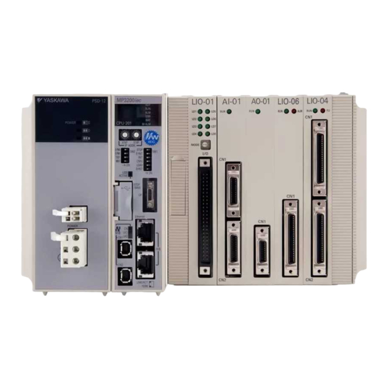
1.1 Combinations of MP2000/MP3000-series Products 1.1.2 Combinations of MP2000-series Products 1.1.2 Combinations of MP2000-series Products MP3200 MP3300 MP2000-series Abbreviation Description (CPU-201, (CPU-301, Product Name CPU-202) CPU-302) × × CPU-01 × × CPU-02 CPU+USB+CFIF × × CPU-03 CPU+Ethernet+CFIF × × CPU-04 CPU+Ethernet ... - Page 25 1.1 Combinations of MP2000/MP3000-series Products 1.1.2 Combinations of MP2000-series Products Continued from previous page. MP3200 MP3300 MP2000-series Abbreviation Description (CPU-201, (CPU-301, Product Name CPU-202) CPU-302) 16 inputs, 16 sinking outputs, and 1 pulse input LIO-01 channel 16 inputs, 16 sourcing outputs, and 1 channel ...
- Page 26 1.1 Combinations of MP2000/MP3000-series Products 1.1.2 Combinations of MP2000-series Products Continued from previous page. MP3200 MP3300 MP2000-series Abbreviation Description (CPU-201, (CPU-301, Product Name CPU-202) CPU-302) 64 inputs and IO2310 64 outputs 64 inputs and IO2330 64 outputs ...
-
Page 27: System Configuration Examples
Front cover for Battery supply or AC unused slot power supply You can expand the Main Rack by adding a Sub-CPU Module. Refer to the following manual for an MP3200 expansion example. MP3000 Series MP3200 User’s Manual (Manual No.: SIEP C880725 10) -
Page 28: Using The Mp3300
I/O Module with MECHATROLINK-III Communications Servomotor Servomotor Servomotor Up to 21 stations, including I/O (Up to 16 stations can be Servos.) Refer to the following manual for an MP3300 expansion example. MP3000 Series MP3300 User’s Manual (Manual No.: SIEP C880725 21) -
Page 29: Installation And Connections
Installation and Connections This chapter describes the installation and connections of MP3000-series Machine Controllers. MP3200 Installation ....2-2 2.1.1 Screw Mounting ......2-2 2.1.2 DIN Rail Mounting . -
Page 30: Mp3200 Installation
2.1 MP3200 Installation 2.1.1 Screw Mounting MP3200 Installation You can use either of the following methods to install an MP3200. • Screw mounting • DIN rail mounting Refer to the following appendix for more information on the installation and application require- ments. - Page 31 2.1 MP3200 Installation 2.1.1 Screw Mounting The installation procedure is as follows: Attach the Screw Mounting Attachment to the right end of the Controller. Screw Mounting Attachment In the same way as when mounting to DIN rail, use the rail locks to secure the Rack Support Bracket.
- Page 32 2.1 MP3200 Installation 2.1.1 Screw Mounting Use screws to secure the 4 places shown in the following figure. × Note: 1. Recommended screws: M4 14 mm min. 2. Use a screwdriver with a shaft that is at least 13 cm long. This completes the installation procedure.
- Page 33 2.1 MP3200 Installation 2.1.1 Screw Mounting Not Using a Sub-CPU Module on the Main Rack The installation procedure is as follows: Attach the Screw Mounting Attachment to the right end of the Controller. Screw Mounting Attachment...
- Page 34 2.1 MP3200 Installation 2.1.1 Screw Mounting Use screws to secure the 4 places shown in the following figure. × Note: 1. Recommended screws: M4 14 mm min. 2. Use a screwdriver with a shaft that is at least 13 cm long.
-
Page 35: Din Rail Mounting
2.1 MP3200 Installation 2.1.2 DIN Rail Mounting 2.1.2 DIN Rail Mounting This section describes how to install the Controller by mounting it on DIN rail. DIN Rail Types and the Spacer Various types of DIN rails are available with a 7-mm to 15-mm gap from the mounting surface as shown on the left in the following figure. - Page 36 2.1 MP3200 Installation 2.1.2 DIN Rail Mounting Carefully line up the DIN rail locks with the locking positions. Locking position Lock release position Place end plates on both sides of the MP3200 to secure it to the DIN rail. DIN rail End plate This completes the installation procedure.
-
Page 37: Connecting The Mp3200
2.1 MP3200 Installation 2.1.3 Connecting the MP3200 2.1.3 Connecting the MP3200 Use the following procedure to connect the MP3200. Before you connect the MP3200, install the Battery into the CPU Unit. Battery Installation (page 2-14) Note Remove the rubber cap from the connector on the Power Supply Unit. •... - Page 38 2.1 MP3200 Installation 2.1.3 Connecting the MP3200 Connect the Power Supply Unit and the CPU Unit from left to right in this order. Secure the connection by locking the slide locks at both the top and the bottom. 2-10...
-
Page 39: Installing Optional Modules
2.1 MP3200 Installation 2.1.4 Installing Optional Modules 2.1.4 Installing Optional Modules Use the following procedure to install Optional Modules. Hold the top and bottom of the Optional Module to be installed, line up the Module with the left side of the guide rail inside the option slot, and then insert the Module straight The FG bar inside and on the bottom may be damaged if the Module is not inserted along the guide rail. -
Page 40: Replacing And Adding Optional Modules
2.1 MP3200 Installation 2.1.5 Replacing and Adding Optional Modules 2.1.5 Replacing and Adding Optional Modules Use the following procedure to replace or add Optional Modules. Always create a backup before replacing or adding Optional Modules. Back up the program from the MP3000-series Controller to the PC using the MPE720. Important Turn OFF the power supply and disconnect all cables from the MP3000. - Page 41 2.1 MP3200 Installation 2.1.5 Replacing and Adding Optional Modules Pull the top of the Optional Module panel toward you and remove it. A notch on the Optional Module will be visible from the gap of the panel. Hook the round knob on the tool into the notch in the Optional Module.
-
Page 42: Battery Installation And Replacement
Lithium Content 0.4 g Number of Batteries Used 1 Note: This Battery is not available on the retail market. Order the Battery from Yaskawa Controls Co., Ltd. (The model number is JEPMC-OP3005.) Battery Installation The CPU Unit comes with one Battery. The Battery is not connected when the Unit is delivered. -
Page 43: 2.1.6 Battery Installation And Replacement
2.1 MP3200 Installation 2.1.6 Battery Installation and Replacement When Using the CPU-201 Confirm that the power supply to the MP3200 is turned OFF. Open the battery holder on the bottom of the CPU Unit. Securely connect the lead connector of the Battery to the connector in the CPU Unit. Press the connector back into the CPU Unit. - Page 44 2.1 MP3200 Installation 2.1.6 Battery Installation and Replacement Hold the connector, and while pressing it toward the CPU Unit’s internal circuit board (the board on the side of the clamp), move the Battery and the battery holder into the CPU Unit. Note: If this procedure is not followed, the battery leads may be pinched between the Battery and the circuit board, causing stress on the leads.
- Page 45 2.1 MP3200 Installation 2.1.6 Battery Installation and Replacement When Using the CPU-202 Confirm that the power supply to the MP3200 is turned OFF. Open the cover on the front of the CPU Unit. Securely connect the lead connector of the Battery to the connector in the CPU Unit. Move the Battery into the CPU Unit.
- Page 46 2.1 MP3200 Installation 2.1.6 Battery Installation and Replacement Battery Replacement CAUTION Suitable battery replacement must be performed and it must be performed only by an experienced technician. There is a risk of electrical shock, injury, or device damage. Replace the Battery only while power is supplied to the MP3200. Replacing the Battery while the power supply to the MP3200 is turned OFF may result in loss of the data stored in memory in the MP3200.
- Page 47 2.1 MP3200 Installation 2.1.6 Battery Installation and Replacement Remove the connector on the end of the Battery lead from the connector on the CPU Unit. Connector on CPU Unit Battery lead connector Remove the Battery from the battery holder. Battery holder Battery Insert the Replacement Battery into the battery holder.
- Page 48 2.1 MP3200 Installation 2.1.6 Battery Installation and Replacement Press the connector back into the CPU Unit. Press in. Hold the connector, and while pressing it toward the CPU Unit’s internal circuit board (the board on the side of the clamp), move the Battery and the battery holder into the CPU Unit.
- Page 49 2.1 MP3200 Installation 2.1.6 Battery Installation and Replacement When Using the CPU-202 Back up the programs and data stored in the MP3200. Note: The backup can be used to recover the data if the data accidentally gets deleted during Battery replacement.
- Page 50 2.1 MP3200 Installation 2.1.6 Battery Installation and Replacement Press the cable back into the CPU Unit. Close the cover on the CPU Unit and confirm that the BAT indicator on the CPU Unit is not lit. Lit. Not lit. This concludes the Battery replacement procedure. 2-22...
-
Page 51: Connecting A Rack Expansion Interface Unit
2.1 MP3200 Installation 2.1.7 Connecting a Rack Expansion Interface Unit 2.1.7 Connecting a Rack Expansion Interface Unit You can use a Rack Expansion Interface Unit to expand the system. This section describes the procedure to connect the Rack Expansion Interface Unit. Here, the Unit (EXU-001) on the Main Rack is used as an example. -
Page 52: Exioif Module Connections
2.1 MP3200 Installation 2.1.8 EXIOIF Module Connections Use the screws provided with the Rack Expansion Interface Unit to secure the Unit to the Power Supply Unit in the four places shown in the following figure. (The tightening torque is 0.32 N·m ±10%.) 2.1.8 EXIOIF Module Connections You can use an EXIOIF Module to add up to four Expansion Racks to the MP3000-series Base... - Page 53 2.1 MP3200 Installation 2.1.8 EXIOIF Module Connections The connection method for the external I/O connectors is shown in the following figure. EXIOIF Rack 1 EXIOIF Rack 2 EXIOIF Rack 3 EXIOIF Rack 4 Note: Attach the enclosed dust caps to the unused connectors ( in the above figure). Standard Cables Name Model...
-
Page 54: Mp3300 Installation
2.2 MP3300 Installation 2.2.1 Mounting with Screws MP3300 Installation You can use either of the following methods to install an MP3300 Controller. • Screw mounting • DIN rail mounting Refer to the following appendix for more information on the installation and application require- ments. - Page 55 2.2 MP3300 Installation 2.2.1 Mounting with Screws Using the MBU-304 Use the JEPMC-OP2300S-E Panel Mounting Attachment to install the Unit. The Screw Mounting Attachment is an optional product. You must purchase it separately. Note Panel Mounting Attachment 2-27...
-
Page 56: Din Rail Mounting
2.2 MP3300 Installation 2.2.2 DIN Rail Mounting 2.2.2 DIN Rail Mounting Carefully line up the DIN rail locks with the locking positions. Refer to the following section for details on installation. 2.1.2 DIN Rail Mounting on page 2-7 Using the MBU-303 Locking position Lock release position 2-28... - Page 57 2.2 MP3300 Installation 2.2.2 DIN Rail Mounting Using the MBU-304 Locking position Lock release position Removal You can remove the Controller by reversing the order of the mounting procedure. Note 2-29...
-
Page 58: Installing Optional Modules
2.2 MP3300 Installation 2.2.3 Installing Optional Modules 2.2.3 Installing Optional Modules Use the following procedure to install Optional Modules. Hold the top and bottom of the Optional Module to be installed, line up the Module with the left side of the guide rail inside the option slot, and then insert the Module straight The FG bar inside and on the bottom may be damaged if the Module is not inserted along the guide rail. -
Page 59: Replacing And Adding Optional Modules
2.2 MP3300 Installation 2.2.4 Replacing and Adding Optional Modules 2.2.4 Replacing and Adding Optional Modules Use the following procedure to replace or add Optional Modules. Always create a backup before replacing or adding Optional Modules. Back up the program from the MP3000-series Controller to the PC using the MPE720. Important Turn OFF the power supply and disconnect all cables from the MP3000. - Page 60 2.2 MP3300 Installation 2.2.4 Replacing and Adding Optional Modules Pull the top of the Optional Module panel toward you and remove it. A notch on the Optional Module will be visible from the gap with the panel. Hook the round knob on the battery cover into the notch in the Optional Module.
-
Page 61: Battery Installation And Replacement
Nominal Capacity 1,000 mAh Lithium Content 0.3 g Red lead Black lead Number of Batteries Used Note: This Battery is not available on the retail market. Order the Battery from Yaskawa Controls Co., Ltd. (The model number is JZSP-BA01.) 2-33... - Page 62 2.2 MP3300 Installation 2.2.5 Battery Installation and Replacement Battery Installation The CPU Module comes with one Battery. The Battery is not connected when the Module is delivered. Important CAUTION Suitable Battery installation must be performed and it must be performed only by an experienced technician.
- Page 63 2.2 MP3300 Installation 2.2.5 Battery Installation and Replacement Battery Replacement CAUTION Suitable Battery replacement must be performed and it must be performed only by an experienced technician. There is a risk of electrical shock, injury, or device damage. Replace the Battery only while power is supplied to the MP3300. Replacing the Battery while the power supply to the MP3300 is turned OFF may result in loss of the data stored in memory in the MP3300.
-
Page 64: Connecting An Exioif Module
2.2 MP3300 Installation 2.2.6 Connecting an EXIOIF Module Securely connect the lead connector of the replacement Battery to the connector in the Base Unit, and insert the replacement Battery into the battery holder. M-III Confirm that the BAT indicator of the CPU Module is not lit. Close the cover. -
Page 65: Connecting Devices
2.3 Connecting Devices 2.3.1 Part Names and Functions Connecting Devices This section explains how to connect devices to the MP3000-series Controllers. 2.3.1 Part Names and Functions The following figure shows the names and functions of the parts of the Machine Controller and the Servo Drive. - Page 66 2.3 Connecting Devices 2.3.1 Part Names and Functions MP3300 Status indicator Mode switches USB status indicators Display MECHATROLINK-III status indicators RLYOUT connector Power connector Ethernet connector Ethernet status indicator MECHATROLINK-III connectors 2-38...
- Page 67 2.3 Connecting Devices 2.3.1 Part Names and Functions Servo Drive SGDV-series SERVOPACK Reference-type SERVOPACK with MECHATROLINK-II Communications SERVOPACK with the Front Cover Open Rotary switch (SW1) This rotary switch is used to set the MECHATROLINK-II station address. Panel Display This seven-segment display indicates the status of the Servo.
- Page 68 2.3 Connecting Devices 2.3.1 Part Names and Functions Reference-type SERVOPACK with MECHATROLINK-III Communications SERVOPACK with the Front Cover Open Rotary switches (S1, S2) These switches are used to set the MECHATROLINK station address. Panel Display This seven-segment display indicates the status of the Servo.
-
Page 69: Connecting The Power Supply Connector
2.3 Connecting Devices 2.3.2 Connecting the Power Supply Connector 2.3.2 Connecting the Power Supply Connector This section describes how to connect the power supply connector. Power Connector Specifications, Pin Assignments, and Connection Method 100/200-VAC Power Supply The power supply for the Machine Controller is 100/200 VAC. Refer to the following figure for the connection methods. - Page 70 2.3 Connecting Devices 2.3.2 Connecting the Power Supply Connector Procedure to Make a 100/200-VAC Power Cable The power supply pins are contained in a removable connector. Use the following procedure to wire the power supply connector. Use a twisted-pair cable with a wire size of AWG28 to AWG13 (0.08 to 2.6 mm ) to connect the 100/200-VAC power supply to the power supply connector on the Controller.
- Page 71 2.3 Connecting Devices 2.3.2 Connecting the Power Supply Connector Cable for a 24-VDC Power Supply The power supply for the Machine Controller is 24 VDC. Refer to the following figure for the connection methods. Num- Connector Models Connector Name ber of Remarks Label...
-
Page 72: Connecting The Rly Out Connector
2.3 Connecting Devices 2.3.3 Connecting the RLY OUT Connector 2.3.3 Connecting the RLY OUT Connector The RLY OUT connector connects the status output terminal. It is an NO contact relay output. The RLY OUT connector is linked to the operation of the RDY indicator: The contacts close when the indicator lights, and they open when the indicator goes out. -
Page 73: Connecting The Power Supply And Other Devices
2.3 Connecting Devices 2.3.4 Connecting the Power Supply and Other Devices RLY OUT Connector Connection Example Refer to the following figure for an example of connecting the RLY OUT connector. RLY OUT Power RLY OUT output supply Normal operation: ON Error: OFF 24-VDC 24 VDC... - Page 74 2.3 Connecting Devices 2.3.4 Connecting the Power Supply and Other Devices Connect the devices using the MECHATROLINK-II or MECHATROLINK-III cables. MECHATROLINK-II cables To prevent communications errors, confirm that the connectors are properly inserted. • If more than one SERVOPACK is connected with MECHATROLINK-II Communications Cables, install a Terminator on the last SERVOPACK.
- Page 75 2.3 Connecting Devices 2.3.4 Connecting the Power Supply and Other Devices SERVOPACK MECHATROLINK-II MECHATROLINK-III − − − − 2-47...
-
Page 76: Usb Connector Connection
Confirm that the USB ACTIVE indicator lights. Refer to the following manual for details on the USB status indicator. MP3000 Series MP3200 User’s Manual (Manual No.: SIEP C880725 10) MP3000 Series MP3300 User’s Manual (Manual No.: SIEP C880725 21) 2-48... - Page 77 2.3 Connecting Devices 2.3.5 USB Connector Connection If you want to use a USB memory device for an extended period of time, lock the cover as shown in the following figure and then use the enclosed cable tie to secure the USB memory device into place.
- Page 78 2.3 Connecting Devices 2.3.5 USB Connector Connection Removing the USB Memory Device Use the STOP/SAVE switch to remove USB memory. After you lightly press and release this switch, the USB memory can be safely removed when the USB status indicator changes from flashing to not lit. STOP/SAVE switch Open the cover.
-
Page 79: Machine Controller Setup
Machine Controller Setup This chapter provides the procedures for setting up a Machine Controller using the MPE720. The Flow of the Setup ....3-3 MPE720 Installation . - Page 80 Test Run ......3-52 3.7.1 Test Run .......3-52 3.7.2 Starting the Test Run and Selecting the Axis .
-
Page 81: The Flow Of The Setup
3.1 The Flow of the Setup The Flow of the Setup The following flowchart shows the setup procedures. 3.2 MPE720 Installation on page 3-4 MPE720 Installation Creating a Project File 3.3 Creating a Project File on page 3-7 Self Configuration 3.4 Self Configuration on page 3-10 Placing the MPE720 Online 3.5 Placing the MPE720 Online on page 3-14... -
Page 82: Mpe720 Installation
3.2 MPE720 Installation MPE720 Installation Use the following procedure to install the MPE720. Refer to the following brochure or the catalog for details on the system requirements of the MPE720. System Integrated Engineering Tool MPE720 Ver.7 (Manual No.: KAEP C880761 00) What Is the MPE720? It is the Engineering Tool that you use to design and maintain Machine Controller applications. - Page 83 3.2 MPE720 Installation The License Agreement will be displayed. Read the agreement, select the I accept the terms of the license agreement Option, and then click the Next Button. Enter the user name, company name and serial number (on the DVD-ROM package), and then click the Next Button.
- Page 84 3.2 MPE720 Installation Click the Install Button. When the MPE720 installation is completed, the following dialog box will be displayed.
-
Page 85: Creating A Project File
3.3 Creating a Project File 3.3.1 Project Files Creating a Project File This section gives the procedure for creating a project file. 3.3.1 Project Files A project file is the application file for MPE720 version 7. It includes the following information. •... -
Page 86: Creating A Project File
Note: The file name cannot contain any of the following characters: / \ :* " < > | Select the file extension for the project file from the list of possible extensions. Save as type MP3000 Series: .YMW7 Select the series of the Machine Controller to use. Series ... -
Page 87: Setting A Project Password
3.3 Creating a Project File 3.3.3 Setting a Project Password Click the Create Button. After the Create/Open Project File message is displayed, the project file is created in the specified folder and the created project file is displayed in the System Pane. After you create a project file, you can perform program file operation in the Ladder and Motion Panes. -
Page 88: Self Configuration
3.4 Self Configuration 3.4.1 Self Configuration Using the DIP Switch Self Configuration This section gives the self configuration procedures. Self configuration is a feature that automatically recognizes all the Optional Modules that are installed in the Machine Controller and all the slave devices that are connected via the MECHA- TROLINK connector (such as Servo Drives), and creates the module configuration definition files based on that information. - Page 89 3.4 Self Configuration 3.4.1 Self Configuration Using the DIP Switch Turn OFF the INIT and CNFG pins on the DIP switch (SW1) on the MP3000-series Con- troller. STOP E-INIT INIT CNFG LOAD D-RST 1. INIT Pin on the DIP Switch and RAM Data If the power supply is turned ON while the INIT pin on the Machine Controller DIP switch is turned ON, the data stored in the RAM will be deleted.
-
Page 90: Self Configuration Using The Mpe720
3.4 Self Configuration 3.4.2 Self Configuration Using the MPE720 Turn OFF the INIT and CNFG pins on the DIP switches (mode switches) on the CPU Module. 1. INIT Pin on the DIP Switch and RAM Data If the power supply is turned OFF and ON again when the INIT pin on the Machine Controller SW1 DIP switch is turned ON, the data in RAM will be cleared. - Page 91 Refer to the following manual for details and for the rest of the procedure. MP2000/MP3000 Series Engineering Tool MPE720 Version 7 User’s Manual (Manual No.: SIEP C880761 03) Refer to the above manual for the procedure to perform self configuration for only specified Modules.
-
Page 92: Placing The Mpe720 Online
3.5 Placing the MPE720 Online 3.5.1 Preparing the Ethernet Connection Placing the MPE720 Online This section describes how to go online. Going online refers to connecting the MPE720 to the Machine Controller. Term 3.5.1 Preparing the Ethernet Connection Use the following procedure to prepare the Ethernet connection. Use an Ethernet cable to connect the Ethernet connector on the Machine Controller to the LAN connector on the PC. - Page 93 3.5 Placing the MPE720 Online 3.5.1 Preparing the Ethernet Connection Select the Use the following IP address Option, and enter the following data. IP address =192.168.1.2 Subnet mask = 255.255.255.0 Do not use the same IP address as the IP address of the Machine Controller. The default IP address of the Controller is 192.168.1.1.
-
Page 94: Going Online
3.5 Placing the MPE720 Online 3.5.2 Going Online 3.5.2 Going Online Use the following procedure to go online. Double-click the MPE720 Icon on the desktop. − − If there is no icon on the Desktop, then select All Programs YE_Applications MPE720 Ver.7 from the Windows Start Menu. - Page 95 3.5 Placing the MPE720 Online 3.5.2 Going Online The connection was successfully established if the MPE720 window appears with “Online” displayed in it. Verify going online here. You can also connect by using a serial port. Information Refer to the manuals of the Machine Controller for details. 3-17...
-
Page 96: Project Link Connection
3.5 Placing the MPE720 Online 3.5.3 Project Link Connection 3.5.3 Project Link Connection This section gives the procedure to create a project link connection. A project link connection refers to connecting the MPE720 that has an open project file to the Machine Controller. -
Page 97: Device-Specific Settings
3.6 Device-specific Settings 3.6.1 Data That Is Automatically Updated during Self Configuration Device-specific Settings This section describes the data that is automatically updated during self configuration, and the data that is changed by the user. 3.6.1 Data That Is Automatically Updated during Self Configuration Use the following procedure to confirm the results of self configuration to make sure that the Modules are properly assigned to the slots. - Page 98 3.6 Device-specific Settings 3.6.1 Data That Is Automatically Updated during Self Configuration Module Configuration Definition Tab Page Details The following table describes the items that are displayed in the Module Configuration Defini- tion Tab Page. ...
- Page 99 3.6 Device-specific Settings 3.6.1 Data That Is Automatically Updated during Self Configuration Precautions When Setting the Parameters • Always save all settings to the flash memory after changing them. • When changing the settings, be careful not to set register numbers that overlap with other Note Modules.
-
Page 100: Detailed Module Settings
3.6 Device-specific Settings 3.6.2 Detailed Module Settings 3.6.2 Detailed Module Settings This section describes the following settings: • Communications settings • MECHATROLINK communications settings • Motion control settings Communications Settings Double-click slot 2 to display details on the Module. Connecting to the Host Device We recommend that you use an Ethernet connection to connect the Machine Controller to the host device. - Page 101 3.6 Device-specific Settings 3.6.2 Detailed Module Settings Using the MPE720 for Easy Connection Click slot 2 on the Module Configuration Tab Page. The following dialog box will be displayed. Click the Easy setting Button in the Mes- sage Communication Area. 3-23...
- Page 102 3.6 Device-specific Settings 3.6.2 Detailed Module Settings The following dialog box will be displayed. Select the communications protocol type from the list, and click the OK Button. This concludes the setting procedure. Refer to the following manual for details. MP3000-series Motion Control User’s Manual (Manual No.: SIEP C880725 11) 3-24...
- Page 103 3.6 Device-specific Settings 3.6.2 Detailed Module Settings MECHATROLINK Communications Settings Double-click SVC32 at slot 3 to display the MECHATROLINK Communications Definition Dia- log Box. The MECHATROLINK Communications Definition Dialog Box has four tabs: Transmission Parameters, Link Assignment, I/O Map, and Status. Click a tab to view the tab page. ...
- Page 104 3.6 Device-specific Settings 3.6.2 Detailed Module Settings Slave Synchronization Settings (Slave CPU Synchronization) Information Slave CPU synchronization is used for configurations with master and slave Machine Control- lers that have CPU Units with built-in SVC32 function modules in order to synchronize the high-speed scan cycle of the master and slave Machine Controllers.
- Page 105 3.6 Device-specific Settings 3.6.2 Detailed Module Settings Link Assignment Tab Page The Link Assignment Tab Page displays the assignment settings for all slave devices that were detected during self-configuration (MECHATROLINK-connected devices, such as SERVO- PACKs or distributed I/O). ...
- Page 106 The following figure shows an example of how to set extended addresses. Set the extended address in order starting from 00 hex: 01 hex, 02 hex, etc. VENDOR Set the vendor name of the device. • Settings: Yaskawa Electric Co., **** Vendor 3-28...
- Page 107 3.6 Device-specific Settings 3.6.2 Detailed Module Settings DEVICE Set the slave model. • Link Assignment Model Details The relationship between the model displayed under DEVICE and its corresponding profile is shown below. If you manually assign a link, be sure that the actual device connected to the SVC Module is the same as the one that is displayed under DEVICE on the Link Assignment Tab Page.
- Page 108 3.6 Device-specific Settings 3.6.2 Detailed Module Settings SIZE Set the input and output sizes in words. These settings are disabled if the profile is set to Standard Servo. • Setting range: 0 to 32 SCAN Set the scan in which the input and output is performed. This setting is always set to High if the profile is set to Standard Servo.
- Page 109 3.6 Device-specific Settings 3.6.2 Detailed Module Settings Motion Control Settings Use the following procedure to display the SVC Definition Tab Page. Select View − Work Space from the menu bar. The Work Space Pane is displayed on the left side of the window. Click the Expand [+] Button beside each item in the Work Space Pane to display motion parameters as shown below.
- Page 110 3.6 Device-specific Settings 3.6.2 Detailed Module Settings Double-click the motion parameter to set or monitor. The Axis Display Selection Dialog Box (“Display in axis selected”) will be displayed. Select the axis to set or monitor, and then click the OK Button. The SVC Definition Tab Page for the selected motion parameters will be displayed.
- Page 111 3.6 Device-specific Settings 3.6.2 Detailed Module Settings Setting the Setting Parameters The values of these parameters are normally set from a ladder program. However, values for setting parameters that do not need to be set from a ladder program can be specified on this tab page and saved from here.
- Page 112 3.6 Device-specific Settings 3.6.2 Detailed Module Settings Setting the SERVOPACK Parameters The settings of the parameters can be prepared inside the CPU Unit of the Controller while it is offline. When the Controller and the SERVOPACK are connected, you can transfer these values to the SERVOPACK in one batch.
-
Page 113: Parameters Written During Self Configuration
3.6 Device-specific Settings 3.6.3 Parameters Written during Self Configuration 3.6.3 Parameters Written during Self Configuration The fixed values in the Machine Controller are written to the SERVOPACK EEPROM or RAM during self-configuration as shown below. The SERVOPACK parameters are also written to the Machine Controller's setting parameters. -
Page 114: Setting Machine-Specific Motion Parameters
3.6 Device-specific Settings 3.6.4 Setting Machine-specific Motion Parameters 3.6.4 Setting Machine-specific Motion Parameters Set the following eight motion parameters according to the machine’s specifications to ensure correct motion control. • Reference Unit • Electronic Gear • Axis Selection • Position Reference •... - Page 115 3.6 Device-specific Settings 3.6.4 Setting Machine-specific Motion Parameters Starting the Axis Setup Wizard To start the Axis Setup Wizard, double-click Axis Setup Wizard under Axis configuration in the System Pane. Alternatively, you can click the Axis Setup Wizard Button on the Start Tab Page. 3-37...
- Page 116 3.6 Device-specific Settings 3.6.4 Setting Machine-specific Motion Parameters Axis Setup Wizard Details Axis Setup Wizard This wizard sets up individual axes for SERVOPACKs that are connected to a MECHATROLINK network. Item Description Axis Monitor...
- Page 117 3.6 Device-specific Settings 3.6.4 Setting Machine-specific Motion Parameters Axis Selection The information that is assigned in the Module configuration definition will be displayed. Select the axis to set up. Only the selected single axis can be used in the Axis Setup Wizard. To set up other axes, Information click the Axis Button and select the axis in the Axis Selection Dialog Box.
- Page 118 3.6 Device-specific Settings 3.6.4 Setting Machine-specific Motion Parameters Fixed Parameter Setting The fixed parameters of the Machine Controller are set according to the machine. Item Description Tool Bar Refer to Tool Bar (1) in the Axis Setup Wizard Dialog Box. ...
- Page 119 3.6 Device-specific Settings 3.6.4 Setting Machine-specific Motion Parameters Reference Unit The motion control reference unit can be set to the pulse, mm, deg, inch, or μm. The reference unit is specified in motion fixed parameter No. 4 (Reference Unit Selection). The minimum refer- ence unit is determined by the setting of motion fixed parameter No.
- Page 120 3.6 Device-specific Settings 3.6.4 Setting Machine-specific Motion Parameters The following examples show the settings for a ball screw and rotary table as loads. • Ball Screw • Rotary Table 3-42...
- Page 121 3.6 Device-specific Settings 3.6.4 Setting Machine-specific Motion Parameters • Belt and Pulley Item Description Select one of the following five reference units. 0: pulse, 1: mm, 2: deg, 3: inch, or 4: μm Reference unit selection When the Reference Unit Selection parameter is set to 0 (pulse), the settings from (2) onward are disabled.
- Page 122 3.6 Device-specific Settings 3.6.4 Setting Machine-specific Motion Parameters Axis Type Setting This dialog box is used to set the motor type and the axis type. There are two types of position control: finite-length axis position control for round-trip opera- tion and other tasks that are performed only within a specified range, and infinite-length axis position control that is used for rotation in one direction only.
- Page 123 3.6 Device-specific Settings 3.6.4 Setting Machine-specific Motion Parameters Absolute Position Detection Setting Set the maximum number of absolute encoder rotations for simple absolute infinite axis posi- tion management. The following parameters can be set after you set absolute position detection. Fixed Parameter No.
- Page 124 3.6 Device-specific Settings 3.6.4 Setting Machine-specific Motion Parameters (Fixed parameter No. 38: Maximum Number of Absolute Encoder Rotations = Integer (Remainder = 0) Reset rotations The following formulas give the value of the reset rotations. The formula depends on whether the reference unit is set to the pulse or to one of the following: mm, deg, or inch.
- Page 125 3.6 Device-specific Settings 3.6.4 Setting Machine-specific Motion Parameters Fixed Parameter Saving This section describes how to save the fixed parameter settings. Click the Axis Setup Wizard Button, click the Fixed Parameter Setting Button, and then click the Fixed Parameter Saving Button to display the following dialog box. Next, the Reflect SERVOPACK Parameter Dialog Box will be displayed.
-
Page 126: Setting The Scan Times
3.6 Device-specific Settings 3.6.5 Setting the Scan Times 3.6.5 Setting the Scan Times This section describes how to set the scan times for the high-speed and low-speed scans. Select Setup and then Scan Time Setting from the item tree of the Environment Setting Dia- log Box. - Page 127 The alarm is reported in the M-III Restrictions Error Bit (SB00041D) in the CPU Error Sta- tus System Register. Refer to the following manuals for details. MP3000 Series MP3200 User’s Manual (Manual No.: SIEP C880725 10) Restrictions Imposed by Σ-V SERVOPACKs Connected to the SVC or SVC32 Module in the CPU Unit/CPU Module The specifications of MECHATROLINK-III Σ-V-series SERVOPACKs impose the following...
- Page 128 3.6 Device-specific Settings 3.6.5 Setting the Scan Times I/O Processing If the high-speed scan time is set to at least 0.5 ms, the I/O service (I/O processing) of the MP2000 Optional Module will be performed every scan. If the high-speed scan time is set to less than 0.5 ms (0.125 ms or 0.250 ms), the I/O service (I/O processing) of the MP2000 Optional Module will be performed at the filtered basic cycle of 0.5 ms.
- Page 129 3.6 Device-specific Settings 3.6.5 Setting the Scan Times Example: High-speed Scan = 0.125 ms 0.5 ms 0.125 ms High-speed scan Basic cycle (0.5 ms) Reference issued at (1) Reference issued at (9) Reference issued at (5) MP2000 Optional...
-
Page 130: Test Run
3.7 Test Run 3.7.1 Test Run Test Run This section describes the features of the test run. 3.7.1 Test Run The test run checks whether the references issued by the Machine Controller correctly drive the SERVOPACK axis. You can perform the following operations for a test run from the Test Run Dialog Box. •... -
Page 131: Starting The Test Run And Selecting The Axis
3.7 Test Run 3.7.2 Starting the Test Run and Selecting the Axis 3.7.2 Starting the Test Run and Selecting the Axis Open the Test Run Dialog Box and specify the SERVOPACK axis to test. Use the following pro- cedure to set the axis. Double-click Test run under Axis configuration in the System Pane. - Page 132 3.7 Test Run 3.7.2 Starting the Test Run and Selecting the Axis The following message will be displayed. Click the Yes Button. The label of the selected axis will be displayed on the right of the Axis... Button in the Test Run Dialog Box. The Test Run can be performed only on the selected axis.
-
Page 133: Test Run Dialog Box Details
3.7 Test Run 3.7.3 Test Run Dialog Box Details 3.7.3 Test Run Dialog Box Details This section provides a detailed description of the Test Run Dialog Box. You can select jogging or stepping by clicking the tabs. Jogging Stepping ... -
Page 134: Creating User Programs
Creating User Programs This chapter describes the types of user programs and describes how to create and write them to the Controller. User Program Types and Execution Timing 4-3 4.1.1 Ladder Programs ......4-3 4.1.2 Motion Programs . - Page 135 Data Transfer without Using the MPE720 . . . 4-71 4.6.1 Using USB Memory ..... .4-71 4.6.2 Using the MPLoader Ver.4 ....4-74 4.6.3 Using the MPLoad Maker .
-
Page 136: User Program Types And Execution Timing
4.1 User Program Types and Execution Timing 4.1.1 Ladder Programs User Program Types and Execution Timing There are three types of user programs: • Ladder programs • Motion programs • Sequence programs This section describes these programs. 4.1.1 Ladder Programs Ladder programs are managed as drawings (ladder diagrams) that are identified by their draw- ing numbers (DWG numbers). - Page 137 4.1 User Program Types and Execution Timing 4.1.1 Ladder Programs Hierarchical Configuration There are four types of ladder drawings: parent drawings, child drawings, grandchild drawings, and operation error drawings. • Parent Drawings These drawings are automatically executed by the system program when the execution con- ditions are met.
- Page 138 4.1 User Program Types and Execution Timing 4.1.1 Ladder Programs The breakdown of the number of ladder drawings in each category is given in the following table. Number of Drawings Drawings DWG.A DWG.I DWG.H DWG.L Parent Drawings Operation Error Drawings Child Drawings Total of 62 max.
- Page 139 4.1 User Program Types and Execution Timing 4.1.1 Ladder Programs Execution Processing of Drawings The drawings are executed by calling them from the top to the bottom, following the hierarchy of the drawings. The following figure illustrates the execution processing of a high-speed scan drawing (DWG.H).
- Page 140 4.1 User Program Types and Execution Timing 4.1.1 Ladder Programs Scheduling the Execution of High-speed and Low-speed Scan Process Drawings High-speed scan process drawings (DWG.H) and low-speed scan process drawings (DWG.L) cannot be executed at the same time. DWG.L drawings are executed during the idle time of DWG.H drawings.
- Page 141 4.1 User Program Types and Execution Timing 4.1.1 Ladder Programs Setting Value: Enter the scan time settings. Current Value: A value of 0.0 ms is displayed when the MPE720 is offline. Otherwise, the actual processing times for the scans are displayed. Maximum Value: The maximum processing time for the scan is displayed.
- Page 142 4.1 User Program Types and Execution Timing 4.1.1 Ladder Programs High-speed Drawing Operation Mode Settings The high-speed drawing operation mode is the mode that is set for DWG.H drawings. If no DWG.I drawings are used, select the high-speed mode. This optimizes the processing of DWG.H drawings.
- Page 143 4.1 User Program Types and Execution Timing 4.1.1 Ladder Programs Perform the following procedure with MPE720 version 7 to set the high-speed drawing opera- tion mode. − Select File Environment Settings from the menu bar. Alternatively, click the System Setting Icon on the My Tool View of the Start Tab Page. The Environment Setting Dialog Box is displayed.
- Page 144 4.1 User Program Types and Execution Timing 4.1.1 Ladder Programs Functions Functions are executed when they are called from a parent, child, or grandchild drawing with the FUNC instruction. Functions can be freely called from any drawing. The same function can be called simultane- ously from different types of drawings or different levels of drawings.
-
Page 145: Motion Programs
4.1 User Program Types and Execution Timing 4.1.2 Motion Programs 4.1.2 Motion Programs A motion program is a program that is written in a text-based motion language. There are two types of motion programs. Designation Type Features Number of Programs Method •... - Page 146 4.1 User Program Types and Execution Timing 4.1.2 Motion Programs Motion Program Execution Motion programs are called with an MSEE instruction from a ladder program in an H drawing. You can also register the motion program in the M-EXECUTOR (Motion Executor) to call it. Refer to the following section for details.
- Page 147 4.1 User Program Types and Execution Timing 4.1.2 Motion Programs Specifying Motion Programs There are two methods that you can use to specify motion programs. • Calling the motion program by specifying it directly • Calling the motion program by specifying it indirectly These two methods are described below.
- Page 148 4.1 User Program Types and Execution Timing 4.1.2 Motion Programs Work Registers Work registers are used to set and monitor motion programs. The first work register for a motion program that is called with an MSEE instruction is specified in the MSEE instruction in the ladder program. The following figure shows the structure of the work registers.
- Page 149 4.1 User Program Types and Execution Timing 4.1.2 Motion Programs Control Signals To control the execution of a motion program, you must input program control signals (Request for Start of Program Operation, or Request for Stop of Program, etc.). The following table describes the control signals for motion programs.
- Page 150 4.1 User Program Types and Execution Timing 4.1.2 Motion Programs Motion Program Control Signals Timing Chart Timing chart examples for axis operations and status flags after a control signal is input are provided below. • Request for Start of Program Operation Control signal: Request for Start of Program Operation Status flag: Program Executing...
- Page 151 4.1 User Program Types and Execution Timing 4.1.2 Motion Programs • If a Motion Program Alarm Occurs Control signal: Request for Start of Program Operation Control signal: Program Reset and Alarm Reset Request Status flag: Program Executing Status flag: Program Alarm 1 scan* Axis operation: Pulse distribution for Interpolation instruction...
- Page 152 4.1 User Program Types and Execution Timing 4.1.2 Motion Programs Using the Work Registers The work registers for motion program are used differently depending on whether the motion program is called from a ladder program using an MSEE instruction, or the motion program is registered in the M-EXECUTOR program execution definitions.
- Page 153 4.1 User Program Types and Execution Timing 4.1.2 Motion Programs Ladder Program Example 4-20...
- Page 154 4.1 User Program Types and Execution Timing 4.1.2 Motion Programs Monitoring the Execution Information on the Motion Pro- gram with S Registers You can monitor execution information on the motion program with the S registers (SW03200 to SW05119 and SW08192 to SW09215). The execution information is monitored differently, depending on whether the motion program is called from a ladder program with an MSEE instruction, or the motion program is registered in the M-EXECUTOR program execution definitions.
- Page 155 4.1 User Program Types and Execution Timing 4.1.2 Motion Programs Register Ranges for Motion Program Execution Information Number of Program Using Work Number 1 SW03200 Number of Program Using Work Number 2 SW03201 Number of Program Using Work Number 3 SW03202 Number of Program Using Work Number 4 SW03203...
- Page 156 4.1 User Program Types and Execution Timing 4.1.2 Motion Programs Contents of Work n Program Information Work n Program Information Program Status Program Control Signals Active Program Numbers Current Block Number Parallel Fork 0 Information Alarm Code Parallel Fork 1 Information Parallel Fork 2 Information Parallel Fork 3 Information Parallel Fork 4 Information...
-
Page 157: Sequence Programs
4.1 User Program Types and Execution Timing 4.1.3 Sequence Programs 4.1.3 Sequence Programs A sequence program is written in a text-based motion language. There are two types of sequence programs. Designation Type Features Number of Programs Method Main programs are called from You can create up to 512 motion SPM... - Page 158 4.1 User Program Types and Execution Timing 4.1.3 Sequence Programs Specifying Sequence Programs Sequence programs must be specified directly. Indirect designations cannot be used. Specify the program number of the sequence program to execute (SPM). Sequence Program SPM001 M-EXECUTOR Program Execution Definitions IF MW000<32767;...
-
Page 159: The M-Executor
A sequence program can be used in place of a ladder program. Refer to the following manual for instructions that can be used in sequence programs. MP3000 Series Motion Programming Manual (Manual No.: SIEP C880725 14) The execution of a sequence program is completed in one scan. - Page 160 4.1 User Program Types and Execution Timing 4.1.4 The M-EXECUTOR Program Control Methods You can use the following control methods for the programs that are registered in the M-EXEC- UTOR: Item Motion Programs Sequence Programs Startup: Event execution Execution method Sequential execution H scan: Scan execution L scan: Scan execution...
- Page 161 4.1 User Program Types and Execution Timing 4.1.4 The M-EXECUTOR Initializing the M-EXECUTOR Use the following procedure to initialize the M-EXECUTOR. Click the Module Configuration Icon from the Start Tab Page. The Module Configuration Tab Page will be displayed as shown below. 4-28...
- Page 162 4.1 User Program Types and Execution Timing 4.1.4 The M-EXECUTOR Double-click the UNDEFINED cell in row 05 of the Function Module/Slave Column. The Function Module Dialog Box will be displayed. Select M-EXECUTOR and click the OK Button. 4-29...
- Page 163 4.1 User Program Types and Execution Timing 4.1.4 The M-EXECUTOR Verify that M-EXECUTOR is displayed in row 05, and double-click M-EXECUTOR. Information If M-EXECUTOR is displayed, then the M-EXECUTOR is properly assigned. The M-EXECUTOR Definition Dialog Box will be displayed. 4-30...
- Page 164 4.1 User Program Types and Execution Timing 4.1.4 The M-EXECUTOR Click the OK Button. The Detail Definition Dialog Box will be displayed. Select File - Save from the toolbar. The M-EXECUTOR definitions will be saved. Verify that Driving is displayed in the Status cell of the M-EXECUTOR row in the Module Configuration Definition Tab Page.
- Page 165 4.1 User Program Types and Execution Timing 4.1.4 The M-EXECUTOR M-EXECUTOR Detail Settings The detailed settings for the M-EXECUTOR are performed on the Module Configuration Tab Page and the Detail Definition Dialog Box. This section provides the procedures to display this tab page and dialog box, and describes their contents.
- Page 166 4.1 User Program Types and Execution Timing 4.1.4 The M-EXECUTOR Continued from previous page. Item Display/Setting Item Editing Not used. Not possi- Disabled “----” is always displayed. Displays the range of registers that is used as the I/O area. •...
- Page 167 4.1 User Program Types and Execution Timing 4.1.4 The M-EXECUTOR Program Definition Tab Page Register the motion or sequence programs to execute. This section describes the items that are displayed on the Program Definition Tab Page. ...
- Page 168 If the execution type is set to a motion program, the range of the execution monitor registers (S registers) will be displayed. Refer to the following manual for details on the execution mon- itor registers. MP3000 Series Motion Programming Manual (Manual No.: SIEP C880725 14) 4-35...
- Page 169 4.1 User Program Types and Execution Timing 4.1.4 The M-EXECUTOR Allocation Control Register Tab Page This tab page is used to assign registers. This section describes the items that are displayed on the Allocation Control Register Tab Page. ...
- Page 170 Double-click the Status or the Control signal cell to display the Detail Dialog Box. This dialog box is used to verify the status and the control signals. • Status • Control Signals Creating Motion Programs Refer to the following manual for details. MP3000 Series Motion Programming Manual (Manual No.: SIEP C880725 14) 4-37...
- Page 171 You can also use the Task Allocation Dialog Box to change the settings. Refer to the Information following manual for details. MP3000 Series Motion Programming Manual (Manual No.: SIEP C880725 14) Check that the settings match the contents of the Allocation Control Register Tab Page, and then click the Set Button.
- Page 172 4.1 User Program Types and Execution Timing 4.1.4 The M-EXECUTOR Execution Scheduling Programs that are registered in the M-EXECUTOR are executed in the order of their priority lev- els (execution types). Programs that are registered in the M-EXECUTOR are executed immediately before processing the ladder programs.
- Page 173 4.1 User Program Types and Execution Timing 4.1.4 The M-EXECUTOR The following is an execution example. • M-EXECUTOR Program Execution Definitions Sequence Program Execution Example Example The following figure shows an example of the sequence programs registered in the M- EXECUTOR.
-
Page 174: Registers
4.1 User Program Types and Execution Timing 4.1.5 Registers 4.1.5 Registers Registers are areas that store data within the Machine Controller. Variables are registers with labels (variable names). There are two kinds of registers: global registers that are shared between all programs, and local registered that are used only by a specific program. - Page 175 4.1 User Program Types and Execution Timing 4.1.5 Registers Local Registers Local registers can be used within each specific drawing. These registers cannot be shared by other drawings. Local registers are stored in the program memory for each drawing. Ladder Program Conceptual Diagram Child drawing User function Parent drawing...
- Page 176 4.1 User Program Types and Execution Timing 4.1.5 Registers Register Types This section describes global and local registers. Global Registers Global registers are shared by ladder programs, user functions, motion programs, and sequence programs. In other words, the operation results of a ladder program can be used by other user functions, motion programs, or sequence programs.
- Page 177 4.1 User Program Types and Execution Timing 4.1.5 Registers Local Registers Local registers are valid within only one specific program. The local registers in other programs cannot be accessed. You specify the usable range from the MPE720. Designation Type Name Description Features...
- Page 178 4.1 User Program Types and Execution Timing 4.1.5 Registers Local Registers within a User Function In addition to # registers and D registers, there are local registers that can be used only within individual user functions. Type Name Designation Methods Description These registers are used for inputs to functions.
- Page 179 4.1 User Program Types and Execution Timing 4.1.5 Registers • Setting the D Register Clear When Start Option Select File - Environment Setting from the MPE720 Version 7 Window. Select Setup - System Setting. Select Enable or Disable for the D Register Clear when Start option. Disable: The initial values will be uncertain.
- Page 180 4.1 User Program Types and Execution Timing 4.1.5 Registers Data Types There are different data types that you can use depending on the purpose of the application: bit, integer, double-length integer, quadruple-length integer, real number, double-precision real number, and address. Symbol Data Type Range of Values...
- Page 181 4.1 User Program Types and Execution Timing 4.1.5 Registers Data Types and Register Designations An extra digit that specifies the bit (3) is appended to the end of the register address (0000100). One word is allocated for each register address. Integer data [MB00001003] Bit data...
- Page 182 4.1 User Program Types and Execution Timing 4.1.5 Registers Precautions for Operations Using Different Data Types If you perform an operation using different data types, be aware that the results will be different depending on the data type of the storage register, as described below. •...
- Page 183 4.1 User Program Types and Execution Timing 4.1.5 Registers The data is little endian, as shown in the following example. Information • MB00001006 MB00001006 MW0000100 • MW0000100 = 1234 hex MW0000100 1234 hex • ML0000100 = 12345678 hex MW0000100 5678 hex ML0000100 MW0000101 1234 hex...
- Page 184 4.1 User Program Types and Execution Timing 4.1.5 Registers Double-length Integer Upper Word Lower Word MW0000001 MW0000000 If j = 0, ML0000000j is ML0000000. MW0000002 MW0000001 If j = 1, ML0000000j is ML0000001. Upper Word Lower Word Real Number MW0000001 MW0000000 If j = 0, MF0000000j is MF0000000.
- Page 185 4.1 User Program Types and Execution Timing 4.1.5 Registers Array Registers ([ ]) Array registers are used to modify register addresses. They are used to handle register addresses as variables. As with indices, an offset can be added to the register address. ...
-
Page 186: Creating Ladder Programs
4.2 Creating Ladder Programs Creating Ladder Programs Use the following procedure to create a ladder program. The following example shows how to create a high-speed program, but low-speed and startup programs can be created in essentially the same way. Note Select Programming - Ladder program in the Launcher. - Page 187 4.2 Creating Ladder Programs Enter the ladder program. Ladder programs are entered by inserting rungs, then instructions, and finally parameters for the instructions. Refer to the following section for details. Ladder Program Creation Example (page 4-54) − While displaying the ladder program, select Compile Compile from the menu bar to compile the program.
- Page 188 MB000000 will be displayed for the NO Contact instruction. Note: The type of register and data you can use depend on the actual instruction. Refer to the following manual for details on each instruction. MP3000 Series Ladder Programming Manual (Manual No.: SIEP C880725 13) 4-55...
- Page 189 4.2 Creating Ladder Programs To insert a comment, right-click the tab with the row number, and select Insert Rung Information Comment. Repeat steps 1 to 4 until you have entered the entire ladder program. The following example shows a ladder program and its timing chart. <Ladder Program Example>...
-
Page 190: Creating Motion Programs
4.3 Creating Motion Programs 4.3.1 Creating a Group Definition Creating Motion Programs This section describes how to create motion main programs and motion subprograms. 4.3.1 Creating a Group Definition Before creating a motion program, we have to group the axes together as required by the machine configuration. -
Page 191: Creating A Motion Main Program
4.3.2 Creating a Motion Main Program Click the OK Button. Refer to the following manual for details on group definitions. MP3000 Series Motion Programming Manual (Manual No.: SIEP C880725 14) 4.3.2 Creating a Motion Main Program Use the following procedure to create a motion main program. - Page 192 4.3 Creating Motion Programs 4.3.2 Creating a Motion Main Program Edit the motion program. Use the instruction input assistance feature to insert an INC instruction and a MOV instruction into the motion program. The motion instruction assistance feature is used by right-clicking on the Motion Editor Tab Page. •...
-
Page 193: Creating A Motion Subprogram
4.3 Creating Motion Programs 4.3.3 Creating a Motion Subprogram 4.3.3 Creating a Motion Subprogram Use the following procedure to create a motion subprogram. Start the Motion Editor. Expand the tree structure in the Motion Pane. Right-click Sub program, and select New. - Page 194 4.3 Creating Motion Programs 4.3.3 Creating a Motion Subprogram Select Compile - Compile from the menu bar to compile the program. When the compilation is completed, the motion program is saved automatically. If an error was displayed in the Error List Dialog Box during compilation, the motion program will not be saved.
-
Page 195: Creating A Sequence Program
4.4 Creating a Sequence Program 4.4.1 Creating a Sequence Main Program Creating a Sequence Program This section describes how to create sequence main programs and sequence subprograms. 4.4.1 Creating a Sequence Main Program Use the following procedure to create a sequence main program. Start the Motion Editor. -
Page 196: Creating A Sequence Subprogram
4.4 Creating a Sequence Program 4.4.2 Creating a Sequence Subprogram Select Compile - Compile from the menu bar to compile the program. When the compilation is finished, the motion program will be saved automatically. If an error occurs during compilation, the motion program will not be saved. Important 4.4.2 Creating a Sequence Subprogram... - Page 197 4.4 Creating a Sequence Program 4.4.2 Creating a Sequence Subprogram Enter the sequence program. Click the Save Icon ( ) in the Motion Editor to compile the program. When the com- pilation is finished, the sequence program will be saved automatically. If an error was displayed in the Error List Dialog Box during compilation, the sequence program will not be saved.
-
Page 198: Transferring Data With The Mpe720
4.5 Transferring Data with the MPE720 Transferring Data with the MPE720 You can transfer data to read, write, and compare data between the external memory (MPE720 or USB) and the Machine Controller, and save the RAM data in the Machine Controller to flash memory. -
Page 199: Writing Parameters To The Machine Controller
4.5 Transferring Data with the MPE720 4.5.1 Writing Parameters to the Machine Controller The following figure illustrates data transfers for MPE720 version 7. <Data Transfer Conceptual Diagram> Writing into the Machine Controller and Saving to Flash When you perform a Write into Controller MPE720 operation from the Transfer Dialog Box, the data of the open project fie (or of another... -
Page 200: Writing Into A Project File
4.5 Transferring Data with the MPE720 4.5.2 Writing into a Project File 4.5.2 Writing into a Project File You can write the data from the currently open project to another project file. You can write to a project file only when the Machine Controller is not connected (i.e., when offline). -
Page 201: Reading From The Machine Controller
4.5 Transferring Data with the MPE720 4.5.3 Reading from the Machine Controller When the Project File Is Open and the Machine Controller Is Online Select Online - Write into Controller from the menu bar. Alternatively, you can select Transfer - Write into Controller from the Launcher. The Transfer Program - Write into Controller Dialog Box will be displayed. -
Page 202: Saving To Flash Memory
4.5 Transferring Data with the MPE720 4.5.5 Saving to Flash Memory Click the Batch Button or the Individual Button, and then the Start Button. If you click the Batch Button, use the check boxes to indicate the data to transfer: System Configura- tion, Program, Register, and/or Comment. -
Page 203: Comparing To The Machine Controller
4.5 Transferring Data with the MPE720 4.5.6 Comparing to the Machine Controller Do not turn OFF the power supply to the Machine Controller until saving the data to flash memory has been completed. If you turn OFF the power supply to the Machine Controller while data is being saved Note to flash memory, the data will be lost. -
Page 204: Data Transfer Without Using The Mpe720
− neously open files Formatting Not supported. Use a formatted USB memory device. Recommended USB Memory Device The following USB memory device is recommended. It can be purchased from Yaskawa. Model Specification Manufacturer SFU24096D1BP1TO-C-QT-111-CAP 4-GB USB memory Swissbit Japan Inc. - Page 205 CPU Module. Refer to the following manual to troubleshoot the problem, then perform the batch load again. MP3000 Series MP3200/MP3300 Troubleshooting Manual (Manual No.: SIEP C880725 01) Turn OFF the power supply to the CPU Unit/CPU Module. Turn OFF the LOAD pin on mode switch 1 on the CPU Unit/CPU Module.
- Page 206 If the save operation fails, an error code will be displayed on the CPU Unit/CPU Module. Information Refer to the following manual to troubleshoot the problem, then perform the batch save again. MP3000 Series MP3200/MP3300 Troubleshooting Manual (Manual No.: SIEP C880725 01) 4-73...
-
Page 207: Using The Mploader Ver.4
4.6 Data Transfer without Using the MPE720 4.6.2 Using the MPLoader Ver.4 4.6.2 Using the MPLoader Ver.4 The MPLoader Ver.4 software was developed to provide an easy way for users to modify the internal definition files, application programs, and register data in an MP3000-series Machine Controller without using the MPE720. - Page 208 4.6 Data Transfer without Using the MPE720 4.6.2 Using the MPLoader Ver.4 MPL700 Features The MPL700 provides an easy way to load updated applications to the end-user systems with- out using the MPE720. Therefore, unlike the MPE720, it does not have functions for system configuration definitions, programming, monitoring, and other operations.
-
Page 209: Using The Mpload Maker
4.6 Data Transfer without Using the MPE720 4.6.3 Using the MPLoad Maker 4.6.3 Using the MPLoad Maker The MPLoad Maker is used to create automatically startup files (Auto_MPL) from MP3000- series Machine Controller applications that were created on a development PC. The Auto_MPL file that is created with the MPLoader Maker is written onto a CD-ROM. - Page 210 4.6 Data Transfer without Using the MPE720 4.6.3 Using the MPLoad Maker MPLoad Maker Product Specifications The following table lists the product specifications of the MPLoad Maker. Item Development PC (MPLoad Maker) Target PC MP2100, MP2100M, MP2101, MP2101M, MP2101T, MP2101TM, Applicable Machine Control- MP2200 (CPU-01/02/03/04), MP2300, MP2310, MP2300S, MP2400, MPU- lers...
-
Page 211: Debugging Programs
Debugging Programs This chapter describes how to debug programs and how to adjust the operation of the machine. Debugging Ladder Programs ... 5-3 5.1.1 Ladder Program Runtime Monitoring ..5-3 5.1.2 Register List Panes . - Page 212 Tuning ......5-70 5.4.1 Using SigmaWin+ (When Using a Servo) ..5-70 5.4.2 Using DriveWizard Plus (When Using an Inverter) 5-70...
-
Page 213: Debugging Ladder Programs
5.1 Debugging Ladder Programs 5.1.1 Ladder Program Runtime Monitoring Debugging Ladder Programs This section describes debugging with MPE 720 version 7. 5.1.1 Ladder Program Runtime Monitoring You can monitor the execution status of each instruction. Using runtime monitoring requires a connection to the Machine Controller. -
Page 214: Register List Panes
5.1 Debugging Ladder Programs 5.1.2 Register List Panes 5.1.2 Register List Panes You can monitor the current values of the registers in a continuous area (register map) on any of the Register List 1, 2, and 3 Panes. Realtime monitoring is possible if the Machine Controller is connected. - Page 215 5.1 Debugging Ladder Programs 5.1.2 Register List Panes Example of an M Register Map • If you move the cursor over the register map, a balloon will show the register and the status of the register at the cursor position. •...
- Page 216 5.1 Debugging Ladder Programs 5.1.2 Register List Panes Register Map Refresh Button ( ) Click this button to refresh the values in the register map. This button is disabled when the Register Map Show/Hide Button is in Hide ( ) status.
-
Page 217: Watch Panes
5.1 Debugging Ladder Programs 5.1.3 Watch Panes 5.1.3 Watch Panes You can monitor the values and comments of the specified S, I, O, M, C, D, and G registers on the Watch 1, 2, and 3 Panes. Realtime monitoring is possible if the Machine Controller is con- nected. - Page 218 5.1 Debugging Ladder Programs 5.1.3 Watch Panes Editing the Value Column Double-click the Value Column or press F2 to show the text cursor. You can enter the value directly or paste a value. You cannot edit the comments of the system registers. Note After entering the data, press the Enter Key to confirm the change.
-
Page 219: Searching And Replacing In Programs
5.1 Debugging Ladder Programs 5.1.4 Searching and Replacing in Programs 5.1.4 Searching and Replacing in Programs You can search for variables, instructions, and comments in a specified program. You can also search for and replace registers and register comments. The following section describes how to search for and replace text in programs. Searching in Programs Bring the program to search to the front in the Ladder Editor, and then select Edit −... - Page 220 5.1 Debugging Ladder Programs 5.1.4 Searching and Replacing in Programs Comment Tab Page:Allows you to search for object comments, rung comments, program com- ments, and expression comments. • Use wild cards Check Box: Select this check box to use wildcard characters (* and ?) in the search string.
- Page 221 5.1 Debugging Ladder Programs 5.1.4 Searching and Replacing in Programs Replacing Text in Programs Bring the program in which to search and replace to the front of the Ladder Editor, and then select Edit − Replace from the menu bar. The Replace Dialog Box will be displayed.
-
Page 222: Searching And Replacing In Project Files
5.1 Debugging Ladder Programs 5.1.5 Searching and Replacing in Project Files 5.1.5 Searching and Replacing in Project Files You can search for variables in all ladder programs, motion programs, and sequence programs, or in only the specified programs of a project file. You can also search for and replace registers and addresses. - Page 223 5.1 Debugging Ladder Programs 5.1.5 Searching and Replacing in Project Files Replacing in Project Files After you perform a replace operation on a project file, the project file will be compiled and saved, and there will be no way to return to the previous version. Always create a backup before per- forming replacements on important files.
-
Page 224: Cross Reference Panes
5.1 Debugging Ladder Programs 5.1.6 Cross Reference Panes 5.1.6 Cross Reference Panes Cross referencing allows you to check whether a register is used in a program, and where it is used. The search results indicate output registers in red, input registers in blue. Search Results Display Red: Output registers Cross referencing executed. - Page 225 5.1 Debugging Ladder Programs 5.1.6 Cross Reference Panes Check box Search Method A search is made for registers that are the same as the register that was found. Select this check box to display the results in a list when you search the following instructions for a variable of MW00000.
- Page 226 5.1 Debugging Ladder Programs 5.1.6 Cross Reference Panes Check box Search Method When you perform cross referencing from the Cross Reference Pane, the results will be displayed in a separate pane. Cross reference results can be displayed in up to 3 panes. Cross Reference 1 Pane Pane changed.
-
Page 227: Checking For Multiple Coils
5.1 Debugging Ladder Programs 5.1.7 Checking for Multiple Coils 5.1.7 Checking for Multiple Coils You can check for multiple coils (different coils that use the same register) in the entire ladder program, and display the search results. When you use a project link connection, the data in the project file is used. Sometimes the dis- played results do not match the data in the linked Machine Controller. -
Page 228: Forcing Coils On And Off
5.1 Debugging Ladder Programs 5.1.8 Forcing Coils ON and OFF 5.1.8 Forcing Coils ON and OFF This section describes how to force coils ON and OFF, and how to change the forced status. Forcing Coils ON or OFF from a Ladder Program You can monitor a program by forcing specified coil objects ON or OFF in the Ladder Editor. - Page 229 5.1 Debugging Ladder Programs 5.1.8 Forcing Coils ON and OFF Select the check boxes for the coils to force ON or OFF. 1. If you right-click in the Force Coil List Pane, you can use the pop-up menu to select Check All or Uncheck All to select or clear the selections of the all of the Forcing Check Boxes.
- Page 230 5.1 Debugging Ladder Programs 5.1.8 Forcing Coils ON and OFF Tool Bar • Force Coil Condition Setting Button ( Click this button to display the Force Coil Condition Setting Dialog Box. Specify the program to search for forced coils. •...
-
Page 231: Viewing A Called Program
5.1 Debugging Ladder Programs 5.1.9 Viewing a Called Program 5.1.9 Viewing a Called Program You can open a drawing that is called with a Call Program (SEE) instruction or a User Function (FUNC) instruction. Select the SEE instruction object or FUNC instruction object for the program to view, and select Debug −... -
Page 232: Debugging A Motion Or A Sequence Program
5.2 Debugging a Motion or a Sequence Program Debugging a Motion or a Sequence Program This section describes how to execute programs in Debug Operation Mode. The Debug Operation Mode allows you to monitor the line of the motion or sequence program that is current being executed. -
Page 233: Tab
If an alarm has occurred in the motion program, the line will be displayed in red. Refer to the following manual for details on motion program alarms. MP3000 Series MP3200/MP3300 Troubleshooting Manual (Manual No.: SIEP C880725 01) Toolbar Icons and Function Keys The following table describes the icons and function keys that are used in Debug Operation Mode. -
Page 234: Monitoring Program Execution
5.2 Debugging a Motion or a Sequence Program 5.2.2 Monitoring Program Execution 5.2.2 Monitoring Program Execution You can monitor the lines of the program that are currently being executed to debug the pro- gram more easily. You can use the Drive Control Panel to monitor the execution and debug the program. There are two modes for debugging and monitoring: Debug Operation Mode and Normal Oper- ation Mode. - Page 235 5.2 Debugging a Motion or a Sequence Program 5.2.2 Monitoring Program Execution Block Monitor Tab Page The line that is currently being executed is highlighted. Monitoring Subprograms You must set a motion task for the subprogram in advance. You cannot monitor a subprogram without a motion task setting.
-
Page 236: Register List Panes
5.2 Debugging a Motion or a Sequence Program 5.2.3 Register List Panes Alarm Indications If an alarm occurs in the motion program during execution, the line that is being executed will be displayed in red. 5.2.3 Register List Panes You can display a register list in the same way as you can when you debug a ladder program. Refer to the following section for details. -
Page 237: Searching And Replacing In Project Files
5.2 Debugging a Motion or a Sequence Program 5.2.6 Searching and Replacing in Project Files 5.2.6 Searching and Replacing in Project Files You can search and replace text in the same way as you can for ladder programs. Refer to the following section for details. -
Page 238: Alarm Monitor
5.2 Debugging a Motion or a Sequence Program 5.2.9 Alarm Monitor 5.2.9 Alarm Monitor Use this dialog box to check any alarms that occur during motion program execution. Name Description Task Displays the task numbers. - Page 239 5.2 Debugging a Motion or a Sequence Program 5.2.9 Alarm Monitor Checking Alarm Codes When a motion program alarm occurs (i.e., when status bit 8 (Active Program Alarm) turns ON), the cause of the alarm is reported in the alarm code. The motion program alarm codes can be checked using the Error Information Dialog Box or the S registers.
- Page 240 When parallel execution (PFORK) is used in a motion program, sometimes more than one alarm will occur at the same time. Refer to the following manual for details on parallel execu- tion. MP3000 Series Motion Programming Manual (Manual No.: SIEP C880725 14) Alarm Code This column displays the alarm codes.
- Page 241 This box displays instructions to correct the error that caused the alarm to occur. S Registers Refer to the following manual for information on checking the alarm codes in the S registers. MP3000 Series MP3200/MP3300 Troubleshooting Manual (Manual No.: SIEP C880725 01) 5-31...
-
Page 242: 5.2.10 Alarm Code Details
5.2 Debugging a Motion or a Sequence Program 5.2.10 Alarm Code Details 5.2.10 Alarm Code Details This section describes the alarm codes that are used in motion programs. Structure of Motion Program Alarms The following figure shows the structure of the alarm codes. Bit F Bit C Bit 8... - Page 243 5.2 Debugging a Motion or a Sequence Program 5.2.10 Alarm Code Details Continued from previous page. Alarm Alarm Name Alarm Description Corrective Action Code The correct point was not set for a Specify a correct center point for Center point set- 1A hex circular or helical interpolation instruc- the circular or helical interpolation...
- Page 244 5.2 Debugging a Motion or a Sequence Program 5.2.10 Alarm Code Details Continued from previous page. Alarm Alarm Name Alarm Description Corrective Action Code • Remove the cause of the alarm at the target axis. • If the Servo is not ON, turn ON A response for a different motion Motion command command was reported by the...
-
Page 245: Monitoring Machine Operation
5.3 Monitoring Machine Operation 5.3.1 Axis Monitor Monitoring Machine Operation This section describes how to monitor a machine that is connected to the Machine Controller. 5.3.1 Axis Monitor You can monitor the operating status for each axis that is connected to the Machine Controller. You can display the operating status of the axes and the data of other monitor parameters. - Page 246 5.3 Monitoring Machine Operation 5.3.1 Axis Monitor Names and Functions of the Axis Monitor Tab Page Items The following figure shows the items that are displayed on the Axis Monitor Tab Page. Item Function Tool Bar Use the toolbar to update the display or stop the monitor.
- Page 247 5.3 Monitoring Machine Operation 5.3.1 Axis Monitor Circuit and Axis Display This area displays the circuit number of the Module that is connected to the Machine Controller, the name of the Motion Module (SVC, SVB, SVA, PO-01 or SVR), and the name of the axis con- nected to the Motion Module.
- Page 248 5.3 Monitoring Machine Operation 5.3.1 Axis Monitor Setting and Displaying Monitor Parameters You can check the contents of the monitor parameters that are displayed in the Module Config- uration Definition. You can monitor up to eight monitor parameters at the same time. You can set the parameters to monitor by selecting them from the list, or by entering I/O motion registers directly.
-
Page 249: Alarm Monitor
5.3 Monitoring Machine Operation 5.3.2 Alarm Monitor 5.3.2 Alarm Monitor The Alarm Monitor monitors all axes that are connected to the Machine Controller. This tab page displays the alarm and warning status of each axis. Starting the Alarm Monitor Double-click Axis configuration − Alarm Monitor in the System Pane of MPE720 version 7. Alternatively, click the Axis Monitor Button on the My Tool Tab Page, or click the Alarm Mon- itor Button in the Axis Monitor Tab Page. - Page 250 5.3 Monitoring Machine Operation 5.3.2 Alarm Monitor Names and Functions of the Alarm Monitor Tab Page Items This tab page displays the warning and alarm status by circuit. The Alarm Monitor Tab Page can display up to eight axes in one horizontal row. In offline mode, all monitor data are displayed as -----.
- Page 251 This button clears the alarm. This button displays the manual related to the alarm that occurred: Help MP3000 Series MP3200/MP3300 Troubleshooting Manual (Manual No.: SIEP C880725 01). Refresh This button updates the contents of the Alarm/Warning Dialog Box.
- Page 252 Select the name of the alarm or warning where the status indicator shows Occurred, and click the Help Button. The MP3000 Series MP3200/MP3300 Troubleshooting Manual (Manual No.: SIEP C880725 01) will be opened and the information on the selected alarm or warning will be displayed.
-
Page 253: Realtime Tracing
5.3 Monitoring Machine Operation 5.3.3 Realtime Tracing 5.3.3 Realtime Tracing Realtime tracing gets the register data from the Machine Controller and displays it in a graph. The results can be used to analyze the data movements and the timing scan by scan. There are various register data that you can get from the Machine Controller, including speed and torque data, and bit information. -
Page 254: Xy Trace
5.3 Monitoring Machine Operation 5.3.3 Realtime Tracing The Trace Type Dialog Box contains the following items: Item Description Real-Time Trace This button displays up to 64 points of trace data in realtime. Trace Manager This button displays up to 64 points of trace data in a graph. - Page 255 5.3 Monitoring Machine Operation 5.3.3 Realtime Tracing Names and Functions of the Real-time Trace Tab Page Items Graph Toolbar Trend Graph page 5-45 page 5-52 The Graph Toolbar contains This graph displays the trace buttons to analyze the trace data. You can use the Graph Trace List data.
- Page 256 5.3 Monitoring Machine Operation 5.3.3 Realtime Tracing Continued from previous page. Icon Function Click the Cursor D Icon to display cursor D, and then move it on the graph to display the val- ues. Click the Cursor AB Link Icon to lock the horizontal distance between cursors A and B. Click the Cursor CD Link Icon to lock the vertical distance between cursors C and D.
- Page 257 5.3 Monitoring Machine Operation 5.3.3 Realtime Tracing Continued from previous page. Item Description Add Button Use this button to add registers to the Trace Target List. Delete Button Use this button to delete the selected registers from the Trace Target List. Displays the trace target registers.
- Page 258 5.3 Monitoring Machine Operation 5.3.3 Realtime Tracing Continued from previous page. Item Description These settings specify the method for starting the trace data sampling. Trigger Setting Refer to the following section for details. Trigger Setting Details (page 5-48) Click the OK Button to set the sampling and trigger settings, and to ...
- Page 259 5.3 Monitoring Machine Operation 5.3.3 Realtime Tracing • Edge ON or Edge OFF Use these options to sample the data before and after a specified bit changes from OFF to ON or from ON to OFF. Edge ON: Edge OFF: ...
- Page 260 5.3 Monitoring Machine Operation 5.3.3 Realtime Tracing • Details Use the Details Option to specify a register for triggering the trace. Item Description Use this option to specify the register (Bit, Word, Float, or Long) to use to trigger the trace. ...
- Page 261 5.3 Monitoring Machine Operation 5.3.3 Realtime Tracing Starting and Stopping Traces Function Description Use this button to start the trace. The data that is sampled will be displayed in real- time. Start Trace If the Program Option was selected in the Sampling & Trigger Setting Dialog Box, the trace cannot be started manually.
- Page 262 5.3 Monitoring Machine Operation 5.3.3 Realtime Tracing Trend Graph Graph Unit The unit of the parameter that was selected for the trace target will be displayed on the graph. Cursors Display Function ...
- Page 263 5.3 Monitoring Machine Operation 5.3.3 Realtime Tracing Sliders Drag a scale sliders up and down or to the left and right to zoom in and out of the graph. The scales have the following ranges: Vertical scale: × 0.085 to × 64 Horizontal scale: ×...
- Page 264 5.3 Monitoring Machine Operation 5.3.3 Realtime Tracing Split Graph Displays You can group the trace data by data type and assign a separate graph for each group, creat- ing a split display. The trace data consist of the group that is on the Trace Target List Tab Page, and the group of other registers.
- Page 265 5.3 Monitoring Machine Operation 5.3.3 Realtime Tracing Trace List The Trace List displays the traced data, the trace data that was read from external files, and a history of the trace data. You can use this information to check the waveforms, the displayed graphs, and details on the traced data.
- Page 266 5.3 Monitoring Machine Operation 5.3.3 Realtime Tracing Displaying Measurement Information You can view the trace definition information of monitor data and history data that you set as sampling and trigger setting information. This allows you to view and reuse the trace definitions from past measurements. Select Trace Data −...
- Page 267 5.3 Monitoring Machine Operation 5.3.3 Realtime Tracing Editing the Trace Data You can enlarge or reduce the waveform of the trace data, or move its position. Changing the size or position helps you compare the waveform to other lines for analysis. When the trace data is refreshed, the size and position will be reset.
- Page 268 5.3 Monitoring Machine Operation 5.3.3 Realtime Tracing The Offset/Scale Edit of Waveform Dialog Box contains the following items: Display Function Trace name This box displays the name of the trace and the file. Use these buttons to move the waveforms of the specified trace ...
- Page 269 5.3 Monitoring Machine Operation 5.3.3 Realtime Tracing Analyzing the Trace Data You can use the trace data editing and zooming features to analyze the trace data. Analyzing the I/O Registers and the M Registers This section describes how to analyze the differences between set values and actual values. Display the trace data to analyze on the graph.
- Page 270 5.3 Monitoring Machine Operation 5.3.3 Realtime Tracing Comparison to Data Sampled in the Past This section describes how to compare trace data that was read from the Machine Controller to trace data that was sampled in the past. If you read trace data from an external file into the File & History Data in the Trace List Pane, the trace data waveform will be displayed as shown in the following figure.
- Page 271 5.3 Monitoring Machine Operation 5.3.3 Realtime Tracing Reading Trace Data This section describes how to read saved trace data. Trace definition files (.dat) and CSV files (.csv) can be read. Select File − Open External File from the menu bar. The Open Dialog Box will be displayed. Select the saved CSV file or trace definition file to open.
- Page 272 5.3 Monitoring Machine Operation 5.3.3 Realtime Tracing Saving the Trace Data This section describes how to save the trace data into a CSV file or a trace definition file. Data can be analyzed if it is saved into a CSV or a trace definition file. Select File −...
- Page 273 5.3 Monitoring Machine Operation 5.3.3 Realtime Tracing List View You can display the graph data in a list. You can display the trace data and the history data in a list. Select Trace Data − List View from the menu bar. When you select List View, the trace data that is displayed in the graph will be displayed as a list.
- Page 274 5.3 Monitoring Machine Operation 5.3.3 Realtime Tracing 5-64...
- Page 275 5.3 Monitoring Machine Operation 5.3.3 Realtime Tracing Copying a Graph You can place a screen capture of the graph on the clipboard. Select Graph − Copy Graph from the menu bar. Alternatively, click the Copy Graph Icon on the Graph Toolbar. The screen capture of the graph will be placed on the clipboard. 5-65...
-
Page 276: Xy Trace
5.3 Monitoring Machine Operation 5.3.4 XY Trace 5.3.4 XY Trace An XY trace gets the position data (target position and feedback position) of the X and Y axes in every scan and displays them on a 2-dimensional plane graph, allowing for visual analysis of the paths that the two axes take. - Page 277 5.3 Monitoring Machine Operation 5.3.4 XY Trace The following dialog box will be displayed. Item Description Trace Manager This button displays up to 16 points of trace data in a graph. This button displays the position data of two orthogonal axes in a 2- ...
- Page 278 5.3 Monitoring Machine Operation 5.3.4 XY Trace Names and Functions of the XY Trace Tab Page Items Graph Toolbar Trace Execution Toolbar XY Graph This toolbar contains the Trace The Graph Toolbar contains This graph displays the trace Data Setting, the Sampling & buttons to analyze the trace data.
- Page 279 5.3 Monitoring Machine Operation 5.3.4 XY Trace Trace Execution Toolbar Trace Data Settings Use this button to select the axes and the trace targets. Click the Trace Data Setting Button to display the following dialog box: ...
-
Page 280: Tuning
5.4 Tuning 5.4.1 Using SigmaWin+ (When Using a Servo) Tuning This section describes how to perform tuning for the machine that is connected to the Machine Controller. 5.4.1 Using SigmaWin+ (When Using a Servo) The Servo can be tuned by connecting it to the SigmaWin+ via the Controller. Refer to the following manual for details. -
Page 281: Security
Security This chapter describes the security features. Project File Security ....6-2 6.1.1 Setting a Project Password ....6-2 6.1.2 Creating or Changing a Password . -
Page 282: Project File Security
6.1 Project File Security 6.1.1 Setting a Project Password Project File Security This section describes the security features for project files. 6.1.1 Setting a Project Password You can set a password for the project file that is currently open. If you forget the password that you set, there is no way to recover it and it will be impossible to open the password-protected project file. -
Page 283: Deleting A Password
6.1 Project File Security 6.1.3 Deleting a Password 6.1.3 Deleting a Password Clear the selection of the When the project is opened, the password is input Check Box on the Project Password View of the Environment Setting Dialog Box to delete the password that you set previously. -
Page 284: Setting The Default User
6.1 Project File Security 6.1.4 Setting the Default User 6.1.4 Setting the Default User Select Security and then Default User Setting from the tree structure in the Environment Setting Dialog Box. The Default User Setting View will be displayed. Select the Select the default user Check Box to enable accessing the project file (or the Machine Controller) with the default user account. -
Page 285: 6.1.5 User Management
6.1 Project File Security 6.1.5 User Management Select Security and then User Registration from the tree structure in the Environment Set- ting Dialog Box. The User Registration View will be displayed. Registering a New User Click the New Button on the User Registration View. The User Registration Dialog Box will be displayed. - Page 286 6.1 Project File Security 6.1.5 User Management Changing Registration Information Select the user whose information you want to change in the User Registration Pane of the Environment Setting Dialog Box. The User Registration Dialog Box will be displayed. Set the items as needed, and then click the OK Button to change the user information.
-
Page 287: Program Security
6.2 Program Security 6.2.1 Setting the Password Program Security You can set separate passwords for ladder programs and motion programs. A lock mark is dis- played for each password-protected program. To edit a password-protected program, you must first enter the password. The purpose of this password is to control access for editing. -
Page 288: Changing A Password
6.2 Program Security 6.2.2 Changing a Password 6.2.2 Changing a Password In the Ladder Pane, right-click on the program for which you want to change the pass- word. Select Set the Password from the pop-up menu. The Program Password Dialog Box will be displayed. Enter the current password in the Current Password Box. -
Page 289: Opening A Password-Protected Ladder Program
6.2 Program Security 6.2.4 Opening a Password-Protected Ladder Program 6.2.4 Opening a Password-Protected Ladder Program When you attempt to open a password-protected ladder program (i.e., one with a pad- lock icon next to its name), the Program Password Dialog Box will be displayed. Enter the current password in the Program Password Box, and then click the OK But- ton. -
Page 290: Online Security
6.3 Online Security Online Security Online security refers to limiting the ability to read data from the Machine Controller. You can set security key (i.e., a password) and privilege levels for programs to restrict the ability to read the program data from the Machine Controller or to open the programs to users who have at least the specified level of file reading privilege. -
Page 291: Setting Online Security
6.3 Online Security 6.3.1 Setting Online Security 6.3.1 Setting Online Security This section describes how to set restrictions on reading the data from the Machine Controller. Use the following procedure to set online security. With the Machine Controller online, select Online − Security Setting from the menu bar. The Security Setting Dialog Box will be displayed. -
Page 292: Changing Online Security
6.3 Online Security 6.3.2 Changing Online Security 6.3.2 Changing Online Security This section describes how to change the online security settings. Use the following procedure to change the current file reading restriction and restriction privi- lege settings. With the Machine Controller online, select Online − Security Setting from the menu bar. The Security Setting Dialog Box will be displayed. -
Page 293: Deleting Online Security
6.3 Online Security 6.3.3 Deleting Online Security 6.3.3 Deleting Online Security This section describes how to delete the online security settings. Use the following procedure to delete the security that was set for the Machine Controller. With the Machine Controller online, select Online − Security Setting from the menu bar. The Security Setting Dialog Box will be displayed. -
Page 294: Changing The Security Key
6.3 Online Security 6.3.4 Changing the Security Key 6.3.4 Changing the Security Key This section describes how to change the security key of the online security. Use the following procedure to change the security key. With the Machine Controller online, select Online − Security Setting from the menu bar. The Security Setting Dialog Box will be displayed. -
Page 295: Unlocking Online Security Temporarily
6.3 Online Security 6.3.5 Unlocking Online Security Temporarily 6.3.5 Unlocking Online Security Temporarily This section describes how to temporarily unlock the online security settings. Use the following procedure to temporarily unlock the security that was set for the Machine Controller. With the Machine Controller online, select Online −... -
Page 296: Appendix
Controller Specifications Appendix This chapter describes the specifications of the MP3000- series Machine Controllers. MP3200 Installation and Usage Conditions A-2 A.1.1 Environmental Conditions ....A-2 A.1.2 Mechanical Operating Conditions . -
Page 297: Mp3200 Installation And Usage Conditions
A.1 MP3200 Installation and Usage Conditions A.1.1 Environmental Conditions MP3200 Installation and Usage Conditions Install the MP3200 Controller in an environment with the following conditions. A.1.1 Environmental Conditions Item Specification Ambient Operating Tempera- 0 to 55°C ture −25 to 85°C Ambient Storage Temperature Ambient Operating Humidity 30% to 95% RH (with no condensation) -
Page 298: Mechanical Operating Conditions
A.1 MP3200 Installation and Usage Conditions A.1.2 Mechanical Operating Conditions Control Panels with Forced-air Cooling Use one of the following methods to ensure 0.03 m /min average airflow below the CPU Unit. • Forced draft method (A fan or a similar device is used to circulate the air in the interior and the exterior of the panel.) •... -
Page 299: Electrical Operating Conditions
A.1 MP3200 Installation and Usage Conditions A.1.3 Electrical Operating Conditions A.1.3 Electrical Operating Conditions Item Specification Conforms to EN 61000-6-2 and EN 55011 (Group 1 Class A). Power supply noise (FT noise): ±2 kV min. for 1 minute Radiation noise (FT noise): ±1 kV min., for 1 minute Noise Resistance Ground noise (impulse noise): ±1 kV min., for 10 minutes Electrostatic noise (conducted): ±4 kV min., 10 times... -
Page 300: Mp3300 Installation And Usage Conditions
A.2 MP3300 Installation and Usage Conditions A.2.1 Environmental Conditions MP3300 Installation and Usage Conditions Install the MP3300 Controller in an environment with the following conditions. A.2.1 Environmental Conditions Item Specification Ambient Operating Temperature 0 to 60°C (Forced cooling is required if 55°C is exceeded.) −25 to 85°C Ambient Storage Temperature Ambient Operating Humidity... - Page 301 A.2 MP3300 Installation and Usage Conditions A.2.1 Environmental Conditions Control Panels with Forced-air Cooling For either of the following methods, install a fan near the center of and at the top or bottom of the MP3300. • Forced draft method (A fan or a similar device is used to circulate the air in the interior and the exterior of the panel.) •...
-
Page 302: Mechanical Operating Conditions
A.2 MP3300 Installation and Usage Conditions A.2.2 Mechanical Operating Conditions A.2.2 Mechanical Operating Conditions Item Specification Conforms to JIS B 3502. • Continuous Vibration: Frequency: 5 to 8.4 Hz, Single amplitude: 1.75 mm, Frequency: 8.4 to 150 Hz, Fixed acceleration: 4.9 mm/s •... -
Page 303: Motion Parameters
Motion Parameters Appendix This appendix lists the motion parameters. Fixed Parameters ....B-2 Setting Parameters ....B-5 Monitor Parameters . -
Page 304: Fixed Parameters
Fixed Parameters The following table lists the SVB, SVC, SVC32, SVR, and SVR32 fixed parameters. Refer to the following manual for details on individual fixed parameters. MP3000 Series Motion Control User’s Manual (Manual No.: SIEP C880725 11) SVC or SVR or... - Page 305 B.1 Fixed Parameters Continued from previous page. SVC or SVR or Name Description SVC32 SVR32 Bit 0: Mask Communications Error Detection √ √ − (Communication abnormality detection mask) 0: Disabled, 1: Enabled Function Selection Bit 1: Mask Watchdog Error Detection Flags 2 √...
- Page 306 B.1 Fixed Parameters Continued from previous page. SVC or SVR or Name Description SVC32 SVR32 Rated Motor Speed √ √ √ 1 = 1 min (Rotary Motor) Rated Speed √ √ √ 1 = 0.1 m/s (Linear Motor) Number of Pulses Per √...
-
Page 307: Setting Parameters
Setting Parameters The following table lists the SVB, SVC, SVC32, SVR, and SVR32 setting parameters. Refer to the following manual for details on individual setting parameters. MP3000 Series Motion Control User’s Manual (Manual No.: SIEP C880725 11) Register SVC or... - Page 308 B.2 Setting Parameters Continued from previous page. Register SVC or SVR or Name Description Address SVC32 SVR32 Bit 0: Excessive Deviation Error Level Setting √ √ − 0: Alarm, 1: Warning − − − Bits 1 to 2: Reserved for system. Bit 3: Speed Loop P/PI Switch √...
- Page 309 B.2 Setting Parameters Continued from previous page. Register SVC or SVR or Name Description Address SVC32 SVR32 − − − Bit 0: Reserved for system. Bit 1: Disable Phase Reference Calculation √ √ − 0: Enabled, 1: Disabled Function Set- −...
- Page 310 B.2 Setting Parameters Continued from previous page. Register SVC or SVR or Name Description Address SVC32 SVR32 24: TRQ (Issue Torque/Force Reference) √ √ √ (Torque/Thrust reference) 25: PHASE (Issue Phase Reference) (Phase √ √ √ reference) 26: KIS (Change Position Loop Integral Time √...
- Page 311 B.2 Setting Parameters Continued from previous page. Register SVC or SVR or Name Description Address SVC32 SVR32 √ √ √ 0: NOP (No Operation) 1: PRM_RD (Read Parameter) √ √ − (Read user constant) 2: PRM_WR (Write Parameter) √ √ −...
- Page 312 B.2 Setting Parameters Continued from previous page. Register SVC or SVR or Name Description Address SVC32 SVR32 Speed Loop √ √ − OW2F 1 = 1Hz Gain Speed Feedfor- 1 = 0.01% (percentage of distribution seg- √ √ − OW30 ward Compen- ment) sation...
- Page 313 B.2 Setting Parameters Continued from previous page. Register SVC or SVR or Name Description Address SVC32 SVR32 Zero Point Posi- tion Offset in √ √ √ OL48 1 = 1 reference unit Machine Coordi- nate System Working Coordi- √ √ √...
- Page 314 B.2 Setting Parameters Continued from previous page. Register SVC or SVR or Name Description Address SVC32 SVR32 Power OFF Encoder Posi- tion (Encoder √ √ − 1 = 1 pulse OL5E position when power is off) (Lower 2 Words) Power OFF Encoder Posi- tion (Encoder √...
-
Page 315: Monitor Parameters
Monitor Parameters The following table lists the SVB, SVC, SVC32, SVR, and SVR32 monitor parameters. Refer to the following manual for details on individual monitor parameters. MP3000 Series Motion Control User’s Manual (Manual No.: SIEP C880725 11) Register SVC or... - Page 316 B.3 Monitor Parameters Continued from previous page. Register SVC or SVR or Name Description Address SVC32 SVR32 Bit 8: Servo ON Incomplete √ √ − 0: Servo ON, 1: Servo ON incomplete Bit 9: SERVOPACK Communications Warning IL02 √ √ −...
- Page 317 B.3 Monitor Parameters Continued from previous page. Register SVC or SVR or Name Description Address SVC32 SVR32 Bit 10: SERVOPACK Synchronized Communications Error (Servo Driver Synch. Comm. error) √ √ − 0: No synchronized communications error 1: Synchronized communications error occurred Bit 11: SERVOPACK Communications Error 0: No consecutive synchronized communications √...
- Page 318 B.3 Monitor Parameters Continued from previous page. Register SVC or SVR or Name Description Address SVC32 SVR32 Bit 0: Command Execution Flag √ √ √ 0: READY (Completed), 1: BUSY (Processing) − − − Bits 1 to 2: Reserved for system. Bit 3: Command Error End (Command error com- √...
- Page 319 B.3 Monitor Parameters Continued from previous page. Register SVC or SVR or Name Description Address SVC32 SVR32 Machine Coordinate √ √ √ IL0E System Tar- 1 = 1 reference unit get Position (TPOS) Machine Coordinate √ √ √ 1 = 1 reference unit IL10 System Cal- culated Posi-...
- Page 320 B.3 Monitor Parameters Continued from previous page. Register SVC or SVR or Name Description Address SVC32 SVR32 Bit 0: Drive Alarm (D_ALM) (Drive Alarm Occurrence) Bit 1: Drive Warning (D_WAR) (Drive Warning Occur- rence) Bit 2: Command Ready (CMDRDY) Bit 3: Alarm Clear Execution Completed (ALM_CL- M-III Com- R_CMP) (Alarm Clear Execution Completion) √...
- Page 321 B.3 Monitor Parameters Continued from previous page. Register SVC or SVR or Name Description Address SVC32 SVR32 Reports the type of the connected motor. √ √ − IW3F Motor Type 0: Rotary motor, 1: Linear motor Feedback The unit is set in bits 0 to 3 (Speed Unit Selection) of √...
- Page 322 B.3 Monitor Parameters Continued from previous page. Register SVC or SVR or Name Description Address SVC32 SVR32 IW66 − − − − Reserved for system. IW6F IW70 Device Infor- Reports the information that was read with the √ √ − mation Moni- INF_RD subcommand.
-
Page 323: Index
Index Index - - - - - - - - - - - - - 5-21 enabling and disabling a program - - - - - - - - - - - - - - 3-14 Ethernet connection preparation - - - - - - - - - - - - - - - - - - - - - -5-32 alarm code details - - - - - - - - - - - - - - - - - - 5-18 forcing coils ON and OFF... - Page 324 Index - - - - - - - - - - - - - - - - - - - - - - - 6-7 - - - - - - - - - - - - - - - - - - - - - - - - - - - - 3-52 program security test run - - - - - - - - - - - - - - - - - - 6-8...
-
Page 325: Revision History
Revision History The revision dates and numbers of the revised manuals are given on the bottom of the back cover. MANUAL NO. SIEP C880725 00C <0>-1 WEB revision number Revision number Published in Japan March 2012 Date of publication Date of Rev. - Page 326 Phone 81-4-2962-5151 Fax 81-4-2962-6138 http://www.yaskawa.co.jp YASKAWA AMERICA, INC. 2121, Norman Drive South, Waukegan, IL 60085, U.S.A. Phone 1-800-YASKAWA (927-5292) or 1-847-887-7000 Fax 1-847-887-7310 http://www.yaskawa.com YASKAWA ELÉTRICO DO BRASIL LTDA. 777, Avenida Piraporinha, Diadema, São Paulo, 09950-000, Brasil Phone 55-11-3585-1100 Fax 55-11-3585-1187 http://www.yaskawa.com.br...
Need help?
Do you have a question about the MP3000 Series and is the answer not in the manual?
Questions and answers