Table of Contents

Subscribe to Our Youtube Channel
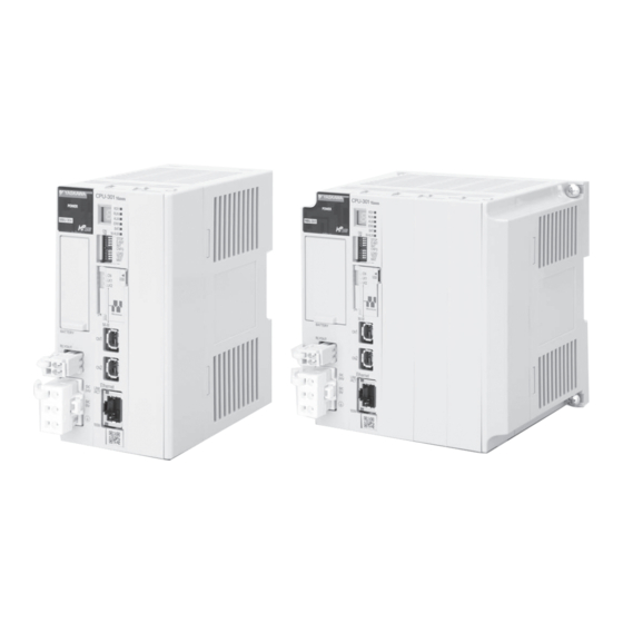
Related Manuals for YASKAWA MP3300iec


Summary of Contents for YASKAWA MP3300iec
- Page 1 YASKAWA MP3300iec Machine Controller Hardware Manual Type: MP3300iec To properly use the product, read this manual thoroughly and retain for easy reference, inspection, and maintenance. Ensure the end user receives this manual. MANUAL NO: YAI-SIA-IEC-7...
-
Page 3: Table Of Contents
Yaskawa. No patent liability is assumed with respect to the use of the information contained herein. Moreover, because Yaskawa is constantly striving to improve its high-quality products, the information contained in this manual is subject to change without notice. - Page 4 YASKAWA America, Inc. MP3300iec Hardware Manual YAI-SIA-IEC-7...
-
Page 5: Basic Units
Optional Modules. Base Unit Contains the power supply and provides the backplane to which Modules are mounted. The Basic Modules are typically connected as shown in the following examples. CPU Module Base Unit YASKAWA America, Inc. MP3300iec Hardware Manual YAI-SIA-IEC-7... -
Page 6: System Configuration Example
Front cover for unused slot 24-VDC power supply or AC power supply MECHATROLINK-III Cable MECHATROLINK-III SERVOPACK with MECHATROLINK-III Communications I/O Module with MECHATROLINK- Communications Servomotor Servomotor Servomotor Up to 62 stations, including I/O YASKAWA America, Inc. MP3300iec Hardware Manual YAI-SIA-IEC-7... -
Page 7: Component Part Numbers
CPU, MP3300, 20 axis, 800 MHz, 8MB SRAM PMC-U-MP33332 CPU, MP3300, 32 axis, 800 MHz, 8MB SRAM JEPMC-BU3304-E Base Unit with DC Power Supply, 1 Slot, MP3300iec JEPMC-BU3303-E Base Unit with DC Power Supply, 3 Slots, MP3300iec Base Unit JEPMC-BU3302-E... -
Page 8: Base Units
Base Unit and describes the connector. Appearance and Part Names Figure 1 illustrates the appearance of the Base Unit and a part name. Figure 1 RLYOUT connector Power connector Figure 1 Base Unit YASKAWA America, Inc. MP3300iec Hardware Manual YAI-SIA-IEC-7... - Page 9 4-2013522-3 White Pin Assignments Signal Label Description 24 VDC Power input wire for 24 VDC 0 VDC Power input wire for 0 VDC Connects to the frame ground. (Ground to 100 W max.) YASKAWA America, Inc. MP3300iec Hardware Manual YAI-SIA-IEC-7...
-
Page 10: Cpu Specifications
PC Use the YDeviceComm firmware library to create a custom Custom Protocol communication protocol. Variables configured with MotionWorks IEC software that allow Network Variables read/write automatic data transfer from controller to controller. YASKAWA America, Inc. MP3300iec Hardware Manual YAI-SIA-IEC-7... - Page 11 MECHATROLINK-III communications devices. Figure 5 Figure 5 MECHATROLINK-III Connectors Ethernet Connectors Figure 6 illustrates the connector used to connect Ethernet communications devices. Figure 6 Figure 6 Ethernet Connector YASKAWA America, Inc. MP3300iec Hardware Manual YAI-SIA-IEC-7...
- Page 12 NOTICE: Equipment Hazard. Before removing the USB memory device, press the STOP/SAVE switch and wait until the USB status indicator goes out. If the USB memory device is removed while the USB status indicator is lit or flashing, the data may become corrupted. YASKAWA America, Inc. MP3300iec Hardware Manual YAI-SIA-IEC-7...
-
Page 13: Installation And Usage Conditions
6 Installation and Usage Conditions Installation and Usage Conditions This section describes installation and usage conditions for the MP3300iec Series Machine Controllers. Install the MP3300iec Series Controllers in an environment with the following conditions. Installation and Usage Conditions Table 1 MP3300iec Installation and Usage Conditions... - Page 14 40 mm min. 40 mm Direction of air flow * For a control panel with natural cooling with the MBU-303 Base Unit: 30 mm min. Figure 8 Fan installation location and air flow direction YASKAWA America, Inc. MP3300iec Hardware Manual YAI-SIA-IEC-7...
-
Page 15: Base Unit Specifications
• 125 Vac, 0.4 A resistive load, 0.20 A inductive load • 24 Vdc, 0.5 A resistive load, 0.25 A inductive load Indicators POWER POWER: Power supply connector Connectors RLY OUT: Relay contact connector YASKAWA America, Inc. MP3300iec Hardware Manual YAI-SIA-IEC-7... -
Page 16: Switches
USB thumb drive is available in any other circumstances. Table 6 Operation of LOAD and MNT for USB Thumb Drive E-INIT -- / DHCP Load user project from USB thumb drive Install firmware and user project from USB thumb drive YASKAWA America, Inc. MP3300iec Hardware Manual YAI-SIA-IEC-7... -
Page 17: Display And Indicators
ON at initial power up while firmware is loading. Turns off if firmware is valid. ON when a critical error occurs requiring a power cycle to recover. ON when the battery needs replacing. M-ALM ON when JL100 (Mechatrolink Master) chip initialization fails. YASKAWA America, Inc. MP3300iec Hardware Manual YAI-SIA-IEC-7... - Page 18 Status When Not Lit, Lit, or Flashing Lit: Ethernet link established. LINK/ACT Yellow Flashing: Ethernet communications activity. Not lit: 10 M connection 100M Green Lit: 100 M connection. We do not support GB connections. YASKAWA America, Inc. MP3300iec Hardware Manual YAI-SIA-IEC-7...
-
Page 19: Self-Configuration
The MotionWorks IEC (Express or Pro) configuration can detect the configuration and provide the user with configuration choices. If a StartUp Configuration was already saved on the controller, the self-configure function will not allow new devices to be discovered. In this case, add them offline manually first. YASKAWA America, Inc. MP3300iec Hardware Manual YAI-SIA-IEC-7... -
Page 20: Mechatrolink-Iii Specifications
Contacts normally open for RUN status (RDY indicator lit), and OFF for WDT error status. The relay Relay Output is built into the Power Supply Unit. Backup Circuit Battery: BR-1/2AA (Panasonic), 3.0 V YASKAWA America, Inc. MP3300iec Hardware Manual YAI-SIA-IEC-7... -
Page 21: Mechatrolink-Iii Network Topologies
12 MECHATROLINK-III Network Topologies MECHATROLINK-III Network Topologies You can connect the MP3300iec Series Controller and drives or I/O with cascaded connections, star connections, or mixed cascaded/star network topologies. The following figures show examples of these types of network topologies. ... - Page 22 You can also connect one additional Hub Module to the first Hub Module. CPU Unit Hub Module Hub Module Note: 1. Terminating resistors are not required. 2. The maximum number of stations that you can connect with star connections depends on the communications cycle. YASKAWA America, Inc. MP3300iec Hardware Manual YAI-SIA-IEC-7...
- Page 23 Note: 1. Do not connect more than 32 stations to a single CPU Unit port, including the Hub Modules. 2. The maximum number of stations that you can connect with a mixed cascaded/star connections depends on the communications cycle. YASKAWA America, Inc. MP3300iec Hardware Manual YAI-SIA-IEC-7...
-
Page 24: Mechatrolink-Iii Synchronization Between Modules
If asynchronous operation is set as a result of changing the communications cycle, an alarm will occur for the Servo axis and an I/O error will occur for the I/O station. If this happens, change the setting back to synchronized, save the settings to flash memory, and then cycle the power supply. YASKAWA America, Inc. MP3300iec Hardware Manual YAI-SIA-IEC-7... -
Page 25: Devices Connectable Via Mechatrolink-Iii
A20A I/O Modules The following table shows the module that is compatible with MECHATROLINK-III and can be connected to the controller. Model Details 64-point I/O Module JEPMC-MTD2310-E 24VDC, 64 inputs, 64 outputs YASKAWA America, Inc. MP3300iec Hardware Manual YAI-SIA-IEC-7... -
Page 26: Connecting The Rly Out Connector
Refer to the following figure for an example of connecting the RLY OUT connector. RLY OUT Power RLY OUT output supply Normal operation: ON Error: OFF 24-VDC 24 VDC power supply 0 VDC POWER Ground to 100 Ω max. YASKAWA America, Inc. MP3300iec Hardware Manual YAI-SIA-IEC-7... -
Page 27: Ethernet Connector Details
Lit: Connected at 100Mbps, or automatically negotiating 100M Green Unlit: Connected at 10Mbps Ethernet Cable For the Ethernet cable, use a twisted pair cable with RJ-45 connector. Yaskawa strongly recommends the use of shielded ethernet cables. Ethernet Category Remarks Type... - Page 28 100 m or less Number of HUBs between Nodes Up to four Unlimited Connection Example 2 MP3300iec 10 Base-T (crossover cable, up to 100m) The following are examples of Ethernet network connections via 100Base-Tx cable: YASKAWA America, Inc. MP3300iec Hardware Manual YAI-SIA-IEC-7...
- Page 29 • If necessary, increase the number of communication retries. • Yaskawa strongly recommends shielded Ethernet cables. 3. Attach a ferrite core. Ethernet: Attach it to the communication port side and the external equipment side of the MP3300iec unit. MP3300iec SERVOPACK...
-
Page 30: Option Module - Ai-01 (Analog Input) Module
±0.1% (±10 mV) ±0.1% (±0.02 mA) Accuracy 0 to 55°C ±0.3% (±30 mV) ±0.3% (±0.06 mA) Input Conversion Time 1.4 msec Max CN1: Input connector Connectors CN2: Input connector LED Indicator RUN (green) YASKAWA America, Inc. MP3300iec Hardware Manual YAI-SIA-IEC-7... - Page 31 Applicable Cable: JEPMC-W6080-oo Standard Cable Model and External Appearance Model Length External Appearance (JEPMC-W6080-oo) JEPMC-W6080-05 0.5 m NP JEPMC-W6080-05 Marking tube (Label) 26-core JEPMC-W6080-10 1.0 m Loose wires 150 mm JEPMC-W6080-30 3.0 m YASKAWA America, Inc. MP3300iec Hardware Manual YAI-SIA-IEC-7...
- Page 32 Mode switching terminal 1/5 Yellow Black – DN1/DN5 MDN1/MDN5 Mode switching terminal 1/5 Pink – – V2/V6 V2/V6 Voltage input 2/6 Pink Black – – G2V/G6V G2/G6 Ground 2/6 Yellow Black – – G2A/G6A YASKAWA America, Inc. MP3300iec Hardware Manual YAI-SIA-IEC-7...
- Page 33 Orange Black – – DN4/DN8 MDN4/MDN8 Mode switching terminal 4/8 DANGER Columns “Label on Marking Tube”, “Signal Name”, and “Function” display the values for connectors CN1 and CN2 in the format “CN1/CN2”, respectively. YASKAWA America, Inc. MP3300iec Hardware Manual YAI-SIA-IEC-7...
- Page 34 17 Option Module - AI-01 (Analog Input) Module Circuit Configuration Multiplexer Voltage input Current input Mode 256.5 Ground Voltage input Current input Mode 256.5 Photocoupler Ground Converter Voltage input Current input Mode +15V 256.5 DC/DC -15V Converter Ground Shell YASKAWA America, Inc. MP3300iec Hardware Manual YAI-SIA-IEC-7...
- Page 35 AI-01 module to external devices because the wiring distance varies between the AI-01 module and each external device. • Ground the cable shield between an external device and the relay terminal block on the external device side. YASKAWA America, Inc. MP3300iec Hardware Manual YAI-SIA-IEC-7...
-
Page 36: Option Module - Ao-01 (Analog Output) Module
Current Consumption 500 mA Max Dimensions 125 × 95 (H×D) Mass 90 g Indicators Indicator Indicator Status when Lit Status when not Lit Color Green Normal operation Operation stopped (no access from CPU) YASKAWA America, Inc. MP3300iec Hardware Manual YAI-SIA-IEC-7... - Page 37 Color Orange Analog Output 0 Gray Analog Output 1 Orange Black Ground 0 Gray Black A_Pulse+ White Pulse input ground Yellow White Black Yellow Black C-Phase latch input common (5V) 10~20 Twisted-pair cable YASKAWA America, Inc. MP3300iec Hardware Manual YAI-SIA-IEC-7...
- Page 38 • Ground the cable shield between the external devices and the junction terminal block by the external device side. YASKAWA America, Inc. MP3300iec Hardware Manual YAI-SIA-IEC-7...
-
Page 39: Option Module - Do-01 (Digital Output) Module
To ensure the circuit protection, provide a protective element such as fuse in each output as shown in the above diagram. DO-01 Module Connections Connects the DO-01 Module to external output signals. YASKAWA America, Inc. MP3300iec Hardware Manual YAI-SIA-IEC-7... - Page 40 DO_11 DO_12 DO_13 DO_14 DO_15 OV_2 OV_2 +24V_3 OV_3 DO_16 DO_17 DO_18 DO_19 DO_20 DO_21 DO_22 DO_23 OV_3 OV_3 +24V_4 OV_4 DO_24 DO_25 DO_26 DO_27 DO_28 DO_29 DO_30 DO_31 OV_4 OV_4 N.C. N.C. YASKAWA America, Inc. MP3300iec Hardware Manual YAI-SIA-IEC-7...
- Page 41 — — — — Continuous 0V_4/8 Common ground 4/8 Pink — — — — Continuous Orange — 0V_1/5 Common ground 1/5 Gray — DO_01/33 Digital output 1/33 White — DO_03/35 Digital output 3/35 YASKAWA America, Inc. MP3300iec Hardware Manual YAI-SIA-IEC-7...
- Page 42 White ———————— DO_31/63 Digital output 31/63 Yellow ———————— 0V_4/8 Common ground 4/8 Pink ———————— DANGER Columns “Signal Name” and “Function” display the values for connectors CN1 and CN2 in the format “CN1/CN2” respectively. YASKAWA America, Inc. MP3300iec Hardware Manual YAI-SIA-IEC-7...
-
Page 43: Option Module - Lio-01/02 Module
LED Indicators and Switch Settings The LIO-02 Module status display LED indicators (LD1 to LD8) change based on the SW1 rotary switch settings. The following table shows the ON/OFF indicator display for digital input and digital output. YASKAWA America, Inc. MP3300iec Hardware Manual YAI-SIA-IEC-7... - Page 44 Encoder Input Phase-Z: 5V/12V photocoupler input, Max frequency: 500 kHz Latch input Position registration latch on phase-C or DI_01. Switches Rotary switch (SW1) Dimensions (mm) 125 x 95 (H x D) Mass 80 g YASKAWA America, Inc. MP3300iec Hardware Manual YAI-SIA-IEC-7...
- Page 45 Transistor, open collector source mode outputs Isolation Method Photocoupler Output Voltage +24VDC, ±20mv Output Current 100 mA Max Leakage Current When OFF 0.1 mA Max ON: 1 ms Max ON Time/OFF Time OFF: 1 ms Max YASKAWA America, Inc. MP3300iec Hardware Manual YAI-SIA-IEC-7...
- Page 46 Phase-Z: 5V/12V photocoupler input, Max frequency: 500 kHz Input Mode Phase-A/B, signed, incremental/decremental Position registration latch on phase-Z or DI_01. Latch Input Response time: 5 ms Max for phase-Z input; 60 ms Max for DI_01 input. YASKAWA America, Inc. MP3300iec Hardware Manual YAI-SIA-IEC-7...
- Page 47 Input common 0 Shield Frame ground Orange Black — Phase-A pulse (–) Gray Black — Phase-B pulse (–) Phase-C pulse White Black — PCL5 (-5V input) Phase-C pulse Yellow Black — PCL12 (-12V input) YASKAWA America, Inc. MP3300iec Hardware Manual YAI-SIA-IEC-7...
- Page 48 Module Cable Manufacturer FCN-360C048-E (cover), Fujitsu I/O Connector FCN-365P048-AU FCN-361J048-AU (jack) component Cables Name Model Number Length (JEPMC-W2061-oo) JEPMC-W2061-A5 0.5 m Cable for LIO- JEPMC-W2061-01 1.0 m 01/02 Modules JEPMC-W2061-03 3.0 m YASKAWA America, Inc. MP3300iec Hardware Manual YAI-SIA-IEC-7...
- Page 49 • The pins A5 and B5, and the pins A6 and B6 are internally connected. Connect them externally as well. YASKAWA America, Inc. MP3300iec Hardware Manual YAI-SIA-IEC-7...
- Page 50 Digital output DO_24V 24 VDC Fuse Fuse DO_00 DO_01 DO_02 DO_03 DO_04 DO_05 DO_06 External output DO_07 signals DO_08 DO_09 DO_10 DO_11 DO_12 DO_13 DO_14 DO_15 DO_COM DO_COM Load External Fuse YASKAWA America, Inc. MP3300iec Hardware Manual YAI-SIA-IEC-7...
-
Page 51: Option Module - Lio-04/05 Modules
Lit: One of the output protection fuses is blown. Not lit: All of the output protection fuses are normal. DANGER The burnout detection circuit will not function when there is no external 24V power supply. YASKAWA America, Inc. MP3300iec Hardware Manual YAI-SIA-IEC-7... - Page 52 Refer to the following characteristics graph for details. 32 outputs Digital Outputs 24VDC transistor open-collector outputs, sink mode outputs RUN (green) Indicators ERR (red) Dimensions (mm) 125 x 95 (H x D) Mass 80 g YASKAWA America, Inc. MP3300iec Hardware Manual YAI-SIA-IEC-7...
- Page 53 LIO-04 Transistor, sink mode output Output Format LIO-05 Transistor, source mode output Isolation Method Photocoupler Output Voltage +24VDC (+19.2 to +28.8VDC) Output Current 100 mA Max Leakage Current When OFF 0.1 mA Max YASKAWA America, Inc. MP3300iec Hardware Manual YAI-SIA-IEC-7...
- Page 54 LIO-04 Digital Output Circuit (Sink Mode Output) Connection Example +24V Photocoupler +24V Output register DO_OUT Transistor LIO-05 Digital Output Circuit (Source Mode Output) Connection Example +24V +24V Output Transistor register DO_OUT Photocoupler YASKAWA America, Inc. MP3300iec Hardware Manual YAI-SIA-IEC-7...
- Page 55 DICOM_1/3 Digital Input common 1/3 Digital input 0/16 Gray — DI_00/16 (shared with interrupt input) White — DI_02/18 Digital input 2/18 Yellow — DI_04/20 Digital input 4/20 Pink — DI_06/22 Digital input 6/22 YASKAWA America, Inc. MP3300iec Hardware Manual YAI-SIA-IEC-7...
- Page 56 Digital output 13/19 Yellow ———————— DO_15/31 Digital output 15/31 Pink ———————— N.C. DANGER Columns “Signal Name”, “I/O”, and “Function” display the values for connectors CN1 and CN2 in the format “CN1/ CN2” respectively. YASKAWA America, Inc. MP3300iec Hardware Manual YAI-SIA-IEC-7...
- Page 57 Signal Name Function Orange — DICOM_1/3 Digital Input common 1/3 Gray — DI_00/16 Digital input 0/16 White — DI_02/18 Digital input 2/18 Yellow — DI_04/20 Digital input 4/20 Pink — DI_06/22 Digital input 6/22 YASKAWA America, Inc. MP3300iec Hardware Manual YAI-SIA-IEC-7...
- Page 58 Digital output 13/29 Yellow ———————— DO_15/31 Digital output 15/31 Pink ———————— N.C. DANGER Columns “Signal Name”, “I/O”, and “Function” display the values for connectors CN1 and CN2 in the format “CN1/ CN2” respectively. YASKAWA America, Inc. MP3300iec Hardware Manual YAI-SIA-IEC-7...
- Page 59 • Check the polarity of the external power supply when wiring. An adverse connection may cause a load malfunction. • The pins 39 and 43 and the pins 46 and 50 are internally connected. Connect them externally as well. YASKAWA America, Inc. MP3300iec Hardware Manual YAI-SIA-IEC-7...
- Page 60 • Check the polarity of the external power supply when wiring. An adverse connection may cause a load malfunction. • The pins 39 and 32 and the pins 46 and 50 are internally connected. Connect them externally as well. YASKAWA America, Inc. MP3300iec Hardware Manual YAI-SIA-IEC-7...
- Page 61 Output 12 Output 13 Load Output 14 External Fuse Output 15 (Installed by customer) DANGER Check the polarity of the external power supply when wiring. An adverse connection may cause a load malfunction. YASKAWA America, Inc. MP3300iec Hardware Manual YAI-SIA-IEC-7...
- Page 62 Load Output 28 External Fuse Output 29 (Installed by customer) Output 30 Output 31 DANGER Check the polarity of the external power supply when wiring. An adverse connection may cause a load malfunction. YASKAWA America, Inc. MP3300iec Hardware Manual YAI-SIA-IEC-7...
-
Page 63: Option Module - Lio-06 Module
Status when Lit Staus when OFF Green Normal Stopped. (No access by CPU) Fault Normal operation The ALM light indicates the following conditions • Fuse fault • ASIC error • A-phase disconnect • B-phase disconnect YASKAWA America, Inc. MP3300iec Hardware Manual YAI-SIA-IEC-7... - Page 64 ±5mA Output Delay Time 1.2ms (Time of change from -10+10V) DANGER The time constant shows the characteristics according to the input filter equivalent to the time to reach 0.632 × the input voltage. YASKAWA America, Inc. MP3300iec Hardware Manual YAI-SIA-IEC-7...
- Page 65 ON=0.5ms Max/OFF=0.5ms Max Number of Commons DI_01 is used together with the position registration latch input, and when enabled, the position Other Functions registration latch input latches with the pulse encoder when SI_01 is "ON". YASKAWA America, Inc. MP3300iec Hardware Manual YAI-SIA-IEC-7...
- Page 66 The fuses are not for circuit protection. They are for fire protection at output shorts. A fuse Protection Circuit should be attached outside each output when a protective circuit is necessary. Fuse Rating Error Detection Blown fuse detection YASKAWA America, Inc. MP3300iec Hardware Manual YAI-SIA-IEC-7...
- Page 67 The following shows an analog input response chart and input characteristics diagram for the LIO-06 module. Input Characteristics Response Chart Analog Input Value Input Register Value -10.5V -32768 -10.0V -31276 -5.0V -15638 0.0V +5.0V 15638 +10.0V 31276 +10.5V 32767 • Minimum linearity of +10.0V cannot be assured. YASKAWA America, Inc. MP3300iec Hardware Manual YAI-SIA-IEC-7...
- Page 68 Maximum Permissible Load Current ±5mA Resolution 16-Bit (-31276 to +31276) 25ºC ±0.1% (±10mV) Absolute 0 to 55ºC ±0.3% (±30mV) Output Delay Time 1.2ms (Time of change from -10+10V) Analog Output Circuit Connection Example YASKAWA America, Inc. MP3300iec Hardware Manual YAI-SIA-IEC-7...
- Page 69 C-Phase: 5V/12V/24V photocoupler input, max frequency 500kHz Input Mode A/B-phase, code, UP/DOWN counter, pulse, and direction Position registration latch with C-Phase of DI_01 Latch Input Response Time: Max 5s during C-Phase input, During DI_01 Input: Max 60s YASKAWA America, Inc. MP3300iec Hardware Manual YAI-SIA-IEC-7...
- Page 70 Standard Cable Wiring Table The following shows the standard cable wiring for the JEPMC-W2064 cable. Wire Color Markings Signal Name Function Orange — Analog Output Gray — Analog Input White — N.C. YASKAWA America, Inc. MP3300iec Hardware Manual YAI-SIA-IEC-7...
- Page 71 ———————— DO_01 Digital Output 1 Gray ———————— DO_03 Digital Output 3 White ———————— DO_05 Digital Output 5 Yellow ———————— DO_07 Digital Output 7 Pink ———————— DO_GND Digital output common ground Shell Shield Wire YASKAWA America, Inc. MP3300iec Hardware Manual YAI-SIA-IEC-7...
- Page 72 External Fuse External Fuse (Installed by customer) (Installed by customer) Connector Shell) DANGER The cable shield between the external equipment and the junction terminal block should be installed on the external device side. YASKAWA America, Inc. MP3300iec Hardware Manual YAI-SIA-IEC-7...
-
Page 73: Option Module - 218If-Y1
Sending and receiving RS-232 STRX Green Hardware control (LAN controller) data. Green Ethernet collision Hardware control (LAN controller) Green Transmitting Ethernet data. Hardware control (LAN controller) Green Receiving Ethernet data. Hardware control (LAN controller) YASKAWA America, Inc. MP3300iec Hardware Manual YAI-SIA-IEC-7... - Page 74 Engagement RJ-45 (cat.5) Plug connector Number Signal name Remarks Number Signal name I/O Remarks Transmission data + TXD+ side Pin layout Transmission TXD- RXD- Received data side data?Side RXD+ Receive data + side YASKAWA America, Inc. MP3300iec Hardware Manual YAI-SIA-IEC-7...
-
Page 75: Terminal Block Kit Cbk-U-Mp2A-Xx
Output 9 DI_01 input) DO_08 Output 8 DI_00 Input 0 DO_07 Output 7 DI_COM0 Input common 0 DO_06 Output 6 DI_COM1 Input common 1 DO_05 Output 5 Frame ground DO_04 Output 4 Frame ground YASKAWA America, Inc. MP3300iec Hardware Manual YAI-SIA-IEC-7... -
Page 76: Terminal Block Kit Cbk-U-Mp2B-Xx
Digital output 13 DO_29 Digital output 29 DO_05 Digital output 5 Digital output 7 (shared with position agreement DO_15 Digital output 15 DO_31 Digital output 31 DO_07 'COIN' signal) DO_GND Digital output 0V common YASKAWA America, Inc. MP3300iec Hardware Manual YAI-SIA-IEC-7... -
Page 77: Terminal Block Kit Cbk-U-Mp2C-Xx
24V power supply 3 +24V_5 24V power supply 5 +24V_7 24V power supply 7 +24V_1 24V power supply 1 +24V_3 24V power supply 3 +24V_5 24V power supply 5 +24V_7 24V power supply 7 YASKAWA America, Inc. MP3300iec Hardware Manual YAI-SIA-IEC-7... -
Page 78: Cable Shielding, Segregation And Noise Immunity
Wrong Shields tied Terminal Block back at device Connector Case WRONG Shield grounded at more than one point. Shields tied Terminal Block back at device Connector Case WRONG Shields of field cables ungrounded YASKAWA America, Inc. MP3300iec Hardware Manual YAI-SIA-IEC-7... - Page 79 27 Cable Shielding, Segregation and Noise Immunity Revision History The revision dates and the numbers of the revised manuals appear on the bottom of the back cover. Revision Date of Publication Section Revised Content Number May 2014 First Edition. YASKAWA America, Inc. MP3300iec Hardware Manual YAI-SIA-IEC-7...
- Page 80 27 Cable Shielding, Segregation and Noise Immunity YASKAWA America, Inc. MP3300iec Hardware Manual YAI-SIA-IEC-7...
- Page 82 Phone 81-4-2962-5151 Fax 81-4-2962-6138 YASKAWA AMERICA, INC. 2121 Norman Drive South, Waukegan, IL 60085, U.S.A. Phone (800) YASKAWA (800-927-5292) or 1-847-887-7000 Fax 1-847-887-7310 YASKAWA ELETRICO DO BRASIL LTDA. Avenida Fagundes Filho, 620 Sao Paulo-SP CEP 04304-000, Brazil Phone 55-11-3585-1100 Fax 55-11-5581-8795 YASKAWA EUROPE GmbH Hauptstraβe 185, Eschborn 65760, Germany...
Need help?
Do you have a question about the MP3300iec and is the answer not in the manual?
Questions and answers